Preprint
Article

This version is not peer-reviewed.

Dihedral Corner Region Camouflage in Radar Vision by Super-Dispersion Encoded Surfaces

A peer-reviewed article of this preprint also exists.

Submitted:

12 August 2025

Posted:

13 August 2025

You are already at the latest version

Abstract

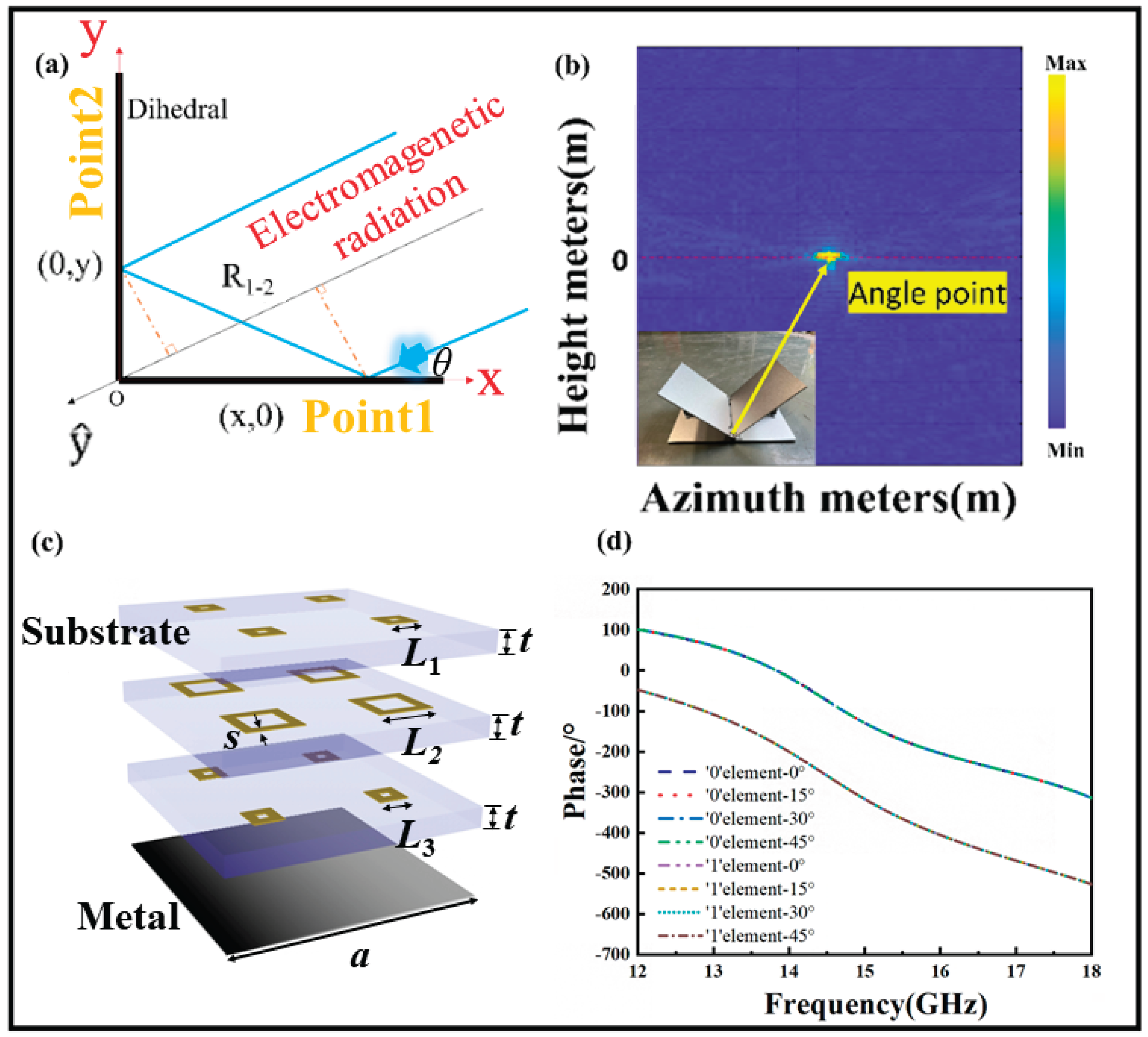
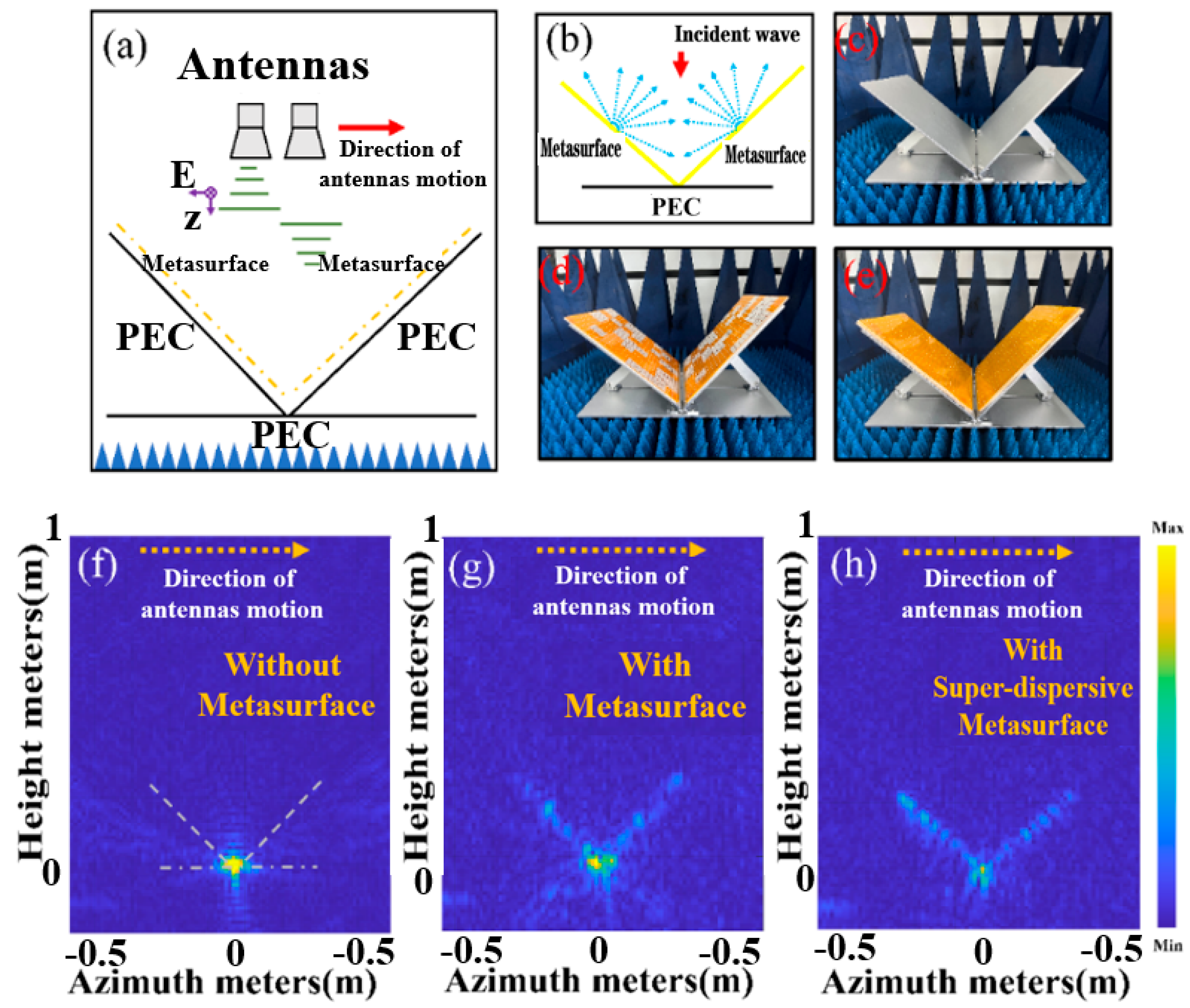
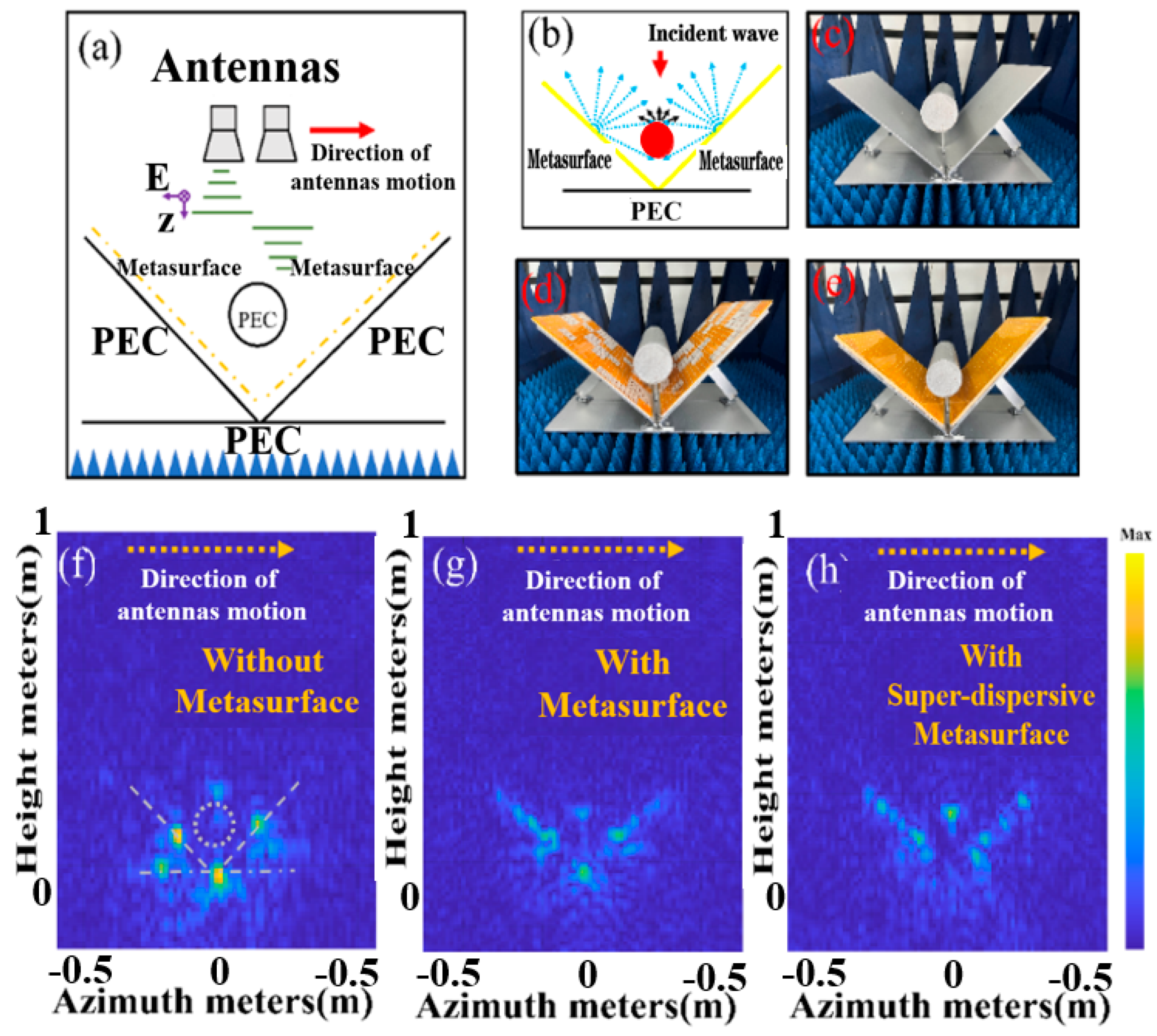
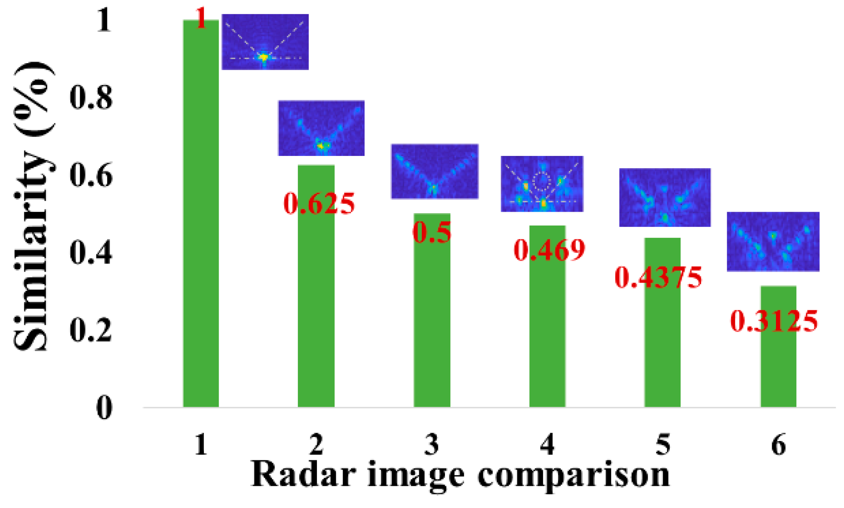
The dihedral angular structure is a key source of strong dispersion in radar images and serves as a crucial basis for radar image recognition. Modifying the scattering characteristics of the dihedral angular structure is essential for achieving stealth recognition in jamming radar systems. In this paper, we design a wideband super-dispersion coded surface (SDES) and apply it to the angular surfaces of dihedral angular structures to adjust their local scattering characteristics, enabling regional stealth camouflage. Experimental results show that the SDES effectively disperses the cumulative spectral components of dihedral angular structures, thereby modulating the radar target's scattering properties in these regions. Given that dihedral angular structures are often associated with cylindrical structures in practical applications, we also investigate the scattering characteristics of dihedral angular structures incorporating cylinders to further refine the stealth strategy. This research introduces a novel method for the stealth and camouflage of jamming target imaging radar and has the potential to be extended to other frequency bands, enabling multi-band electromagnetic wave stealth and camouflage.

Keywords: 
;  ;  

1. Introduction

With the rapid advancement of synthetic aperture radar (SAR) imaging and AI technologies, the accuracy of radar target detection and recognition has significantly improved [1,2], posing new challenges for the development of radar stealth and jamming strategies. Traditional stealth and camouflage coatings are constrained by the limitations of material systems and exhibit slow progress. Additionally, active radar jamming devices are costly, difficult to deploy, and unable to respond to electromagnetic waves instantly. As a result, there is an urgent need to develop novel camouflage strategies for radar imaging jamming. Dihedral angle structures are a major source of strong scattering in SAR radar imaging due to their unique multi-angle reflection properties, and the prominent scattering points they generate in radar images are key indicators for radar recognition. Thus, effectively changing the scattering characteristics of dihedral angle structure targets is a critical prerequisite for achieving stealth and camouflage in jamming radar systems. According to electromagnetic far-field theory, the far field represents the spatial Fourier transform of the radiation source. Consequently, the target’s scattering characteristics can be described as the spatial Fourier transform of the induced current and magnetic current generated by the target [3,4,5,6,7,8,9,10]. Altering the induced current on the target's surface can substantially affect its echo characteristics [15,16,17,18,19,20].
Diffuse scattering coding metasurfaces are a novel type of electromagnetic stealth material proposed in recent years. The coding units of these metasurfaces redirect the distribution of incident electromagnetic fields in space by changing the surface induced current, causing the incident electromagnetic waves to have a dispersed and chaotic response in space [21,22,23,24,25]. This disperses the Poynting vector of the electromagnetic waves, reducing echoes in specific directions and achieving stealth [26,27,28,29]. Based on their scattering effect on electromagnetic waves, coding metasurfaces can effectively change the propagation mode of electromagnetic waves and thus hold potential for changing scattering properties. To achieve this function, meticulous design of their spectral response to electromagnetic waves is required. Current research on diffuse scattering coding metasurfaces mainly focuses on the design and optimization of coding units [30,31,32], with little reported on their application in stealth and camouflage for specific structures, especially in the change of scattering properties.
In this paper, we propose a method for changing the scattering properties of dihedral corners by integrating a wideband super-dispersion encoded surface (SDES) onto the angular face of a dihedral angle to achieve the stealth in radar vision. We demonstrate that the SDES can mitigate the spectral accumulation of electromagnetic waves incident on the dihedral corner over a wide bandwidth, thereby significantly altering the radar target characteristics of the dihedral structure under grazing incidence. Theoretical analysis, simulations, and experiments confirm our conclusions.

2. Demonstration of Scattering Property Change Mechanism

Right-angle dihedral angle structures are among the most common radar target structures, and they elicit a strong response from single-base radars. Figure 1(a) illustrates the right-angle dihedral angle structure. Using the geometric optics method, we establish the y ^ axis as the straight line passing through the origin and parallel to the radar incident wave. This axis is equivalent to the xoy coordinate system rotated counterclockwise by θ + π / 2 degrees, where θ represents the angle of incidence. Assuming point 1's coordinates are (x, 0), the radar wave is relayed to point 2 (0, y), and then reflected back to the radar at the same angle θ , adhering to the principle of specular reflection.
To determine the distance traveled by the echo, we calculate the y ^ coordinates of points 1 and 2 in the radar irradiation coordinate system. Points sharing the same y ^ coordinate in the radar distance direction can be considered as one point. Specifically, for point 1, y ^ 1 = x cos θ , and for point 2, y ^ 2 = x tan θ sin θ . The distance traveled by the electromagnetic wave from point 1 to point 2 is defined as R 1 2 = x cos θ . Consequently, for a single-base radar, the phase difference generated from transmission to reception of the echo can be expressed as:
φ = 2 π λ y ^ 1 + y ^ 2 + R 1 2 = 2 π λ x c o s 2 θ cos θ x s i n 2 θ cos θ + x cos θ = 0
Equation (1) reveals that all distance-oriented information acquired by the radar becomes compressed to the corner point (0, 0) of the entire two-sided angular structure, resulting in a very strong echo signal at this point. Experimental results, as depicted in Figure 1(b), confirm the consistency between the measured 2D distance-azimuth direction imaging outcomes and the theoretically derived results.
Based on the aforementioned analysis, the critical factor in mitigating strong scattering at the corner point of a two-sided angle is the introduction of a phase difference between the transmitter and receiver to decompress the distance azimuthal direction. Consequently, the design's success hinges on achieving sufficient dispersion of the incident electromagnetic wave. The recent emergence of coded metasurfaces, capable of redirecting electromagnetic wave energy in space, lends theoretical support to the concepts proposed in this paper. By employing a coded metasurface on the corner surface of a two-sided angle, the electromagnetic wave can be effectively dispersed through its scattering effect, leading to the generation of a phase difference at various points on the corner surface. This approach holds promise for eliminating strong scattering points at the corner points. Consequently, the construction of a metasurface with the ability to efficiently disperse electromagnetic waves is of utmost importance.

3. Construction of SDES

It is the key to construct an electromagnetic metasurface with uniform dispersion of electromagnetic waves in the wide band range, which is called a wideband uniform scattering surface (SDES). Inspired by the dispersion-controlled metasurface, it is easy to use particle swarm optimization (PSO) algorithm to find two metasurface elements in the constructed database that are insensitive to incident in the broadband range. The SDES cell structure is shown in Figure 1(c), constructed using a 1-bit coding scheme (0 and 1 cells). Each unit consists of three dielectric layers and two layers of conductive patterned surfaces, with dimensions of a = 12.5 mm for the unit size, t = 2 mm for dielectric thickness, and s = 2 mm for the ring pattern width. Notably, only a limited number of frequency points within the 12-18GHz range are used to select the two elements. Since only two elements are required, this process is much simpler than the dispersion engineering used for achromatic focusing, and is thus referred to as simplified dispersion engineering. The dispersion curves for these two cells, in different incident directions, are presented in Figure 1(d). These curves demonstrate that the phase responses are nearly linear with similar slopes, ensuring a stable phase difference of approximately 180 degrees across a wide frequency range for various incident angles.

4. Experimental Validation for the Effect of the Scattering Property Changes by SDES

The experimental configuration is presented in Figure 2(a), where the single-site antenna undergoes horizontal sweeping at 4 mm intervals around the dihedral angle structure. This is performed at a vertical distance of 1 m. The frequency range of the setup spans from 12 GHz to 18 GHz. Specifically, the radar imaging employs the back projection (BP) algorithm, focusing exclusively on the polarization direction. To visually convey the concept of eliminating strong scattering points through SDES deployment, Figure 2(b) illustrates the arrangement of the SDES. The underlying idea hinges on capitalizing on the SDES's ability to sufficiently disperse electromagnetic waves, thereby introducing a non-zero phase difference in the optical path traversed by the emitted and received electromagnetic waves. This effect facilitates the dispersion of electromagnetic waves upwards over distance.
In fabricating the SDES samples, we utilized a Polyimide (PI) film with a thickness of 0.075 mm. This film was coated with ultra-low resistance silver paste through printing technology. Subsequently, the coated film was affixed to the customized dielectric foam, resulting in the creation of the SDES. This cost-effective approach yields samples with a shorter preparation timeline compared to conventional PCB circuit boards. For comparative purposes, we also prepared randomly coded metasurface using the same technique [33]. Subsequent experimentation encompassed radar distance azimuthal imaging of various configurations, including the dihedral corner metal structure, the dihedral corner structure with conventional metasurfaces, and the dihedral corner structure equipped with SDES. The corresponding experimental setups are depicted in Figure 2(c)–(e), while the resultant imaging outcomes are displayed in Figure 2(f)–(h). In the visualization, the horizontal coordinates correspond to the azimuthal direction, while the vertical coordinates denote the distance direction. The color scale portrays the magnitude of scattering intensity emanating from the scattering source. In Figure 2(f), in accordance with the theoretical derivation, the radar image of the dihedral corner structure exhibits distance-direction compression, positioning a scattering intensity point at the corner coordinates (0,0). Upon applying a conventional metasurface at the corner of the dihedral corner (depicted in Figure 2(g)), the distance direction begins to decompress and disperse due to the metasurface's scattering impact on electromagnetic waves. However, the dispersion on the corner surface lacks uniformity due to non-uniform scattering at various frequency points. Additionally, the coding pair formed by subarrays tends to concentrate in the angle of electromagnetic dispersion, preserving the existence of strong scattering points at the corner coordinates.
By introducing a SDES cell to the corner surface (depicted in Figure 2(h)), uniform dispersion of the distance direction is achieved across the dihedral angle's corner surface. This uniform dispersion arises from the broad frequency-dependent dispersion characteristics of the SDES cell. Notably, the strong scattering point at the corner location is notably attenuated, confirming the efficacy of our designed SDES in achieving substantial dispersion across a wide frequency range. This outcome underscores the feasibility of the concept illustrated in Figure 2(b). Nevertheless, the outcome in Figure 2(h) does not align with our initial expectation, as the strong scattering source at the corner point persists, albeit weakened.
To achieve complete elimination of the strong scattering point at the corner, we introduced a cylindrical structure to enhanced scattering. From the point of view of application, this introduction is necessary and acceptable. First of all, for many equipment, dihedral Angle structure is accompanied by metal cylindrical configuration of the structure, such as aircraft mounting area, vehicle hub, etc. Therefore, the combination of dihedral Angle structure and cylinder structure to study the effect of SDES structure on the overall scattering characteristics is of great significance.
The experimental configuration is illustrated in Figure 3(a). The crucial role of incorporating metal cylinders in attaining scattering point suppression and enabling distance-directed camouflage is underscored. Firstly, due to its small electrical dimensions, the cylindrical structure can obstruct a portion of directly and vertically incident electromagnetic waves at the corner point, averting pronounced echoes. Secondly, the inherent scattering impact of the cylindrical structure on electromagnetic waves can disperse a portion of the originally compressed waves toward the corner surface. With the SDES positioned on the corner surface, echoes emitted from the SDES can be directed towards the cylindrical surface, thereby engendering multiple scattering occurrences, as depicted in Figure 3(b). Crucially, given that electromagnetic waves do not deviate from their course, elimination of the strong scattering point at the corner alters the scattering property of the dihedral angular structure. This comprehensive transformation in radar target attributes is further facilitated by the cylindrical structure, serving as a pivotal point for distance-directed camouflage in the upward direction.
Similar to the experiments in Figure 2, we conducted radar azimuthal distance imaging on the dihedral angular structure enhanced with metal cylinders, the cylindrical dihedral angular structure with conventional metasurfaces, and the electromagnetic shadow structure. The test configuration illustrations are presented in Figure 3(c)–(e), while the resultant imaging outcomes are showcased in Figure 3(f),(g).
Upon introducing the cylinder to the metal dihedral corner (Figure 3(f)), the initial strong scattering point at the corner (Figure 2(f)) divides into three points: the corner point and the centers of the two corner surfaces. In contrast, the cylinder's scattering energy is relatively minor and comparable to the energy from points near the strong scattering point on the corner faces. Employing a randomly metasurfaces on the corner surfaces (Figure 3(g)) leads to a noticeable weakening of the strong scattering point intensities at the corner points and surfaces, accompanied by partial distance direction compression on the corner surfaces. However, the scattering points at the corner points persist. Notably, by employing SDESs capable of uniformly scattering electromagnetic waves on the corner surface (Figure 3(h)), we observe the complete vanishing of the strong scattering point at the corner. This results in uniform dispersion of the distance direction across the corner surface, with no pronounced scattering points. Meanwhile, scattering intensifies at the metal cylinder's location. The strong scattering points at the corners were effectively eliminated by introducing structures within the corners and dihedral corners. Notably, the corners themselves underwent no modifications throughout this process. This technique bears resemblance to the "invisible door" technique, wherein a region of metamaterials manages electromagnetic wave responses outside that specific region. Our study underscores the feasibility of the invisible door technique once more, offering an auspicious platform for future illusion device designs.
Concurrently, our proposed strategy proves highly effective in achieving effective camouflage. In the context of radar image recognition, the electromagnetic scattering from a target can be effectively approximated by the summation of echoes originating from a series of independent, pronounced scattering structures, referred to as scattering properties. These scattering properties are derived from the geometric attributes of the target and their distribution traits closely align with the radar image characteristics. Thus, the spatial arrangement of these scattering properties stands as a pivotal factor in the radar image-based identification of the target. Consequently, the alteration of scattering properties becomes an essential requisite for successful camouflage.
Finally, we employed the Perceptual Hashing (pHash) algorithm, which is well-suited for radar image processing, to detect the similarity between two images. Unlike traditional hashing algorithms, perceptual hashing focuses on capturing the visual features of an image rather than just comparing the file contents at the byte level. By comparing the hash values of two images, the Hamming distance (i.e., the number of differing bits between two hash values) can be used to measure their similarity. This similarity can be further converted into a score ranging from 0 (completely different) to 1 (identical). According to data provided by the Swedish company Barracuda, a similarity score less than 0.7 indicates a major difference.
We calculated the radar image similarity between the images in Figure 2 and Figure 3, with the results shown in Figure 4. The similarity between Figure 2(f) and Figure 2(g) is 0.625, between Figure 2(f) and Figure 2(h) is 0.5, between Figure 2(f) and Figure 2(f) is 0.46875, between Figure 2(f) and Figure 3(g) is 0.4375, and between Figure 2(f) and Figure 3(f) is 0.3125. The comparison results between Figure 2(f) and Figure 3(h) show a similarity far below 0.7, indicating that this strategy effectively change the scattering characteristics associated with dihedral angles in radar perception.

5. Conclusion

This study introduces a novel approach to the application of metasurfaces in dihedral scattering property changing. Initially, broadband metasurface cells are employed for implementing diffuse scattering steganography. These selected cells demonstrate a consistent phase difference of 180 degrees across a wide frequency spectrum. Furthermore, it alters the original structure's scattering property. The presence of cylindrical columns acts as a pivotal point for radar distance-directed camouflage while simultaneously enhancing electromagnetic wave scattering. This newly suggested electromagnetic stealth technology in radar vision offers notable advantages such as significant effectiveness, straightforward fabrication, and cost-effectiveness. It holds valuable guidance for the realization of multifunctional electromagnetic stealth and camouflage devices and can be extended to other frequency bands for constructing innovative devices.

References

  1. H. Wang, W. H. Wang, W. Zhang, and Y. Zhang, "Automatic Target Recognition of SAR Images Based on a Fused Deep Learning Model," IEEE Transactions on Geoscience and Remote Sensing, 2019, vol. 57, no. 3, pp. 1730-1741.
  2. X. Li, Y. X. Li, Y. Shi, and S. Liu, "SAR Target Recognition via Joint Sparse Representation and Deep Learning Features," IEEE Transactions on Aerospace and Electronic Systems, 2019, vol. 55, no. 4, pp. 1884-1898.
  3. J. M. Jin, D. J. J. M. Jin, D. J. Riley, and D. S. Weile, "A Study of Induced Currents and Magnetic Fields in Electromagnetic Scattering Problems," IEEE Transactions on Antennas and Propagation,,2020, vol. 45, no. 8.
  4. R. F. Harrington and J. R. Mautz, "Field Computation by Moment Methods Applied to Electromagnetic Scattering," IEEE Transactions on Antennas and Propagation, 1971, vol. 19, no. 5, pp. 623-628.
  5. P. H. Pathak, N. P. H. Pathak, N. Wang, and R. J. Burkholder, "Fast Computational Techniques for the Analysis of Scattering and Radiation From Large Complex Targets," IEEE Transactions on Antennas and Propagation, 1997, vol. 45, no. 3, pp. 409-420.
  6. L. Tsang, J. A. L. Tsang, J. A. Kong, and R. T. Shin, "Theory of Microwave Remote Sensing Applied to Electromagnetic Scattering From Random Rough Surfaces," IEEE Transactions on Antennas and Propagation, 1982, vol. 30, no. 5, pp. 775-785.
  7. Freeman, A.; Durden, S.L. A three-component scattering model for polarimetric SAR data. IEEE Trans. Geosci. Remote Sens. 1998, 36, 963–973. [Google Scholar] [CrossRef]
  8. F. Xu and Y.-Q. Jin, "Automatic Target Recognition of SAR Images Based on the Fractal Feature," IEEE Transactions on Geoscience and Remote Sensing, 2007, vol. 45, no. 6, pp. 1746-1755.
  9. M. Soumekh, "Synthetic Aperture Radar Signal Processing with MATLAB Algorithms," John Wiley & Sons, 1999, pp. 352-358.
  10. Cloude, S.; Pottier, E. An entropy based classification scheme for land applications of polarimetric SAR. IEEE Trans. Geosci. Remote. Sens. 1997, 35, 68–78. [Google Scholar] [CrossRef]
  11. Y. Li, X. Y. Li, X. Zhao, and H. Chen, "Manipulation of Scattering properties for Radar Cross Section Reduction Using Metasurfaces," IEEE Transactions on Antennas and Propagation, 2017, vol. 65, no. 6, pp. 3245-3253.
  12. M. Chen, W. M. Chen, W. Cao, and C. R. Simovski, "Scattering Manipulation and RCS Reduction Using 3-D Printing of Dielectric Objects," IEEE Transactions on Microwave Theory and Techniques, 2018, vol. 66, no. 2, pp. 839-846.
  13. Q. Zhang, H. Q. Zhang, H. Zhang, and Y. Shi, "Control of Electromagnetic Scattering and Cloaking Using Tunable Metamaterials," Progress In Electromagnetics Research,,2017, vol. 160, pp. 183-196.
  14. Alù, A.; Engheta, N. Achieving transparency with plasmonic and metamaterial coatings. Phys. Rev. E 2005, 72, 016623. [Google Scholar] [CrossRef] [PubMed]
  15. Y. Li, X. Y. Li, X. Zhao, and H. Chen, "Manipulation of Scattering properties for Radar Cross Section Reduction Using Metasurfaces," IEEE Transactions on Antennas and Propagation, 2017, vol. 65, no. 6, pp. 3245-3253.
  16. W. Ma, P. W. Ma, P. Wang, and L. Wang, "Broadband Absorbing Metamaterials to Control the Scattering of Electromagnetic Waves," Advanced Optical Materials, 2017, vol. 5, no. 17, pp. 1700761.
  17. F. Costa, S. F. Costa, S. Genovesi, and A. Monorchio, "A Frequency Selective Radome with Polarization Diversity for Radar Cross Section Reduction," IEEE Transactions on Antennas and Propagation, 2012, vol. 60, no. 6, pp. 2740-2747.
  18. X. Shang, C. X. Shang, C. Chan, and K. F. Man, "Absorptive Frequency Selective Surface for Broadband Radar Cross-Section Reduction," IEEE Antennas and Wireless Propagation Letters, 2012, vol. 11, pp. 1394. [Google Scholar]
  19. Wqrner, D.; Ganguly, S. An overview of fractal antenna engineering research. IEEE Antennas Propag. Mag. 2003, 45, 38–57. [Google Scholar] [CrossRef]
  20. N. Landy, S. N. Landy, S. Sajuyigbe, J. Mock, D. Smith, and W. Padilla, "Perfect Metamaterial Absorber," Physical Review Letters, 2008, vol. 100, no. 20, pp. 207402.
  21. Cui, T.J.; Qi, M.Q.; Wan, X.; Zhao, J.; Cheng, Q. Coding metamaterials, digital metamaterials and programmable metamaterials. Light. Sci. Appl. 2014, 3, e218–e218. [Google Scholar] [CrossRef]
  22. G. D. Giovampaola and N. Engheta, "Digital metamaterials," Nat. Mater., 2014, vol. 13, no. 12, pp. 1115–1121.
  23. Jing, H.B.; Ma, Q.; Bai, G.D.; Cui, T.J. Anomalously Perfect Reflections Based on 3-Bit Coding Metasurfaces. Adv. Opt. Mater. 2019, 7. [Google Scholar] [CrossRef]
  24. L. Zhang, C. L. Zhang, C. Huang, J. Yang, K. P. Esselle, S. Xu, and Y. J. Guo, "Broadband Metasurface for High-Efficiency Diffuse Scattering and Multibeam Reflections," IEEE Transactions on Antennas and Propagation, 2020, vol. 68, no. 4, pp. 2980-2987.
  25. Cui, T.-J.; Liu, S.; Li, L.-L. Information entropy of coding metasurface. Light. Sci. Appl. 2016, 5, e16172–e16172. [Google Scholar] [CrossRef] [PubMed]
  26. Y. Yang, C. Y. Yang, C. Huang, B. Zheng, and S. Xu, "Coding Metasurface for Controlling Diffuse Scattering in Electromagnetic Waves," IEEE Antennas and Wireless Propagation Letters, 2019, vol. 18, no. 7, pp. 1469-1473.
  27. H. Li, W. H. Li, W. Tang, and T. J. Cui, "Multifunctional Diffuse Scattering Metasurface With Optical Transparency," Advanced Optical Materials, 2019, vol. 7, no. 1, pp. 1800679.
  28. Q. Ma, Z. Q. Ma, Z. Wang, and J. Geng, "Metasurface-Based Diffuse Scattering for Suppressing Radar Cross Section," Applied Physics Letters, 2019, vol. 115, no. 10, pp. 103502.
  29. L. Zhang, Q. L. Zhang, Q. Wen, Y. Zhang, and W. Liu, "Design and Optimization of Coding Metasurfaces for Diffuse Scattering Applications," IEEE Transactions on Antennas and Propagation, 2019, vol. 67, no. 4, pp. 2766-2774.
  30. X. Liu, H. X. Liu, H. Li, T. J. Cui, and Y. Liu, "Optimized Coding Metasurface for Efficient Diffuse Scattering Control," IEEE Antennas and Wireless Propagation Letters, 2018, vol. 17, no. 11, pp. 1976-1980.
  31. Y. Li, R. Y. Li, R. Cui, and W. Xu, "Coding Unit Design for Metasurfaces: Optimizing Scattering Patterns via Genetic Algorithms," IEEE Access, 2019, vol. 7, pp. 180562-180570.
  32. Liu, S.; Cui, T.J.; Zhang, L.; Xu, Q.; Wang, Q.; Wan, X.; Gu, J.Q.; Tang, W.X.; Qi, M.Q.; Han, J.G.; et al. Convolution Operations on Coding Metasurface to Reach Flexible and Continuous Controls of Terahertz Beams. Adv. Sci. 2016, 3. [Google Scholar] [CrossRef] [PubMed]
  33. Sun, Y.; Cao, X.; Yuan, H.; Sun, W.; Yuan, X.; Ding, F.; Chen, M. Symbiotic Electromagnetic Shadow for Regional Invisibility and Camouflage. ACS Appl. Mater. Interfaces 2024, 16, 35716–35722. [Google Scholar] [CrossRef] [PubMed]
Figure 1. Analysis of strong scattering points of dihedral angle structures, SDES cells, and their phase response. (a) The schematic representation of electromagnetic wave propagation in dihedral angle based on geometrical optics method. (b) Radar images of dihedral angle structures derived from experiments. (c) Schematic structure of the SDES cell. (d) Phase curves of selected '0' and '1' cells.
Preprints 172229 g001
Figure 2. Radar imaging experiments of dihedral angular structures. (a)Experiment setup. (b) Demonstration of principle. (c)-(e) represent, in order, experimental samples with dihedral angle structure, dihedral angle structure imposed normal metasurface and dihedral angle structure-imposed SDES. (f)-(h) Radar images of samples (c)-(e) obtained by BP projection algorithm.
Preprints 172229 g002
Figure 3. Radar imaging experiments of dihedral angular structures with the symbiotic cylinder. (a) Experiment setup. (b) Demonstration of principle. (c)-(e) represent, in order, experimental samples of dihedral angle structure with symbiotic cylinder, dihedral angle structure with symbiotic cylinder imposed normal metasurface and symbiotic electromagnetic shadow structures. (f)-(h) Radar images of samples (c)-(e) obtained by BP projection algorithm.
Preprints 172229 g003
Figure 4. Radar image similarity comparison.
Preprints 172229 g004
Disclaimer/Publisher’s Note: The statements, opinions and data contained in all publications are solely those of the individual author(s) and contributor(s) and not of MDPI and/or the editor(s). MDPI and/or the editor(s) disclaim responsibility for any injury to people or property resulting from any ideas, methods, instructions or products referred to in the content.
Copyright: This open access article is published under a Creative Commons CC BY 4.0 license, which permit the free download, distribution, and reuse, provided that the author and preprint are cited in any reuse.
Prerpints.org logo

Preprints.org is a free preprint server supported by MDPI in Basel, Switzerland.

Subscribe

Disclaimer

Terms of Use

Privacy Policy

Privacy Settings

© 2025 MDPI (Basel, Switzerland) unless otherwise stated