
Submitted:
11 August 2025
Posted:
12 August 2025
You are already at the latest version
Abstract
Small unmanned aerial vehicles (UAVs) are widely used in civil and military fields, and their noise problem has always been the industry’s focus. Compared with the traditional propeller fan, the ducted fan has the advantages of higher aerodynamic efficiency, lower aerodynamic noise, and higher safety. It has become the key power component of small UAVs. However, the aerodynamic acoustic performance, noise reduction effect, and noise reduction mechanism of the segmented ducted fan for small UAVs are still unclear, which restricts the noise reduction design process of the ducted fan. To solve these problems, RANS (Reynolds-Averaged Navier-Stokes) method, SST k-ω (Shear Stress Transport k-ω) turbulence model and broadband noise source model were used to establish a computational fluid dynamics model, and the effects of fan speed (20,000-40,000 r/min) and duct spacing (0-20 mm) on its aeroacoustic characteristics were systematically studied. The results show that the segmented ducted fan’s acoustic power level maximum (APLmax) is significantly higher than that of the traditional integral structure, especially at high speed. At 40,000 r/min, the increase of duct spacing to 20 mm led to the sudden increase of APLmax to 194.5 dB, 61.3 dB higher than that of the integral type. Its essence was derived from the three-stage chain amplification mechanism of “strong tip leakage vortex induced by geometric clearance → broadband noise caused by vortex impacting the duct wall → resonant coupling of leakage vortex harmonic frequency and duct cavity standing wave.” Based on this, a collaborative noise reduction path is proposed: compress the spacing to ≤ 10 mm to suppress the intensity of leakage vortex, design the periodicity of failure vortex combined with the serrated blade tip/inner wall rubber strip, and block the acoustic cavity resonance with non-uniform wall stiffness or 8-10 kHz Helmholtz resonator, providing a solution for the low-noise design of UAV propulsion system.
Keywords:
small UAVs
; ducted fan
; aerodynamic noise
; noise reduction mechanism
; noise reduction design
1. Introduction
With the rapid development of UAV technology, the application of small UAVs in the fields of logistics distribution, environmental monitoring, post-disaster rescue, aerial photography, medium and low altitude surveillance, and target strike in the military field has been expanding with its flexible mobility, low cost, and other advantages [1]. However, the noise problem caused by UAV operation has not been well solved, which will not only interfere with human daily living environments but also affect the concealment of special tasks, greatly limiting the application process of UAVs in specific scenarios [2]. Compared with the traditional propeller fan, the ducted fan (including propeller and outer duct) has the advantages of high aerodynamic efficiency, low noise, and safety. It has become the key power component of small UAVs. The study of its aerodynamic acoustic performance is significant for noise reduction design [1].
In recent years, domestic scholars have made systematic progress in studying the aerodynamic and acoustic characteristics of the ducted fan system. Luo et al. [1] studied the influence of the wind field through the URANS (Unsteady Reynolds-Averaged Navier-Stokes) method and sliding grid technology. They found that wind can cause unsteady effects, leading to the fluctuation of thrust at blade passing frequency, and when the wind speed increases, the rotor thrust increases. In contrast, the duct thrust decreases, and the total thrust changes little. At the same time, they pointed out that increasing the speed or fan radius can help improve the wind performance. Luo et al. [3] further studied the ground effect, found that the ground led to the decrease of duct thrust, the increase of rotor thrust, and the reduction of total thrust, and identified the small-scale stall unit varying with height and the significant thrust fluctuation caused by it. Luo et al. [4] used the dynamic grid technology to expand to the dynamic motion state, revealing the enhancement or weakening mechanism of the ground and ceiling effect in the process of rising and falling, and observed the Karman vortex street and vortex ring structure, with significant thrust changes. Luo et al. [5] studied hovering in a restricted environment and confirmed that the influence range of the proximity effect is within four rotor radii. The ground and ceiling effects significantly change the thrust, while the wall effect mainly affects the lateral force and pitching moment. Regarding distributed propulsion, Li et al. [6] proposed an equivalent design method, indicating that various distributed ducted fan configurations can achieve similar thrust at the same power, while reducing volume and improving efficiency, revealing the key impact of rotational consistency on performance. Wang et al. [7] studied the ducted coaxial propeller through experiment and simulation. They found that the increase of tip clearance will lead to the separation of air flow and the enhancement of the tip vortex, reducing efficiency, and installing a vortex suppression ring can effectively improve the aerodynamic performance. Wei et al. [8] emphasized the key role of coupling parameters such as tip clearance and blade relative position on the performance of the ducted rotor system, providing a basis for optimal design. In acoustic research, Liu et al. [9] systematically revealed the generation mechanism of steady-state load, thickness noise, and wake interaction noise through URANS simulation and analysis of a reverse rotating ducted fan, combined with the Hanson and ducted acoustic models. Wu et al. [10] proposed the application of Helmholtz-type acoustic metamaterials to the noise control of ducted fans. Combined with CFD (Computational Fluid Mechanics) and the finite element method, it was verified that it can effectively attenuate the first four orders of tonal noise and has little impact on ventilation efficiency. Sun et al. [11] studied the noise reduction effect of the short inlet on the cooling fan. They found that it can inhibit the propagation of upstream tonal noise and weaken the rotor interaction by changing the inlet vortex structure. Wang et al. [12] experimentally studied the noise control method of inserting a turbulence grid between the propeller and the strut, and found that the complete shadow and tip shadow configurations can achieve about 3 dB noise reduction. Lu et al. [13] studied the noise characteristics of the compressor. They found that the noise near the stall point increased significantly, the intensity of the surface source increased, and an additional peak frequency appeared. The acoustic response showed significant differences in the duct. To sum up, these studies deepen the understanding of the aeroacoustic mechanism of ducted fans in complex environments and operating conditions from multiple dimensions, and provide necessary support for UAV flight control and advanced propulsion system optimization.
In foreign countries, systematic progress has also been made in fan aeroacoustics’ experimental, numerical simulation, and optimization design. Lendvai et al. [14] studied the blade tip-related noise of a ducted fan through experiments and CFD. They found that the dominant noise at high flow velocity was turbulent boundary layer trailing edge noise. In contrast, the leading-edge noise at low flow velocity was significant and closely related to tip leakage flow. The downstream array further identified the superposition of multiple trailing-edge noise sources. Hickey et al. [15] carried out a winglet Optimization Study on a small axial fan, tested 20 configurations, and found that the medium smooth winglet on the suction side had the best comprehensive effect in improving efficiency and reducing noise. Numerical simulation revealed that it reduced loss and noise by controlling tip clearance flow. Lewis et al. [16] used the large eddy simulation method to predict the broadband noise of the ACAT1 fan level, and found that the fine grid significantly improved the prediction accuracy of the flow field and noise. Combined with FW-H (Fwowcs Williams and Hawkings) and Goldstein acoustic analogy, they revealed other important broadband sources besides rotor-stator interaction noise, challenging the traditional single dominant mechanism hypothesis. Kusuda et al. [17] studied the influence of back pressure distortion caused by the downstream tower on the pitch noise of the fan in combination with experiments, CFD, and duct acoustic theory. They found that the tower rotor interaction caused unsteady load and shock wave fluctuations, excited high-mode pressure sound waves, and significantly reduced the critical instability speed. Hirono et al. [18] carried out aerodynamic and Aeroacoustic design for the electric ducted fan. CFD and experiments verified the influence of different design flow coefficients, and found that when the flow coefficients were 0.75 and 0.90, they had more advantages in performance and noise. Yokoyama et al. [19] explored plasma actuators’ use to control axial-flow fans’ flow and sound fields. They found that the reverse circumferential induced flow can effectively suppress the resonant sound of the duct at low and medium flow rates. Experiments verified the reduction of acoustic resonance while maintaining flow rates. Ghosh et al. [20] studied the aeroacoustic characteristics of parallel low-pressure axial-flow fans through DDEs (Delayed Detached Eddy Simulation) and identified the local diffusion zone and new vortex structure. Acoustic analysis showed that the two fans’ sound field interaction was limited, and the sound spectrum was close to 6 dB superposition. Dietrich et al. [21] used the fast random particle grid turbulence reconstruction method to simulate the acoustic response of the fan under turbulent inlet conditions, avoiding the high computational cost of directly simulating the complex upstream structure, and providing a feasible path for noise prediction under actual working conditions. Li et al. [22] developed a low-order prediction method for fan level broadband interactive noise assisted by machine learning. They used CFD data to train the model to extract wake characteristic parameters, which were used to quickly predict the response noise of the fan outlet guide vane, showing the potential for efficient modeling. Pouryoussefi et al. [23] experimentally studied the boundary layer intake (BLI) effect of the embedded wing ducted fan. It was confirmed through pressure measurement, smoke visualization, and hot wire anemometer analysis that BLI can improve aerodynamic performance, inhibit separation, and delay stall. Suzuki[24] studied the spiral flow instability between rotor and stator in high-speed turbomachinery, combined with linear stability analysis and IDDES(Improved Delayed Detached-Eddy Simulation). A variety of unstable modes and their correlation with broadband noise are identified. It is found that the coherent structure dominates the outer wall pressure fluctuation and is coupled with the acoustic mode. Blázquez-Navarro et al. [25] verified the broadband noise prediction method based on the linearized Navier-Stokes equation. Taking the ACAT1 fan as the object, comparing the RANS (Reynolds-Averaged Navier-Stokes) and experimental data, the results showed that the overall prediction of the noise spectrum was good, and the azimuth decomposition was consistent. At the same time, it was first quantified that increasing the axial clearance of the fan/OGV (Outlet-Guide-Van) might aggravate the noise, providing counterintuitive but essential conclusions for the design. To sum up, these studies deepen the understanding of fan aerodynamic noise’s generation and propagation mechanism from multiple perspectives, and promote the development of efficient and low-noise design methods.
To sum up, scholars at home and abroad have significantly contributed to fan aerodynamic noise analysis and noise control methods. However, the above research mainly focuses on the aeroacoustic performance of the integral ducted fan (the fan outer duct is the integral structure) and its blades. The aeroacoustic performance and noise reduction effect of the segmented ducted fan (including two outer ducts) are not apparent, which restricts the noise reduction design process of the ducted fan.
Aiming at the above problems, this paper seeks to clarify the segmented ducted fan’s aeroacoustic performance and noise generation mechanism, and put forward control methods. The innovation work is to reveal the aeroacoustic performance law and noise generation mechanism of the segmented ducted fan of a small UAV. The specific research idea is to design a segmented ducted fan based on the integral ducted fan, and establish a CFD finite element model to explore the influence of fan speed and ducted spacing on the aerodynamic acoustic characteristics of the ducted fan, to determine the noise source, influencing factors, and noise reduction effect. Finally, combined with the existing theory and simulation data, the influence mechanism of different working conditions on aerodynamic noise and its countermeasures is analyzed.
Therefore, the core content of this paper can be divided into four parts: (1) the basic theory of aeroacoustic characteristics of ducted fan, which provides theoretical support for the subsequent discussion of results and the analysis of noise generation mechanism; (2) numerical simulation method of aerodynamic noise of a ducted fan to establish a reliable CFD finite element model; (3) results and discussion: the simulation results reveal the generation mechanism of segmented ducted fan noise; (4) conclusions: summarize the key findings and outlook.
2. Basic Theory of Aeroacoustic Characteristics of the Ducted Fan
2.1. Working Principle and Governing Equation
The ducted fan mainly comprises blades, duct, and motor (as shown in Figure 1). The duct has the functions of guiding the air flow, improving the propulsion efficiency of the fan, reducing the eddy current loss at the blade tip, and reducing the noise generation. Its core advantages are compact structure and high thrust density, making it suitable for lightweight and low noise of small UAV [1]. Its working principle is that the blade rotation drives the surrounding air flow to generate thrust, and its duct is used as a guide device to guide the air flow direction to reduce the turbulence of air flow and energy loss [26]. The thrust F generated by the fan can be expressed as [23]:
where ṁ is the air mass flow, and VOutlet and VInlet are the air velocities at the outlet and inlet of the duct, respectively. According to formula 1, the duct design aims to make the VOutlet significantly larger than the VInlet to generate effective thrust.
The governing equations to be solved include the continuity equation (formula 2) and the momentum conservation equation (formula 3). To simplify the calculation, the fluid is regarded as an incompressible fluid, so the governing equation is [11,13,27]:
where ρ is the fluid density, μ is the dynamic viscosity, p is the fluid pressure, t is the time, u, v and w are the velocity components of the fluid in the x, y and z directions, Fx, Fy and Fz are the forces of the fluid in the x, y and z directions, div is the divergence operator, and grad is the gradient operator.
In addition, SST (shear stress transport model) is adopted as the turbulence model, which has the following advantages: (1) using the k-ω model in the boundary layer near the wall can give full play to the benefits of the k-ω model in small dissipation and good convergence of turbulence near the wall; (2) using the k-ω model in the far-field region has high computational efficiency and better adaptability to complex flow fields; (3) the model is universal. The transport equation can be expressed as [27]:
The turbulent kinetic energy equation is:
The dissipation rate equation is:
where Gk is turbulent kinetic energy, Γk and Γω are the effective diffusion terms of k and ω, respectively, ui is the velocity component, Yk and Yω are the divergent terms of k and ω, respectively, Dω is the orthogonal divergent term, Sk and Sω are custom source items.
Subsequently, formulas 2-5 will be solved based on the finite element method to obtain the pressure distribution and velocity distribution of the ducted fan flow field under different working conditions and reveal the noise generation mechanism of the segmented ducted fan.
2.2. Noise Generation Mechanism of the Integral Ducted Fan
The noise of a ducted fan mainly comes from aerodynamic noise, including the noise generated by the interaction between the blade and air (such as vortex noise caused by airflow turbulence), and the additional noise caused by the obstruction, interference, or acceleration of airflow caused by the ducted structure. When analyzing its acoustic characteristics, we should start with the generation mechanism of aerodynamic noise (such as turbulence, blade passing frequency, gap effect) and acoustic parameters (such as sound pressure level, acoustic power level). Among them, aerodynamic noise is mainly composed of broadband noise generated by turbulence around the blade and discrete noise caused by the interaction between the blade and the inner wall gap of the duct [9,10]. According to the classical aeroacoustic theory, the relationship between the total sound power W generated by the blade and the rotating speed N and the blade length R can be approximately expressed as [29,30,31]:
Mechanical noise is also one of the sources of ducted fan noise. It comes from the vibration of the motor, bearing, and other components. Although the energy proportion is small, it cannot be ignored under specific working conditions. It forms radiated sound through structural transmission, which is significant at low speeds or static. The noise frequency characteristic of a ducted fan is usually closely related to blade speed N, blade number B, and harmonic order i, and its blade passing frequency fN can be expressed as [13]:
2.3. Evaluation Parameters of Ducted Fan Noise Level
In acoustic simulation and analysis of a ducted fan, acoustic parameters are the basis for evaluating and controlling the noise level. The commonly used acoustic parameters include sound pressure and power levels, etc. The sound pressure level Lp reflects the strength of the sound wave when it propagates in space, which is defined as [12,15]:
where p is the sound pressure and p0 is the reference sound pressure, usually 2×10⁻⁵ Pa.
Acoustic power level (APL) LW is the total sound energy radiated by the sound source per unit time, which is the inherent characteristic of the sound source, and its calculation formula is [28]:
where S is the area of the measuring surface.
According to formula (9), the APL quantifies the sound energy the source radiates. Its value is not affected by the measurement location and environment, and can be directly related to aerodynamic parameters (such as speed and flow). Therefore, it is suitable for quantitative comparison of aerodynamic and acoustic characteristics of ducted fans under different working conditions (such as evaluation of noise reduction effect before and after optimization).
3. Numerical Simulation of Aerodynamic Noise of Ducted Fan
In this paper, based on the quasi-steady numerical simulation method of RANS, SST k-ω turbulence model is used to capture the turbulent characteristics in complex flow effectively, and the broadband noise source model is used to solve the vortex noise of ducted fan (refer to subsection 2.2). In addition, using the multiple reference coordinate system method, the rotating domain surrounds the rotating part, and the stationary domain surrounds the stationary part. The connection between the two is realized through two non-overlapping surfaces: the interface. The flow field in the stationary domain is solved in the inertial coordinate system. In contrast, the flow field in the rotating domain is solved in the rotating coordinate system, and the rotating coordinate system’s rotating speed is set to simulate the fan speed.
3.1. Segmented Ducted Fan and Boundary Condition Setting
Taking the ducted fan (integral type) of the small UAV commonly used in the market as the reference object (Figure 1a), its key parameters are shown in Table 1. According to the key parameters and considering the main geometric factor of the follow-up study, which is the ducted spacing, after retaining the key structure, the physical object is geometrically simplified, and the geometric model of the integral ducted fan is established, as shown in Figure 1b. On this basis, under the condition that the length of the duct remains unchanged, the duct is divided into two parts (the total length of the duct is 58 mm, and the length of the duct in its rotating area is 24 mm). The geometric model of the segmented ducted fan is established by adjusting the duct spacing, as shown in Figure 2a. The geometric model and boundary conditions of the calculation domain are shown in Figure 2b. The calculation domain should be long enough to capture the information of the wake field passing through the ducted fan, set to 22D (D is the outer diameter of the ducted fan, 73 mm), and its diameter is set to 7D, to avoid mutual interference of the boundary layer during the simulation process. In addition, the inlet and outlet of the calculation domain are a pressure inlet and a pressure outlet, respectively. The fan blade (mark the propeller in the rotating domain as a rotating part and specify its rotation direction to distinguish the relative motion relationship between the stationary domain and the rotating part), the duct, the motor, and the boundary outside the calculation domain are set as wall boundary conditions.
3.2. Grid Generation Strategy and Simulation Settings of the Computing Domain
Fluent meshing is used for high-quality polyhedral meshing and boundary layer meshing. Different mesh densities for different regions must be set to ensure the high accuracy of the result. The key size parameters and quality indicators of the computational domain grid are shown in Table 2. For the rotating domain where the ducted fan blade is located, the grid size is controlled to be 0.5-0.7 mm to accurately capture the characteristics of the blade boundary layer and vortex. Considering the calculation efficiency, for the area where the duct and motor are located, the grid size is set as 1-1.2 mm, and for other places, the grid size is set as 1.5 mm. In addition, orthogonality, distortion, and stretching ratio are used to evaluate the quality of grid elements. It can be seen from Table 2 that the orthogonality of the grid element is greater than 0.7, the twist degree is less than 0.3, and the tensile ratio is controlled within 5 to ensure numerical stability. The schematic diagram of the divided computational domain grid is shown in Figure 3. For the grid around the blades, ducts, and motors, the multi-layer boundary layer grid (15 layers) is set. The dimensionless dimension y+ < 1 of the grid height of the first layer of the boundary layer is set to meet the requirements of the turbulence model for boundary layer analysis, to ensure the acquisition of high-precision acoustic features. The grid division strategy of the computational domain above lays the foundation for the reliability calculation of the aerodynamic and acoustic characteristics of the ducted fan.
Table 3 shows the numerical simulation parameters. According to the selected no-load speed of the motor up to 40,000 r/min, set the fan speed to 20,000-40,000 r/min. In the follow-up, the influence of fan speed on the aerodynamic noise of the ducted fan is mainly considered, and the influence of incoming flow is not considered, so the inlet pressure is set to 0. In addition, it can be seen from Section 2.1 that to simplify the calculation, the fluid is regarded as an incompressible fluid, so the parameters of air are set to constant (density is 1.225 kg/m3, dynamic viscosity is 1.7894 × 10⁻⁵ pas).
3.3. Reliability Verification of the CFD Finite Element Model
In the acoustic simulation of a ducted fan of a small UAV, the verification of grid independence is the key link to ensure the reliability of the calculation results. The grid density around the duct fan, the inner and outer walls of the duct, and the motor is controlled uniformly (grid size regulation). Under a rotating speed of 20,000 r/min, the influence of the integral and segmented grid density on APLmax (APL maximum) is obtained, as shown in Table 4. It can be seen from Table 4 that the APLmax of the integral and segmented ducted fans (ducted spacing is 10 mm and 20 mm, respectively) decreases slightly with the decrease of grid density. The results show that the mesh density is reduced by about 30%, and the APLmax of the integral ducted fan is only reduced by about 1.5%. For segmented ducted fans with a spacing of 10 mm, the grid density decreases by about 13.4%, and APLmax only decreases by about 1.1%. The grid density is reduced by about 20%, and the APLmax of ducted fans with 20 mm spacing is only reduced by about 0.8%. To sum up, the grid scheme adopted in this paper has little effect on APLmax, which is no more than 1.5%, which preliminarily verifies the reliability of the CFD finite element model and can realize the reliability calculation of the aerodynamic and acoustic characteristics of the subsequent ducted fan.
4. Results and Discussion
4.1. Influence of Fan Speed on the Aeroacoustic Performance of an Integral Ducted Fan
This part takes the integral ducted fan as the research object. It aims to further verify the reliability of the numerical simulation method in this paper, combined with the content of the second part, to ensure the subsequent reliable analysis of the aerodynamic noise law of the segmented ducted fan. It can be seen from Figure 4a that the increase of ducted fan speed has a significant positive impact on the noise level (APLmax), showing a clear monotonic increasing trend. Specifically, when the fan speed increases linearly from 20,000 r/min to 40,000 r/min, the APLmax value rises from 116.5 dB to 133.2 dB. In this process, the increase of APLmax is non-linear and uniform, but shows an acceleration effect (following formula 6). Specifically, APLmax was 116.5 dB at 20,000 r/min, and increased to 118.4 dB (+1.9 dB) at 25,000 r/min. However, APLmax jumped from 128.6 dB to 133.2 dB (+4.6 dB) at 35,000 r/min to 40,000 r/min, indicating that the contribution of the increase in per unit speed to the improvement of noise was significantly increased at higher speeds. Overall, APLmax increased by 14.3% (relative to APLmax at 20,000 r/min), which reflects the inherent laws of machinery and fluid dynamics during fan operation, that is, the increase of rotating speed leads to the rise of blade rotating frequency and tip speed (following formula 7), which directly aggravates the disturbance of air, and thus enlarges the noise energy exponentially (following formula 6). This trend highlights that in the design of high-speed fans, speed control, as a key variable of noise management, must weigh the performance requirements and the impact of the acoustic environment. The specific noise generation mechanism is as follows.
The increase in the speed of the ducted fan not only increases the noise but also synchronously enhances the maximum pressure (Pmax) and the maximum velocity (Vmax) of the flow field, which together drive the noise generation mechanism. As shown in Figure 4a, Pmax rises from 1,124 Pa at 20,000 r/min to 4,666 Pa at 40,000 r/min; Figure 5a shows that Vmax rises from 89.1 m/s at 20,000 r/min to 152.4 m/s at 40,000 r/min. Pmax and Vmax showed an upward trend similar to APLmax with speed, indicating that the increase in speed exacerbated the dynamic pressure and velocity of the flow field. According to the comparison of velocity nephogram in Figure 5b under the conditions of 20,000 r/min and 40,000 r/min, the main reason for the noise mechanism is that at 20,000 r/min, the velocity nephogram (blue background) shows that the velocity distribution is uniform and the gradient is gentle (the velocity around the white fan structure is stable), at this time, the pressure fluctuation is slight (Figure 4c), and the noise is low (about 116.5 dB); At 40,000 r/min, the velocity nephogram shows that the high-speed area (color area) is significantly expanded and the intensity is higher (Figure 5b shows that the high-speed area is concentrated at the blade tip), while the corresponding effect of the pressure nephogram shows that the local high-pressure points increase (Figure 4c), which leads to flow separation, vortex shedding and a sharp increase in turbulence intensity, causing broadband turbulence noise and discrete noise (it can be seen from formula 7 that the blade passing frequency increases) [7]. The noise generation mechanism is essentially the amplification of pressure fluctuation induced by velocity gradient, that is, the collision frequency and energy of gas molecules increase in high-speed, and the pressure fluctuation propagates through sound waves. The cloud image visually shows the correlation between high velocity region and high noise region (as shown in Figure 4b and Figure 5b, the high-speed region of 40,000 r/min cloud image is larger, corresponding to 133.2 dB noise), indicating that the noise law conforms to the classical aerodynamic noise theory (following formula 6) [24]. Therefore, the core mechanism of ducted fan noise is the enhancement of hydrodynamic instability. The increase in rotating speed directly intensifies the intensity of the noise source by amplifying the flow speed and pressure gradient.
In conclusion, the above research results verify the reliability of the aeroacoustic numerical simulation method in this paper. They can be used to qualitatively analyze the aerodynamic noise characteristics and noise generation mechanism of the segmented ducted fan.
4.2. Effect of Spacing on the Aeroacoustic Performance of a Segmented Ducted Fan
Table 5 shows the influence of duct spacing on the acoustic performance of duct fans (the integral duct fan is taken as the reference object, and its duct spacing is 0 mm). The results show that the sensitivity of duct fan noise to spacing is highly dependent on the rotation speed, and the influence is weak (+5.7 dB) at low rotation speed, showing an exponential increase (+61.3 dB) at high rotation speed. Therefore, the segmented ducted fan design has no further noise reduction effect than the integral ducted fan. Here we go. We will combine the noise nephogram, pressure nephogram and velocity nephogram of the influence of the duct spacing (0 mm, 10 mm, 20 mm) on the ducted fan at different speeds (20,000 r/min, 40,000 r/min), discuss and analyze the causes of the results in Table 5 in detail, and reveal the noise generation mechanism of the segmented ducted fan. The details are as follows.
4.2.1. Analysis of the Physical Mechanism of the Flow Field-Sound Field Correlation
The data in Figure 6, Figure 7 and Figure 8 reveals the deep mechanism of duct spacing on fan noise. Under the condition of low speed (20,000 r/min), the pressure and velocity nephogram (Figure 7) shows that when the spacing increases from 0 mm to 20 mm, the static pressure rises gently from 1,124 Pa to 1,617.5 Pa (+43.9%), the tip velocity increases from 89.1 m/s to 97.0 m/s (+8.9%), and the flow field is dominated by low turbulence (blue dominated uniform nephogram). The noise increment is weak (Table 5 shows 116.5→122.2 dB, +5.7 dB). According to formula 6, this is caused by the weak broadband turbulence caused by the gap. However, at high speed (40,000 r/min), the flow field changes dramatically (Figure 8), that is, when the spacing increases from 0 mm to 10 mm, the static pressure jumps from 4,666 Pa to 5,500 Pa (+17.9%). The velocity cloud shows a strip high-speed region (the maximum velocity is 152.4 m/s), indicating that the leakage vortex periodically falls off and forms a strong shear layer [14,15]. When the spacing is further increased to 20 mm, the static pressure storm increases to 6,400 Pa (compared with 0 mm, +37.2%), and the cloud image shows local high-pressure erythema (pressure focus (Figure 8a) and turbulent diffusion of velocity field (Figure 8b)), which proves that vortex breaking causes turbulence enhancement. At this time, the noise cloud image (Figure 6) shows that the sound energy at the spacing of 20 mm is distributed in a circular centralized way (the red area at the outer edge of the duct), which is consistent with the abdominal point of the first-order standing wave (the theoretical resonance frequency is 8.5 kHz). The higher harmonic of the leakage vortex shedding frequency (5.6 (octave) × 1.52 kHz (leakage vortex shedding frequency) ≈ 8.5 kHz) is coupled with it, triggering vortex cavity resonance. The positive feedback cycle caused the noise to soar from 156.2 dB to 194.5 dB (+38.3 dB) [19,24].
4.2.2. Three-Stage Chain Generation Mechanism of Segmented Ducted Fan Noise
From the above analysis, the runaway nature of the segmented ducted fan noise originates from the chain reaction of geometric discontinuity → leakage vortex enhancement → cavity resonance. Further, based on the physical mechanism of the flow field sound field correlation in Section 4.2.1, combined with the basic theory in Part 2, the in-depth analysis of the noise generation mechanism of the segmented ducted fan is as follows. First, the continuity of the flow field is destroyed by the duct clearance, and a strong leakage vortex is generated in the blade tip shear layer at high speed. Its intensity increases nonlinearly with the spacing and speed, directly radiating broadband noise (Figure 6b shows the 0→10 mm spacing at 40,000 r/min, and the aerodynamic noise rises by 23 dB) [7,14]. Secondly, the leakage vortex periodically impacts the duct wall (Figure 8, pressure nephogram, high-pressure erythema) to excite high-frequency force pulsation, and the pressure pulsation has increased significantly (+17.9%) at 10 mm [24]. Finally, when the spacing reaches 20 mm, the duct cavity size (characteristic length 20 mm) forms a triple match with the vortex shedding frequency harmonic (8.5 kHz) and the blade through the frequency harmonic. The cavity standing wave efficiently converts the vortex kinetic energy into sound energy, and the sound pressure feedback feeds back the vortex shedding intensity, forming self-excited oscillation, resulting in a 61.3 dB increase in noise under extreme conditions (40,000 r/min, 20 mm) compared with the integral duct (0 mm) [19,24]. The core countermeasure of this mechanism is to compress the spacing to ≤ 10 mm to suppress the strength of the leakage vortex, and at the same time, design non-uniform stiffness on the duct wall or embed Helmholtz resonators (8-10 kHz in the target frequency band) to destroy the resonance conditions [7,10,12,19].
To sum up, the aerodynamic noise of the segmented ducted fan is mainly caused by two core mechanisms:
(1) Tip leakage vortex enhancement: when the fan rotates at high speed, high-speed leakage flow is generated in the gap between the blade tip and the duct wall, forming a strong vortex. The vortex impacts the duct wall, causing high-frequency pressure pulsation and broadband noise.
(2) Vortex cavity resonance coupling: when the duct spacing is large and the rotating speed is high, the vortex shedding frequency coincides with the standing wave frequency of the duct cavity, and the sound energy is repeatedly reflected and amplified in the cavity, forming a resonance effect similar to the “whistle”, resulting in a sharp increase in noise.
The countermeasures proposed are as follows: (1) reduce the duct spacing to ≤ 10mm to suppress the leakage vortex strength; (2) Attach annular rubber strips or design serrated blade tips on the inner wall of the duct to disperse the periodicity of the vortex and reduce the pressure pulsation; (3) Optimize the duct wall stiffness (such as non-uniform rib) or insert Helmholtz resonators to destroy the formation conditions of the cavity standing wave. In short, the aerodynamic noise of the segmented ducted fan comes from the chain amplification of “gap vortex + cavity resonance”, which needs to be reduced by reducing the gap, dispersing the vortex, and destroying the resonant cavity.
5. Conclusions
(1) Aerodynamic noise characteristics of segmented ducted fan: the aerodynamic noise level of the segmented ducted fan is significantly higher than that of the integral ducted fan at the same speed, and the sensitivity of noise intensity to ducted spacing increases exponentially with the increase of speed. At low speed (20,000 r/min), when the duct spacing increases from 0 mm to 20 mm, APLmax only increases from 116.5 dB to 122.2 dB, with an increase of 5.7 dB, and the changes of flow field pressure and velocity are relatively gentle. However, at high speed (40,000 r/min), the change of the same duct spacing leads to severe deterioration of APLmax, that is, when the spacing is 10 mm, the noise suddenly increases to 156.2 dB (an increase of 23.0 dB compared with the integral type). When the spacing is 20 mm, it further jumps to 194.5 dB (an increase of 61.3 dB), and the static pressure of the flow field increases by 37.2%. The velocity field presents a disordered diffusion, indicating that the segmented design will cause the noise to be out of control at high speed.
(2) Noise generation mechanism of segmented ducted fan: the noise runaway comes from the three-level chain physical mechanism triggered by geometric discontinuity. Firstly, the continuity of the flow field is destroyed by the gap in the duct. When rotating at high speed, the blade tip shear layer forms a strong periodic leakage vortex, which impacts the wall of the duct and causes broadband noise. Under the condition of 40,000 r/min and 10 mm spacing, the pressure increased by 17.9%, and the velocity nephogram showed a strip high-speed region, which confirmed that the enhancement of the leakage vortex was the direct cause of the noise rise. Then, when the duct spacing increases to 20 mm, the high-order harmonic of the leakage vortex shedding frequency coincides with the natural frequency of the first-order standing wave of the duct cavity. The sound energy forms an annular concentrated sound pressure field in the duct cavity, which continuously converts the kinetic energy of the flow field into sound energy through the vortex cavity resonant positive feedback cycle. Finally, the noise at 40,000 r/min and 20 mm was 61.3 dB higher than that of the integral duct.
(3) Optimization path for noise reduction design of segmented ducted fan: A collaborative control scheme is proposed for the above chain reaction mechanism to cut off the noise amplification path. The leakage vortex intensity can be significantly suppressed by compressing the duct spacing to ≤ 10 mm; The periodic characteristics of vortex shedding can be dispersed by sticking annular adhesive strips or designing serrated blade tips on the inner wall of the duct. At the same time, non-uniform wall stiffness design (such as stiffened structure) or Helmholtz resonators embedded in the target frequency band of 8-10 kHz can destroy the standing wave formation conditions of the cavity. The above three measures are aimed at intervening in the gap vortex, periodic vortex structure, and acoustic resonance, respectively, and blocking the conduction chain of “geometric gap → vortex enhancement → acoustic energy amplification” through a synergistic effect, providing an effective way for the engineering noise reduction of a segmented ducted fan.
(4) The research work of this paper will lay a theoretical foundation for the noise control of ducted fans and provide a solution for the low noise design of UAV propulsion systems.
Author Contributions
Conceptualization, X.W.; methodology, X.W.; software, Z.L.; validation, Z.L.; formal analysis, X.W. and Z.L.; investigation, X.W. and Z.L.; resources, X.W.; writing—original draft preparation, X.W.; writing—review and editing, X.W. and Z.L.; supervision, X.W. All authors have read and agreed to the published version of the manuscript.
Funding
This research was funded by [Jiangsu Provincial Natural Science Foundation Youth Science Fund] grant number [BK20241404].
Data Availability Statement
All data relevant to this study are provided within the paper.
Conflicts of Interest
The author declare no conflicts of interest.
References
- Luo, Y.W.; Ai, T.F.; He, Y.H.; Xu, B.; Qian, Y.P.; Zhang, Y.J. Numerical analysis of wind effects on aerodynamic characteristics of a ducted fan. Chin. J. Aeronaut. 2024, 37, 263-280. [CrossRef]
- Sun, Y.H.; Kang, G.W. Simulation and analysis of aerodynamic noise of the ducted fan based on FW-H model. Green Energy Aviation 2023, 1, 75-81. https://kns.cnki.net/kcms2/article/abstract?v=hx6LgM6qJjuwn0mLsiiQvj1fwzIsO2kL-o-KjiAf3j658R9KIhw-PB8VMSmRqy15rTMWc4fiIaZUBSor3xxiSMsvQXnJdAWIu0Gdf_VZBvNIK-s2c4Gr1gCfBaoToNrFQpenK5wxH3Oju1FRkXVCbXgquZeI-pKoQ0LWQaeU7rTaWLfo7I_QNA==&uniplatform=NZKPT&language=CHS.
- Luo, Y.W.; Ai, T.F.; He, Y.H.; Xu, B.; Qian, Y.P.; Zhang, Y.J. Numerical investigation on unsteady characteristics of ducted fans in ground effect. Chin. J. Aeronaut. 2023, 36, 79-95. [CrossRef]
- Luo, Y.W.; He, Y.H.; Ai, T.F.; Xu, B.; Qian, Y.P.; Zhang, Y.J. Numerical study on dynamic performance of a ducted fan moving in proximity to ground and ceiling. Phys. Fluids 2024, 36, 115151. [CrossRef]
- Luo, Y.W.; He, Y.H.; Xu, B.; Ai, T.F.; Qian, Y.P.; Zhang, Y.J. Numerical simulation and analysis of a ducted-fan drone hovering in confined environments. Adv. Aerodynam. 2024, 6, 18. [CrossRef]
- Li, Z.Y.; Wu, J.H.; Pei, B.R.; Chen, L.; Zou, Z.P.; Lin, H.Y. Numerical investigation on aerodynamic characteristics of equivalent distributed ducted propellers. Chin. J. Aeronaut. 2025, 38, 103487. [CrossRef]
- Wang, J.J.; Chen, R.L.; Lu, J.X. Experimental and numerical studies on the effect of airflow separation suppression on aerodynamic performance of a ducted coaxial propeller in hovering. Aerospace 2023, 10, 11. [CrossRef]
- Wei, W.; Wei, S.Y.; Ke, Z.F.; Guo, M.; Shu, Y.J.; Meng, Q.K.; Jia, L.L.; Zhang, M.F.; Han, S.R. Optimizing the aerodynamic performance of a duct-rotor system for drones: A comprehensive study on the coupled parameters. Drones 2025, 9, 45. [CrossRef]
- Liu, Q.; Liu, H.R.; Wang, Y.G.; Shang, X.; Wang, S.W. Acoustic mechanisms and tonal noise control of contra-rotating ducted fan by rotating speed regulation. Appl. Acoust. 2024, 219, 109917. [CrossRef]
- Wu, W.Q.; Zhang, Y.B.; Xu, L.; Zhao, L.X.; Chen, T.G. Design and evaluation of an acoustic metamaterial for ducted fan noise control. Appl. Acoust. 2025, 233, 110612. [CrossRef]
- Sun, Z.H.; Tian, J.; Zhang, T.; Du, Z.H.; Ouyang, H. Cooling fan aerodynamic noise reduction with short inlet duct and its applicability. Int. J. Refrig. 2023, 148, 117-130. [CrossRef]
- Wang, R.C.; Ma, Z.K.; Huang, X. Experimental investigation of ducted fan noise control by turbulence grids insertion between propellers and struts. Phys. Fluids 2024, 36, 085109. [CrossRef]
- Lu, H.B.; Xiao, Y.H.; Huang, Y.T.; Liu, Z.G.; Yuan, Y. Zhou, P.L.; Yang, G.H. Simulation research on aerodynamic noise characteristics of a compressor under different working conditions. J. Acoust. Soc. Am. 2024, 155, 2517-2537. [CrossRef]
- Lendvai, B.; Benedek, T. Experimental and numerical investigation of the blade tip-related aeroacoustic sound source mechanisms of a ducted low-speed axial flow fan. Appl. Acoust. 2023, 215, 109705. [CrossRef]
- Hickey, J.; Zhao, W.G.; Persoons, T. Experimental and numerical investigation of winglet designs for optimized performance of small axial fans. Appl. Acoust. 2025, 231, 110448. [CrossRef]
- Lewis, D.; Moreau, S.; Jacob, M.C.; Sanjosé, M. Large Eddy Simulation of the ACAT1 fan stage for broadband noise prediction. J. Sound Vibr. 2023, 565, 117888. [CrossRef]
- Kusuda, S.; Yamasaki, N.; Inoue, C.; Namba, M. Aircraft engine fan tone noise due to back-pressure distortion caused by a downstream pylon under high-speed conditions. J. Sound Vibr. 2024, 572, 118163. [CrossRef]
- Hirono, F.C.; Torija, A.J.; Grimshaw, S.D.; Cousins, D.; Farman, J.; Taylor, J.V. Aerodynamic and aeroacoustic design of electric ducted fans. Aerosp. Sci. Technol. 2024, 153, 109411. [CrossRef]
- Yokoyama, H.; Nagao, N.; Tokai, K.; Nishikawara, M. Control of flow and acoustic fields around an axial fan utilizing plasma actuators. J. Fluids Eng.-Trans. ASME 2025, 147, 011201. [CrossRef]
- Ghosh, D.; Vourakis, M.; Andersson, N.; Etemad, S. Computational aeroacoustics of low-pressure axial fans installed in parallel. J. Fluids Eng.-Trans. ASME 2025, 147, 021204. [CrossRef]
- Dietrich, P.; Schneider, M. Aeroacoustic simulations of an axial fan with modelled turbulent inflow conditions. Int. J. Turbomach. Propuls. Power 2023, 8, 13. [CrossRef]
- Li, N.; Zhang, Y.F.; Winkler, J.; Reimann, C.A.; Voytovych, D.; Joly, M.; Lore, K.G.; Mendoza, J.M.; Grace, S. Machine learning aided low-order predictions of fan stage broadband interaction noise. AIAA J. 2024, 62, 2174-2185. [CrossRef]
- Pouryoussefi, S.G.; Abdolali, G.; Bakhsheshizanjani, M.; Khoshnejad, A.; Doostmahmoudi,A. J. Experimental investigation of aerodynamic characteristics of an embedded wing-electric ducted fan boundary layer ingestion setup. Braz. Soc. Mech. Sci. Eng. 2023, 45, 301. [CrossRef]
- Suzuki, T. Spiral flow instability between a rotor and a stator in high-speed turbomachinery and its relation to fan noise. J. Fluid Mech. 2023, 966, A1. [CrossRef]
- Blázquez-Navarro, R.; Corral, R. Validation of broadband noise prediction methodology based on linearized Navier-Stokes analyses. J. Turbomach.-Trans. ASME 2023, 145, 091002. [CrossRef]
- Hu, R.; Cao, C.K.; Zhao, G.Q.; Zhao, Q.J. Investigations of the layout parameter influence on the aerodynamic characteristics of ducted fan. Flight Dynamics 2023, 41, 7-12. [CrossRef]
- Zhang, S.G.; Wang, P.C.; Chen, H.B.; Hong, L.; Zhang, L. Numerical simulation and analysis of the aerodynamic characteristics of a marine three-blade ducted propeller. Ship Science and Technology 2024, 46, 1-8. https://kns.cnki.net/kcms2/article/abstract?v=iLvembebNjxxE5WTkcj-lH-7D8wbqTkCL-M9VuMnuvkMOh1ODtY0I69jWiULnulvznmuZA2lciRN_5cqNEsT_UQbn3vF5QYueA-yQH9FxLqPh7V3uGKLlbuVYWiy7qKflLuCOLkjL37k5y4mfnvN4PY6WJxuP6Gw1YBJKRy4cqoV296gFcd2JQ==&uniplatform=NZKPT&language=CHS.
- Chen, K.A.; Zeng, X.Y.; Li, H.Y. Acoustic measurement; Science Press: Beijing, China, 2005; pp. 13-14.
- Fukano, T.; Kodama, Y.; Senoo, Y. Noise generated by low pressure axial flow fans, I: Modeling of the turbulent noise. J. Sound Vibr. 1977, 50, 63-74. [CrossRef]
- Fukano, T.; Kodama, Y.; Takamatsu, Y. Noise generated by low pressure axial flow fans, II: Effects of number of blades, chord length and camber of blade. J. Sound Vibr. 1977, 50, 75-88. [CrossRef]
- Fukano, T.; Kodama, Y.; Takamatsu, Y. Noise generated by low pressure axial flow fans, III: Effects of rotational frequency, blade thickness and outer blade profile. J. Sound Vibr. 1978, 56, 261-277. [CrossRef]
Figure 1.
Schematic diagram of ducted fan.
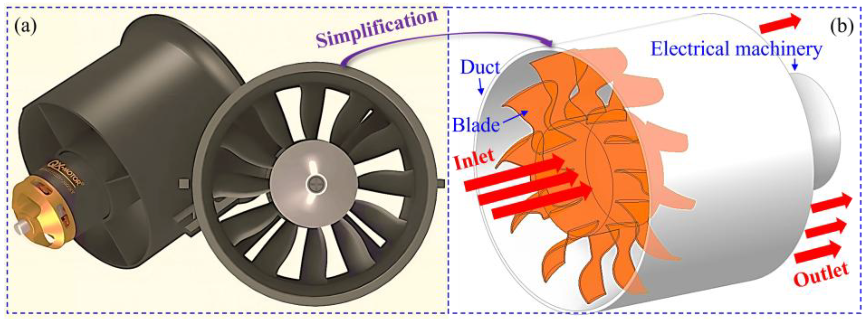
Figure 2.
Boundary condition setup of segmented ducted fan.
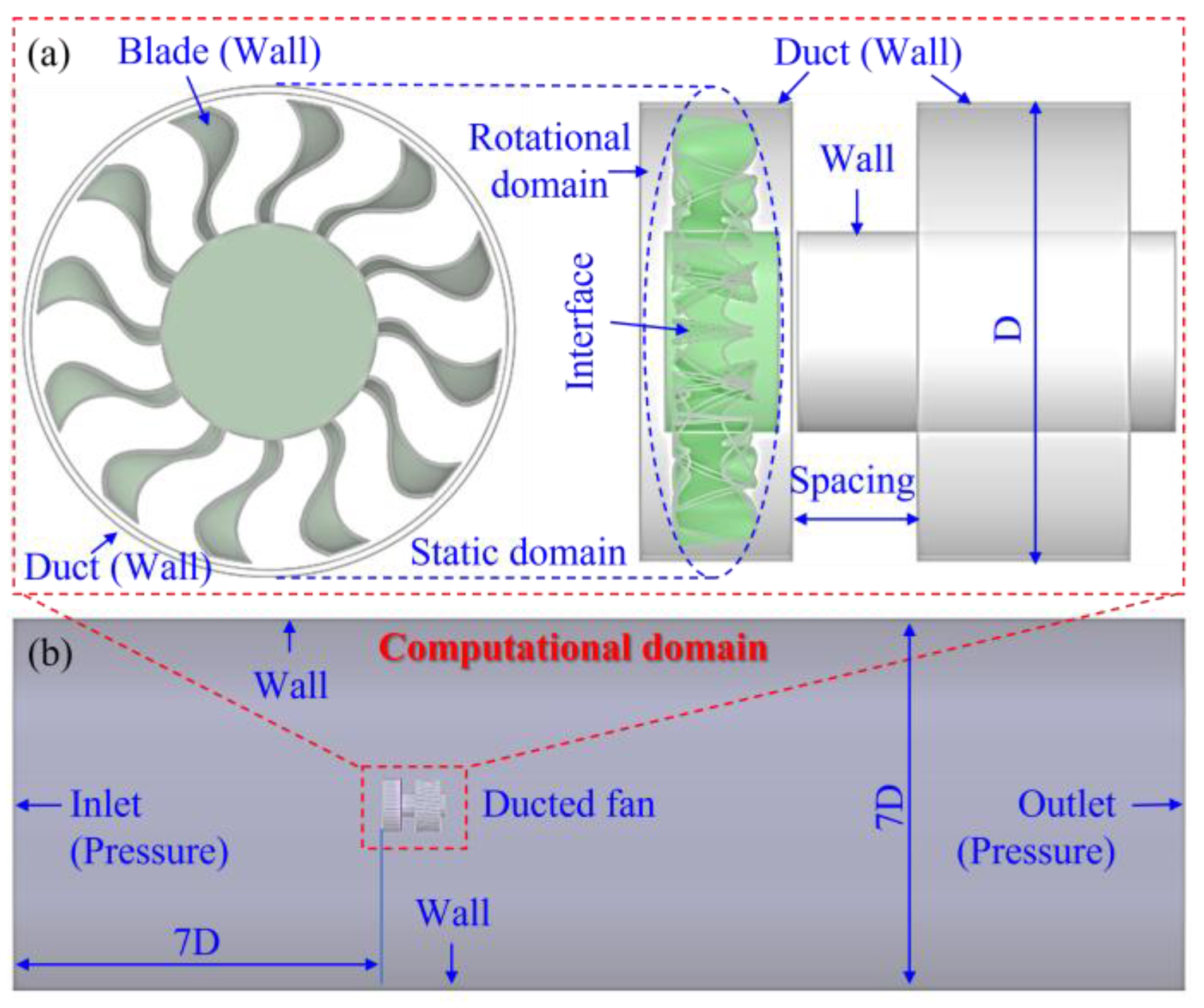
Figure 3.
Schematic diagram of computational domain mesh.
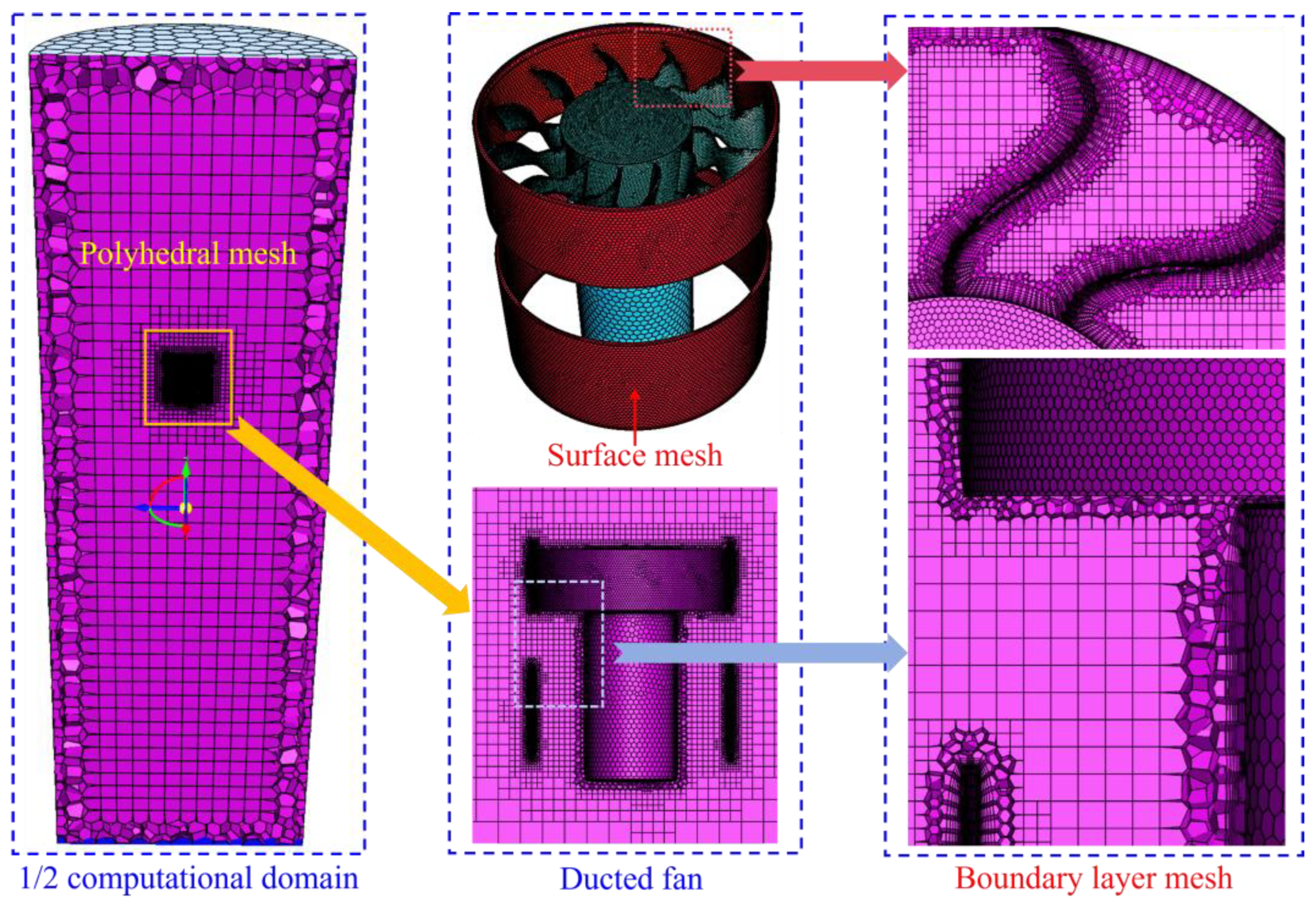
Figure 4.
Influence of fan rotational velocity on noise and flow pressure.
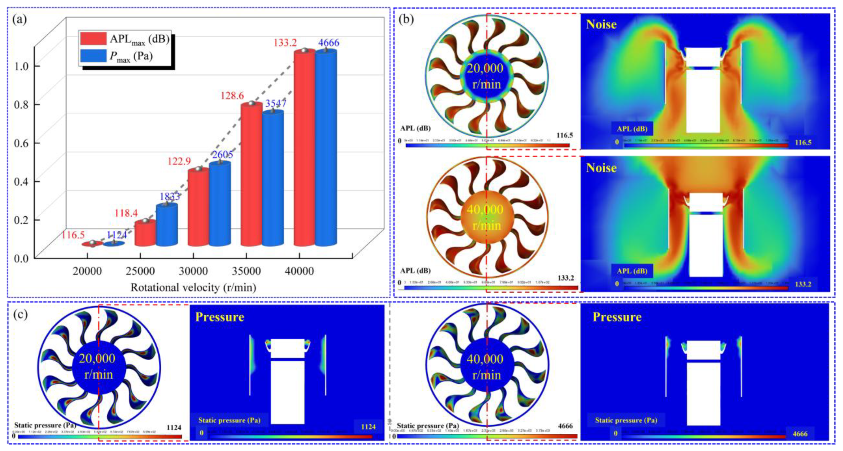
Figure 5.
Influence of fan rotational velocity on noise and flow velocity.
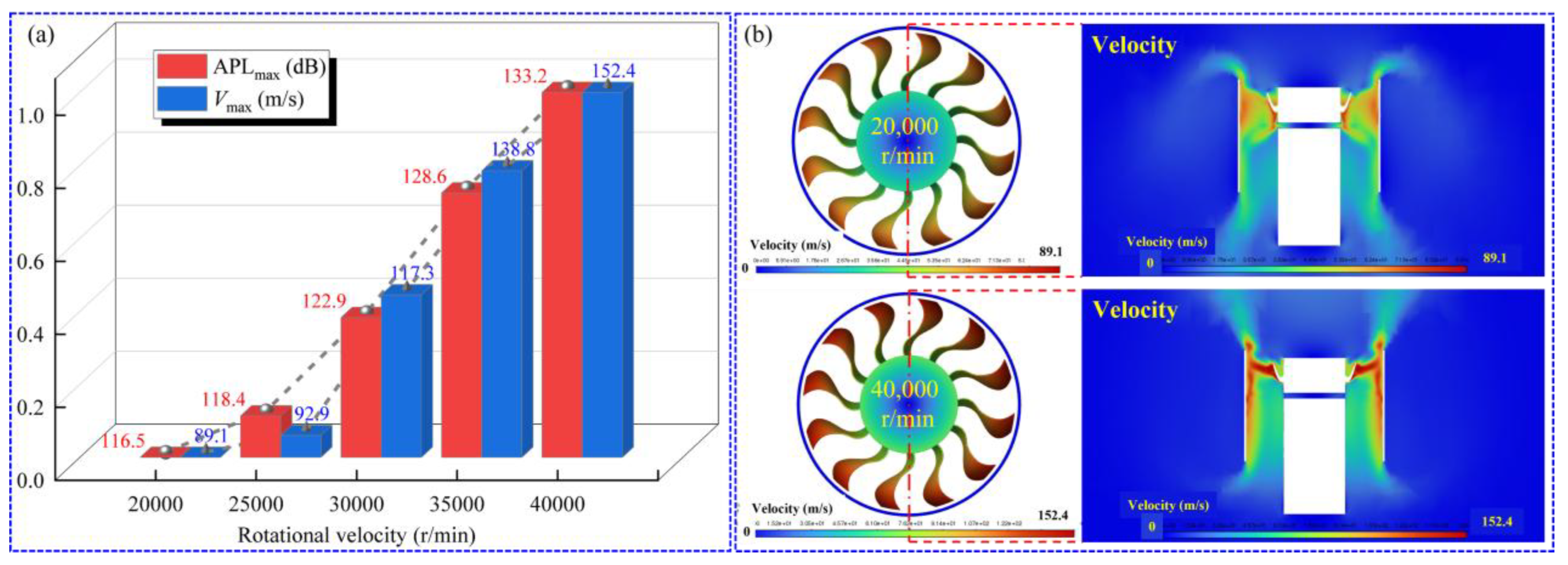
Figure 6.
Influence of duct spacing on acoustic characteristics of ducted fans under different velocities.
Figure 6.
Influence of duct spacing on acoustic characteristics of ducted fans under different velocities.
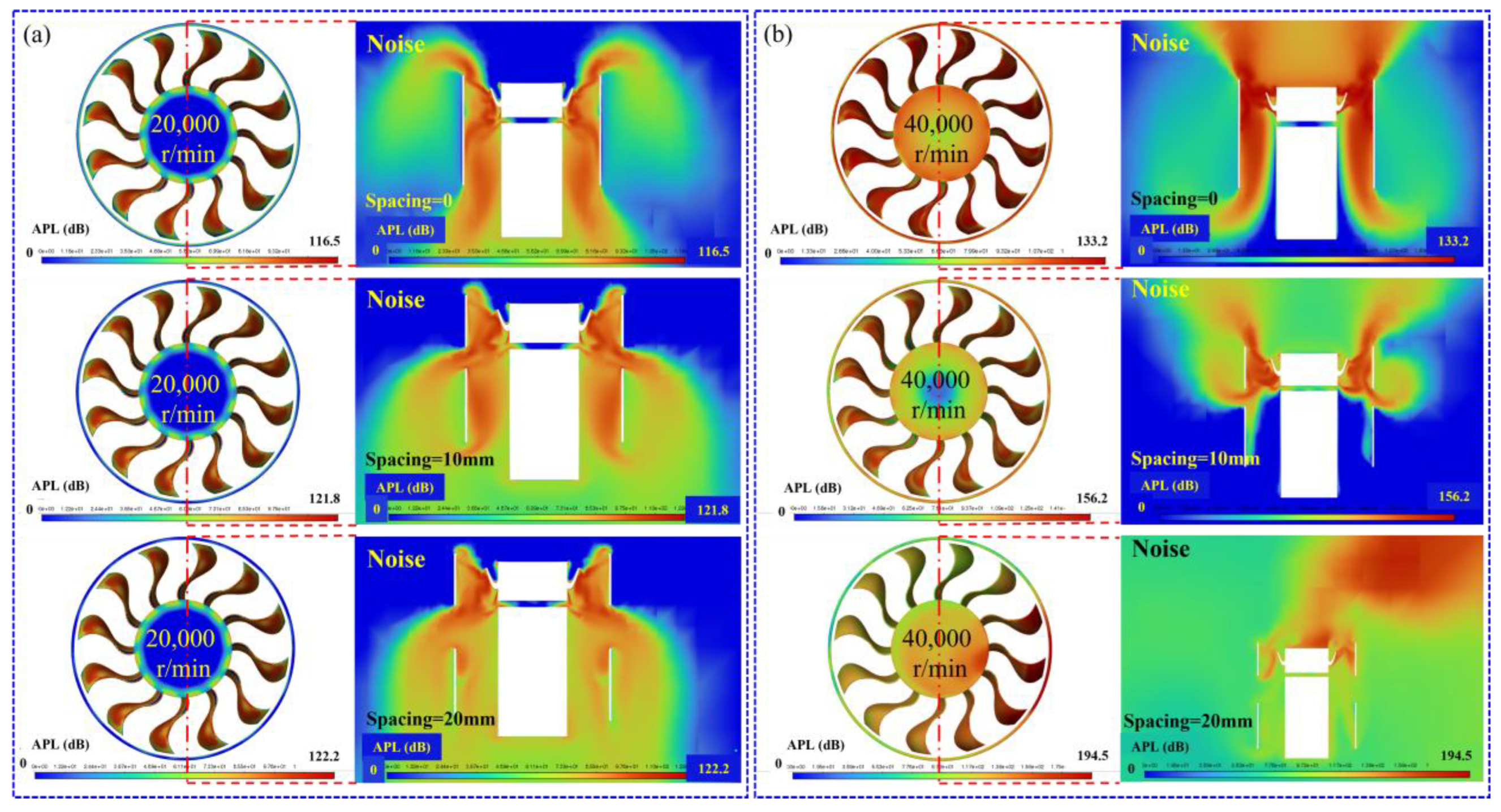
Figure 7.
Influence of duct spacing on flow field pressure and velocity of duct fans at 20,000 r/min.
Figure 7.
Influence of duct spacing on flow field pressure and velocity of duct fans at 20,000 r/min.
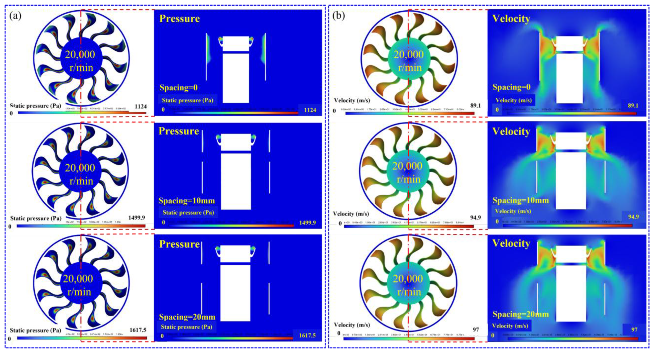
Figure 8.
Influence of duct spacing on flow field pressure and velocity of duct fans at 40,000 r/min.
Figure 8.
Influence of duct spacing on flow field pressure and velocity of duct fans at 40,000 r/min.
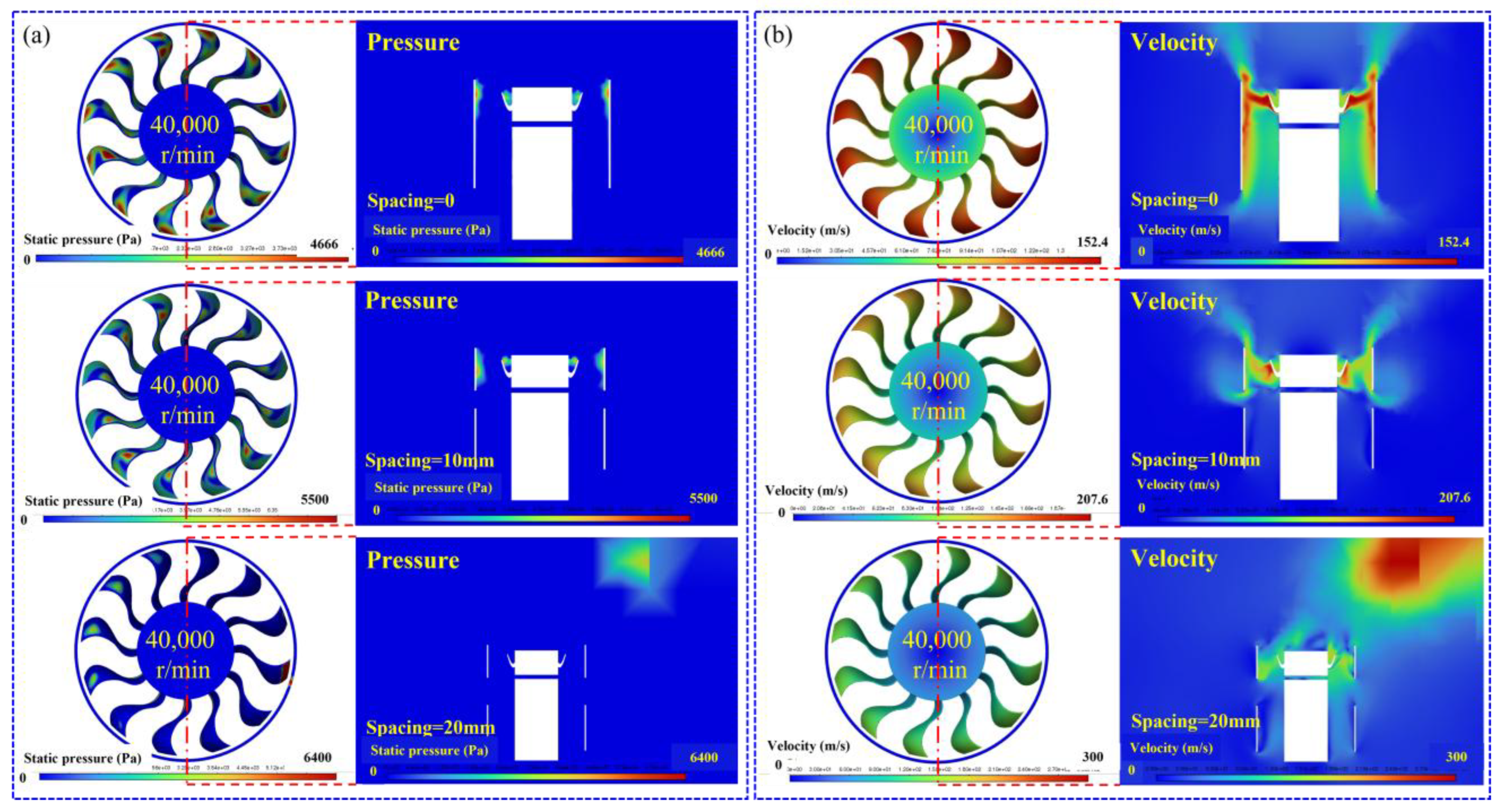

Table 1.
Key parameters of integrated ducted fan.
| Parameters | Values | Unit |
|---|---|---|
| Number of blades | 12 | 1 |
| Blade chord length | 19 | mm |
| Blade twist angle | 15 | ° |
| Inner diameter of duct | 71 | mm |
| Thickness of duct wall | 1 | mm |
| Duct length | 58 | mm |
| Motor diameter | 32 | mm |
Table 2.
Key dimensional parameters and quality indicators of computational domain grid.
| Component | Mesh size (mm) | Orthogonality | Skewness | Draw ratio | Boundary layers | First layer height (mm) | y+ |
|---|---|---|---|---|---|---|---|
| Blade | 0.5-0.7 | 0.85 | 0.15 | 3.2 | 15 | 0.02 | 0.8 |
| Duct | 1.0-1.2 | 0.78 | 0.25 | 4.5 | 15 | 0.02 | 0.8 |
| Electrical machinery | 1.0-1.2 | 0.72 | 0.28 | 5.0 | 15 | 0.02 | 0.8 |
Table 3.
Parameters used for simulation.
| Numerical method | Values |
|---|---|
| Solver type | Pressure-based |
| Velocity formulation | Absolute |
| Time | Steady |
| Models | SST k-ω, Broadband noise sources |
| Cell zone conditions | Fluid-air-constant |
| Rotational velocity (r/min) | 20,000-40,000 |
| Import setting | Pressure |
| Pressure-inlet (Pa) | 0 |
Table 4.
Influence of grid density on noise in ducted fans.
| Ducted fan | Cells | APLmax (dB) |
|---|---|---|
| Integral (Spacing = 0 mm) | 1,492,353 | 118.3 |
| 1,349,407 | 117.9 | |
| 1,220,678 | 117.3 | |
| 1,044,801 | 116.5 | |
| Spacing = 10 mm | 1,435,971 | 123.1 |
| 1,343,231 | 122.8 | |
| 1,272,171 | 122.5 | |
| 1,243,540 | 121.8 | |
| Spacing = 20 mm | 1,514,198 | 123.2 |
| 1,366,122 | 122.9 | |
| 1,325,645 | 122.7 | |
| 1,211,937 | 122.2 |
Table 5.
Influence of duct spacing on acoustic characteristics of ducted fans.
| Rotational velocity (r/min) | Spacing=0, APLmax (dB) | Spacing=10mm, APLmax (dB) | Spacing=20mm, APLmax (dB) |
|---|---|---|---|
| 20,000 | 116.5 | 121.8 | 122.2 |
| 40,000 | 133.2 | 156.2 | 194.5 |
Disclaimer/Publisher’s Note: The statements, opinions and data contained in all publications are solely those of the individual author(s) and contributor(s) and not of MDPI and/or the editor(s). MDPI and/or the editor(s) disclaim responsibility for any injury to people or property resulting from any ideas, methods, instructions or products referred to in the content. |
© 2025 by the authors. Licensee MDPI, Basel, Switzerland. This article is an open access article distributed under the terms and conditions of the Creative Commons Attribution (CC BY) license (http://creativecommons.org/licenses/by/4.0/).
Copyright: This open access article is published under a Creative Commons CC BY 4.0 license, which permit the free download, distribution, and reuse, provided that the author and preprint are cited in any reuse.


