Submitted:
03 August 2025
Posted:
05 August 2025
You are already at the latest version
Abstract
Spun piles adjacent to pile cap need sufficient confinement to ensure the formation of plastic hinges during severe earthquakes. However, the high confinement ratio required for precast piles according to ACI 318-19 results in tightly spaced spirals, which are difficult to implement. Since higher confinement is only needed at specific regions of the pile, external transverse reinforcement using steel jacketing has been proposed as an alternative solution. An experimental and numerical study was conducted to evaluate the effectiveness. The experimental results showed that the jacket enhanced both the strength and energy dissipation of the connection, but had only a minor effect on its ductility. A parametric study using finite element analysis was performed to investigate the parameters influencing connection behavior. The results indicated that variations of jacket thickness did not significantly impact the connection's performance. A jacket height equal to 1.5 times the pile diameter was found to be the maximum effective length. It was also observed that higher axial loads led to a sudden loss of connection strength, thereby reducing ductility. Partial bonding between the jacket, grout, and pile was found to be acceptable within a certain range. Different from the experiment, the numerical analysis found that the steel jacket increasae the ductility.
Keywords:
spunpile connnection
; steel jacket
; strength
; ductility
1. Introduction
Spun piles are widely used in Indonesia for bridge and wharf foundations. The piles have been produced with limited confinement below the minimum standards since it is design based on elastic concept where the damages are inhibited. The design code (SNI 8460:2017) for sub-structures still adopted elastic method. However, in term of concrete pile detailing, it refers to upper structure code (SNI 2847:19/ACI 318:2019) where at potential plastic hinge, confinement should be fulfilled. Hence, the spun pile and pile cap connection requires adequate confinement, as it experiences the highest curvature. Post-severe-earthquake observations have reported several damages occurring in the pile close to the pile [1]. Therefore, the spun pile at this location must be equipped with adequate confinement. Since it refers to two different standards with different concepts, the requirement for confinement in spun piles in Indonesia is not strictly enforced. As a result, spun piles with low confinement have been widely used in bridges and pier infrastructures across Indonesia.
Recent seismic hazard assessments indicate an increase in seismic acceleration across many regions of Indonesia. Allowing inelastic behaviour to piles in the future becomes a real concern when a major earthquake occurs. This highlights the need to implement performance based design for substructures. Therefore, ensuring adequate confinement in spun pile connections becomes essential. Confinement plays a crucial role in restraining concrete, allowing it to develop fcc’, which enables the structure to sustain large displacement during a major earthquake. The provision of confinement in the plastic hinge area should correlate with the ductility of the structure and its energy dissipation capacity during an earthquake.
Several studies have been conducted in Indonesia to investigate the behavior of spun piles with limited confinement [2,3,4]. An experimental study on three spun pile specimens with a volumetric ratio of 0.24%, which is about 25% of the minimum requirement according to ACI 318:2019 [2] was performed. The spun pile had a diameter of 400 mm, a wall thickness of 70 mm, and a concrete strength (fc’) of 54.4 MPa, with stirrups having a yield strength (Fy) of 681 MPa. The bending test results showed that 3.2 mm diameter stirrups with 100 mm spacing were unable to prevent concrete spalling. Therefore, the reserach was concluded that the existing spun pile configuration is not recommended in high-seismic-risk areas.
Another experimental study was conducted on the connection between spun piles and pile caps using a typical connection type commonly used in Indonesia [4]. A 450 mm diameter spun pile with an 80 mm wall thickness was connected to the pile cap with an anchorage length of 500 mm embedded into the pile cap, with an additional 200 mm bent at a 30-degree angle. Therea are three spun pile to pile cap connections in the experimental study: an empty spun pile (SPPC01) and two spun piles with concrete infill (SPPC02 and SPPC03), both reinforced with 6D19 bars. SPPC03 used expansive concrete to ensure better bonding between the infill concrete and the spun pile and SPPC02 used reguler concrete. All three specimens were subjected to cyclic horizontal loading, with a constant vertical load of 0.1fc’Ag applied during testing. The results indicated that the connections exhibited relatively ductile behavior, with a ductility value of 3.7 for the infilled spun pile connections and up to 5 for the empty spun pile. The strength of the spun pile with concrete infill and 6D19 reinforcement increased by 41% compared to the empty spun pile connection. However, despite its higher ductility, the empty spun pile failed to reach the target drift of 3.5%, failing at 2.75% drift instead. The test results also revealed fracture in the prestressing strands at a location 30 mm – 50 mm outside the pile cap. Overall, the experimental study demonstrated that spun piles with minimum confinement performed reasonably well, although they exhibited limited ductility and pinched hysteretic curves. The spun pile with 6D19 reinforcement showed significant strength improvement compared to the empty spun pile, with better energy dissipation performance.
On the other hand, an experimental study on spun pile-to-pile cap connections was also conducted in China, where the spun piles used had sufficient confinement [5]. A total of six specimens with different connection configurations were tested, representing common connection types used in China. The 500 mm diameter spun piles with a 100 mm wall thickness were made of 80 MPa concrete and were connected to the pile cap using anchor bars welded to steel plates attached to the surface of the spun pile. Additionally, two specimens with different connection details where the spun pile was filled with reinforced concrete and the rebars were anchored 500 mm – length into the pile cap. These connections which are labelled as CT4 and CT5 are similar to the connection type in Indonesia. Though the volumetric ratios were not mentioned but based on the data, the spun pile had transverse reinforcement slightly lower than the minimum standard. The piles used D4 – 50 mm for spiral which is equivalent to 0.43% of confinement where the minimum requirement refer to ACI was 0.623%. All specimens were subjected to a constant vertical load of 0.1fc’Ag and cyclic horizontal loading. The results indicated that the ductility values of the connections ranged between 3 and 4. Specimen PC5 exhibited the best performance in term of its ultimate Moment and ductility. Overall, the hysteretic curves also showed pinching behavior. This study demonstrated that the performance of a better confinement spun piles in China was not significantly different from the spun piles with poor confinement tested in Indonesia, in terms of ductiliy.
The experimental study on spun pile-to-pile cap connections in Korea, conducted by Bang, utilized spun piles with a diameter of 500 mm, a wall thickness of 80 mm, and fc’ of 80 MPa [6]. The study compared three different pile head treatment. PHC-A and PHC-B were reinfoced by 9 PC bars with 9.2 mm diameter, meanwhile PHC-C had 12 PC bars of 8.3 mm-diamater. The pile head treatment of three connections were different. The pile of PHC-A was fully embedded to the pile cap with 500 mm length. PHC-B was similar to the the connection type in Indonesia by removing only the concrete of the pile without cutting the PC bars. The pile was filled by reinforced concrete of fc’24MPa and 9D19 deformed bars where the anchorage length of 920 mm. PHC-C has similar pile head treatment with PHC-B with additional transverse reinforcement. The study found that different pile head treatment resulted different connection performance. PHC-A has the highest initial rigidity but the lowest bending capacity. PHC-C which has additional transverse reinforcement has the highest energy dissipation and bending capacity.
Due to the uncertainty of the hard soil position, ensuring confinement in the spun pile at the connection area can be achieved by providing external confinement. This option is more efficient as it can be customized to suit the connection location rather than adding spiral reinforcement along the entire length of the pile. Concrete jacketing, steel jacketing, or FRP wrap are three commonly used confinement methods.
A 50 mm-thick concrete jacketing in the connection area of spun piles was conducted to strengthening the connection [7]. The spun pile had a diameter of 500mm, a wall thickness of 100mm, and a concrete strength of fc’ 80 MPa. The spun pile was reinforced with ten 7mm-diameter strands and spiral reinforcement of D4 – 50mm with a confinement ratio of 0.43%. The specimen was subjected to a constant vertical load of 0.1fc’Ag and cyclic horizontal loading. The experiment demonstrated a more robust hysteretic curve with the ductility value increasing from 3.07 for specimens without strenghening to 4.5. Additionally, the connection strength increased by 54.4% compared to the unreinforced connection. The study concluded that concrete jacketing significantly improves connection performance. Nevertheless, the application of concrete jacketing as a strengthening technique is difficult to implement in foundation systems.
Yang conducted an experimental study on the spun pile–pile cap connection by applying three layers of FRP with a height of 800 mm to the spun pile in the connection area [8]. The spun pile used had a diameter of 500 mm, a wall thickness of 100 mm, and a concrete strength of fc’ 80 MPa. The piles use stirrups of 5 mm in diameter with 80 mm spacing, which lead to a confinement ratio of 0.245%. The experimental study showed a more robust hysteretic curve; however, the ductility did not improve which was 2.30. The presence of CFRP had minimal effect on the connection ductility.
Research on steel jackets as a strengthening method has been widely conducted on column structures [9,10,11,12]. Steel jackets can provide confinement similar to continuous hoop reinforcement. Columns strengthened with steel jacketing exhibit higher strength and ductility. In conclusion, the study found that steel jackets significantly improve the initial stiffness, strength, ductility, and energy dissipation of columns.
Recent seismic hazard assessments indicate an increase in seismic acceleration across many regions of Indonesia. The potential for damage to piles in the future during major earthquakes has become a serious concern. This highlights the need to implement performance-based design for substructures. Therefore, ensuring adequate confinement in spun pile connections is essential. It is necessary to find an external confinement solution that is customized to the diameter of the spun pile, easy to construct, and cost-effective.
A numerical study on the use of steel jackets as external confinement for spun piles in the connection area has been conducted [13]. The validation of the FE model using Abaqus was performed based on the experimental study conducted by Wang. Parametric variations in steel jacket thickness demonstrated that steel jackets provide additional strengthening and also enhance the ductility of the connection. The use of concrete jacketing requires formwork during construction, making it less practical. Steel jacketing made from hot-formed steel has limitations in terms of diameter and thickness. FRP offers advantages in constructability but is relatively expensive. This study proposes a steel jacket made from cold-formed steel as an alternative external confinement. Besides being cost-effective, its thin profile allows for customization of the diameter to match the spun pile.
The innovation of steel jacket and the associated construction methods have been registered with the Indonesian Patent [registration number P00202109462]. An experimental study has been conducted to ensure the construction process and the effect of steel jacketing to the spun pile connection behaviour [14]. The jacket improves the connection’s deformability and boosts the energy dissipation capacity by 1.8 times compared to a connection without the steel jacket. Additionally, it increase the bending strength by 18%. Those results showed that the steel jacket can be used as a promising alternative solution to fulfill the confinement of the spun pile on the connection area since it improve dissipated energy of the connection. This paper report further numerical study based on finite element analysis to investigate parameters that affect the behavior of the connection. Brief description of previous experimental study was reported.
2. The Experimental Programs
2.1. The Specimens
Three full scale spun pile connections strengthened with a steel jacket were prepared to evaluate their seismic performance. The comprehensive discussion and results were reported [14]. The specimens SPPC05, was an empty spun pile, SPPC06 was filled with concrete, meanwhile SPPC07 had reinforced concrete infill. The steel jacket was cold-formed steel plate with 0.5 mm thick which was bent to match the diameter of the spun pile. Rivets were utilized to connect the end. The height of the jacket was 850 mm which was equal to the length of the concrete crack damage on the spun pile of first series testing.
Figure 1 shows the detail of spun pile and the pile cap connection. A 450 mm diameter spun pile with an 80 mm wall thickness was employed. It was made of fc’ 50 MPa concrete strength and reinforced with 10 strands of 7.1 mm prestressed wire. It was confined by a 4 mm diameter spiral with a pitch of 120 mm. SPPC06 is similar to SPPC07 without the presence of 6D19. The pile cap dimension was 1700 x 1200 x 700 mm which was constructed by fc’ 30 MPa and reinforced by 1% of reinfoced bar. The spun pile was embedded into the pile cap to a depth of 100 mm. The anchoraged length of the prestressed concrete (PC) wire to the pile cap was determined according to ACI 318-14M, where the required length was 540 mm. To reduce the depth of the pile cap, the length was made of 500 mm straight with an additional of 200 mm bended at 30 degrees. The details are shown in Figure 2. Table 1 present the steel reinforcement.
The minimum confinement ratio according to ASCE 7-16 for a 450 mm diameter spun pile loaded with 0.1f’c Ag axial load is 0.768%. Meanwhile, a ratio of spiral with 4 mm diameter and 120 mm spacing is 0.113%, which is only 13% of the minimum requirement. A 5 mm thickness of the steel jacket provided additional confinement and hence the confinement ratio of the spun pile on the connection zone increased to 0.56%. The amount is slightly lower than the requirement. Concrete grout with 25 mm thick made of fc’ 61 MPa was attached to the pile to transfers the force from pile to the jacket.
2.2. The Set-Up
Figure 2 presents the test set-up. The specimen was attached to a strong floor with 10 anchoring bolts. Seven transducers were installed to measure horizontal displacement of the spun pile and two transducers were aimed to measure the vertical displacement. The movement of the pile was captured by another to transducers (Tr-19 and Tr-20). The speciments were tested following the loading protocol specified by ACI 437-07 as shown in Figure 3. The targeted drift was 3.5%. A constant vertical load of 500 kN which was equal to 0.1f’cAg was applied. The jack was attached to a sliding frame to ensure the verticallity of the load. The test was terminated upon reaching the target drift or a strength degradation exceeding 50%, whichever condition occurred first.
2.3. The Results
The failure mode of three specimens is presented in Figure 4 and Figure 5. Specimens SPPC05 and SPPC06 failed earlier due to the detachment of the steel jacket connection at a drift of 1.75%. The placement of the steel jacket connection on the spun pile was not purposely arranged. For SPPC05 and SPPC06, the connections located approximately 30 degrees from horizontal load path. Once the connection of steel jacket failed, debonding occurred between the jacket and the concrete grout as well as between the grout and the spun pile, as shown in Figure 4. The debonding breaks forth from the farthest part from the pile cap surface and spread downward. When the connection began to fail, the confinement from the steel jacket was revealed to be still effective on the lower side. Therefore, the failure of the steel jacket did not result in a sudden loss of strength in the connection as can be seen on the histeretic curves presented in Figure 6a and 6c. Another failure mode observed on SPPC06 was buckling of the steel jacket next to the pile cap. The buckling indicated that the steel jacket loss the lateral support due to debonding from the grout. Interestingly, fracture of the PC wire was also detected during the testing, indicated by the sound of the bar breaking in all three specimens.
SPPC07 was the only specimen where the steel jacket performed without the failure of its connection since it was located perpendicular to the horizontal loading path. Hence, the spun pile in the connection zone had sufficient confinement throughout the testing. The failure mode of SPPC07 is shown in Figure 5. Cracks occurred on the spun pile outside the steel jacket and on the surface of the pile cap. At the end of the test, fractures in the steel jacket occurred.
The results of the cyclic loading test are presented as the hysteretic curves shown in Figure 6. As shown, the spun pile with steel jackets exceeds the target drift 3.5%, meanwhile SPPC07 even reaching a drift of 5%. SPPC06 exhibited asymmetry histeretic curve during push and pull cycles. This was caused by the failure of the steel jacket connection and the different failure modes on each side. Buckling was observed only on one side of the steel jacket. This behavior is reflected in the hysteretic curve and the maximum capacity on both sides is different up to 15%.
The comparison of three specimens, SPPC05, SPPC06, SPPC07, is displayed in the envelope curves shown in Figure 6d. SPPC07 shows better performance in term of of strength and energy absorption. SPPC07 has the greatest capacity because it has additional reinforcement bars (6D19) and also the jacket confines the spun pile throughout the test.
Comparing to the specimen without steel jacket on first series test, the jacket on SPPC07 increase the bending strength by 18% [14]. The specimen shows larger deformability and improve the energy dissipation by 1.8 times. These findings conclude that the steel jacket does not only provide additional confinement thus allowing the connection to deform further, but also contribute to an increase in strength. However, the steel jacket did not improve the ductility of the connection. As the steel jacket was embedded into the pile cap, resulting for development of its tensile strength. Moreover, the adequate bonding between steel jackets with the concrete grout effectively increased the diameter of spun pile from 450 mm to 500 mm. The additional moment arm provided by the steel jacket on the outer side of the spun pile also contributed to the increase of overall strength of the connection.
3. The Numerical Study
A finite element study is used to further investigate the parameters affecting the behavior of connections reinforced with steel jackets. Two parameters are examined: the thickness and height of the steel jacket on connection behavior. Model validation is conducted to ensure that the model accurately represents the experiment.
3.1. The Geometric Model
The FE model utilizes C3D8R solid elements for the spun pile and pile cap concrete. It is a three-dimensional (3D) continum solid element consisting of eight nodes with reduced integration. The concrete infill and its connection to the pile cap use C3D6 elements, which is 3D solid elements consisting of six nodes with. Shell element S4R consisted of four nodes with reduced integration was used to model the steel jacket. All reinforcing bars used T3D2 truss element with 2 nodes. The geometric model and meshing of spun pile to pile cap connections are shown in Figure 7 and Figure 8.
The prestressing force in the PC wire was modeled using a predefined field by applying an initial stress of 0.75 fpu, which was 1080 MPa. Assuming a prestress loss of 20%, the remaining stress was 864 MPa. The prestressing force was assumed linearly increase over a length equal to one pile diameter (1D) or 450 mm. A fixed support is applied at the bottom part of the pile cap to represent the experimental test where the pile cap was anchored with ten 32 mm diameter bolts embedded into a 500 mm thick strong floor.
During testing, 25 mm thick steel plate was placed on top of the spun pile to distribute the vertical load. The steel plate was represented by a reference point (RP) at the center of the top surface of the spun pile, which connected all nodes in that area as a rigid body. This ensured that the applied vertical and horizontal loads acted on the top surface of the spun pile without causing stress concentration.
3.2. The Constitutive Laws of Material
The constitutive law for concrete used the Reddiar model, which was a modification of Mander’s concrete model with post-peak softening phase. The tensile behavior of concrete follows the Wahalathantri et al. (2011) model, which is a modification of Nayal and Rasheed (2006), chosen for numerical simplicity and to avoid errors in Abaqus analysis. The tensile strength of concrete is taken as 0.62√fc’. The Concrete Damage Plasticity (CDP) model is used to simulate the damage in concrete after reaching its maximum strength under both tension and compression.
The constituve law of all reinforcement steel bars such as longitudinal and transverse rebar of concrete infill, transverse rebar of spun pile and reinforcement of pile cap used Park and Paulay’s law. The engineering stress-strain curve were converted into true stress-strain data to account for the reduction in cross-sectional area due to necking. The constitutive model used for prestressing bars follows Thompson and Park. Additionally, the ductile damage failure model is applied to represent the fracture process of the reinforcement.
The interaction between components significantly influences the behavior of the connection. The bond between steel rebars and concrete was modeled as an embedded region, meaning a perfect bond without slip, ensuring that both elements share the same degrees of freedom. The interaction between the spun pile and pile cap, as well as between the spun pile and concrete infill, was defined as hard contact in the normal direction. In the tangential direction, the interaction between the two surfaces was represented using Coulomb friction. Based on the study conducted by [11], the friction coefficient (μ) between two dry concrete surfaces ranges from 0.5 to 0.7. A friction value of 0.5 was used at the interface between the spun pile and pile cap.
3.3. The Comparioson of the FE Results and the Experiments
According to the testing scheme, the vertical load of 0.1fc’Ag and the weight of steel plate, weres applied as a constant uniformly distributed load acting on the top surface of the spun pile. The magnitude was 5.43 MPa for an empty spun pile, and was 3.15 MPa for piles with infill concrete. After the vertical load was applied, monotonic push over analythis was conducted horizontally until a targetted drift of 3.5% or 63 mm.
The results of the FE analysis presented as lateral force versus lateral displacement at top of pile is shown in Figure 6. It is compared to the hysteretic curve of the experimental results of specimens SPPC05 and SPPC07. As observed, the FE analysis closely matches the experiment. The FE model is able to accurately represent the linear phase and the post peak behaviour. The difference of the maximum lateral forces to the experiment of SPPC05 and SPPC07 is only 5.5% and 6.1%, respectively. The failure modes from FE results are similar to the experiment as can be seen on Figure 9, Figure 10 and Figure 11. Fracture of the PC wires, buckling and fracture of the steel jacket were occurred on the FE analysis. Therefore, the models were considered valid and further parametric study could be carried out.
4. Parametric Study
The study focus on the connection of spun pile with reinforcing concrete infill that commonly used in Indonesia which was similar to SPPC07. The aim as to find out the parameters that affected the strength and the ductility of the connection, two important parameters that used to describe the behaviour of the connection. The parameters are: the effect of confinement ratio, the bonding of the steel jacket, concrete grouting and the spun pile, the penetration of steel jacket to the pile cap, the thickness and the depth of the steel jacket and the magnitude of the axiala load.
4.1. The Effect of Confinement Ratio
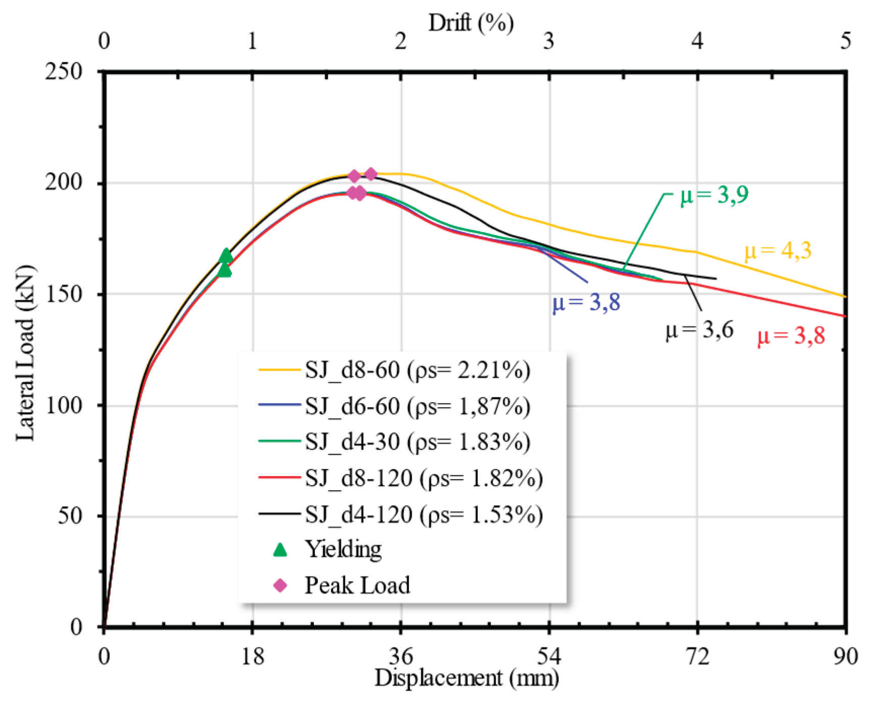
Figure 12 illustrates the influence of the confinement ratio to ductility of five specimens. Figure a shows the comparison of spun pile on five different confinement ratio without steel jacketing where its is varried from 0.59% to 1.83%. The ratios affected by spiral diameter and its spacing. As shown, the ratio affects the post-peak behavior of the connection. The force–displacement curve shows a more gradual decline in specimens with higher levels of confinement. Meanwhile, the piles with limited confinement experiences a more drastic strength reduction. Adequate confinement helps the concrete reach its confined compressive strength (fcc’), preventing a sudden loss of strength at higher deformation levels. This influences the ductility of the connection, although its effect is not significant, as the ductility values remain relatively similar, ranging from 2.7 - 2.9.
Figure b illustrates the behavior of the connection with an identical confinement configuration, supplemented by a steel jacket. The presence of the steel jacket enhances the confinement ratio of the connection. As shown in Figure, the ductility of the connection increase to a range of 3.6 – 4.3. Steel jacket also increase the strength of the connection. This indicates that the jacket provides external confinement to the spun pile, allowing it to sustain post-peak deformation more effectively without a significant loss of strength. As observed, the strength degradation in the spun pile with a jacket is more gradually compared to the spun pile without a steel jacket. The use of a steel jacket as an external confinement was found to enhance the connection performance more effectively than increasing the amount of spiral reinforcement in the spun pile
Figure 13.
Load-diplacement curve of different confinement ratio of the spun pile with steel jacket
4.2. The Effect of Steel Jacket Bonding to the Spun Pile
The contact between the steel jacket, grout concrete, and spun pile plays a crucial role in the behavior of the connection, ensuring effective force transfer among the three components and allowing the steel jacket to provide optimal confinement. Experimental studies have shown that when the steel jacket detaches from the spun pile, its role as confinement is lost, significantly reducing its effectiveness in enhancing the connection’s performance.
In the FE model, hard contact is used to represent the experimental conditions, where the friction coefficients are set as follows: 0.8 between the infill concrete and the inner surface of the spun pile, 0.5 between the outer surface of the spun pile and the grout, and 0.3 between the grout concrete and the Zincalume surface. In the fully bonded specimen, it is assumed that the steel jacket is perfectly bonded to the grout concrete, and the grout concrete is perfectly bonded to the spun pile. As observed from the force-displacement curve in Figure 14, perfect bonded enhances the strength of the connection. However, in terms of ductility, partially bonded results in a gradual post-peak strength reduction, leading to better ductility. This condition can be explained by observing the stress development in the inner stirrups as shown in Figure 15. When the bonding is perfect, the stress in the stirrups does not reach the yield stress, indicating that the concrete stress has not fully reached fcc’. In contrast, the stirrups reach their yield stress for specimen with partially bonded, and hence the concrete core within the stirrup is able to reach fcc’. As a result, the post-peak strength degradation is less severe, which theoritically increases the ductility value.
4.3. The Effect of the Steel Jacket Penetration to the Pile Cap
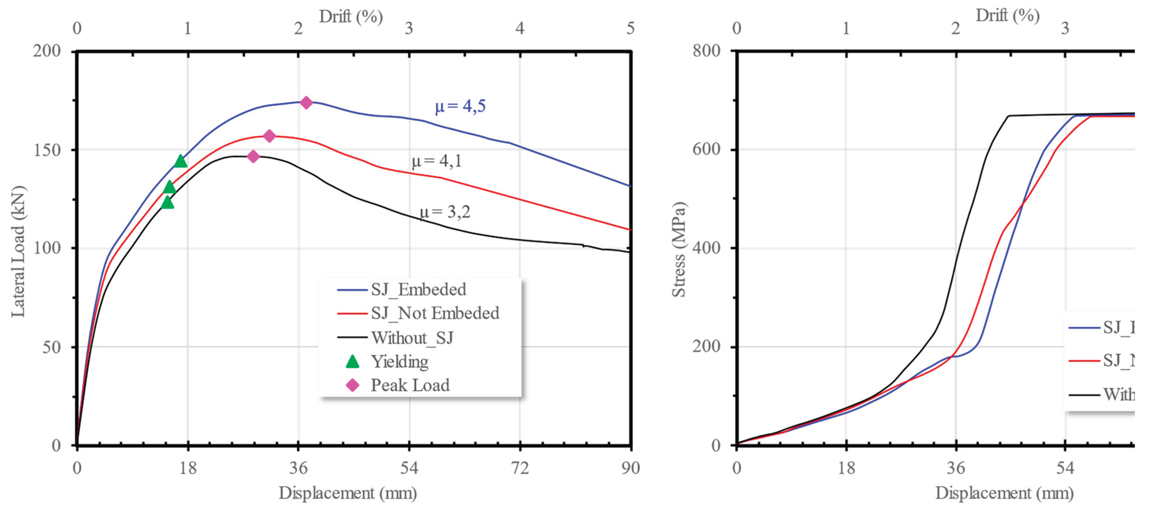
To ensure that the steel jacket provides confinement up to the end of the spun pile, the experimental study penetrate the steel jacket into the pile cap by 100 mm. The FE study compare the effect to the specimen where the jacket stop at the surface of the pile cap and that without steel jaacket. The results are presented in Figure 15. Although the embedment depth is only 100mm, it significantly influences the connection behavior, as the steel jacket not only provides confinement but also contributes to enhance the connection strength.
The connection with an embedded steel jacket has a ductility value of 4.5 whereas the non non-embedded steel jacket has 4.1. Meanwhile the connection without a steel jacket has a ductility value of only 3.2. Referring to the stress development of the stirrups located at the bottom shown on Figure 15b, it can be seen that all three FE models are able to reach yield stress. However, the steel jacket delays the occurrence of yielding of the stirrups compared to the connection without a steel jacket. Therefore the presence of steel jacket increase the ductility since it calculatea as the ratio of the maximum dispacement to the yield displacement.
Figure 15.
The effect of steel jacket penetration to (a) load-diplacement curve and (b) stress development of the bottom stirrup of the spun pile.
Figure 15.
The effect of steel jacket penetration to (a) load-diplacement curve and (b) stress development of the bottom stirrup of the spun pile.
4.4. The Effect of Different Thickness and Height of Steel Jacket
The variation of steel jacket thickness effect to the load-displacement curve is shown in Figure 16. The FE model is based SPPC07 which has steel jacket as a depth of 800mm and penetrate as 100 mm into the pile cap. The contact between the spun pile and concrete infill, as well as between the steel jacket and concrete grouting, are similar to those used in the model validation. Based on the force-displacement curve, the behavior appears to be almost identical. As predicted, a thicker steel jacket increases the structural strength, but the effect is not very significant. There is no significant differences were observed in the ductility of the connection. However, a thicker steel jacket delays the yielding of the spun pile stirrups.
The effect of steel jacket height is shown in Figure 17. All FE models have steel jacket with the same thickness as in the experiment, which is 0.4 mm. The height is varied from 0.67D (300 mm) to 2D (900 mm), where D represents the diameter of the spun pile. Aside from height, the parameters are kept the same as in SPPC07. Unlike the thickness, where its effect becomes noticeable at post yielding, the different height also affect the the elastic phase. As presented in the figure, the changing of height is quite significant at variations of 0.45 to 1.53D. Beyond that value, increasing the steel jacket height does not significantly affect the connection behavior. This observation is supported by the first experimental series, where the plastic hinge was found to form at a height of approximately 700–800 mm, equivalent to around 1.5D. The formation of the plastic hinge was indicated by the crack patterns on the surface of the spun pile in specimens without steel jacketing. Accordingly, it can be concluded that the application of steel jacketing as additional confinement is effective only up to a height of 1.5D.
4.5. The Effect of Different Axial Load
As previously mentioned, an axial load equivalent to 0.1fc’Ag was applied in the experiment to simulate the typical axial load sustained by spun piles at real conditions. According to ASCE provisions, the required confinement in column structures is affected by the magnitude of axial load. In this study, the effect of axial load on the behavior of spun piles was considered as one of the key parameters. Figure 18 presents the effectiveness of the steel jacket for axial load variations of 0.1fc’ag, 0.2fc’Ag and 0.3fc’Ag. From the figure, it can be observed that the axial load signifcantly affects the strength and the ductility of the connection. As the axial load increases, the ductility of the connection decreases. Earlier yileding of the stirrups is observed when the axial load applied on the spun pile is higher.
5. Conclusions
The steel jacket offers an alternative solution to address the lack of confinement of spun piles, particularly given the uncertainty of hard soil. Steel jacket provide external confinement and increase the confinement ratio to meet the required amount set by ASCE provision.
Hasil studi eksperimen menunjukkan steel jacket mampu memberikan tambahan confinement pada spun pile as long as connection dari steel jacket tidak mengalami kegagalan. The penetration of steel jacket with the spun pile into the pile cap develops tensile strength in the jacket, which contributes to the moment capacity of the connection.
Parametric study based on finite element analysis found that the steel jacket effectively provide additional confinement to the pile. It delays yielding of the stirrup of the spun pile. The use of a steel jacket as an external confinement was found to enhance the connection performance more effectively than increasing the amount of spiral reinforcement in the spun pile. An increase in the amount of spiral reinforcement had a negligible impact on the ductility of the connection. In contrast, the application of a steel jacket significantly improved the ductility, raising it from approximately 2.7 to 3.6.
The parametric study found that variations of jacket thickness did not significantly impact the connection’s performance. A jacket height equal to 1.5 times the pile diameter was found to be the maximum effective length. The height corresponds to the length of the concrete cracks observed in the spun pile without a steel jacket. Beyond this height, there is little influence on the connection behavior. The study also found that partial bonding between the steel jacket, grout, and pile was found to be acceptable within a certain range, and even exhibited more ductile behavior compared to fully bonded conditions. The amount of axial load significantly effect the behaviour of the connection. Higher axial loads led to a sudden drop in connection strength, resulting in reduced ductility. Unlike the experimental results, the numerical analysis showed that the steel jacket increased the ductility of the connection.
6. Patents
The steel jacket and the associated construction methods have been registered with the Indonesian Patent [registration number P00202109462] in year 2023.
Author Contributions
Conceptualization, Yuskar Lase and Widjojo Adi Prakoso; Data curation, Mulia Orientilize; Formal analysis, Yuskar Lase; Funding acquisition, Mulia Orientilize and Widjojo Adi Prakoso; Investigation, Mulia Orientilize; Methodology, Yuskar Lase and Widjojo Adi Prakoso; Project administration, Mulia Orientilize; Resources, Mulia Orientilize; Validation, Yuskar Lase, Mulia Orientilize and Widjojo Adi Prakoso; Visualization, Mulia Orientilize; Writing – original draft, Mulia Orientilize; Writing – review & editing, Yuskar Lase and Widjojo Adi Prakoso.All authors have read and agreed to the published version of the manuscript.
Funding
This research is funded by the Indonesia Ministry of Research and Universitas Indonesia through Puti Pascasarjana, contract number NKB-287/UN2.RST/HKP.05.00/2023 and Applied Research Grant, contract number: NKB-254/UN2.RST/HKP.05.00/2021 as part of reasearch collaboration with PT Wijaya Karya Beton, Tbk.
Acknowledgments
The authors acknwledge the contribution PT Wijaya Karya Beton, Tbk which provide materials for experimental program and PT NS Bluescope Lysagh Indonesia for steel jacket materials.
Conflicts of Interest
The authors declare no conflicts of interest.
References
- Kaneko, S. Kawamata, S. Nakai, T. Sekiguchi, and T. Mukai, Analytical study of the main causes of damage to pile foundations during the 2011 off the Pacific coast of Tohoku earthquake. Japan Architectural Review 2018, 1, 235–244. [Google Scholar] [CrossRef]
- C. Irawan, R. Djamaluddin, I. G. P. Raka, Faimun, P. Suprobo, and Gambiro, Confinement behavior of spun pile using low amount of spiral reinforcement - An experimental study. Int J Adv Sci Eng Inf Technol 2018, 8, 501–507. [Google Scholar] [CrossRef]
- Mulia, P. W. Adi, and M. Nadila. Numerical study of low confinement spun pile to pile cap connection. Nadila. Numerical study of low confinement spun pile to pile cap connection. E3S Web of Conferences 2022, 347. [Google Scholar] [CrossRef]
- M. Orientilize, W. A. Prakoso, Y. Lase, S. Purnomo, I. H. Sumartono, and W. Agustin. The Evaluation of Displacement Ductility of Low Confinement Spun Pile to Pile Cap Connections. International Journal of Technology 2023, 14, 823–832. [Google Scholar] [CrossRef]
- Z. Yang and W. Wang. Experimental and numerical investigation on the behaviour of prestressed high strength concrete pile-to-pile cap connections. KSCE Journal of Civil Engineering 2016, 20, 1903–1912. [Google Scholar] [CrossRef]
- J. -W. Bang, S.-J. Oh, S.-S. Lee, and Y.-Y. Kim. Pile-cap Connection Behavior Dependent on the Connecting Method between PHC pile and Footing. Journal of the Korea institute for structural maintenance and inspection 2016, 20, 25–32. [Google Scholar] [CrossRef]
- Z. Guo, W. He, X. Bai, and Y. F. Chen. Seismic performance of pile-cap connections of prestressed high-strength concrete pile with different details. Structural Engineering International 2017, 27, 546–557. [Google Scholar] [CrossRef]
- Z. Yang, G. Z. Yang, G. Li, and B. Nan. Study on Seismic Performance of Improved High-Strength Concrete Pipe-Pile Cap Connection. Advances in Materials Science and Engineering. [CrossRef]
- Y. F. Li, J. S. Hwang, S. H. Chen, and Y. M. Hsieh. A study of reinforced concrete bridge columns retrofitted by steel jackets. Journal of the Chinese Institute of Engineers, Transactions of the Chinese Institute of Engineers,Series A/Chung-kuo Kung Ch’eng Hsuch K’an 2005, 28, 319–328. [Google Scholar] [CrossRef]
- J. Liu, Y. Teng, Y. Zhang, X. Wang, and Y. F. Chen. Axial stress-strain behavior of high-strength concrete confined by circular thin-walled steel tubes. Constr Build Mater 2018, 177, 366–377. [Google Scholar] [CrossRef]
- He, J. Cai, Q. J. Chen, X. Liu, P. Huang, and X. L. Tang. Seismic behaviour of steel-jacket retrofitted reinforced concrete columns with recycled aggregate concrete. Constr Build Mater 2018, 158, 624–639. [Google Scholar] [CrossRef]
- R. Zhang, R. Zhao, Z. Liu, K. Chen, P. Hu, and Z. Liu. Cyclic behavior of existing flexure-dominated RC bridge columns retrofitted by ECC jackets in the region of plastic hinge. Eng Struct 2022, 269, 114820. [Google Scholar] [CrossRef]
- M. Orientilize, W. A. M. Orientilize, W. A. Prakoso, M. Fadel, and R. P. Fernaldy. Study of spun pile connection with steel jacket strengthening. IOP Conf Ser Earth Environ Sci. [CrossRef]
- M. Orientilize, W. A. Prakoso, Y. Lase, S. Purnomo, and I. H. Sumartono. Study of Repaired Spun Pile To Pile Cap Connections Containing Fractured Reinforcements Using Frp. International Journal of GEOMATE 2023, 25, 114–122. [Google Scholar] [CrossRef]
Figure 1.
The detail of three specimens Connection detail, (b) Cut Section A-A: SPPC07; and (c) SPPC05.
Figure 1.
The detail of three specimens Connection detail, (b) Cut Section A-A: SPPC07; and (c) SPPC05.
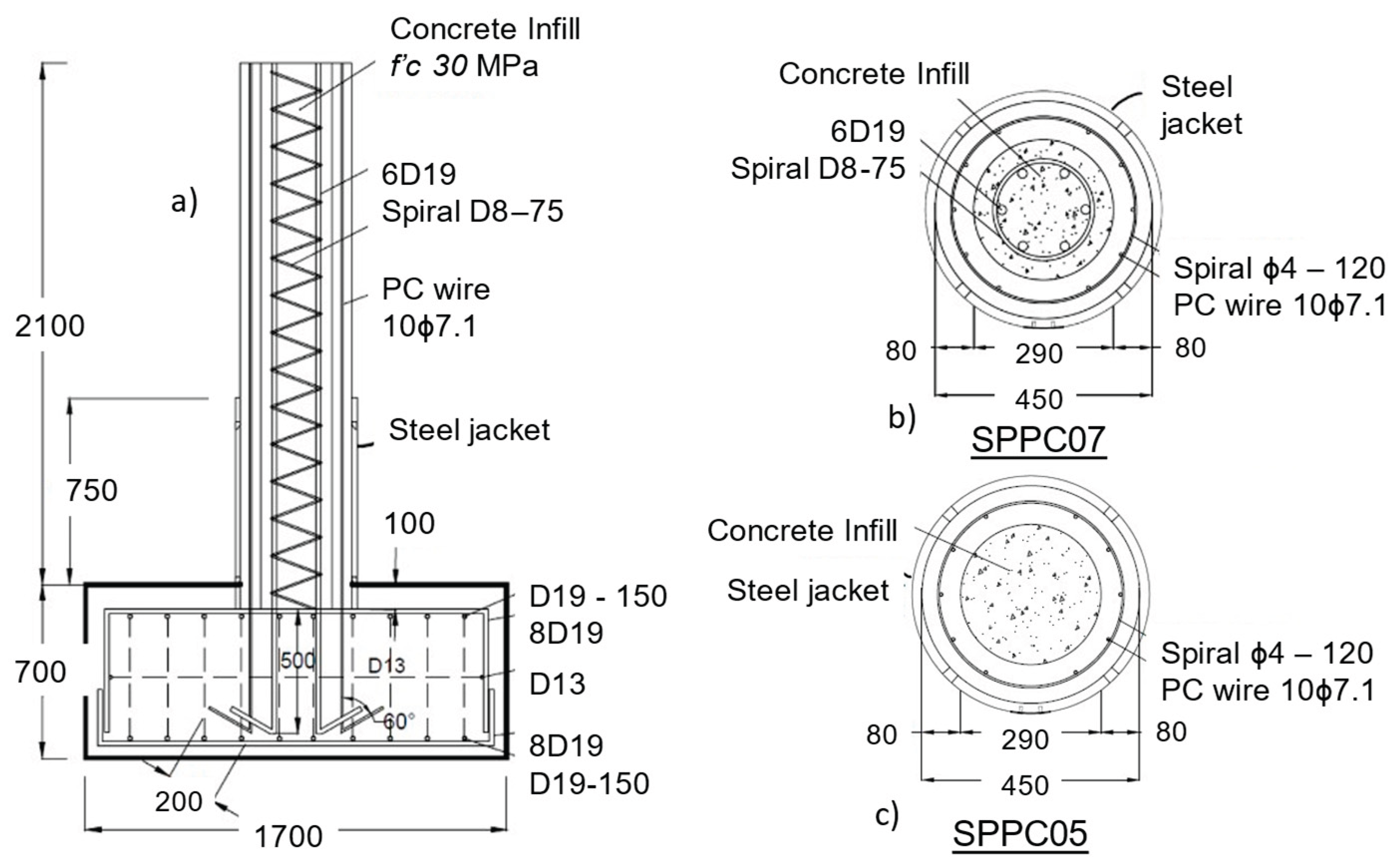
Figure 2.
The Experimental Set-up.
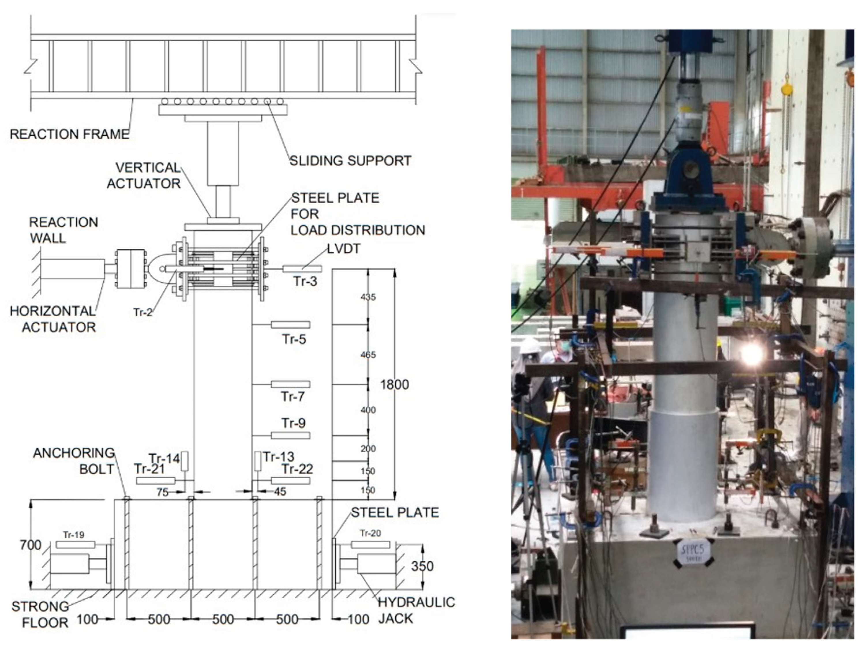
Figure 3.
The Horizontal Loading Protocol.
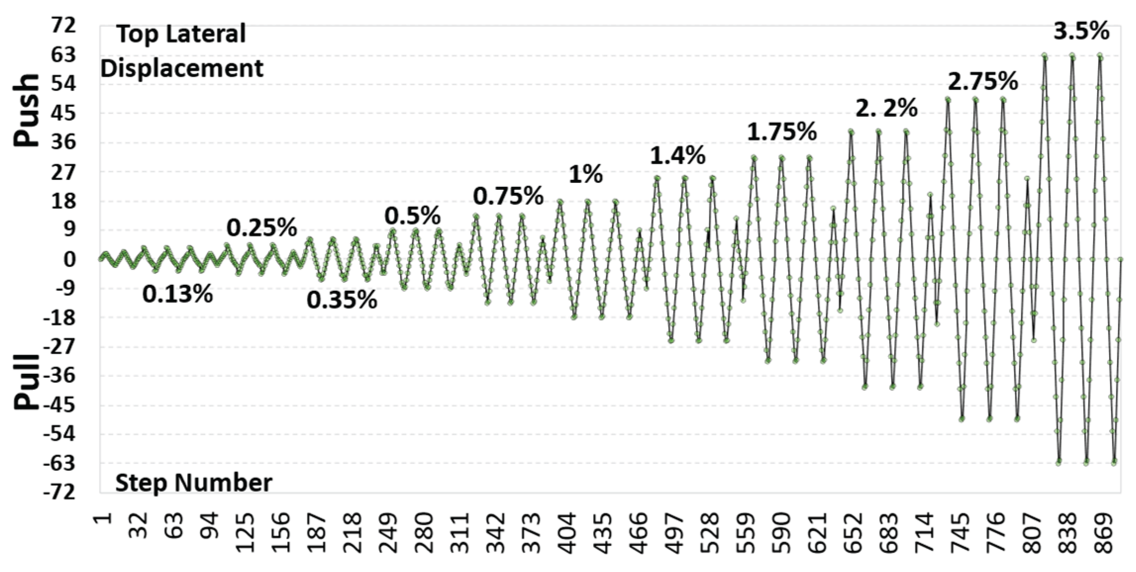
Figure 4.
The Failure mode of SPPC05 and SPPC06.
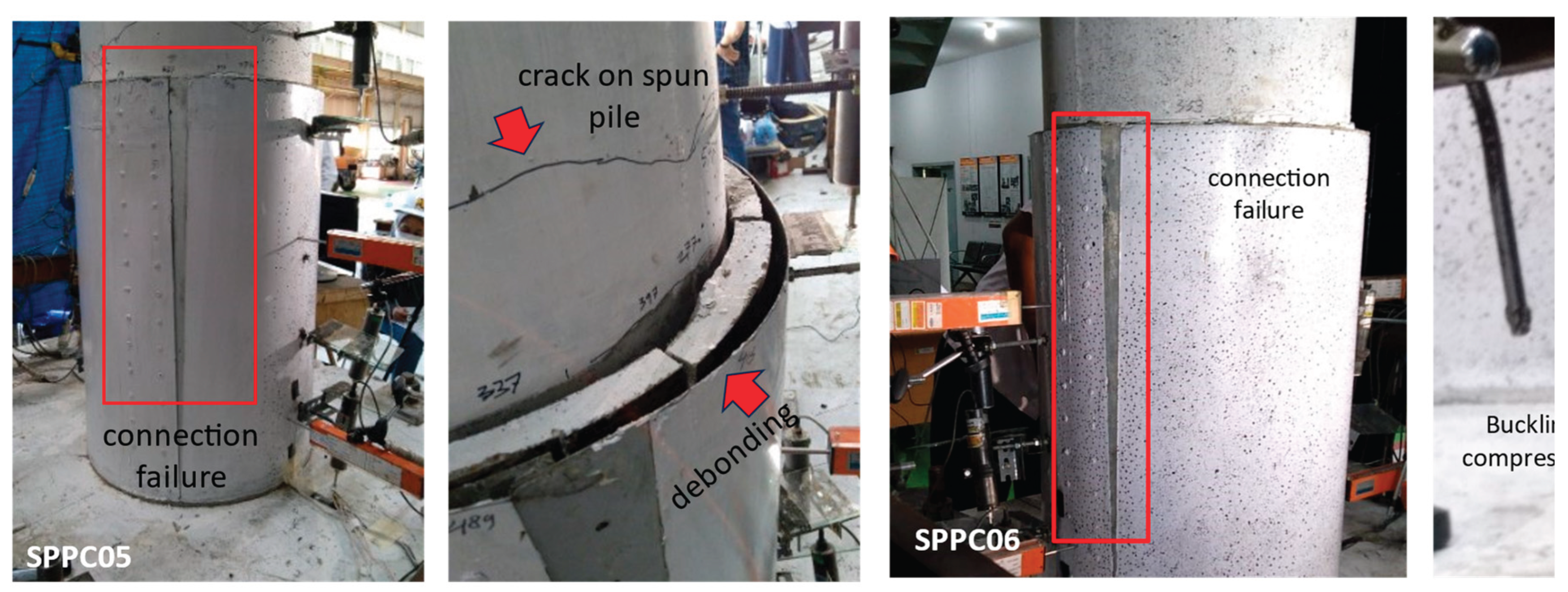
Figure 5.
The Failure mode of SPPC07.
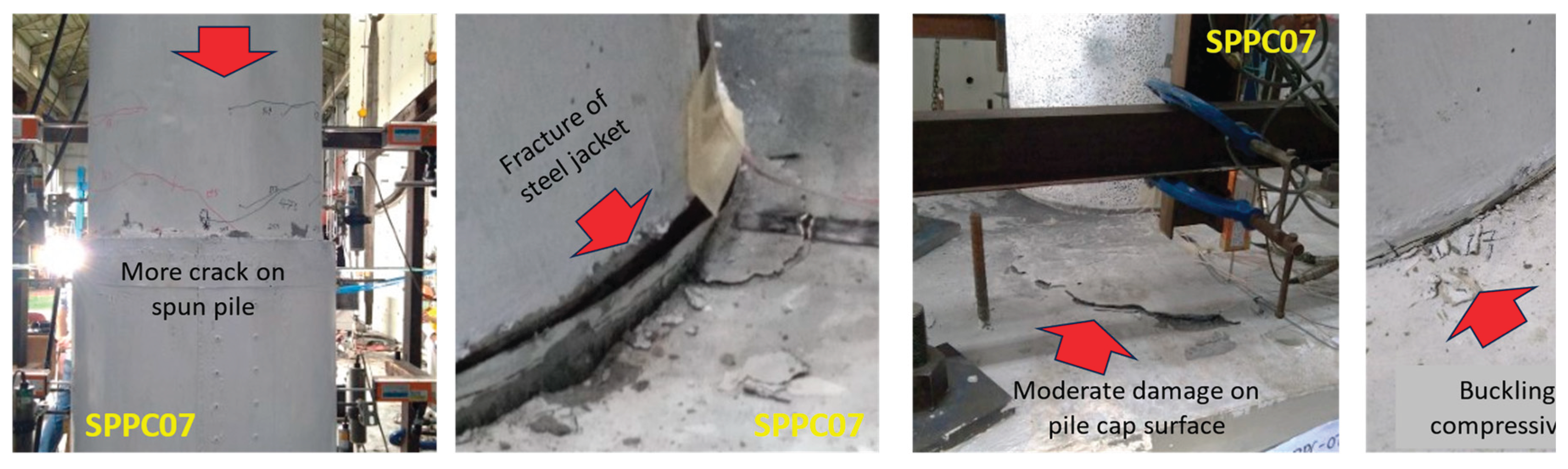
Figure 6.
The hysteretic curve of the experimental results on: (a) SPPC05; (b) SPPC07; (c) SPPC06 and (d) the skeleton comparison of three specimens.
Figure 6.
The hysteretic curve of the experimental results on: (a) SPPC05; (b) SPPC07; (c) SPPC06 and (d) the skeleton comparison of three specimens.
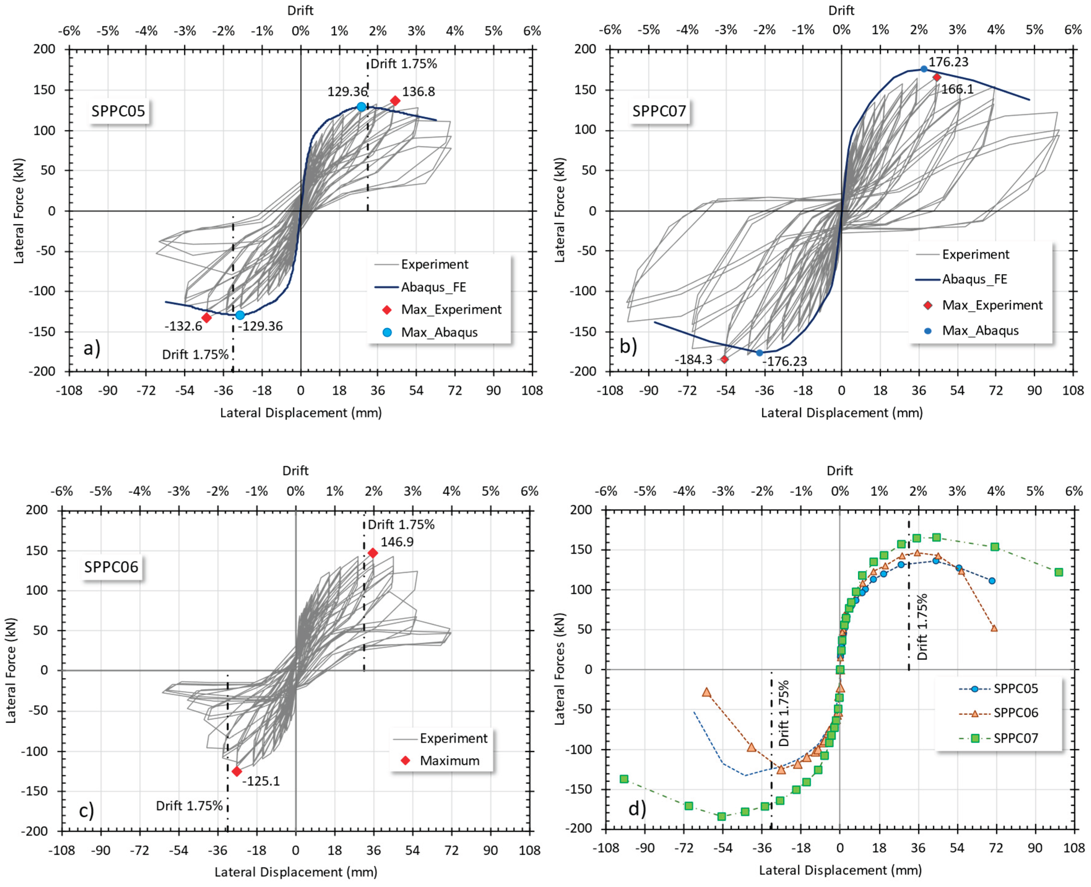
Figure 7.
The geometric model of (a) reinforcing bars, (b) pile cap, spun pile and steel jacket and (c) the FE meshing of spun pile – pile cap.
Figure 7.
The geometric model of (a) reinforcing bars, (b) pile cap, spun pile and steel jacket and (c) the FE meshing of spun pile – pile cap.
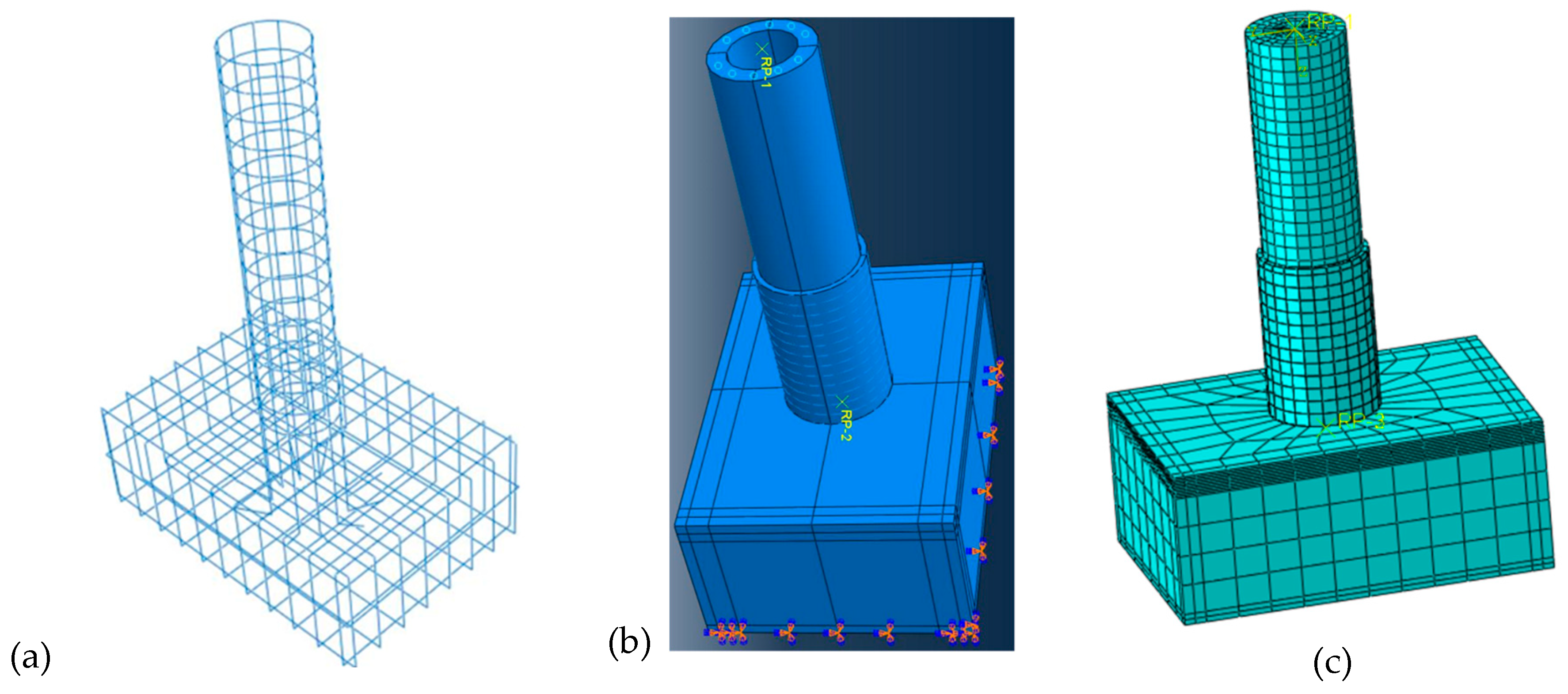
Figure 8.
The meshing of each component of spun pile to pile cap connection .
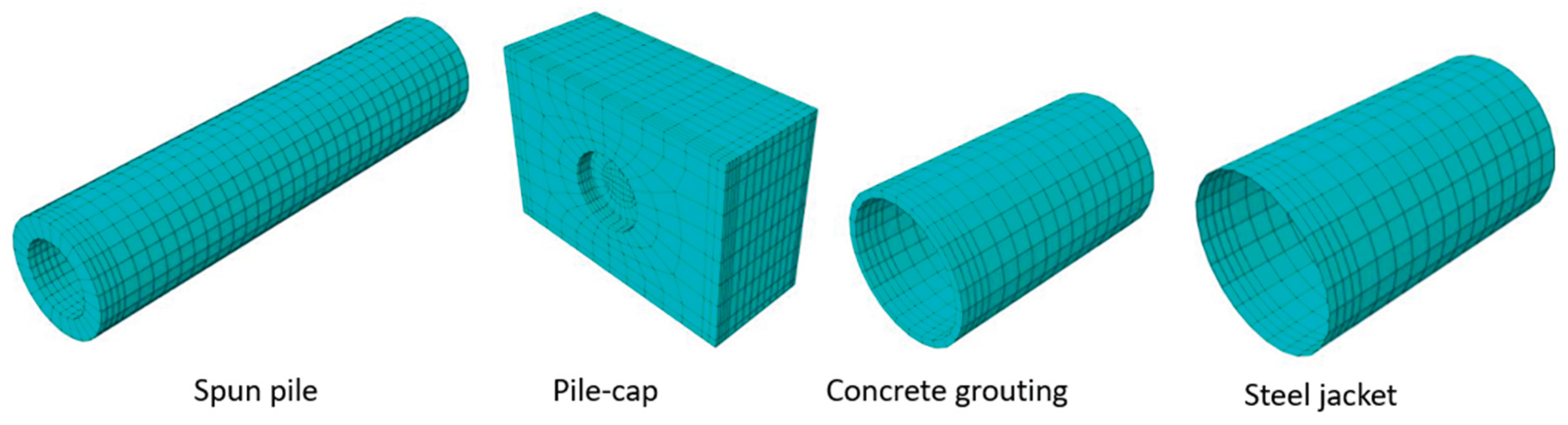
Figure 9.
Stress contour of (a) prestress wire and (b) steel jacket.
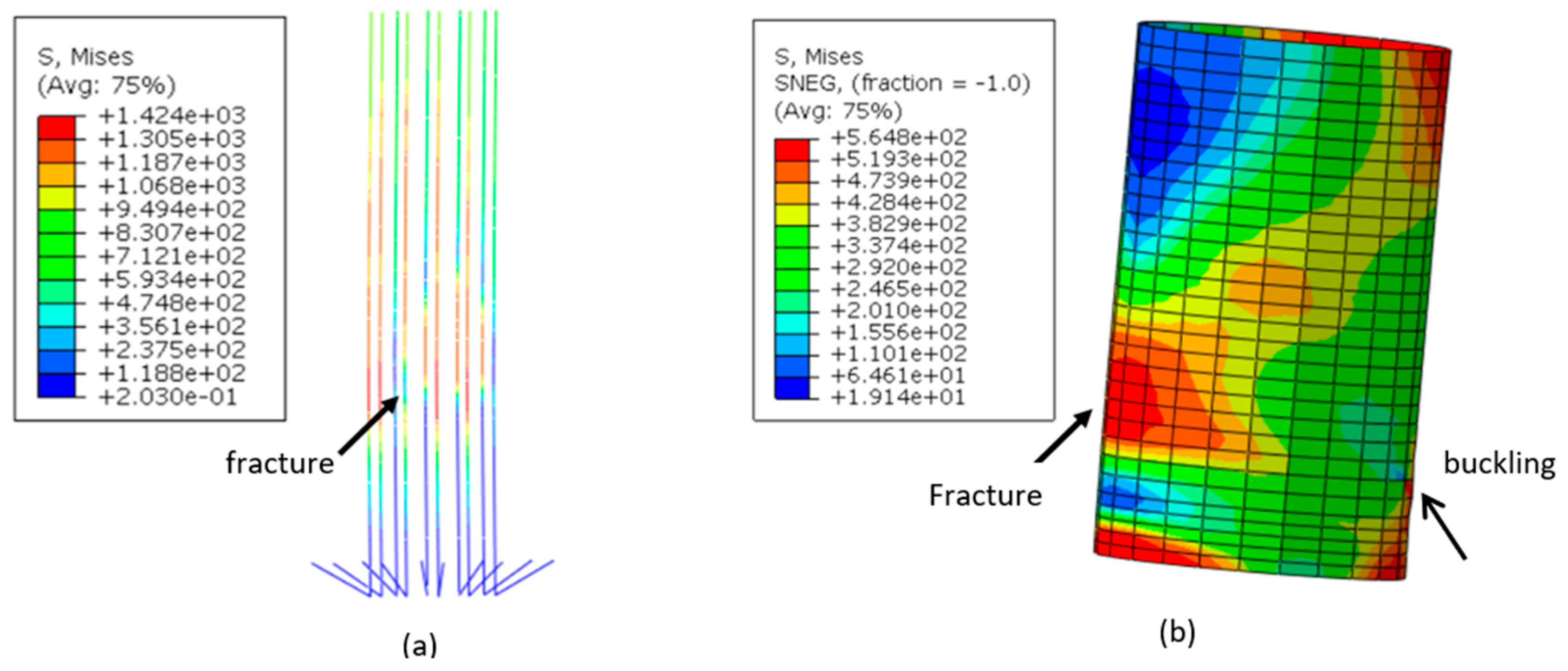
Figure 10.
Compression damage of (a) spun pile, (b) infill concrete and (c) concrete grouting .
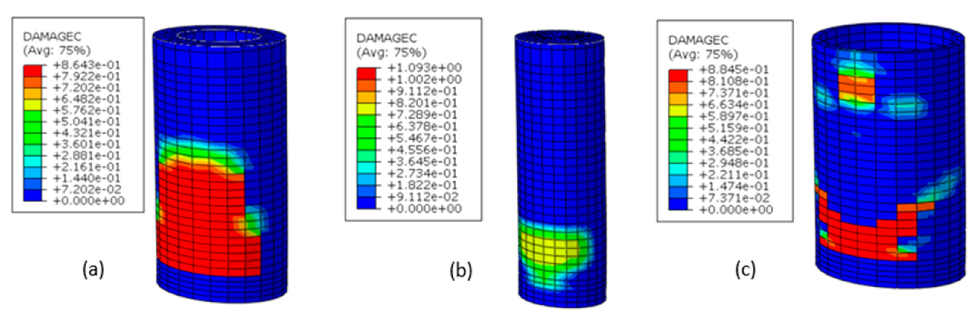
Figure 11.
Tension damage of (a) spun pile, (b) infill concrete and (c) concrete grouting .
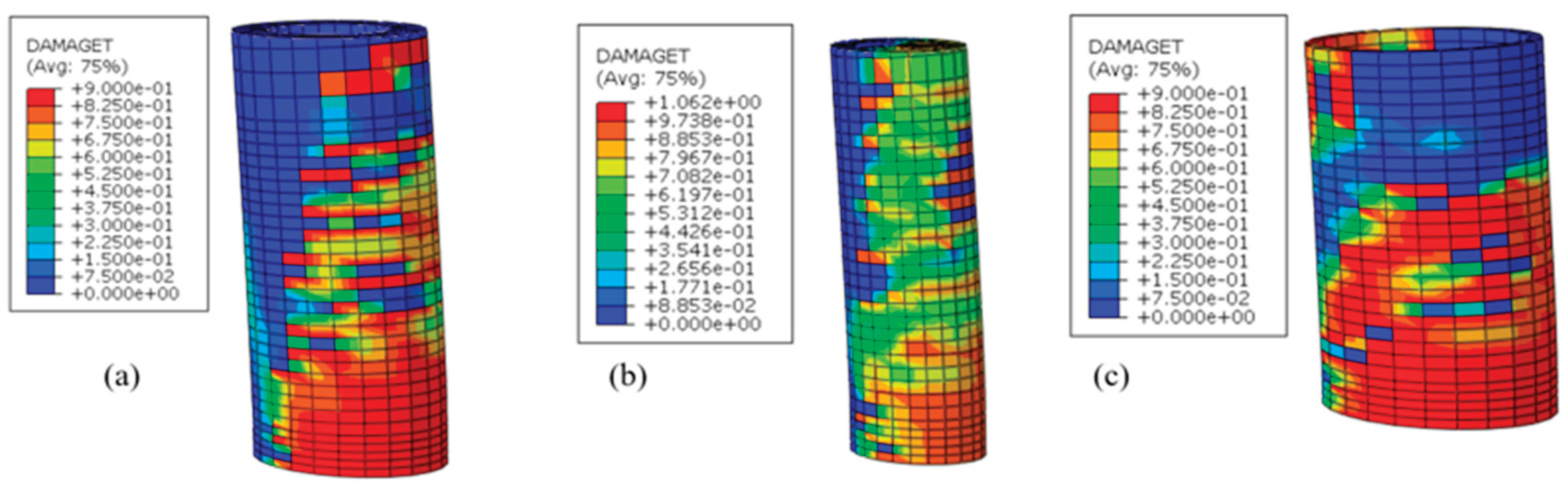
Figure 12.
Load-diplacement curve of different confinement ratio of the spun pile to pile without steel jacket
Figure 12.
Load-diplacement curve of different confinement ratio of the spun pile to pile without steel jacket
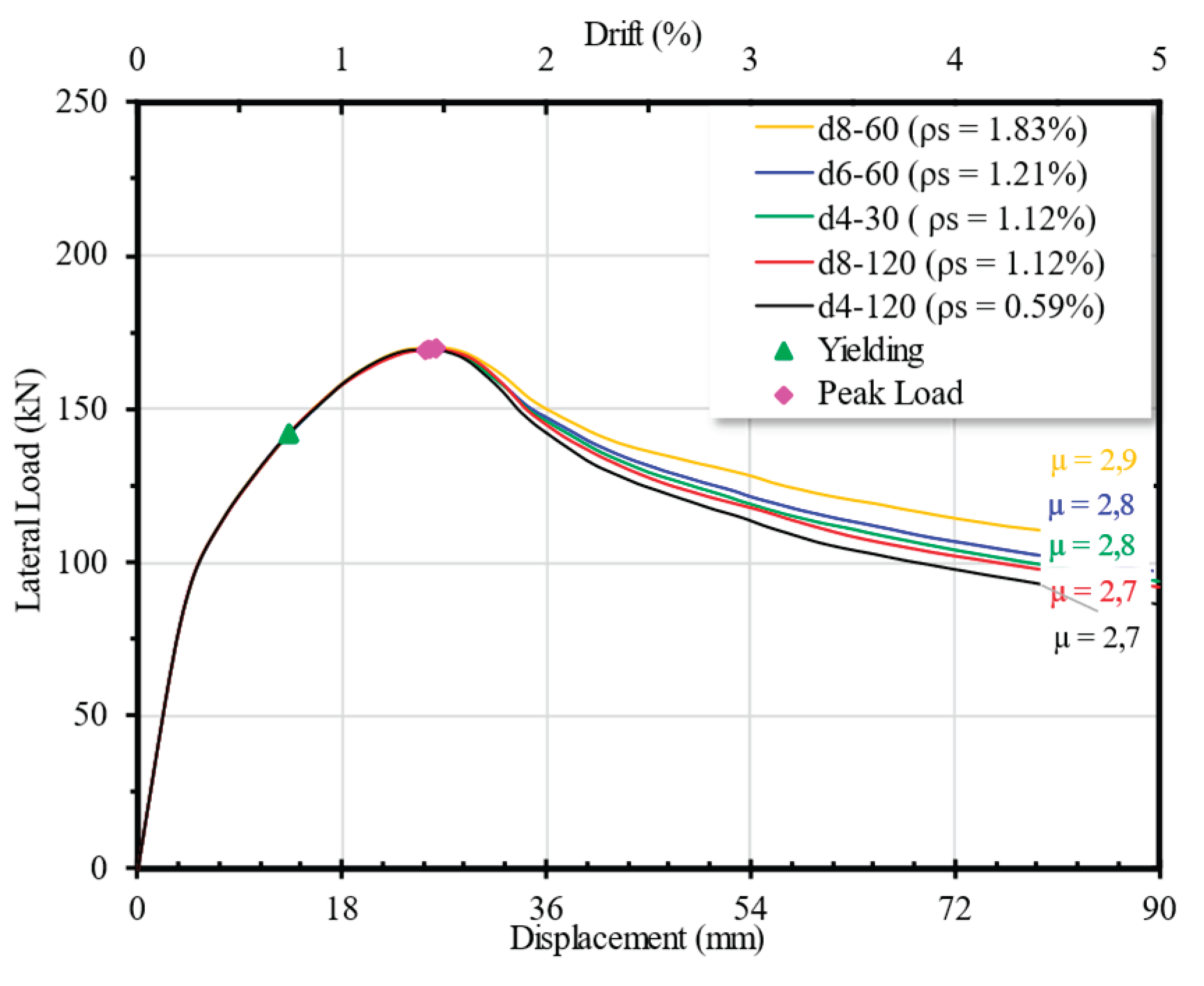
Figure 14.
The effect of bonding to (a) load-diplacement curve and (b) stress development of the bottom stirrup of the spun pile.
Figure 14.
The effect of bonding to (a) load-diplacement curve and (b) stress development of the bottom stirrup of the spun pile.
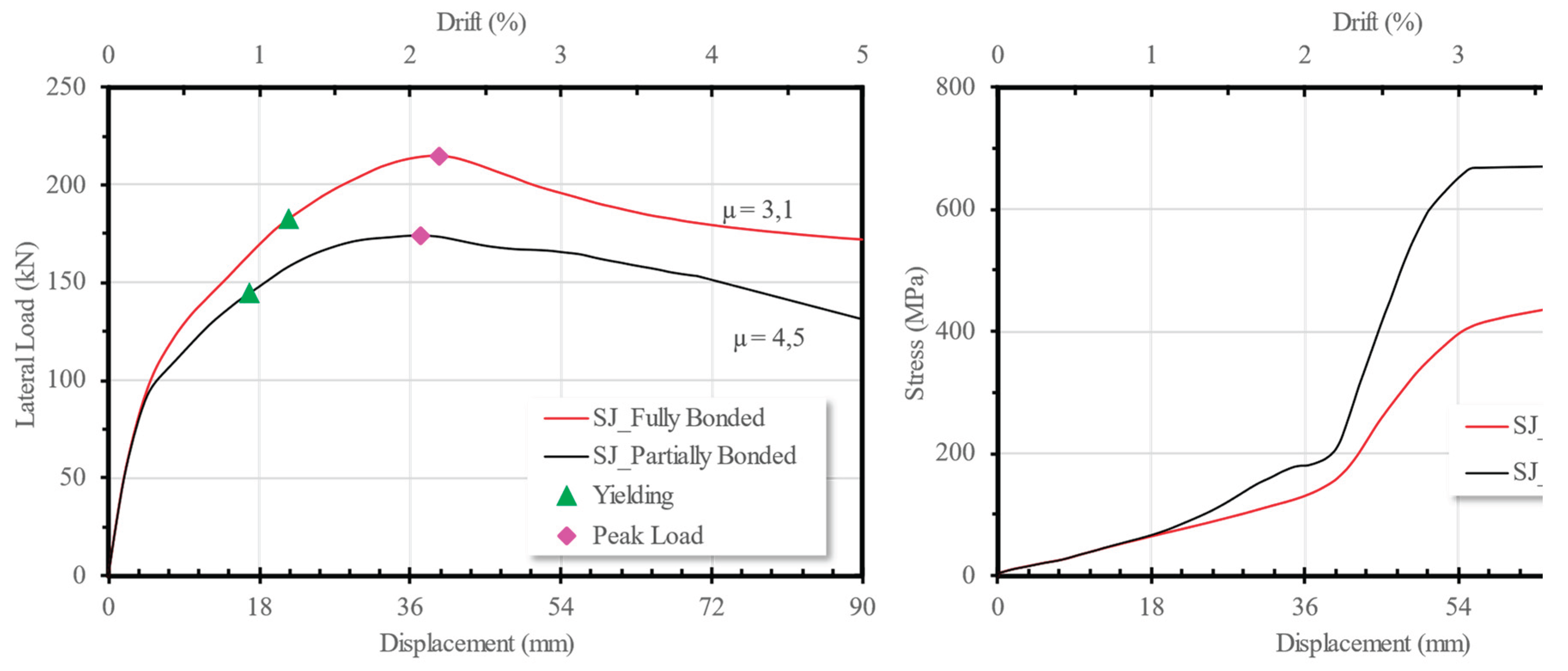
Figure 15.
Sress distribution on transverse reinforcement of speciment when the jacket (a) Partially and (b) Fully bonded .
Figure 15.
Sress distribution on transverse reinforcement of speciment when the jacket (a) Partially and (b) Fully bonded .
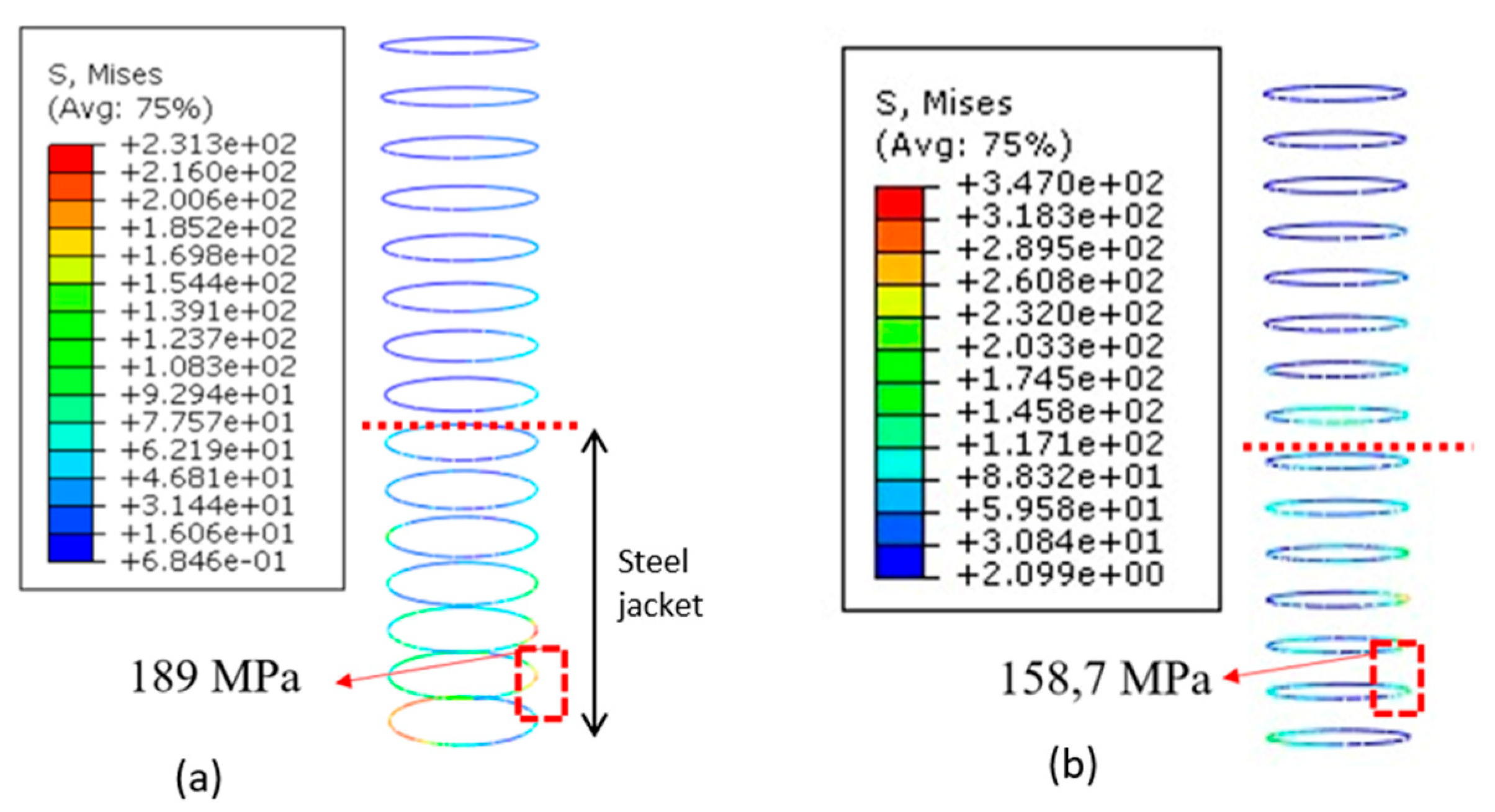
Figure 16.
The variation of thickness of steel jacket to (a) load-diplacement curve and (b) stress development of the bottom stirrup of the spun pile.
Figure 16.
The variation of thickness of steel jacket to (a) load-diplacement curve and (b) stress development of the bottom stirrup of the spun pile.
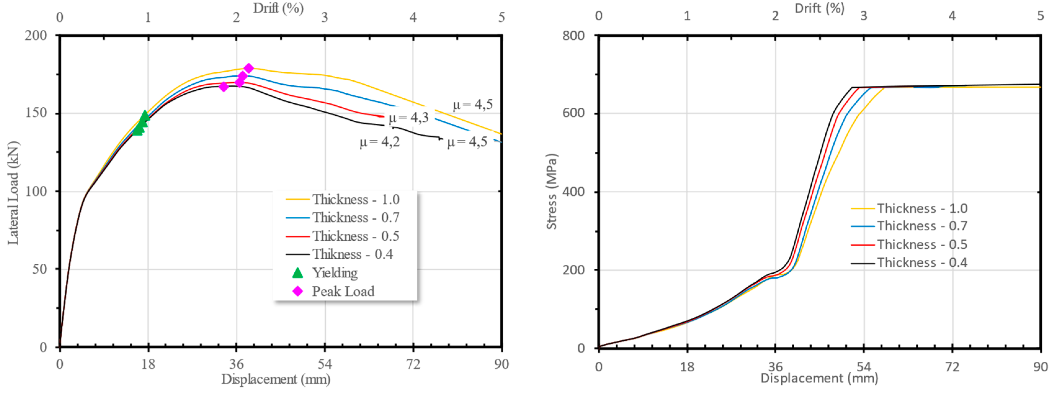
Figure 17.
The variation of height of steel jacket to (a) load-diplacement curve and (b) stress development of the bottom stirrup of the spun pile.
Figure 17.
The variation of height of steel jacket to (a) load-diplacement curve and (b) stress development of the bottom stirrup of the spun pile.
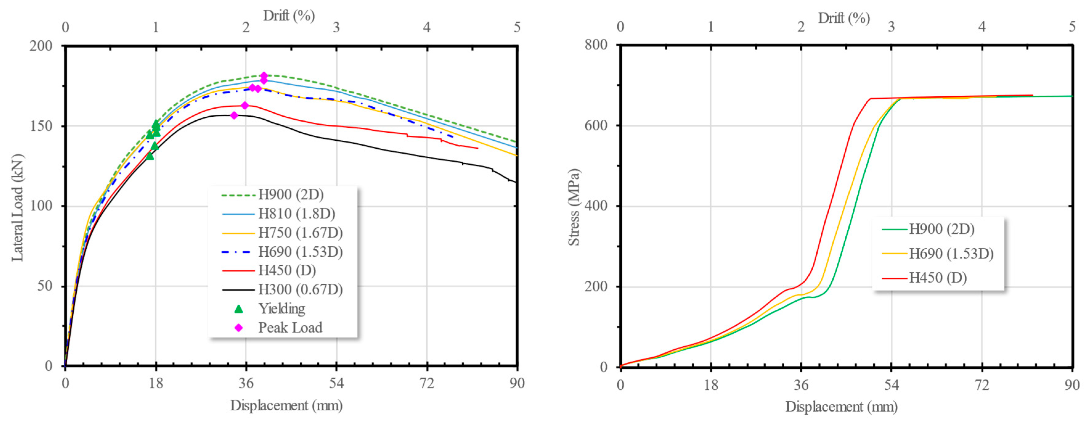
Figure 18.
The variation of axial load magnitude to (a) load-diplacement curve and (b) stress development of the bottom stirrup of the spun pile.
Figure 18.
The variation of axial load magnitude to (a) load-diplacement curve and (b) stress development of the bottom stirrup of the spun pile.
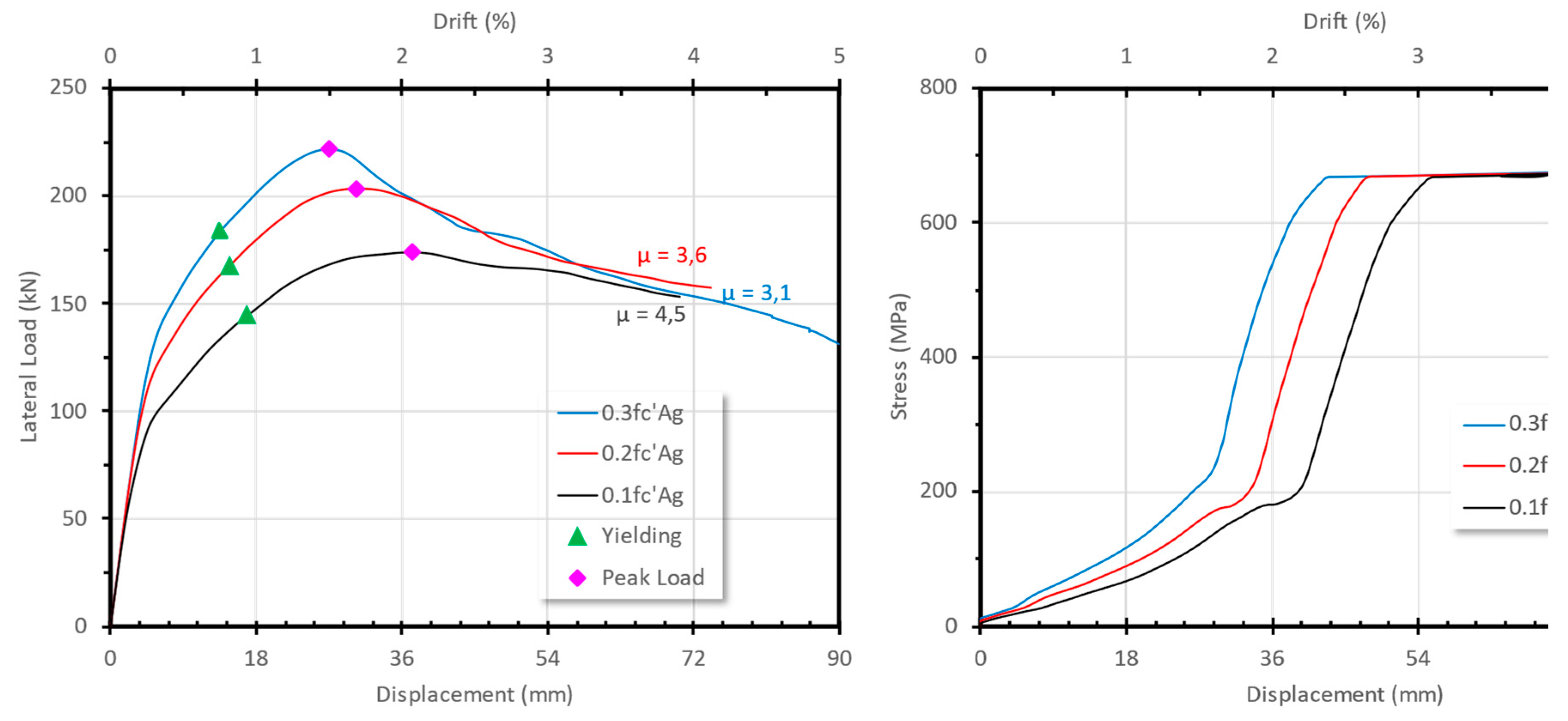

Table 1.
The Steel Strength.
| Location | fy (Mpa) | fu (Mpa) | Es (Mpa) |
|---|---|---|---|
| Prestress Bar | 1275 | 1562 | 2.0x10⁵ |
| Spiral of Pile | 570 | 703 | 2.0x10⁵ |
| D19 Rebar | 400 | 570 | 2.0x10⁵ |
| Spiral of Conc. infill | 240 | 370 | 2.0x10⁵ |
| Steel jacket | 519 | 529 | 2.0x10⁵ |
Disclaimer/Publisher’s Note: The statements, opinions and data contained in all publications are solely those of the individual author(s) and contributor(s) and not of MDPI and/or the editor(s). MDPI and/or the editor(s) disclaim responsibility for any injury to people or property resulting from any ideas, methods, instructions or products referred to in the content. |
© 2025 by the authors. Licensee MDPI, Basel, Switzerland. This article is an open access article distributed under the terms and conditions of the Creative Commons Attribution (CC BY) license (http://creativecommons.org/licenses/by/4.0/).
Copyright: This open access article is published under a Creative Commons CC BY 4.0 license, which permit the free download, distribution, and reuse, provided that the author and preprint are cited in any reuse.


