Submitted:
29 July 2025
Posted:
29 July 2025
You are already at the latest version
Abstract
All-solid-state lithium batteries (ASSLBs) employing Li-rich layered oxide (LLO) cathodes are regarded as promising next-generation energy storage systems owing to their outstanding energy density and intrinsic safety. Polymer-in-salt solid electrolytes (PISSE) offer advantages such as low processing costs, high ionic conductivity, and good anode compatibility; however, their practical deployment is hindered by poor oxidative stability especially under high-voltage. In this study, we report the rational design of a bilayer electrolyte architecture featuring an in situ solidified LiClO₄-doped succinonitrile (LiClO₄–SN) plastic-crystal interlayer between a Li₁.₂Mn₀.₆Ni₀.₂O₂ (LMNO) cathode and a PVDF-HFP-based PISSE. This PISSE/SN–LiClO₄ configuration exhibits a wide electrochemical stability window up to 4.7 V vs. Li+/Li and delivers a high ionic conductivity of 2.38 × 10⁻⁴ S cm-1 at 25 °C. The solidified LiClO₄-SN layer serves as an effective physical barrier, shielding the PVDF-HFP matrix from direct interfacial contact with LMNO and thereby suppressing its oxidative decomposition at elevated potentials. As a result, the bilayer polymer-based cells with LMNO cathode demonstrate an initial discharge capacity of ∼206 mAh g-1 at 0.05 C and exhibit good cycling stability with 85.7% capacity retention after 100 cycles at 0.5 C under a high cut-off voltage of 4.6 V. This work not only provides a promising strategy to enhance the compatibility of PVDF-HFP-based electrolytes with high-voltage cathodes through the facile in-situ solidification of plastic interlayers but also promotes the application of LMNO cathode material in high-energy ASSLBs.
Keywords:
Li-rich layered oxide
; PVDF-HFP
; polymer-in-salt electrolyte
; plastic interlayer
; all-solid-state batteries
1. Introduction
Given the escalating demand for high-energy-density applications, such as electric vehicles, unmanned aerial vehicles and grid-scale energy storage, there is an urgent imperative to further enhance the specific energy density, safety, and lifespan of Li-ion batteries [1]. However, state-of-the-art commercial cathode materials, including polyanion-structure (LiFePO4), layered-structure (LiCoO2, LiNixCoyMn1-x-yO2 and LiNi0.8Co0.15Al0.05O2) and spinel-structure (LiMn2O4), are approaching their theoretical performance limits (< 200 mAh g⁻¹). Li-rich Mn-based layered oxides (LRMOs) have emerged as promising cathodes due to their cost-effectiveness, significantly higher specific discharge capacities exceeding 250 mAh g⁻¹, and elevated operating voltages enabled by a synergistic cationic–anionic redox mechanism [2]. Coupling LRMOs with Li metal anodes further enhances the energy density of the resulting full cells. Despite these merits, practical deployment is hindered by poor cycling life and safety concerns. High-voltage activation of anionic redox processes often induces electrolyte decomposition and lattice oxygen release, which in turn cause interfacial degradation, including cathode–electrolyte interface (CEI) instability and transition metal dissolution [3,4]. Moreover, uncontrolled lithium dendrite growth during repeated stripping/plating cycles can pierce separators, leading to internal short circuits. These interfacial and structural instabilities, together with the flammability and leakage risks of liquid electrolytes, severely compromise battery longevity, voltage stability, and safety [5,6].
Solid-state electrolyte (SSE) engineering is widely recognized as one of the most promising strategies to effectively address or mitigate the above challenges [7]. State-of-the-art studies of solid-state LRMO|Li batteries reveal that solid electrolytes effectively expand the voltage stability window, mitigate oxygen release, and suppress transition metal leaching [8,9,10,11,12]. However, most of these studies have relied on sulfide or halide-based SSEs, which still face severe interfacial challenges at both the cathode and anode. Specifically, the high reactivity of Li-rich cathodes can trigger decomposition of sulfide or halide electrolytes, leading to the formation of insulating derivatives such as Li₂SO₄, P–O species, and LiCl-rich interphases. These phases increase interfacial impedance and hinder Li⁺ transport, ultimately degrading cycling stability. On the anode side, sulfide electrolytes undergo reductive decomposition to form electronically conductive byproducts such as Li₂S and Li₃P, which promote continuous parasitic reactions and lithium dendrite formation [13,14,15]. Halide electrolytes, though relatively more stable, also experience interfacial degradation and typically require artificial buffer layers to suppress undesirable side reactions and maintain interfacial integrity. Furthermore, the inherent mechanical brittleness of inorganic SSEs limits their ability to accommodate volume changes during cycling, leading to delamination and rapid performance degradation.
To address these multifaceted interfacial challenges, polymer-based SSEs, with their intrinsic mechanical flexibility and favorable interfacial compatibility, may open a new venue for solid LRMO|Li battery design. Although several gel electrolytes have demonstrated encouraging results, very few pure polymer electrolytes (i.e., without liquid components) have shown satisfactory performance in high-voltage LRMO-based systems [16]. Achieving high ionic conductivity, a wide electrochemical stability window, and stable electrode interfaces under high-voltage operation for polymer all-solid-state lithium batteries (ASSLBs) remains a formidable challenge. Conventional single-component polymer electrolytes typically lack a sufficiently wide electrochemical window to simultaneously ensure compatibility with both high-voltage cathodes and lithium metal anodes. For instance, succinonitrile (SN) exhibit appealing properties, including high ionic conductivity (10-3 S cm-1 at RT), a broad electrochemical window (> 5 V vs. Li+/Li), and low cost—making it a promising electrolyte candidate for high-voltage ASSLBs. However, SN undergoes highly spontaneous chemical reaction with Li metal, leading to severe degradation of the electrolyte/electrode interface [17,18,19,20].
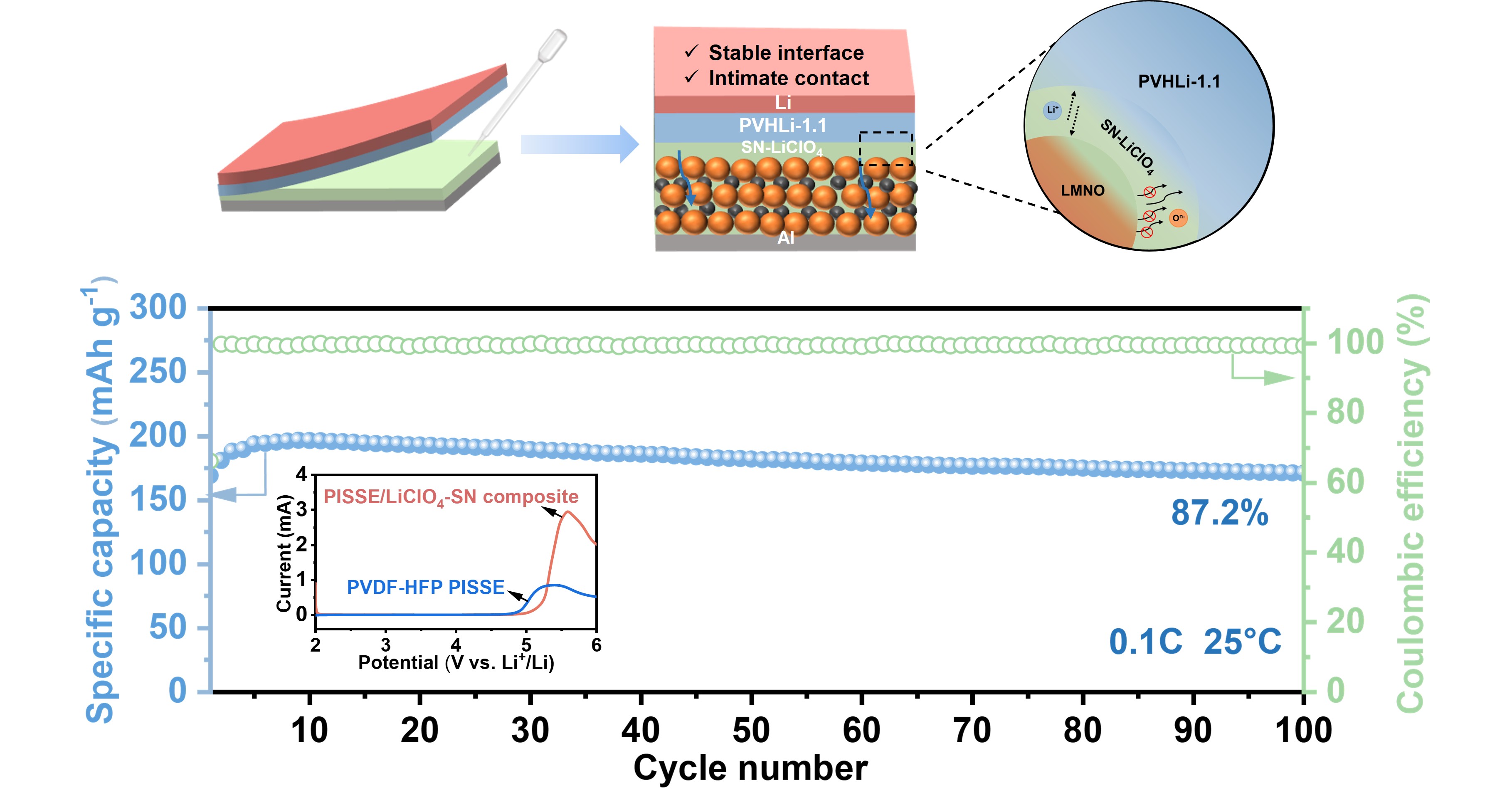
In this work, we construct a bilayer electrolyte architecture comprising a LiClO₄-doped succinonitrile (LiClO₄–SN) plastic-crystal interfacing the Li₁.₂Mn₀.₆Ni₀.₂O₂ (LMNO) cathode and a poly(vinylidene fluoride-co-hexafluoropropylene) (PVDF-HFP) based polymer-in-salt solid electrolytes (PISSE) contacting the Li anode. This design affords a broad electrochemical stability window up to 4.7 V and forms a stable multi-component interphase on the lithium surface. PISSEs have garnered attention due to their high room-temperature ionic conductivity, which can be tuned by simply increasing the salt concentration [21,22,23]. Previously, our group developed a PVDF-HFP based PISSE (PVHLi-1.1), which prepared by a facile solution-casting method by dissolving PVDF-HFP and LiTFSI at a mass of 1.1: 1 in N, N-dimethylformamide (DMF) [24]. The unique ionic clustering in PVHLi-1.1 enables the formation of a robust solid electrolyte interphase (SEI) on lithium, effectively suppressing dendrite growth and supporting stable cycling of LiNi0.5Co0.2Mn0.3O2 (LNMO) cathode under 4.3 V. However, to our best knowledge, the application of Li-rich cathodes in PISSE-based ASSLBs remains largely unexplored, primarily due to the limited oxidative stability of PVHLi-1.1 at voltages > 4.3 V. Achieving compatibility with high-voltage Li-rich cathodes while maintaining high energy density and interfacial stability remains a pressing challenge. By leveraging the advantages of SN-LiClO4 and PISSE, we developed a composite PVHLi-1.1/SN-LiClO4 polymer electrolyte that exhibits a wide stability window, high room-temperature ionic conductivity of 2.38 × 10⁻⁴ S cm-1, and a relative stable CEI interface. This bilayer system enables the successful operation of high-voltage LMNO in ASSLBs (Figure 1), delivering an initial discharge capacity of ∼206 mAh g-1 at 0.05 C and excellent cycling stability, retaining 85.7% capacity after 100 cycles at 0.5 C under a high cut-off voltage of 4.6 V.
2. Materials and Methods
2.1. Materials Preparation
2.2.1. Preparation of LMNO Cathode Material
LMNO was synthesized using the solid-state reaction method as previously reported [2]. Specifically, the precursors of Li2CO3, MnCO3, and Ni(OH)2 (Aladdin) with a stoichiometric ratio of Li : Ni : Mn = 1.2:0.2:0.6 were first thoroughly mixed using a planetary ball mill at 400 rpm for 12 h, followed by a pre-annealing process at a temperature of 450 °C for 3 h and a further calcination at 950 °C for 15 h in air.
2.2.2. Preparation of Composite Cathodes with SN-Based Modified Layers
To prepare the composite cathode, LMNO, conductive carbon black (Super P), and poly(vinylidene fluoride) (PVDF) were mixed in a mass ratio of 80:10:10 in N-methylpyrrolidone (NMP) solvent to form a homogeneous slurry. The slurry was uniformly cast onto aluminum foil and dried in a vacuum oven at 80 °C for over 24 hours to obtain the cathode film. For the modification layer, LiClO₄ and succinonitrile (SN) were mixed in a molar ratio of 1:20 and stirred at 80 °C until a transparent and flowable solution was formed. The resulted LiClO₄–SN solution was drop-cast onto the prepared LMNO cathode to ensure full infiltration into the porous electrode structure.
2.2.3. Preparation of PVHLi-1.1 Membranes
The PVHLi-1.1 electrolyte membranes were prepared via a conventional solution-casting method. Initially, PVDF-HFP (Mw = 400,000, Sigma-Aldrich) and LiTFSI (Suzhou DuoDuo Chemical Reagent Co., Ltd.) were dissolved in N,N-Dimethylformamide (DMF, Aladdin) at a weight ratio of 10:11:50. The mixture was then mechanically stirred for 5 h at 60 °C to obtain a homogeneous electrolyte slurry. Subsequently, the resulting viscous solution was cast onto a clean glass substrate using a doctor blade. Most of the DMF solvent was removed by air drying under ambient conditions with gentle electrical blowing. Finally, the membranes were further dried at 60 °C in a vacuum oven for 24 h to remove any residual solvent. The resulting PVDF-HFP electrolyte membrane, approximately 100 µm in thickness, was obtained by punching the formed film into circles with a diameter of 16 mm.
2.2. Materials Characterization
Powder X-ray diffraction (XRD) patterns of the LMNO samples were recorded using a Rigaku Ultima IV diffractometer with Cu Kα radiation (λ = 1.54178 Å) at room temperature. The surface morphology of the composite electrodes was characterized by field-emission scanning electron microscopy (SEM, TESCAN MIRA LMS), and the corresponding elemental distribution was analyzed using energy-dispersive X-ray spectroscopy (EDS) coupled with SEM. X-ray photoelectron spectroscopy (XPS, Thermo Scientific K-Alpha) equipped with a monochromatic Al Kα X-ray source was employed to examine the elemental chemical states. High-resolution transmission electron microscopy (HRTEM, Tecnai G2 F20, 200 kV) was used to investigate the microstructure of LMNO. Chemical bonding information was collected by Fourier-transform infrared spectroscopy (FTIR), and Raman spectra were acquired on an HR800 spectrometer using a 532 nm excitation laser. For XRD, DSC, FTIR, and Raman analyses, the LiClO₄–SN solid polymer electrolyte (SPE) samples were prepared by casting the LiClO₄–SN solution onto a soft substrate at 80 °C, followed by peeling prior to testing.
2.3. Electrochemical measurement
2.3.1. Ion Conductivity Testing
The ionic conductivities of the solid polymer electrolyte (SPE) were determined through the electrochemical impedance spectra (EIS) of the stainless-steel SS/SPE/SS blocking cell in the frequency range from 1 HZ to 106 Hz with an alternating current (AC) amplitude of 10 mV at various temperatures from 25 to 80°C. The ionic conductivity (σ) was calculated using the following equation,
where R (Ω) is the resistant value of the SPE obtained from the EIS curve, L (cm) denotes the thickness of SPE, and S (cm2) indicates the area of SPE. The activation energy was determined using the Arrhenius Equation,
where A is the pre-exponential factor, Ea signifies the activation energy of activated ion-hopping conduction process, and T denotes the absolute temperature.
2.3.2. Linear Sweep Voltammetry Testing
Linear sweep voltammetry (LSV) was performed to evaluate the electrochemical stability of the electrolyte, utilizing a scan rate of 1.0 mV s-1 over a voltage range from 2.0 to 6.0 V Li⁺/Li.
2.3.3. Battery Performance Evaluation
All assembled ASSLBs were cycled between 2.0 and 4.6 V vs. Li⁺/Li using a LAND CT2001A battery tester at 25 °C. Charge–discharge stability was assessed under ambient conditions. To further evaluate the rate capability, galvanostatic cycling was conducted at various current rates ranging from 0.05 C to 0.5 C.
3. Results and discussion
3.1. Characterization of LMNO Cathode
The crystal structure of LMNO was determined by X-ray diffraction (XRD) followed by Rietveld refinement. As shown in Figure 2a, all diffraction peaks can be well indexed to the monoclinic phase with the C2/m space group, which also generates several superlattice reflections between 20° and 25°. The refinement parameters are summarized in Table 1. The SEM image (Figure 2b) reveals that the LMNO particles are uniformly distributed, with slight agglomeration, smooth surfaces, and an average size of approximately 250 nm. Further insight into the morphology and crystal structure was provided by high-resolution transmission electron microscopy (HRTEM), as shown in Figure 2c and 2d. The lattice spacing of 0.472 nm, determined via fast Fourier transform (FFT), corresponds well to the (003) planes of the C2/m layered structure. Elemental mapping by SEM-EDX (Figure 2e–g) confirms the uniform distribution of O, Mn, and Ni within the LMNO particles.
3.2. Characterizations of SN-LiClO4
Figure S1 presents the morphology and intrinsic electrochemical properties of PVHLi-1.1. LiTFSI is uniformly distributed within the PVDF-HFP matrix, enabling a high Li⁺ transport number of 0.51, and high compatibility with Li anode. However, although the PVHLi-1.1 electrolyte exhibits a broader electrochemical stability window compared to normal liquid electrolyte (1 M LiPF6 in EC/DEC) and standard SPEs [24], it remains insufficient to meet the charging demands of the high-voltage LMNO cathode. Figure S2 shows the charge/discharge curve when PVHLi-1.1 is used alone as the SPE, indicating electrolyte decomposition during charging.
To address this, we constructed an in-situ cured SN plastic crystal layer doped with LiClO₄ between the PVHLi-1.1 electrolyte and the LMNO cathode, leveraging the high oxidative stability of SN and the high conductivity of LiClO₄. When SN plastic crystal was mixed with a definded amount of LiClO4, the resulting blend formed a uniform, flowable, and transparent liquid at 80 °C. As shown in Figure 3a, the mixture remained liquid at 80 °C but solidified upon cooling to room temperature. Notably, in both high-temperature (liquid) and low-temperature (solid) states, the ionic conductivity exhibited temperature dependence that followed Arrhenius behavior. The Arrhenius plot of SN–LiClO₄ from 25 to 90 °C (Figure 3d) revealed two distinct regions corresponding to the plastic crystalline and molten states [25]. DSC (Figure 3e) also confirmed the phase transition of SN–LiClO₄ from a plastic crystalline to a molten state between 30 and 80 °C. The XRD pattern (Figure 3f) of the SN–LiClO₄ mixture was nearly identical to that of pure SN, indicating complete salt dissociation without disrupting the SN lattice. Additionally, Figure 3h displayed the magnified FTIR spectra of pure SN and the mixture of SN and LiClO4. The appearance of a characteristic peak at 2281 cm-1 indicates SN solvation and strong SN–Li⁺ interactions [26,27]. Peaks at 762, 819, 1002, and 1425 cm-1 are attributed to CH2 group, while the 2254 cm-1 peak corresponds to the C≡N group, consistent with prior reports (Figure 3g) [28]. Raman spectroscopy further confirmed the complete dissolution of LiClO₄ in the SN matrix (Figure 3h).
The calculated activation energies of PVHLi-1.1/SN–LiClO₄ composite were 0.34 eV (low-temperature region) and 0.16 eV (high-temperature region). Notably, the composite exhibited a high room-temperature ionic conductivity of 2.38 × 10⁻⁴ S cm⁻¹, nearly double that of PVHLi-1.1 alone (Figure 3b). More importantly, its electrochemical stability window, determined by LSV (Figure 3c), was significantly extended compared to pure PVHLi-1.1. The oxidation onset of PVHLi-1.1 occurs around 4.3 V, intensifying above 4.5 V, thus rendering it incompatible with high-voltage Li-rich cathodes. In contrast, the PVHLi-1.1/SN–LiClO₄ electrolyte, benefitting from the oxidative stability of SN’s terminal nitrile groups [29,30], exhibited an expanded potential window up to 4.7 V, making it more compatible with LMNO cathodes.
3.3. High-Voltage LNMO|PVHLi-1.1-SN–LiClO₄|Li ASSLB Performance Test
In order to further reduce the interfacial resistance and reduce the side reaction between SN and lithium anode, the SN-LiClO4 solution was first injected into the porous cathode to form an integrated composite electrode (S-LMNO), and then assembled with PVHLi-1.1 to construct a high-voltage battery to evaluate the electrochemical performance of the intermediate layer (Figure 4a). Figure 4b displayed the rate performance of the S-LMNO/PVHLi-1.1/Li cell from 0.05 C to 0.5 C. At a charge cutoff voltage of 4.6 V, the battery delivered discharge specific capacities of approximately 206.3, 195.4, 147.1, and 115.1 mAh g-1 at rates of 0.05 C, 0.1 C, 0.2 C, and 0.5 C, respectively. When the current was changed back to 0.05 C, the discharge capacity recovered to 204.5 mAh g-1. The good rate performance indicates that the SN intermediate layer possesses good electrical conductivity as well as high oxidation resistance. In terms of cycling performance, after 100 cycles at 0.1, 0.2, and 0.5 C rates, all batteries exhibited capacity retention rates exceeding 84% at 25 °C, achieving excellent cycling stability (Figure 4c–h). Like other reported Li, Mn-rich layered oxides, all cells exhibited a long plateau at ~4.55 V in the high-voltage region, often referred to as the electrochemical activation process. The discharge capacity was close to 200.0 mAh g-1 at 0.1 C, which although is slightly lower than the PVDF-HFP based gel electrolyte [31], but represents a breakthrough for Li-rich manganese-based cathodes in polymer-based ASSLBs. This could be attributed to the good interfacial compatibility and excellent Li+ transfer between the high-voltage LMNO cathode and the PVHLi-1.1-based electrolyte. Additionally, for all batteries tested at different rates, the corresponding high coulombic efficiency remained above 99%, indicating that the SN-LiClO4 elastomeric interlayer suppressed the decomposition of PVHLi-1.1 at high charging potentials.
Meanwhile, we have also assembled S-LMNO|PVHLi-1.1|Li pouch cells to verify their practical applicability (Figure 5a). By increasing the cathode mass loading, we achieved a breakthrough in energy density. With an LMNO loading of 4.25 mg/cm2, a discharge capacity of 0.72 mAh/cm2 was successfully achieved. The capacity retention was 80.5% even after 40 cycles at a current density of 0.5 C (Figure 5b). As shown in Figure 5(c-e), the open-circuit voltage of the assembled ASSLBs did not exhibit a significant decrease during the folding and cutting tests. Figure 5(f–h) depicts the abuse experiments on the pouch cell, where it was observed that the cell continued to illuminate a high-intensity LED bulb, even after being subjected to folding and cutting damage. Notably, there were no indications of internal short circuits or combustion, and the brightness of the LED remained virtually unchanged, underscoring the battery's exceptional safety performance. These tests confirm that the S-LMNO/PVHLi-1.1/Li battery holds promising potential for practical applications.
3.4. Interface Analysis
To gain deeper insights into the role of the SN–LiClO₄ interlayer in regulating cathode–electrolyte interphase (CEI) formation in the LMNO|PVHLi-1.1|Li cell, detailed ex situ XPS measurements were conducted to collect O 1s spectra from P-LMNO (without the SN–LiClO₄ interlayer) and S-LMNO composite cathodes at both the fully charged (C-4.6 V) and fully discharged (D-2.0 V) states after the first cycle.
As shown in Figure 6a,d, for the P-LMNO electrode charged to 4.6 V and discharged to 2.0 V, two dominant O 1s peaks were identified at 532.8 eV (purple) and 531.8 eV (blue), corresponding to surface oxygenated species such as C–O/C=O and LiOH/Li₂CO₃, respectively [24,28,32]. These species are attributed to CEI formation and intensive parasitic reactions, including the decomposition of TFSI⁻ anions during cycling. Notably, the O 1s signal corresponding to the lattice oxygen (O²⁻, green) in LMNO was absent, likely due to the extensive coverage by decomposition products on the electrode surface. After Ar⁺ sputtering to a depth of ~20 nm, weak lattice oxygen signals emerged in both electrodes. Additionally, a minor peak at ~530.5 eV (red) appeared in the charged P-LMNO sample (D-2.0 V), which is assigned to low electron density oxygen species (O₂ⁿ⁻), indicative of surface-localized anionic redox activity or oxidative oxygen intermediates [28,33].
In contrast, the S-LMNO electrode at both the charged and discharged states (Figure 6b,e) exhibited markedly fewer organic byproducts, indicating suppressed electrolyte decomposition. Moreover, more pronounced signals corresponding to lattice oxygen (O²⁻, ~529.6 eV) and low-electron-density oxygen species (O₂ⁿ⁻) were observed, suggesting improved lattice oxygen stability and enhanced participation of anionic redox processes. Notably, the binding energy of O₂ⁿ⁻ on the surface shifted to a higher value (~531.0 eV), which likely reflects an evolution of the oxygen electronic structure—from a delocalized high-valence state near the surface to a more localized configuration within the bulk lattice [34,35]. Upon discharging to 2.0 V, the surface O₂ⁿ⁻ signal in S-LMNO decreased significantly, further confirming that the introduction of the SN–LiClO₄ plastic crystal interlayer effectively mitigates interfacial parasitic reactions and promotes the reversibility of the oxygen redox process.
4. Conclusions
In summary, to enable high-voltage all-solid-state Li-rich manganese-based oxide (LRMO)|Li batteries, a bilayer polymer electrolyte was constructed by in situ introducing a SN–LiClO₄ interlayer between PVHLi-1.1 PISSE and the high-voltage cathode. This strategy effectively expanded the electrochemical stability window to 4.7 V and enhanced the room-temperature ionic conductivity to 2.38 × 10⁻⁴ S cm⁻¹. As a result, the assembled solid-state battery delivered a high initial capacity of 206 mAh g⁻¹ within 2.4–4.6 V, and exhibit an outstanding cycling stability with 85.7% capacity retention after 100 cycles at 0.5 C under a high cut-off voltage of 4.6 V. The solidified SN layer further acted as a robust physical barrier, mitigating the oxidative decomposition of PVDF-HFP induced by the highly reactive LRMO cathode. XPS analysis confirmed that the in situ formed SN–LiClO₄ layer effectively suppressed interfacial side reactions and enhanced the reversibility of anionic (oxygen) redox processes. The assembled solid-state cell also exhibited excellent mechanical integrity and safety performance under external mechanical stress. This work provides a promising strategy to advance the practical application of high-energy Li-rich cathodes in all-solid-state lithium batteries.
Supplementary Materials
The following supporting information can be downloaded at the website of this paper posted on Preprints.org, Figure S1: Morphology and intrinsic electrochemical properties of PVHLi-1.1 electrolyte; Figure S2: Charge-discharge curves of solid LNMO|Li cell using PVHLi-1.1 PSE without LiClO4-SN interlayer at 0.1 C.
Author Contributions
Conceptualization, M.S.; methodology, Z.F., F.W.; formal analysis, Z.F. and J.T.; writing—original draft preparation, Z.F. and J.T.; writing and supervision—review and editing, M.S. All authors have read and agreed to the published version of the manuscript.
Funding
This research was funded by the National Natural Science Foundation of China (22309142).
Data Availability Statement
The original contributions presented in the study are included in the article, further inquiries can be directed to the corresponding author.
Acknowledgments
We would like to thank Jinping Liu and Liang Xiao (Wuhan University of technologies) for the fruitful discussions.
Conflicts of Interest
The authors declare no conflicts of interest.
References
- Du, H.; Zhang, X.; Yu, H. Design of high-energy-density lithium batteries: Liquid to all solid state. eTransportation 2024, 23. [CrossRef]
- Xu, J.; Sun, M.; Qiao, R.; Renfrew, S.E.; Ma, L.; Wu, T.; Hwang, S.; Nordlund, D.; Su, D.; Amine, K.; et al. Elucidating anionic oxygen activity in lithium-rich layered oxides. Nat. Commun. 2018, 9, 1–10. [CrossRef]
- Wang, H.; Geng, X.; Hu, L.; Wang, J.; Xu, Y.; Zhu, Y.; Liu, Z.; Lu, J.; Lin, Y.; He, X. Efficient direct repairing of lithium- and manganese-rich cathodes by concentrated solar radiation. Nat. Commun. 2024, 15, 1–13. [CrossRef]
- Yuan, X.; Dong, T.; Liu, J.; Cui, Y.; Dong, H.; Yuan, D.; Zhang, H. Bi-affinity Electrolyte Optimizing High-Voltage Lithium-Rich Manganese Oxide Battery via Interface Modulation Strategy. Angew. Chem. Int. Ed. Engl. 2023, 62, e202304121. [CrossRef]
- Liu, W.; Li, J.; Li, W.; Xu, H.; Zhang, C.; Qiu, X. Inhibition of transition metals dissolution in cobalt-free cathode with ultrathin robust interphase in concentrated electrolyte. Nat. Commun. 2020, 11, 1–11. [CrossRef]
- Betz, J.; Brinkmann, J.; Nölle, R.; Lürenbaum, C.; Kolek, M.; Stan, M.C.; Winter, M.; Placke, T. Cross Talk between Transition Metal Cathode and Li Metal Anode: Unraveling Its Influence on the Deposition/Dissolution Behavior and Morphology of Lithium. Adv. Energy Mater. 2019, 9. [CrossRef]
- Antony Jose, S.; Gallant, A.; Gomez, P. L.; Jaggers, Z.; Johansson, E.; LaPierre, Z.; Menezes, P. L. Solid-State Lithium Batteries: Advances, Challenges, and Future Perspectives. Batteries, 2025, 11, 90. [CrossRef]
- Hu, N.; Zhang, Y.; Yang, Y.; Wu, H.; Liu, Y.; Hao, C.; Zheng, Y.; Sun, D.; Li, W.; Li, J.; et al. Unraveling the Spatial Asynchronous Activation Mechanism of Oxygen Redox-Involved Cathode for High-Voltage Solid-State Batteries. Adv. Energy Mater. 2024, 14. [CrossRef]
- Yu, R.; Wang, C.; Duan, H.; Jiang, M.; Zhang, A.; Fraser, A.; Zuo, J.; Wu, Y.; Sun, Y.; Zhao, Y.; Liang, J.; Fu, J.; Deng, S.; Ren, Z.; Li, G.; Huang, H.; Li, R.; Chen, N.; Wang, J.; Li, X.; Singh, C. V.; Sun, X. Manipulating Charge-Transfer Kinetics of Lithium-Rich Layered Oxide Cathodes in Halide All-Solid-State Batteries. Adv. Mater. 2023, 35, 2207234. [CrossRef]
- Wu, Y.; Zhou, K.; Ren, F.; Ha, Y.; Liang, Z.; Zheng, X.; Wang, Z.; Yang, W.; Zhang, M.; Luo, M.; Battaglia, C.; Yang, W.; Zhu, L.; Gong, Z.; Yang, Y. Highly Reversible Li2RuO3 Cathodes in Sulfide-based All Solid-state Lithium Batteries. Energy Environ. Sci. 2022, 15, 3470-3482.
- Sun, S.; Zhao, C.-Z.; Yuan, H.; Fu, Z.-H.; Chen, X.; Lu, Y.; Li, Y.-F.; Hu, J.-K.; Dong, J.; Huang, J.-Q.; et al. Eliminating interfacial O-involving degradation in Li-rich Mn-based cathodes for all-solid-state lithium batteries. Sci. Adv. 2022, 8, eadd5189. [CrossRef]
- Liu, B.; Hu, N.; Li, C.; Ma, J.; Zhang, J.; Yang, Y.; Sun, D.; Yin, B.; Cui, G. Direct Observation of Li-Ion Transport Heterogeneity Induced by Nanoscale Phase Separation in Li-rich Cathodes of Solid-State Batteries. Angew. Chem. Int. Ed. 2022, 61, e202209626. [CrossRef]
- Cao, C.; Carbone, M.R.; Komurcuoglu, C.; Shekhawat, J.S.; Sun, K.; Guo, H.; Liu, S.; Chen, K.; Bak, S.-M.; Du, Y.; et al. Atomic insights into the oxidative degradation mechanisms of sulfide solid electrolytes. Cell Rep. Phys. Sci. 2024, 5. [CrossRef]
- Li, J.; Luo, J.; Li, X.; Fu, Y.; Zhu, J.; Zhuang, X. Li Metal Anode Interface in Sulfide-based All-solid-state Li batteries. EcoMat 2023, 5, e12383. [CrossRef]
- Byeon, Y.-W.; Kim, H. Review on Interface and Interphase Issues in Sulfide Solid-State Electrolytes for All-Solid-State Li-Metal Batteries. Electrochem 2021, 2, 452–471. [CrossRef]
- Wang, H.; Yang, Y.; Gao, C.; Chen, T.; Song, J.; Zuo, Y.; Fang, Q.; Yang, T.; Xiao, W.; Zhang, K.; et al. An entanglement association polymer electrolyte for Li-metal batteries. Nat. Commun. 2024, 15, 1–12. [CrossRef]
- Chen, S.; Wang, S.; Peng, Q.; Wei, Z.; Cheng, S.; Fang, Z.; Duan, P.; Cheng, Y.; Cheng, Y.; Jin, K.; et al. In-situ fabricated succinonitrile-based composite electrolyte for high-performance and safe solid-state lithium batteries. J. Power Sources 2024, 604. [CrossRef]
- Chen, J.; Yang, Z.; Xu, X.; Qiao, Y.; Zhou, Z.; Hao, Z.; Chen, X.; Liu, Y.; Wu, X.; Zhou, X.; et al. Nonflammable Succinonitrile-Based Deep Eutectic Electrolyte for Intrinsically Safe High-Voltage Sodium-Ion Batteries. Adv. Mater. 2024, 36, e2400169. [CrossRef]
- Bao, D.; Tao, Y.; Zhong, Y.; Zhao, W.; Peng, M.; Zhang, H.; Sun, X. High-Performance Dual-Salt Plastic Crystal Electrolyte Enabled by Succinonitrile-Regulated Porous Polymer Host. Adv. Funct. Mater. 2023, 33, 2213211. [CrossRef]
- Das, S.; Prathapa, S.J.; Menezes, P.V.; Row, T.N.G.; Bhattacharyya, A.J. Study of Ion Transport in Lithium Perchlorate-Succinonitrile Plastic Crystalline Electrolyte via Ionic Conductivity and in Situ Cryo-Crystallography. J. Phys. Chem. B 2009, 113, 5025–5031. [CrossRef]
- Li, Y.; Yuan, W.; Hu, Z.; Shen, Y.; Wu, G.; Cong, F.; Fu, X.; Lu, F.; Li, Y.; Liu, P.; et al. Constructing PVDF-Based Polymer Electrolyte for Lithium Metal Batteries by Polymer-Induced Phase Structure Adjustment Strategy. Adv. Funct. Mater. 2025, 35. [CrossRef]
- Xiong, Z.; Wang, Z.; Zhou, W.; Liu, Q.; Wu, J.-F.; Liu, T.-H.; Xu, C.; Liu, J. 4.2V polymer all-solid-state lithium batteries enabled by high-concentration PEO solid electrolytes. Energy Storage Mater. 2023, 57, 171–179. [CrossRef]
- Li, H.; Du, Y.; Wu, X.; Xie, J.; Lian, F. Developing “Polymer-in-Salt” High Voltage Electrolyte Based on Composite Lithium Salts for Solid-State Li Metal Batteries. Adv. Funct. Mater. 2021, 31, 2103049. [CrossRef]
- Liu, W.; Yi, C.; Li, L.; Liu, S.; Gui, Q.; Ba, D.; Li, Y.; Peng, D.; Liu, J. Designing Polymer-in-Salt Electrolyte and Fully Infiltrated 3D Electrode for Integrated Solid-State Lithium Batteries. Angew. Chem. Int. Ed. Engl. 2021, 60, 12931–12940. [CrossRef]
- Liu, Q.; Yu, Q.; Li, S.; Wang, S.; Zhang, L.; Cai, B.; Zhou, D.; Li, B. Safe LAGP-based all solid-state Li metal batteries with plastic super-conductive interlayer enabled by in-situ solidification. Energy Storage Mater. 2020, 25, 613–620. [CrossRef]
- Hu, Z.; Xian, F.; Guo, Z.; Lu, C.; Du, X.; Cheng, X.; Zhang, S.; Dong, S.; Cui, G.; Chen, L. Nonflammable Nitrile Deep Eutectic Electrolyte Enables High-Voltage Lithium Metal Batteries. Chem. Mater. 2020, 32, 3405–3413. [CrossRef]
- Wang, Q.; Fan, H.; Fan, L.-Z.; Shi, Q. Preparation and performance of a non-ionic plastic crystal electrolyte with the addition of polymer for lithium ion batteries. Electrochimica Acta 2013, 114, 720–725. [CrossRef]
- Shen, C.; Liu, Y.; Hu, L.; Li, W.; Liu, X.; Shi, Y.; Jiang, Y.; Zhao, B.; Zhang, J. Regulating anionic redox activity of lithium-rich layered oxides via LiNbO3 integrated modification. Nano Energy 2022, 101. [CrossRef]
- Zhao, B.; Yang, M.; Li, J.; Li, S.; Zhang, G.; Liu, S.; Cui, Y.; Liu, H. Cellulose-Based Plastic Crystal Electrolyte Membranes with Enhanced Interface for Solid-State Lithium Batteries. Energy Technol. 2021, 9, 2100114. [CrossRef]
- Arunkumar, R.; Babu, R.S.; Rani, M.U.; Kalainathan, S. Effect of PBMA on PVC-based polymer blend electrolytes. J. Appl. Polym. Sci. 2017, 134. [CrossRef]
- Bian, X.; Liang, J.; Tang, X.; Li, R.; Kang, L.; Su, A.; Su, X.; Wei, Y. A boron nitride-polyvinylidene fluoride-co-hexafluoropropylene composite gel polymer electrolyte for lithium metal batteries. J. Alloy. Compd. 2019, 803, 1075–1081. [CrossRef]
- Zhang, L.; Xu, X.; Jiang, S.; Wei, L.; Xi, K.; Lei, Y.; Cheng, X.; Yin, J.; Gao, Y. Halloysite nanotubes modified poly(vinylidenefluoride-co-hexafluoropropylene)-based polymer-in-salt electrolyte to achieve high-performance Li metal batteries. J. Colloid Interface Sci. 2023, 645, 45–54. [CrossRef]
- Sathiya, M.; Rousse, G.; Ramesha, K.; Laisa, C.P.; Vezin, H.; Sougrati, M.T.; Doublet, M.-L.; Foix, D.; Gonbeau, D.; Walker, W.; et al. Reversible anionic redox chemistry in high-capacity layered-oxide electrodes. Nat. Mater. 2013, 12, 827–835. [CrossRef]
- Naylor, A.J.; Makkos, E.; Maibach, J.; Guerrini, N.; Sobkowiak, A.; Björklund, E.; Lozano, J.G.; Menon, A.S.; Younesi, R.; Roberts, M.R.; et al. Depth-dependent oxygen redox activity in lithium-rich layered oxide cathodes. J. Mater. Chem. A 2019, 7, 25355–25368. [CrossRef]
- Shimoda, K.; Minato, T.; Nakanishi, K.; Komatsu, H.; Matsunaga, T.; Tanida, H.; Arai, H.; Ukyo, Y.; Uchimoto, Y.; Ogumi, Z. Oxidation behaviour of lattice oxygen in Li-rich manganese-based layered oxide studied by hard X-ray photoelectron spectroscopy. J. Mater. Chem. A 2016, 4, 5909–5916. [CrossRef]
Figure 1.
Schematic illustration of the ASSLBs consisting of LMNO electrode and PVHLi-1.1 electrolyte, showing the interface modification with the introduction of the SN-LiClO4 layer improves the interface and cathode particle contact.
Figure 1.
Schematic illustration of the ASSLBs consisting of LMNO electrode and PVHLi-1.1 electrolyte, showing the interface modification with the introduction of the SN-LiClO4 layer improves the interface and cathode particle contact.
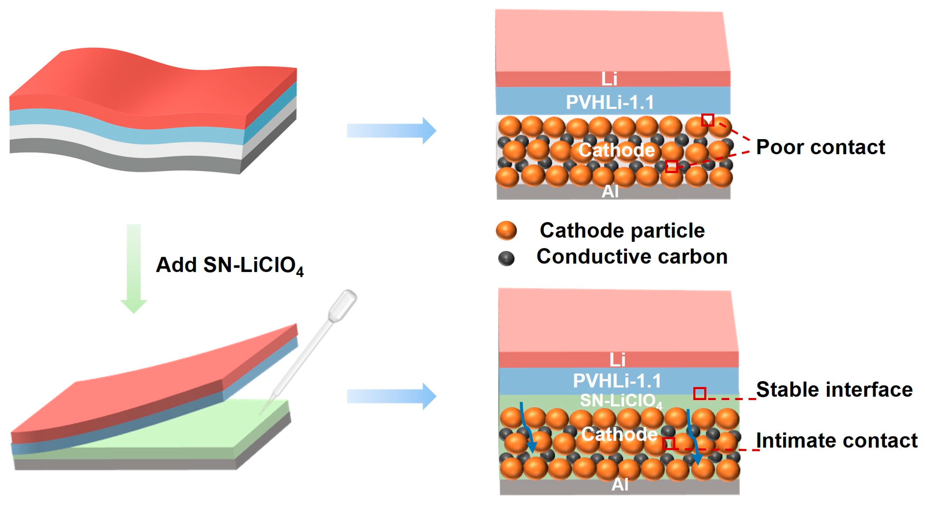
Figure 2.
(a) XRD Rietveld refinement of LMNO sample; (b) SEM images of LMNO sample; (c-d) HRTEM images of LMNO sample and corresponding Fast Fourier Transform (FFT); (e-g) EDS mapping (O, Mn, and Ni) images of LMNO sample.
Figure 2.
(a) XRD Rietveld refinement of LMNO sample; (b) SEM images of LMNO sample; (c-d) HRTEM images of LMNO sample and corresponding Fast Fourier Transform (FFT); (e-g) EDS mapping (O, Mn, and Ni) images of LMNO sample.
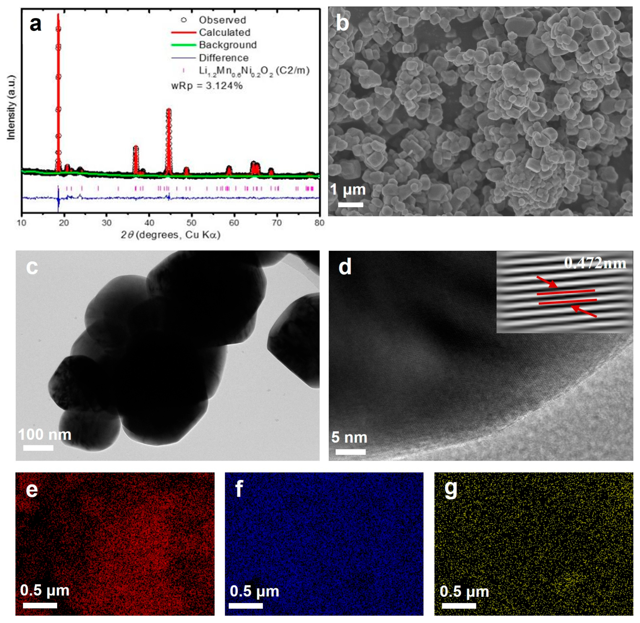
Figure 3.
(a) Photographs of SN-LiClO4 at 80°C and 30°C; (b) Ionic conductivity of PVHLi-1.1/SN-LiClO4; (c) Arrhenius plot of PVHLi-1.1/SN-LiClO4; (d) LSV curve of PVHLi-1.1/SN-LiClO4; (e) DSC curve of SN-LiClO4 electrolyte at a heating rate of 10°C/min; (f) XRD patterns of LiClO4 powder, pure SN, and SN-LiClO4 layer; (g, h) FTIR spectra of SN and SN-LiClO4 layer (2225 - 2300 cm-1); (i) Raman spectra of LiClO4 powder, SN, and SN-LiClO4 layer.
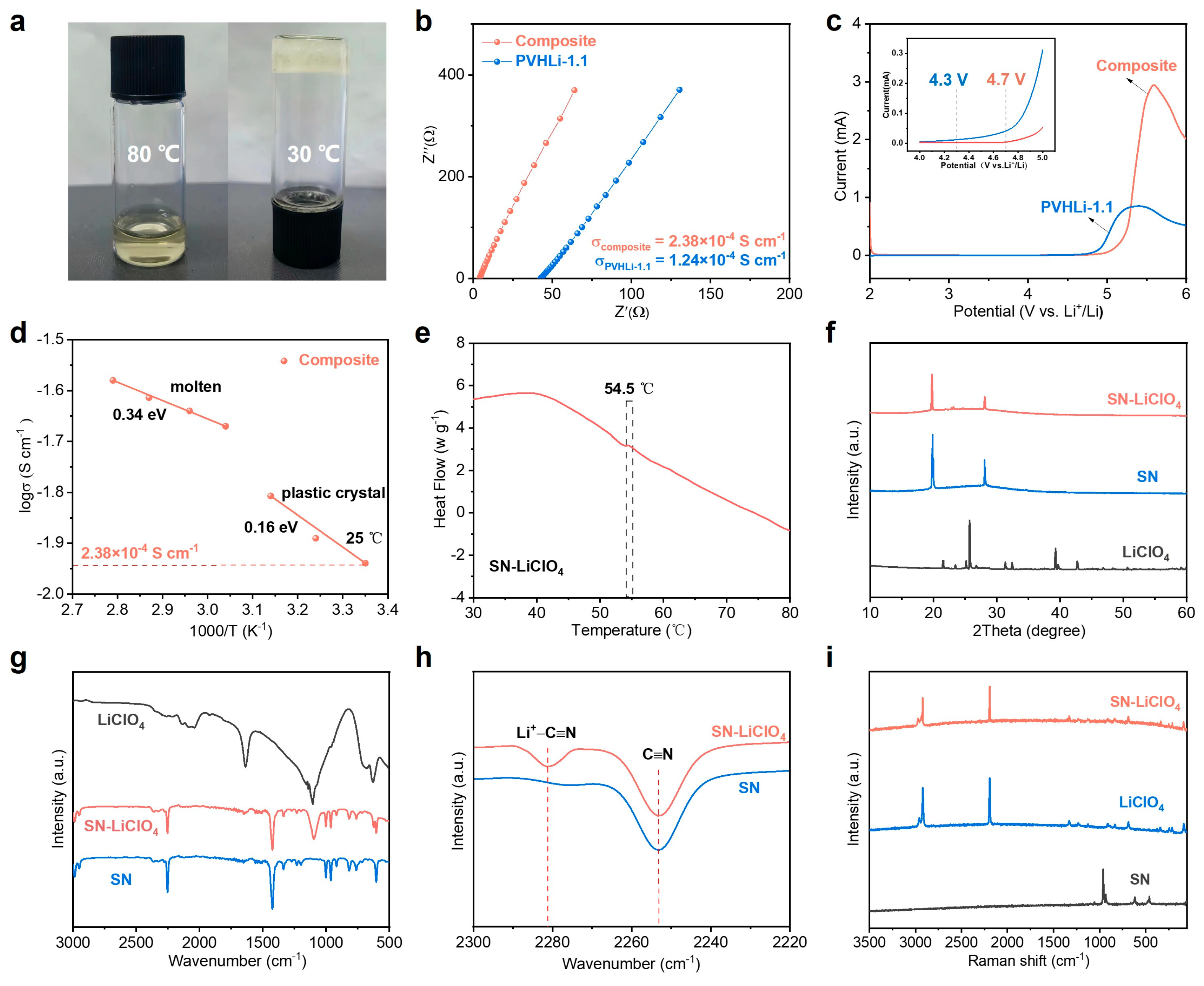
Figure 4.
(a) Schematic illustration of the S-LMNO/PVLi-1.1/Li cell structure; (b) Rate performance of S-LMNO/PVLi-1.1/Li cell at different cutoff voltages under various current densities ranging from 0.05 to 0.5 C; (c-h) Charge-discharge curves with different cutoff voltages of (c) 0.1 C, (e) 0.2 C, and (g) 0.5 C, and (d, f, h) the corresponding specific capacities and coulombic efficiency during cycling. All the electrochemical measurements were taken at 25 ℃.
Figure 5.
(a) Schematic illustration of the pouch cell configuration; (b) Cycling performance of the S-LMNO/PVHLi-1.1/Li cell with a cathode loading of 4.25 mg/cm2; (c-e) Open-circuit voltage of the pouch cell in different states; (f-h) High-voltage Li-rich/Li pouch cell lighting a LED at extreme damage conditions.
Figure 6.
(a, d) O 1s XPS spectra of the ex-situ P-LMNO cathodes cycled to 4.6 V and 2.0 V during the initial cycle; (b, e) O 1s XPS spectra of the ex-situ S-LMNO cathodes cycled to 4.6 V and 2.0 V during the initial cycle; (c, f) Composition analysis of different oxide species at different depth of the LMNO cathodes corresponding to (a, b) and (d, e).

Table 1.
Structural solution of LMNO sample determined by XRD Rietveld refinement.
| Li1.2Mn0.6Ni0.2O2, C2/m, a = 4.954(6) Å, b = 8.563(3) Å, c = 5.030(6) Å , V = 201.4(2), β = 109.25(1)o, Rwp = 3.124% | ||||||
| Atom | Position | Occupancy | Uiso | Multiplicity | ||
| Li1 | 0 | 0.1607(11) | 0 | 0.3 | 0.029(3) | 4 |
| Mn1 | 0 | 0.1607(11) | 0 | 0.7 | 0.029(3) | 4 |
| Ni1 | 0 | 0.5 | 0 | 0.6 | 0.012(4) | 2 |
| Mn2 | 0 | 0.5 | 0 | 0.4 | 0.012(4) | 2 |
| Li3 | 0 | 0 | 0.5 | 1 | 0.035 | 2 |
| Li4 | 0 | 0.66602 | 0.5 | 1 | 0.035 | 4 |
| O1 | 0.238(4) | 0 | 0.257(3) | 1 | 0.013(2) | 4 |
| O2 | 0.232(3) | 0.346(1) | 0.213(1) | 1 | 0.013(1) | 8 |
Disclaimer/Publisher’s Note: The statements, opinions and data contained in all publications are solely those of the individual author(s) and contributor(s) and not of MDPI and/or the editor(s). MDPI and/or the editor(s) disclaim responsibility for any injury to people or property resulting from any ideas, methods, instructions, or products referred to in the content. |
© 2025 by the authors. Licensee MDPI, Basel, Switzerland. This article is an open access article distributed under the terms and conditions of the Creative Commons Attribution (CC BY) license (http://creativecommons.org/licenses/by/4.0/).
Copyright: This open access article is published under a Creative Commons CC BY 4.0 license, which permit the free download, distribution, and reuse, provided that the author and preprint are cited in any reuse.


