Submitted:
14 July 2025
Posted:
15 July 2025
You are already at the latest version
Abstract
This study evaluates the feasibility and benefits of adopting the IEC 62034:2012 standard for Automatic Testing Systems (ATS) for emergency and escape lighting on the BorWin5 High Voltage Direct Current (HVDC) offshore converter platform. The system comprises approximately 1,800 luminaires from multiple manufacturers that are integrated into an open-architecture 220 VDC emergency network. A Multi-Criteria Decision-Making (MCDM) approach was employed to assess the suitability of four configurations, ranging from manual testing to fully automated, centrally powered systems, based on technical, economic and operational criteria. The chosen solution, combining centralised power with automated testing and real-time monitoring, represents a significant advancement in offshore safety infrastructure. Implementing this solution on BorWin5 enhanced reliability and maintainability while ensuring compliance with international standards, supporting a projected service life of over 30 years for an emergency and escape lighting system in an extreme marine environment. The findings offer a scalable model for future offshore platforms operating in similarly challenging conditions.
Keywords:
escape lighting
; emergence lighting
; offshore platform
; IEC 62034:2012 standard
; MCDM
1. Introduction
Depending on the applicable safety standards and the specific operational requirements of the facility, a general lighting system may comprise up to three distinct networks: normal lighting, emergency lighting and escape lighting. The normal lighting network is powered by the primary electrical supply, the emergency lighting network is activated automatically if the main power fails, and the escape lighting network is designed to guide people safely out of an installation during emergencies. Escape lighting operates independently of the main and emergency networks, powered by its own power source, and activates when both the main and emergency systems fail. It is essential in facilities where the main power supply cannot be restored quickly, and where emergency lighting cannot be provided without a blackout via diesel generators or similar. It is also essential in places with high occupancy, such as public buildings. The escape lighting ensures visibility of exit routes, helps reduce panic, and remains on until normal is restored. Emergency and escape lighting play a crucial role in ensuring safety during critical situations [1]. This type of lighting is essential not only in transportation systems, such as aviation and roadways, but also in public buildings and remote areas where electricity supply may be irregular or unavailable where a blackout is a risk for the security [2]. Emergency and escape lighting is becoming increasingly prevalent in modern society and remains a mandatory requirement in all onshore buildings intended for public use, such as hospitals, educational establishments, shopping centers, educational institutions, and factories and warehouses and numerous other facilities [3].
In the offshore sector, the focus of this work, escape and emergency lighting is a critical safety mechanism designed to protect workers and personnel aboard oil rigs, drilling platforms, wind farms, and service vessels operating in remote marine environments. The offshore setting presents unique challenges, including harsh weather conditions and potential hazards such as fires or equipment failures. The complex logistics of maritime operations also present challenges. Therefore, effective lighting systems play a crucial role. Providing clear, accessible lighting during emergencies is essential for facilitating safe and timely evacuations, thereby safeguarding lives and minimizing injuries. In the offshore industry, where response times can be limited by the isolation of operations, emergency and escape lighting systems must be reliable and resilient. They must function effectively under conditions of reduced visibility, such as smoke or water ingress, and during power blackouts.
Thanks to advancements in emergency and escape lighting technology, these systems are becoming more effective and reliable. Current innovations such as smart emergency lighting solutions that utilize LEDs [4,5,6], are designed to provide more energy-efficient and sustainable lighting systems. These systems aim to address issues associated with traditional emergency lighting, such as energy inefficiency and maintenance challenges. Smart emergency and escape lighting systems are characterized by their ability to automatically activate during emergencies and verify their proper functioning even when they are not switched on. These intelligent systems ensure that escape routes are illuminated in real-time, guiding occupants to safety even in challenging visibility conditions. The integration of Internet of Things (IoT) technology is also reshaping the landscape of emergency and escape lighting. IoT-enabled emergency lighting systems can communicate with other safety devices and networks, allowing for a coordinated response during emergencies. These systems can collect data on lighting performance, usage patterns, and potential maintenance issues, ensuring that emergency and escape lights are always operational when needed. Continuous monitoring and automatic alerts for maintenance needs are crucial features that enhance the reliability of emergency lighting [7]. Smart lighting can adapt to different scenarios, such as adjusting light intensity based on occupancy or time of day, thereby maximizing effectiveness while minimizing energy consumption. Such adaptability is especially beneficial in settings where personnel work non-traditional hours, such as night shifts, enabling greater responsiveness to varying operational needs [8,9].
Research emphasizes the importance of human factors in developing these systems, since understanding how people interact with lighting can lead to more effective emergency protocols [10]. While maintenance of escape and emergence lighting traditionally involved manual testing, this is often overlooked today to reduce costs, despite its importance for safety during power outages [11,12]. In the recent years, the introduction of wireless and automatic checking mechanisms facilitates easier monitoring of light performance, ensuring that systems are functional when needed [13,14]. In this sense, the international standard IEC 62034:2012 [15] represents a significant advancement in emergency escape lighting. This standard stipulates performance and safety criteria that automatic test systems must meet, effectively ensuring that emergency and escape lighting functions reliably when it is needed most. A key benefit of implementing this standard is the reduction in preventative maintenance costs associated with these lighting systems [16]. The problem is that the implementation of IEC 62034:2012 has advantages but also disadvantages, especially in terms of cost and complex hardware and software. Accordingly, what are known as multi-criteria decision-making techniques (MCDM) are very useful in decision processes [17,18]. The application of MCDM methods allows decision-makers to systematically compare alternative options based on various criteria. These methods provide structured frameworks for ranking alternatives, grounded in both quantitative and qualitative assessments [19]. The significance of MCDM extends beyond just choosing an alternative. It enhances transparency in the decision-making process, as it accounts for subjective preferences and diverse stakeholder perspectives.
MCDM has countless applications. In this paper, it is applied to the selection of an emergency and escape system for the new building BorWin5 high-voltage direct current (HVDC) offshore converted platform. The motivation stems from the fact that designing and selecting the emergency and escape lighting system for the converter platform in question is critical to ensuring safety within industrial facilities and essential infrastructure. To the authors’ knowledge, offshore platforms constructed to date are equipped with conventional emergency and battery-powered escape lighting techniques. However, these systems have not been implemented in accordance with the IEC 62034:2012 regulation (Automatic Test Systems for Battery-Powered Emergency Escape Lighting). This paper analyses possible solutions for the emergency and escape lighting on the BorWin5 platform and confirms the solution implemented. Additionally, the recently installed emergency and escape lighting system on BorWin5 HVDC is described. This safety system has been engineered using the most advanced technologies currently available on the market to ensure maximum reliability and performance in critical infrastructure applications.
2. Materials and Methods
2.1. Case of Study
In recent years, the offshore wind energy sector has experienced exponential growth, driving significant transformation in the maritime industry and the wider renewable energy sector. This surge has initiated an unprecedented phase of technological and industrial advancement. The continuous increase in wind power generation capacity, coupled with the relocation of wind farms to greater distances offshore, has made the direct transmission of generated energy via low-voltage cables impractical. To address this, offshore electrical substations are being constructed to collect power from wind turbines and transmit it to onshore grids via HVDC systems. In this context, the BorWin5 platform, Figure 1, departed the shipyard in mid-March 2025 and is currently being installed in the North Sea.
BorWin5 is an innovative HVDC offshore converter platform designed to improve connectivity between offshore wind farms in the North Sea and the German power grid. Owned by TenneT Offshore GmbH, it was constructed at the Dragados Offshore yard in Cádiz, Spain. With a transmission capacity of around 900 megawatts (MW), BorWin5 uses voltage-sourced converter (VSC) technology to efficiently and stably convert power between alternating current (AC) and direct current (DC). The platform is part of the BorWin cluster, located off the coast of Germany.
BorWin5 platform is composed of two main elements: the offshore converter platform and the onshore converter station, Figure 2. The offshore converter transforms AC power generated by wind turbines into DC, facilitating efficient long-distance transmission via approximately 120 kilometers of subsea cable. The topsides of the platform weigh around 12,000 tons, while the supporting jacket structure weighs about 7,500 tons. The onshore converter station is located near Emden (Germany). It receives the incoming DC power and converts it back to AC for integration into the national grid. Operating at ±320 kV DC, the system ensures reliable and high-capacity energy transmission.
Not only does BorWin5 demonstrate technical excellence in HVDC transmission, it also sets a new standard in offshore energy infrastructure. It showcases the capability to integrate large-scale renewable energy sources under challenging environmental and operational conditions. Rigorously engineered and custom-designed to meet the stringent technical, environmental and safety criteria intrinsic to offshore operations, it constitutes a step forward in sustainable energy system deployment. This makes BorWin5 a pioneering application of the standard within the offshore power transmission sector.
2.2. Alternatives for the Emergency and Escape Lighting Test System
The emergency and escape lighting of the BorWin5 platform consists of approximately 1,800 luminaires from multiple manufacturers, all powered by a 3x400V+N (main network) and also 220 VDC (emergency network) based on an open-architecture design. Multiple alternatives are available for the testing system, each characterized by distinct features that require thorough evaluation in light of environmental conditions, applicable regulations, and operational demands. The following four were considered in the present work:
- -
- Alternative 1. Traditional Testing of Self-Contained Emergency and Escape Luminaires. This method involves scheduled manual testing of luminaires equipped with integral batteries. It offers flexibility in terms of installation and is simple to implement; however, it requires continuous human intervention for battery status checks and functional verification, increasing operational workload and the potential for human error.
- -
- Alternative 2. Automatic Testing (ATS) of Self-Contained Emergency and Escape Luminaires. This approach integrates automated testing and monitoring protocols directly into self-contained luminaires. By eliminating the need for manual testing, it significantly reduces maintenance demands and improves overall system reliability. Continuous monitoring ensures timely fault detection and enhances compliance with safety regulations.
- -
- Alternative 3. Traditional Testing of Centrally Powered Emergency and Escape Lighting Systems. Under this configuration, a centralized battery system supplies power to multiple luminaires. Manual testing is carried out periodically in accordance with established schedules. Centralized power simplifies battery replacement and lifecycle monitoring, thereby assisting and facilitating maintenance through its centralized structure.
- -
- Alternative 4. Automatic Testing (ATS) of Centrally Powered Emergency and Escape Lighting Systems. This solution incorporates automated testing and diagnostics within a centralized power framework. It enables real-time monitoring and streamlined fault identification, offering enhanced system performance. However, it entails greater infrastructure complexity and a higher initial investment compared to other solutions, as well as the need for skilled professionals to maintain the system.
The investment cost of each alternative was calculated taking into account the following considerations derived from the actual BorWin5 project:
- -
- Luminaire pricing: An average unit price was considered for both emergency luminaires (such as floodlights, technical luminaires, downlights, wall-mounted fixtures, and similar) and escape route luminaires, based on platform design standards.
- -
- Battery pricing: The battery cost was estimated using an average value provided by the manufacturer LIGHTPARTNER for this type of equipment which is the main supplier of luminaires of this platform.
- -
- A 2.5 mm2 cable section was considered for each luminaire, as is standard in this type of installation. A 3G2.5 cable was used for traditional systems in platforms, while a 5G2.5 cable was used for ATS systems, assuming an average distance of 25 meters between luminaires. For centralized systems, it was further assumed that power supply from the battery panels is provided using 35 mm2 cables over a distance of 60 meters. All other auxiliary system cabling (power supplies, heating circuits and automation signals) was estimated as 10% of the total value of the main cabling.
- -
- It was estimated that the entire project of the emergency and escape lighting system should be completed within 4 months with a team of three engineers, whereas autonomous systems are expected to require 5 months.
- -
- The cost of the electrical panels was estimated based on information provided by the supplier for the BorWin 5 project, considering a 30% reduction if the system does not include an automatic control system.
- -
- The cost of the central panels include the inverters, batteries, interconnections and distribution boxes.
- -
- Ilumination software: The involvement of an expert technician in programming was considered for a duration of tree months. This estimation is based on the knowledge acquired during the development of the BorWin5 project.
Figure 3 shows the diferent values of the initial investment corresponding to each alternative.
2.3. Decision Model
As indicated above, a MCDM model was developed to select the most suitable alternative among the four considered. To facilitate this selection, a decision tree was established, Table 5. As shown in this table, the model was structured around three primary criteria:
- -
- cost
- -
- system architecture and design optimization
- -
- operational performance
Each of these criteria was further divided into several sub-criteria. Both beneficial and non-beneficial aspects were included. Beneficial are those for which higher values are preferred, while non-beneficial are those for which lower values are desirable. The nature of each sub-criterion is specified in the last column of the table.
The values corresponding to each sub-criterion are detailed in Table 6. Most of these values were quantified using continuous measurement scales, such as monetary units (euros), time durations (hours), and other metrics. In those cases for which quantitative continuous data could not be obtained, a qualitative assessment was employed using a Likert-type ordinal scale ranging from 1 to 5, where 1 denotes the least favorable performance and 5 the most favorable.
To ensure comparability across criteria with different units and scales, a normalization process was applied to all values. Several normalization procedures can be found in the literature [20]. In the present work, the so-called linear max-min normalization was employed. In this method, the normalised values are given by the following equations:


whereby each Xi.j,k represents the value of the sub-criterion i.j corresponding to the alternative k, Vi.j,k the normalized value of Xi.j,k, Xk,max the maximum grades of the alternatives for each sub-criterion i.j and Xk,min the minimum grades of the alternatives for each sub-criterion i.j.
The linear max-min normalization method transforms all values of a sub-criterion to a [0 1] range, where a value of 0 corresponds to the least favorable outcome and a value of 1 corresponds to the most favorable outcome. Through this procedure, all values are transformed into a dimensionless scale that facilitates unbiased aggregation and comparison. The normalized values for the present work are shown in Table 7.
Several procedures can be used to evaluate and rank the alternatives. In the present work, the Simple Additive Weighting (SAW) method was employed. This is a widely used technique in MCDM approaches due to its simplicity and effectiveness. In this method, the overall performance of each alternative is calculated as a weighted sum of its normalized scores across all sub-criteria, Eq. (3). Given the hierarchical structure of the model, in which each main criterion comprises multiple sub-criteria, the adequacy index (AI) for each alternative is computed by aggregating the weighted contributions of all sub-criteria, nested within their respective main criteria, as shown in Eq. (3). When the SAW method is used with linear max-min normalized values, the adequacy index for falls within the [0, 1] range. A value close to 1 indicates a highly suitable alternative, while a value close to 0 indicates a less suitable one.

whereby AIk is the adequacy index for alternative k, αi is the weight (per unit basis) of the i-th main criterion, βi.j is the weight (per unit basis) of the j-th sub-criterion under criterion i, Vi.j,k is the normalized value of the j-th sub-criterion of criterion i for alternative k, n is the number of main criteria, and mi is the number of sub-criteria under criterion i.
3. Results and Discussion
An important aspect of MCDM is establishing the weights assigned to each criterion and sub-criterion. These weights represent the importance given to each aspect. There are numerous objective methods available in the literature for determining weights using mathematical formulas. However, subjective weighting approaches are more frequently used. Objective methods are especially advisable when there is no consensus among the expert-defined weight sets [21,22]. In the present work, the weights were established based on what is known as expert citation. The weights are shown in Table 8. It is important to note that a sensitivity analysis of the assigned weights is shown at the end of this section.
As can be seen in Table 8, a weight of 45% was assigned to cost, a 20% to system architecture and device optimization, and 35% to functionability and operability. Obviously, the sum of the weights assigned to all the criteria must add up to 100, i.e.,  . Similarly, weights were also been assigned to the sub-criteria. The sum of
weights of the sub-criteria must also add up to 100 for each criterion,
. Similarly, weights were also been assigned to the sub-criteria. The sum of
weights of the sub-criteria must also add up to 100 for each criterion,  .
.
. Similarly, weights were also been assigned to the sub-criteria. The sum of
weights of the sub-criteria must also add up to 100 for each criterion, .Based on the application of the SAW method described in the previous section, the AIs corresponding to each alternative were computed aggregating the weighted and normalized scores across all sub-criteria. The results of applying Equation (3) are shown in Table 9.
The resulting indices shown in this table provide a quantitative measure of how well each alternative satisfies the defined evaluation criteria. These values, which range between 0 and 1, allow for a straightforward comparison: alternatives with higher adequacy indices are considered more suitable according to the model. The rankings are shown in brackets in the table. The computed results reveal clear differences in performance among the alternatives, thereby supporting an informed and transparent decision-making process. As can be seen, alternative 4 resulted to be the best option with the first position, alternative 2 with the second position, alternative 3 the third position and the least recommended option, alternative 1, with the fourth and last position in the ranking.
It is worth mentioning that the AI calculated using Equation (3) can be broken down into three distinct sub adequacy indices, each corresponding to one of the key criteria analyzed: cost, system architecture and design optimization, and operational performance. In this sense, the method can enable the assessment of how each alternative contributes individually to these three pillars. As such, it is possible to derive an economic index (AIcost), a system architecture and design optimization index (AIsystem), and an operational performance index (AIperformance). These sub-indices are also determined using Equation (3), but by considering only the sub-criteria associated with each specific dimension. Table 10 presents the overall AI along with its corresponding sub-indices for the evaluated alternatives. Positions are indicated in brackets. This information is also graphically shown in Figure 4. As can be seen, alternatives 2 and 4 present notably suitability in terms of performance (AIperformance), while alternatives 3 and 4 stand out in the economic criterion. Alternative 1 has low values for the three criteria considered (AIcost, AIsystem and AIperformance).
It is important to highlight that MCDM methods are inherently influenced by subjectivity, and SAW is no exception. Subjectivity primarily arises when assigning weights. As a result, applying Eq. (3) may yield different outcomes depending on these inputs. However, while the exact numerical results might vary, the overall ranking of alternatives should remain largely consistent—provided that the weights and value functions are reasonably chosen. Shifts in ranking are typically limited to alternatives with very similar input values and performance. Likewise, the gap between the adequacy indices of two alternatives may vary with different input assumptions, although the proportional relationship between them tends to be preserved to some degree. To address these uncertainties, conducting a sensitivity analysis—such as the one carried out in this study—is a recommended approach. A weight sensitivity analysis was carried out by analysing six cases with different weight combinations, shown in Table 11. Visually, this information is represented in Figure 5. As can be seen, the adequacy indices change slightly according to the different weight distributions. Regarding the positions of each alternative, these remain practically unchanged. Alternative 4 appears as the most adequate option in the six cases analysed. This indicates that the model is robust in that small changes in the weights do not significantly affect the results.
In conclusion, based on the comprehensive analysis presented, alternative 4 emerges as the most adequate solution for emergency and escape lighting on BorWin5 offshore platform. This alternative, which combines centralized power supply with automated testing and monitoring systems, offers significant advantages in terms of reliability, maintenance efficiency, and compliance with stringent offshore safety standards. Accordingly, alternative 4 was selected and successfully implemented on the BorWin5 platform, demonstrating its effectiveness in meeting the unique technical, environmental, and operational challenges inherent to offshore installations. The details are provided in Appendix A.
4. Conclusions
This study demonstrates that the implementation of automatic testing systems for emergency and escape central lighting, in accordance with IEC 62034:2012, offers a robust and future-proof solution for offshore platforms operating in demanding environments. Through a comprehensive multi-criteria decision-making (MCDM) analysis, four alternative configurations were evaluated based on cost, system architecture, and operational performance. The results clearly identified the automatic testing of centrally powered systems as the most suitable option, offering superior reliability, maintainability, and integration capabilities.
The successful deployment of this solution on the BorWin5 HVDC converter platform validates its technical and economic feasibility. Key innovations—such as the use of a 220 VDC emergency network, open-architecture network, real-time monitoring, and DALI-based interoperability—highlight the system’s adaptability and long-term scalability. Moreover, the adoption of an open communication protocol breaks away from vendor lock-in, enabling flexible integration of multi-brand luminaires and enhancing lifecycle sustainability.
This work not only advances the implementation of the IEC 62034:2012 standard on the BorWin5 platform, but also provides a replicable framework for future offshore infrastructure projects. The BorWin5 case study serves as a reference for the modernization of emergency and escape lighting systems in critical offshore installations.
Author Contributions
Conceptualization, L.G.R. and M.I.L.; methodology, L.G.R., J.J.C.B. and L.C.S.; software, L.G.R. and J.J.C.B, formal analysis, L.G.R., M.I.L, and L.C.S.; investigation, L.G.R., M.I.L, J.J.C.B. and L.C.S.; resources, L.C.S.; writing—original draft preparation, L.G.R., J.J.C.B. and M.I.L.; writing—review and editing, M.I.L. and L.C.S.; supervision, L.C.S. and M.I.L.G. All authors have read and agreed to the published version of the manuscript.
Funding
This research was partially funded by Project 101181231 “Multi-disciplinary risk management for stable, safe, and sustainable offshore wind-powered hydrogen production” (WINDHY), financed by the European Commission under the Marie Skłodowska-Curie (MSCA) Staff Exchanges Actions of the Horizon Europe. This research was also partially funded by Project TED2021-132534B–I00 funded by MICIU/AEI/ 10.13039/501100011033 and by the “European Union NextGenerationEU/PRTR”. Besides, this study contributes to the international project 3E-Partnership (proposal number 101128576) funded with support from the European Commission under the Action ERASMUS-LS and the Topic ERASMUS-EDU-2023-CBHE-STRAND-2.
Institutional Review Board Statement
Not applicable.
Informed Consent Statement
Not applicable.
Acknowledgements
The authors would like to thank Adrián Abelleira Rodríguez of Norispan S.L. for his kind assistance and help.
Conflicts of Interest
The authors declare no conflicts of interest.
Appendix A. Emergency and Escape Lighting System of BorWin5
The emergency and escape lighting system of BorWin5 platform was developed in Spain by the company Norispan S.L. It incorporates a comprehensive testing and monitoring framework capable of reporting the operational status of each installed luminaire. Monitoring can be conducted either locally via a Human-Machine Interface (HMI) or remotely through integration with the platform’s automation system, both onshore and offshore. The system is fully compliant with the IEC 62034:2012 standard, which specifies requirements for automatic testing systems for battery-powered emergency escape lighting.
The emergency and escape lighting system is powered via dual redundant sources: the emergency power supply system at 400 V AC and the 220 V DC battery system. These sources interconnect through a Battery Connection Box incorporating diode isolation to prevent reverse current flow, thereby ensuring uninterrupted power delivery under fault conditions.
In the event of failure of either power source, no less than 30% of the lighting fixtures within each compartment or designated zone maintain full operational functionality. The illumination provided under these conditions does not fall below the minimum required for safe escape and rescue route lighting as stipulated by applicable safety regulations.
The emergency and escape lighting system activates automatically and operates in continuous mode, maintaining constant illumination until normal power is restored and the system is reset.
The emergency lighting system is engineered such that any failure, including fire or other casualty within spaces housing the emergency power sources—such as transformers, converters, or associated electrical equipment—does not result in the loss of illumination provided by the main lighting system. The system guarantees adequate residual illumination levels to satisfy safety requirements during a general lighting outage.
The emergency and escape lighting system consists of the components shown in Table A1 and Figure A1, supplied by Norispan S.L.

Table A1.
Components of the emergence and escape lighting.
| Distribution panels | Central emergency lighting switchboard |
| Sub-distribution emergency lighting switchboard | |
| Central escape lighting switchboard | |
| Sub-distribution escape lighting switchboard | |
| 220Vdc/3x400V+N inverters | Emergency inverter |
| Escape inverter | |
| Approximately 1,800 luminaires equipped with DALI drivers for the emergency and escape networks | |
Figure A1.
Layout of the emergency and escape lighting.
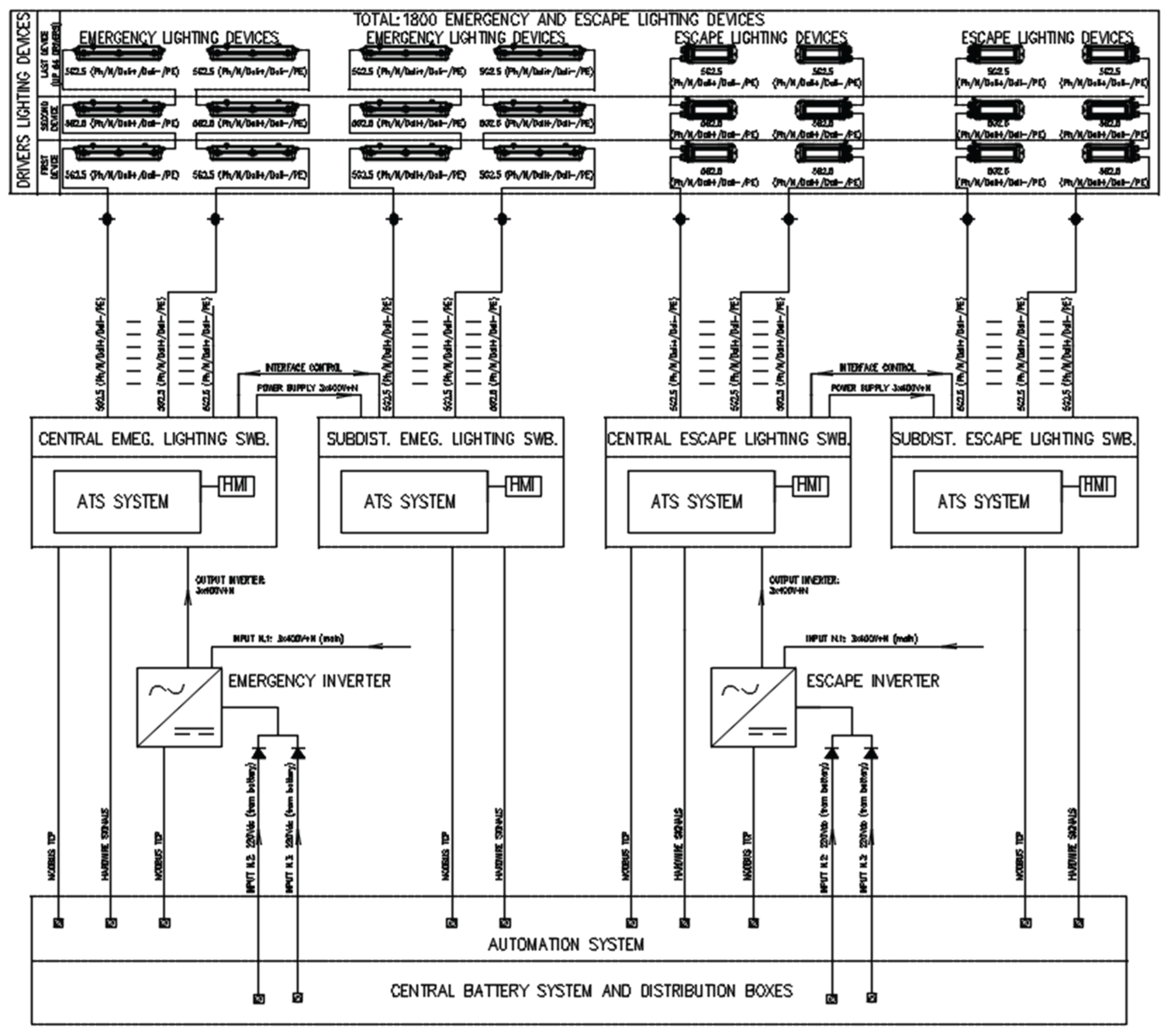
The Emergency/Escape Subdistribution Boards are supplied from the Central Panels via a single incomer. Under normal operating conditions, the emergency and escape lighting system receives power from the emergency distribution board (via the main switchboard) and remains continuously energized.
The emergency and escape lighting system is designed to supplement the platform’s normal lighting, with an approximate ratio of 2:1—meaning that for every emergency and escape luminaire, two normal lighting luminaires are installed, resulting in a total of approximately 1,800 luminaires.
All emergency lighting fixtures are LED-type and were selected in compliance with platform standards and the applicable regulations of the DNV GL Classification Society [23]. Key environmental conditions—such as humidity, temperature, corrosion resistance, ingress protection, illuminance levels, and a required service life of 30 years—were critical factors in the selection of equipment.
As previously mentioned, all installed lighting deviced are monitored both through the automation system of the system which is intefaced with the automation system of the platform. For this reason, all luminaires are equipped with DALI-2 drivers. All luminaires are capable of operating at both 230 V AC and 220 V DC (via inverter).
One of the main advantages of the developed design is the use of luminaires from multiple marine-grade suppliers, with full interoperability between them—made possible through DALI technology.
References
- W. Li, Y. W. Li, Y. Wang, Z. Ye, Y. A. Liu, and L. Wang, “Development of a mixed reality assisted escape system for underground mine- based on the mine water-inrush accident background,” Tunn. Undergr. Sp. Technol., vol. 143, p. 105471, Jan. 2024. [Google Scholar] [CrossRef]
- Q. Zhang, J. Q. Zhang, J. Zhou, J. Liu, and Y. Zhang, “Design of a ship light environment control system,” in 3rd International Conference on Artificial Intelligence, Automation, and High-Performance Computing (AIAHPC 2023), Jul. 2023, p. 42. [CrossRef]
- L. C. Towle, “An analysis of the overall integrity of an escape route lighting system,” in Fifth International Conference on `Electrical Safety in Hazardous Environments’, 1994, vol. 1994, pp. 239–244. [CrossRef]
- S. Mukherjee, P. S. Mukherjee, P. Satvaya, and S. Mazumdar, “Development of a Microcontroller Based Emergency Lighting System with Smoke Detection and Mobile Communication Facilities,” Light Eng., pp. 46–50, Feb. 2019. [Google Scholar] [CrossRef]
- G. Wati et al., “Analysis of Generator Power Requirements for Lighting Distribution Using LED Lights on a 500 DWT Sabuk Nusantara,” Indones. J. Marit. Technol., vol. 1, no. 2, Dec. 2023. [CrossRef]
- S. Suardi, A. Y. S. Suardi, A. Y. Kyaw, A. I. Wulandari, and F. Zahrotama, “Impacts of Application Light-Emitting Diode (LED) Lamps in Reducing Generator Power on Ro-Ro Passenger Ship 300 GT KMP Bambit,” Int. J. Mech. Eng. Sci., vol. 7, no. 1, p. 44, Mar. 2023. [Google Scholar] [CrossRef]
- N. Balfe, S. N. Balfe, S. Sharples, and J. R. Wilson, “Understanding Is Key: An Analysis of Factors Pertaining to Trust in a Real-World Automation System,” Hum. Factors J. Hum. Factors Ergon. Soc., vol. 60, no. 4, pp. 477–495, Jun. 2018. [Google Scholar] [CrossRef]
- S. Narasimha and S. R. Salkuti, “Design and development of smart emergency light,” TELKOMNIKA (Telecommunication Comput. Electron. Control., vol. 18, no. 1, p. 358, Feb. 2020. [CrossRef]
- Lowden and, G. Kecklund, “Considerations on how to light the night-shift,” Light. Res. Technol., vol. 53, no. 5, pp. 437–452, Aug. 2021. [Google Scholar] [CrossRef]
- Gritsuk, P. Nosov, O. Dyagileva, and M. Masonkova, “Improving safety of navigation by constructing a dynamic model of the navigator’s actions in the conditions of navigation risks,” Collect. Sci. Work. State Univ. Infrastruct. Technol. Ser. “Transport Syst. Technol., no. 41, pp. 84–95, Jun. 2023. [Google Scholar] [CrossRef]
- E. Aizlewood and G. M. B. Webber, “Escape route lighting: Comparison of human performance with traditional lighting and wayfinding systems,” Light. Res. Technol., vol. 27, no. 3, pp. 133–143, Sep. 1995. [CrossRef]
- M. Fuchtenhans, E. H. M. Fuchtenhans, E. H. Grosse, and C. H. Glock, “Literature review on smart lighting systems and their application in industrial settings,” in 2019 6th International Conference on Control, Decision and Information Technologies (CoDIT), Apr. 2019, pp. 1811–1816. [CrossRef]
- H.-C. Lin, L.-Y. H.-C. Lin, L.-Y. Liu, W.-L. Luo, and M.-N. Chi, “Development of Wireless Automatic Checking Handset for Wide-Distributed Emergency Lights,” Meas. Control, vol. 46, no. 7, pp. 213–220, Sep. 2013. [Google Scholar] [CrossRef]
- H. C. Lin, M. N. H. C. Lin, M. N. Chi, and W. L. Luo, “Achievement of a wireless portable apparatus for self-checking emergency lights,” IEEJ Trans. Electr. Electron. Eng., vol. 11, no. 6, pp. 812–819, Nov. 2016. [Google Scholar] [CrossRef]
- ”IEC 62034:2012; Automatic Test Systems for Battery Powered Emergency Escape Lighting; International Electrotechnical Commission: Geneva, Switzerland, 2012.
- L. García Rodríguez, L. L. García Rodríguez, L. Castro-Santos, and M. I. Lamas Galdo, “Techno-Economic Analysis of the Implementation of the IEC 62034:2012 Standard—Automatic Test Systems for Battery-Powered Emergency Escape Lighting—In a 52.8-Meter Multipurpose Vessel,” Eng, vol. 6, no. 6, p. 110. May; 25. [CrossRef]
- J. Lin, S.-W. J. Lin, S.-W. Huang, H.-Y. Chang, J.-B. Sheu, and G.-H. T. Tzeng, “FACTORS INFLUENCING FOLLOW-ON PUBLIC OFFERING OF SHIPPING COMPANIES FROM INVESTOR PERSPECTIVE – A HYBRID MULTIPLE-CRITERIA DECISION-MAKING APPROACH,” Technol. Econ. Dev. Econ., vol. 30, no. 4, pp. 1087–1119, Jun. 2024. [Google Scholar] [CrossRef]
- J. Lin, H.-Y. J. Lin, H.-Y. Chang, and B. Hung, “Identifying Key Financial, Environmental, Social, Governance (ESG), Bond, and COVID-19 Factors Affecting Global Shipping Companies—A Hybrid Multiple-Criteria Decision-Making Method,” Sustainability, vol. 14, no. 9, p. 5148, Apr. 2022. [Google Scholar] [CrossRef]
- S. K. Sahoo and S. S. Goswami, “A Comprehensive Review of Multiple Criteria Decision-Making (MCDM) Methods: Advancements, Applications, and Future Directions,” Decis. Mak. Adv., vol. 1, no. 1, pp. 25–48, Dec. 2023. [CrossRef]
- G. Rodríguez, M. I. G. Rodríguez, M. I. Lamas, J. de D. Rodríguez, and C. Caccia, “ANALYSIS OF THE PRE-INJECTION CONFIGURATION IN A MARINE ENGINE THROUGH SEVERAL MCDM TECHNIQUES,” Brodogradnja, vol. 72, no. 4, pp. 1–17, Dec. 2021. [Google Scholar] [CrossRef]
- Vinogradova, V. Podvezko, and E. Zavadskas, “The Recalculation of the Weights of Criteria in MCDM Methods Using the Bayes Approach,” Symmetry (Basel)., vol. 10, no. 6, p. 205, Jun. 2018. [Google Scholar] [CrossRef]
- M. I. Lamas, L. M. I. Lamas, L. Castro-Santos, and C. G. Rodriguez, “Optimization of a Multiple Injection System in a Marine Diesel Engine through a Multiple-Criteria Decision-Making Approach,” J. Mar. Sci. Eng., vol. 8, no. 11, p. 946, Nov. 2020. [Google Scholar] [CrossRef]
- ”DNV. Rules for Classification. Ships. DNV GL: Høvik, Norway, 2021.
Figure 1.
BorWin5 platform during its transfer to the North Sea.
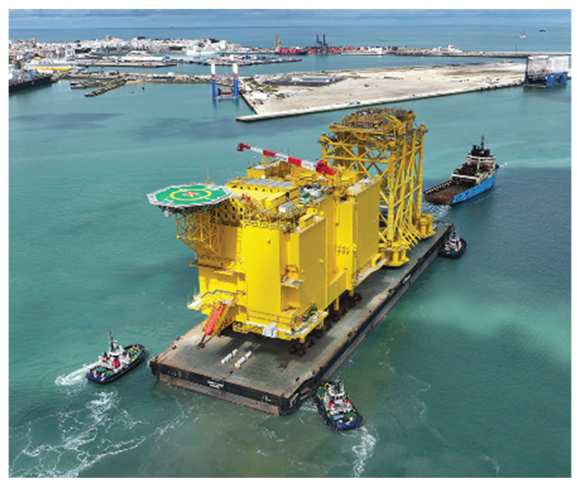
Figure 2.
Location of the BorWin5 platform.
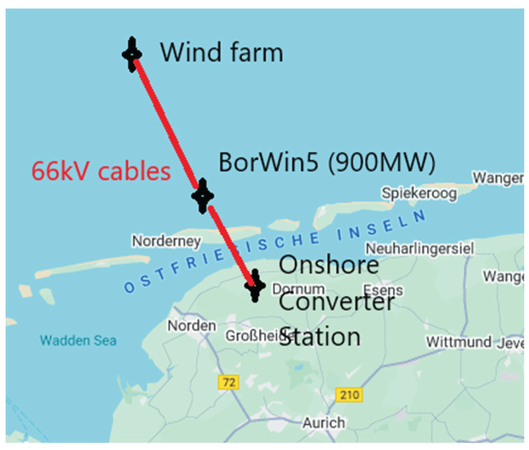
Figure 3.
Investment costs of the four alternatives analyzed.
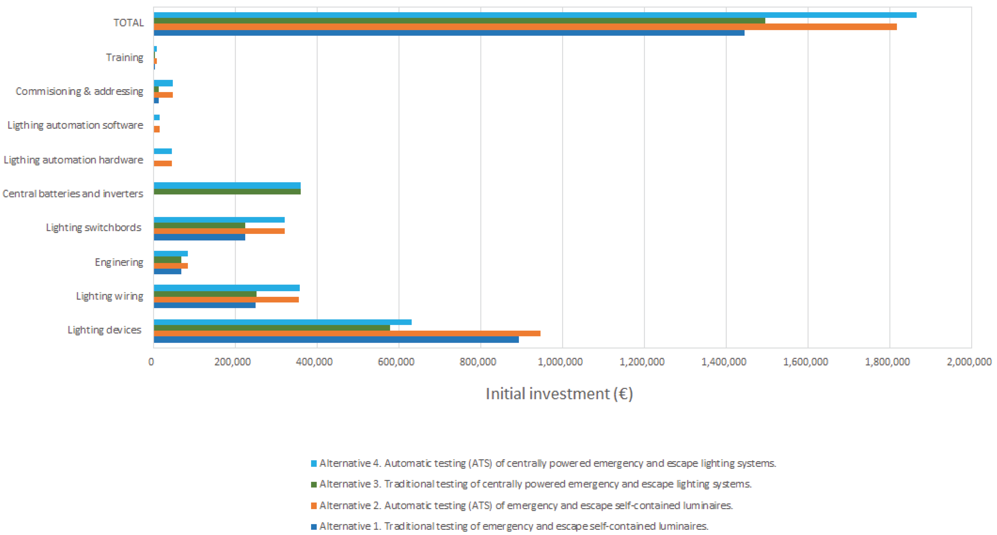
Figure 4.
Results of total and partial adequacy indices.
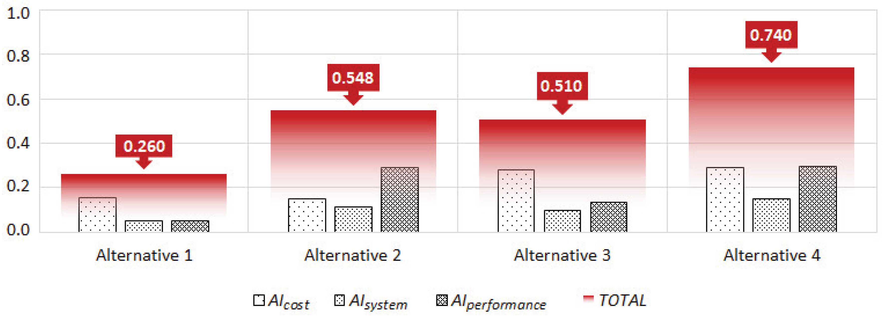
Figure 5.
Comparison results of ranking alternatives.
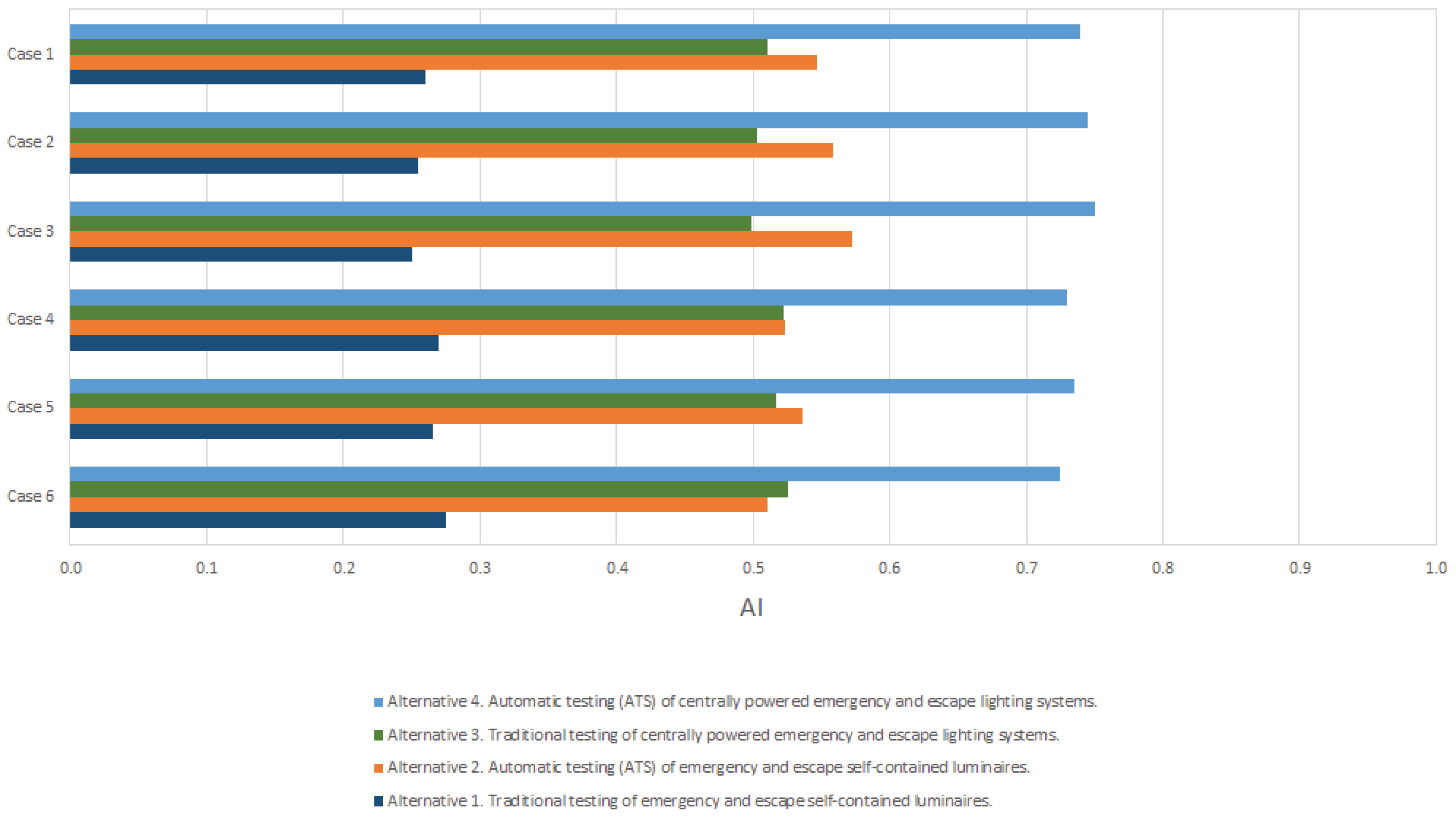
Table 1.
Advantages of alternative 1 (traditional testing of emergency and escape self-contained luminaires) compared to the other alternatives.
Table 1.
Advantages of alternative 1 (traditional testing of emergency and escape self-contained luminaires) compared to the other alternatives.
| Advantages | Comparison to the other alternatives |
|---|---|
| Lower initial investment compared to ATS | Unlike ATS (alternatives 2 and 4), traditional testing requires no automated control components, diagnostic systems, or communication modules, significantly reducing capital expenditure. |
| Low technical complexity | Unlike centralized systems (alternatives 3 and 4), and automated self-contained luminaires (alternative 2), this approach does not require complex configurations, making it easier to install. |
| Independence and fault containment | Similar to alternative 2 and unlike alternatives 3 and 4, self-contained luminaires function independently. In the event of a failure, the issue is isolated to a single unit, with no impact on other luminaires or circuits. |
| No dependency on central infrastructure | Unlike alternatives 3 and 4, traditional self-contained luminaires do not rely on centralized battery systems, power distribution panels, or extended cabling, making them highly suitable for modular or remote installations. |
| Ideal for small-scale installations | In installations where the number of luminaires is limited, the simplicity and low cost of manual testing offer a practical and efficient solution compared to more sophisticated (and costly) automated or centralized alternatives. |
Table 2.
Advantages of alternative 2 (automatic testing of emergency and escape self-contained luminaires) compared to the other alternatives.
Table 2.
Advantages of alternative 2 (automatic testing of emergency and escape self-contained luminaires) compared to the other alternatives.
| Advantages | Comparison to the other alternatives |
|---|---|
| Automated compliance and reduced human error | Unlike alternatives 1 and 3, the ATS function ensures periodic tests (function and duration) are performed automatically according to pre-defined schedules, minimizing the risk of missed inspections, human oversight, or non-compliance with regulatory requirements. |
| Enhanced fault detection and reporting | Unlike traditional systems (alternatives 1 and 3), ATS systems automatically detect, log, and report failures of each addressing luminaries in real time, providing clear and timely diagnostics that support preventive maintenance and reduce downtime. |
| Retention of luminaire independence | Unlike centrally powered systems (alternatives 3 and 4), self-contained luminaires operate independently. A failure in one luminaire does not compromise the functionality of the overall system, enhancing operational reliability in safety-critical environments. |
| Simplified infrastructure compared to centralized systems | Unlike alternatives 3 and 4, this solution does not require central battery systems, power distribution battery networks, or additional cabling, reducing installation complexity and cost, particularly in retrofitting or offshore modular applications. |
| Lower long-term operational costs | Although the initial investment may be higher than traditional test, the reduction in manual labor and increased efficiency in maintenance activities typically result in lower lifecycle costs compared to traditional testing methods. |
| Improved data logging and maintenance planning | Compared to manual systems, ATS provides a continuous log of system performance, supporting maintenance planning, trend analysis, and facilitating documentation for compliance with standards. |
| Suitable for distributed and isolated installations | Unlike centralized systems (alternatives 3 and 4), ATS-enabled self-contained luminaires are well suited for installations with spatial constraints or segmented layouts—common in offshore units—where centralized cabling and control may be impractical. |
Table 3.
Advantages of alternative 3 (traditional testing of centrally powered emergency and escape lighting systems) compared to the other alternatives.
Table 3.
Advantages of alternative 3 (traditional testing of centrally powered emergency and escape lighting systems) compared to the other alternatives.
| Advantages | Comparison to the other alternatives |
|---|---|
| Lower initial investment compared to ATS | While offering the benefits of centralized power management, this alternative avoids the additional cost of automation infrastructure required in alternatives 2 and 4 (ATS), making it a more economical solution for projects with budget constraints. |
| Simplified system architecture compared to self-contained solutions | Unlike alternatives 1 and 2, the central battery system eliminates the need for each luminaire to be equipped with its own power source. This centralization can simplify power maintenance and lifecycle battery replacement logistics. |
| Unified battery maintenance | With a centralized power source, battery testing, charging, and replacement are managed at a single location—unlike self-contained systems (alternatives 1 and 2), where batteries must be individually maintained and monitored. |
| Suitable for high-density lighting installations | In facilities or offshore units with large concentrations of emergency and escape luminaires, a centralized system may offer a more efficient and structured approach to power management than distributed self-contained units. |
| Lower complexity than ATS systems in terms of software and configuration | Compared to alternatives 2 and 4, traditional centralized systems do not require automated testing protocols or software-based monitoring, reducing system setup complexity and potential cybersecurity risks. |
Table 4.
Advantages of alternative 4 (automatic testing of centrally powered emergency and escape lighting systems) compared to the other alternatives.
Table 4.
Advantages of alternative 4 (automatic testing of centrally powered emergency and escape lighting systems) compared to the other alternatives.
| Advantages | Comparison to the other alternatives |
|---|---|
| Centralized monitoring and management | Unlike self-contained systems (alternatives 1 and 2), centrally powered ATS systems allow for centralized supervision, enabling real-time fault detection, test result logging, and streamlined maintenance management from a single control point. |
| Automated testing without manual intervention | Unlike traditional testing methods (alternatives 1 and 3), ATS systems perform scheduled functional and autonomy tests automatically, ensuring continuous compliance with safety regulations without relying on manual inspections. |
| Reduced long-term operational costs | Automation and centralized battery infrastructure reduce the need for individual inspections and interventions, leading to significant cost savings over the lifecycle of the system. |
| Optimized energy and battery management | Compared to self-contained luminaires (alternatives 1 and 2), centrally powered systems offer more efficient energy distribution and centralized control of battery charging, discharging, and health monitoring. |
| Scalability and suitability for complex installations | Ideal for large-scale or high-density lighting installations, where managing numerous individual units would be impractical. Centralized systems provide structured and scalable solutions. |
| Integration with Building Management Systems (BMS) or offshore automation system | Unlike traditional systems, ATS centrally powered solutions can be integrated with BMS or other facility management platforms, enabling remote diagnostics, alarm notifications, and full traceability of system performance. Artificial intelligence protocols may be integrated into the automation system by leveraging the continuous monitoring of the luminaires, thereby enabling adaptive and data-driven decision-making. |
| Architectural and technical design flexibility | In emergency and escape lighting, many emergency luminaires—such as projectors, downlights, and recessed fittings with elevated power consumption— are not designed to house an internal battery but also serve architectural or decorative purposes. In such cases, self-contained luminaires (alternatives 1 and 2) would require built-in batteries, which often complicate the luminaire design, increase its size significantly, and negatively impact its aesthetics or architectural integration. A centrally powered system overcomes this limitation by allowing for compact, visually refined luminaires without internal batteries, thus preserving both performance and design intent. |
Table 5.
Decision tree for the MCDM model.
| Criterion | Sub-criterion | Beneficial |
|---|---|---|
| 1. Cost | 1.1 Initial capital expenditure | ✕ |
| 1.2 Time of preventive maintenance testing | ✕ | |
| 1.3 Long-term operational costs | ✕ | |
| 1.4 Luminaire service life | ✓ | |
| 1.5 Frequency of battery replacement | ✕ | |
| 1.6 Requirement of personnel with high technical expertise | ✕ | |
| 2. System architecture and device optimization | 2.1 Wire cables | ✕ |
| 2.2 No dependency on central infrastructure | ✕ | |
| 2.3 Luminaire weight optimization | ✕ | |
| 2.4 Suitability for high-density luminaire configurations | ✓ | |
| 2.5 Reduction of electrical number switchboards | ✕ | |
| 2.6 Streamlined luminaire design | ✓ | |
| 3. Operational performance |
3.1 Interface with other systems (BMS, ICMS,….) | ✓ |
| 3.2 Influence of human error | ✕ | |
| 3.3 Fault isolation and discrimination | ✓ | |
| 3.4 Optimized data dogging and maintenance management | ✓ | |
| 3.5 Reliability of monthly functional test performance | ✓ | |
| 3.6 Reliability of yearly duration test performance | ✓ | |
| 3.7 Time of fault detection | ✓ |
Table 6.
Values of each sub-criterion.
| Sub-criterion(i.j) | Unit | Alternative 1(k = 1) | Alternative 2(k = 2) | Alternative 3(k = 3) | Alternative 4(k = 4) |
|---|---|---|---|---|---|
| 1.1 | € | 1445.240 | 1818.310 | 1495.663 | 1865.945 |
| 1.2 | hour | 2250 | 250 | 1350 | 250 |
| 1.3 | ratio 3:1 (traditional test/ATS) |
3 | 2 | 3 | 1 |
| 1.4 | hour | 61320 | 61320 | 175200 | 219000 |
| 1.5 | number of battery replacements every 5 years/7 | 1800 | 1800 | 200 | 200 |
| 1.6 | €/month | 1666 | 2540 | 1666 | 2540 |
| 2.1 | kg | 7920 | 11880 | 8202.48 | 12162.48 |
| 2.2 | - | 5 | 3 | 3 | 1 |
| 2.3 | kg | 7182 | 7182 | 5760 | 5760 |
| 2.4 | - | 1 | 4 | 2 | 5 |
| 2.5 | switchboards | 4 | 4 | 8 | 8 |
| 2.6 | - | 1 | 3 | 4 | 5 |
| 3.1 | - | 1 | 5 | 3 | 5 |
| 3.2 | - | 1 | 5 | 2 | 5 |
| 3.3 | - | 1 | 4 | 3 | 5 |
| 3.4 | - | 1 | 5 | 2 | 5 |
| 3.5 | - | 1 | 5 | 2 | 5 |
| 3.6 | - | 1 | 5 | 2 | 5 |
| 3.7 | - | 1 | 5 | 2 | 5 |
Table 7.
Normalized values of each sub-criterion.
| Sub-criterion(i.j) | Alternative 1(k = 1) | Alternative 2(k = 2) | Alternative 3(k = 3) | Alternative 4(k = 4) |
|---|---|---|---|---|
| 1.1 | 1 | 0.113 | 0.88 | 0 |
| 1.2 | 0 | 1 | 0.45 | 1 |
| 1.3 | 0 | 0.5 | 0 | 1 |
| 1.4 | 0 | 1 | 0.722 | 1 |
| 1.5 | 0 | 0 | 1 | 1 |
| 1.6 | 1 | 0 | 1 | 0 |
| 2.1 | 1 | 0.067 | 0.933 | 0 |
| 2.2 | 1 | 0.788 | 0.091 | 0 |
| 2.3 | 0 | 0 | 1 | 1 |
| 2.4 | 0 | 0.75 | 0.25 | 1 |
| 2.5 | 1 | 1 | 0 | 0 |
| 2.6 | 0 | 0.5 | 0.75 | 1 |
| 3.1 | 0 | 1 | 0.5 | 1 |
| 3.2 | 1 | 0 | 0.75 | 0 |
| 3.3 | 0 | 0.75 | 0.5 | 1 |
| 3.4 | 0 | 1 | 0.25 | 1 |
| 3.5 | 0 | 1 | 0.25 | 1 |
| 3.6 | 0 | 1 | 0.25 | 1 |
| 3.7 | 0 | 1 | 0.25 | 1 |
Table 8.
Criteria weights.
| Criterion | Criterion weight | Sub-criterion | Sub-criterion weight |
|---|---|---|---|
| 1. Cost | α1 = 45% | 1.1 Initial capital expenditure | β1.1 = 25% |
| 1.2 Time of preventive maintenance testing | β1.2 = 20% | ||
| 1.3 Long-term operational costs | β1.3 = 20% | ||
| 1.4 Luminaire service life | β1.4 = 15% | ||
| 1.5 Frequency of battery replacement | β1.5 = 10% | ||
| 1.6 Requirement of personnel with high technical expertise | β1.6 = 10% | ||
| 2. System architecture and device optimization | α2 = 20% | 2.1 Wire cables | β2.1 = 10% |
| 2.2 Independency on central infrastructure | β2.2 = 20% | ||
| 2.3 Luminaire weight optimization | β2.3 = 10% | ||
| 2.4 Suitability for high-density luminaire configurations | β2.4 = 30% | ||
| 2.5 Reduction of electrical number switchboards | β2.5 = 15% | ||
| 2.6 Streamlined luminaire design | β2.6 = 15% | ||
| 3. Operational performance | α3 = 35% | 3.1 Interface with other systems (BMS, ICMS,….) | β3.1 = 15% |
| 3.2 Influence of human error | β3.2 = 15% | ||
| 3.3 Fault isolation and discrimination | β3.3 = 10% | ||
| 3.4 Optimized data dogging and maintenance management | β3.4 = 15% | ||
| 3.5 Reliability of monthly functional test performance | β3.5 = 15% | ||
| 3.6 Reliability of yearly duration test performance | β3.6 = 15% | ||
| 3.7 Time of fault detection | β3.7 = 15% |
Table 9.
Adequacy indices corresponding to each alternative.
| Alternative (k) | AI |
|---|---|
| Alternative 1 | 0.260 (4th) |
| Alternative 2 | 0.548 (2nd) |
| Alternative 3 | 0.510 (3rd) |
| Alternative 4 | 0.740 (1st) |
Table 10.
Detailed results and rankings.
| Alternative (k) | Adequacy indices | |||
|---|---|---|---|---|
| AIcost | AIsystem | AIperformance | AI | |
| Alternative 1 | 0.158 (4th) | 0.050 (4th) | 0.053 (4th) | 0.260 (4th) |
| Alternative 2 | 0.148 (3rd) | 0.111 (2nd) | 0.289 (2nd) | 0.548 (2nd) |
| Alternative 3 | 0.278 (2nd) | 0.096 (3rd) | 0.136 (3rd) | 0.510 (3rd) |
| Alternative 4 | 0.293 (1st) | 0.150 (1st) | 0.298 (1st) | 0.740 (1st) |
Table 11.
Adequacy indices derived from the weight sensitivity analysis.
| Weights and adequacy indices | Cases | |||||
|---|---|---|---|---|---|---|
| Case 1 | Case 2 | Case 3 | Case 4 | Case 5 | Case 6 | |
|
α1 |
45% | 40% | 40% | 50% | 50% | 50% |
| α2 | 20% | 25% | 20% | 20% | 15% | 25% |
|
α3 |
35% | 35% | 40% | 30% | 35% | 25% |
| AI1 (alternative 1) |
0.260 (4th) | 0.255 (4th) | 0.250 (4th) | 0.270 (4th) | 0.265 (4th) | 0.275 (4th) |
| AI2 (alternative 2) |
0.547 (2nd) | 0.559 (2nd) | 0.573 (2nd) | 0.523 (2nd) | 0.536 (2nd) | 0.510 (3nd) |
| AI3 (alternative 3) |
0.510 (3rd) | 0.503 (3rd) | 0.499 (3rd) | 0.522 (3rd) | 0.517 (3rd) | 0.526 (2rd) |
| AI4 (alternative 4) |
0.740 (1st) | 0.745 (1st) | 0.750 (1st) | 0.730 (1st) | 0.735 (1st) | 0.725 (1st) |
Disclaimer/Publisher’s Note: The statements, opinions and data contained in all publications are solely those of the individual author(s) and contributor(s) and not of MDPI and/or the editor(s). MDPI and/or the editor(s) disclaim responsibility for any injury to people or property resulting from any ideas, methods, instructions or products referred to in the content. |
© 2025 by the authors. Licensee MDPI, Basel, Switzerland. This article is an open access article distributed under the terms and conditions of the Creative Commons Attribution (CC BY) license (http://creativecommons.org/licenses/by/4.0/).
Copyright: This open access article is published under a Creative Commons CC BY 4.0 license, which permit the free download, distribution, and reuse, provided that the author and preprint are cited in any reuse.


