
Submitted:
07 July 2025
Posted:
08 July 2025
You are already at the latest version
Abstract
The present article compares the Proportional Directional Control Valve (PDCV) and Orbitrol Valve coupled to the steering system of the articulated steered vehicles. Simulation models of both the PDCV and orbitrol valve coupled steering systems are developed in a MATLAB environment, and results are well-validated with the experimental data. Comparison analysis has been performed between the PDCV and orbitrol valve-controlled steering system by controlling the desired position demand using a conventional PID controller. From the comparative study, it is observed that the orbitrol valve provides almost 50% energy reduction compared to PDCV, but the valve response is low compared to PDCV. Moreover, the steering response provided by the orbitrol valve is quite enough for performing steering operations in mining conditions. Overall, the orbitrol valve offers more efficient and smooth steering than the PDCV valve. The future work of the present study extends to the development of autonomous steering operation using an orbitrol valve-operated articulated steering system.
Keywords:
articulated steering system
; orbitrol valve
; PDCV
; steering response
; energy comparison
1. Introduction
Steering in articulated vehicles, such as wheel loaders, mining trucks, and agricultural machinery, plays a critical role in determining maneuverability, responsiveness, and energy efficiency. These systems typically use hydraulic actuation due to their capability to handle high loads with precision and robustness. In such systems, the steering valve is a vital component that regulates the direction and magnitude of hydraulic fluid flow into the steering cylinders, thereby controlling articulation between the front and rear sections of the vehicle. Two prominent steering valves employed in Articulated Steering Systems (ASS) are the Proportional Directional Control Valve (PDCV) and the Orbitrol Valve.
The most fundamental operation of the steering valve is to control the flow and direction of the fluid flow entering into the steering cylinder of the articulated vehicles. The major steering valves deployed in the articulated steering system (ASS) are Proportional Direction Control Valve (PDCV) and Orbitrol Valve. PDCV can be employed on different applications depending on its position and the number of ports connected inside the valve. PDCV is widely used in various applications like lifting an arm or boom in the hydraulic excavator, steering, and other static or mobile hydraulic systems.
A significant number of literature is available on the modeling and control of PDCV applications. Experimental system identification and black-box modeling of the PDCV is made by [1]. Detailed mathematical modeling and analysis of a non-linear dynamic model of PDCV are studied by [2,3], respectively.
Quan et al. [4] designed a new kind of PDCV with an internal flow feedback system and investigated the static and dynamic performance analysis of the proposed valve. [5] worked on a full and reduced-order model for the position control of the hydraulic cylinder. The entire order model considers fast valve-spool dynamics, non-linearities inherent for the orifice flow, etc. In comparison, the reduced-order neglects the valve-spool dynamics and simplifies the orifice non-linearity factors with cylinder velocity or position as output. The modeling of valve-spool dynamics and effect of orifice area along with the non-linear performance in current–force–displacement of the double solenoid-operated PDCV is given by [6]. With respect to its applicability in automotive applications, [7] investigated the PDCV performance using parameters like winding current, flux linkage, EMF response, etc. The authors prescribed its usage in automotive applications based on the obtained response characteristics. For improving the dynamic response characteristic and tracking, accuracy pilot-operated two-stage PDCV is proposed by [8]. Due to its proposed structure, the influence of the dead-zone and damping effect is lightened, which results in significant improvement of bandwidth range and accuracy in tracking results of the proposed valve. [9] also worked on the effect of cascade dead zones of PDCV, and a compensation analysis method has been provided for better tracking performance. [10], using the design of PID and feedforward control algorithms, the effect of dead zones and the tracking performance of the PDCV has been improved. Referring to different applications of PDCV, [11] experimentally investigated the dynamic analysis of hydrostatic drive system controlled through the proportional valve. The speed and direction of the bent-axis hydromotor are controlled through variable flow supplied by the PDCV. In contrast, [12] designed the integrated PDCV for the automatic steering system of the tractor. The valve performs well based on the experimental results, referring to the tracing and quick response characteristics.
On the other hand, the orbitrol valve has been designed and extensively used for steering operation. In most cases, orbitrol valve is referred as steering control unit (SCU). It consists of a rotary unit (Spool and Sleeve) and gerotor unit, which decides the direction and amount of fluid flow coming out of the valve, respectively. [13], in their literary work, discussed the construction and working mechanism of the orbitrol valve. Further, [14] extended their work on the orbitrol valve mechanism. They studied the flow variation with the spool angular moment using the validated model developed in the AMEsim environment. Steady-state analysis, dynamic analysis, response, and control performance using different control algorithms of the orbitrol valve-driven articulated steering system are performed by the authors of the current article. [15] compared different steering systems (hydraulic, electro-hydraulic, and electric power steering systems) concerning energy consumption and energy efficiency analysis. At the same time, [16] compared the energy efficiency analysis of the conventional hydraulic steering system of the articulated vehicle with the novel displacement controlled (DC) steering system. Based on the results, the proposed DC steering system is energy efficient compared to the conventional articulated steering system.
From the above literature, the literary works on the orbitrol valve steering system are scant, and comparison studies have not been found. Hence, a comparison of PDCV vs. Orbitrol valve operated ASS in the aspects of energy efficiency and the response of the steering valve has been carried out, which is the novelty of the current article. For this, PDCV and orbitrol valve-controlled articulated steering systems developed are discussed in the next subsequent section.
To extend the scope, recent research has focused on enhancing orbitrol valves for semi-autonomous and hybrid steering systems. [17] developed a Stepper-Motor Driven Orbitrol Valve (SMDOV) and applied PID, MPC, and cascade PID controllers. The cascade PID achieved just 3% tracking error, making the design promising for autonomous applications. Similarly, hybrid steering systems combining Electro-Hydrostatic Actuators (EHAs) with orbitrol valves have been proven to significantly improve redundancy and reduce energy consumption. The work by [18] validated such a hybrid setup for improved reliability and control under off-road conditions. Energy-efficient steering strategies such as the PVPA-EHSS [19] and brake-actuated steering systems [20] have reported over 70–80% reduction in energy usage, further strengthening the argument for low-power steering alternatives in mobile machinery.
The present article compares the Proportional Directional Control Valve (PDCV) and Orbitrol Valve coupled to the steering system of articulated vehicles. Simulation models of both steering valves are developed in MATLAB and validated using experimental data. A comparative study is conducted using a conventional PID controller to track steering position demands. The results indicate that while PDCV provides faster response and sharper tracking, the orbitrol valve offers nearly 50% energy savings. Despite slower response, the orbitrol valve delivers sufficient steering performance for demanding environments such as mining. This study thus provides insight into the trade-offs between energy efficiency and response performance in valve-controlled ASS, laying the groundwork for future developments in autonomous orbitrol valve-based steering systems.
2. System Description
In an articulated steering system, the steering cylinders are placed between the two rigid bodies of the vehicle symmetrically and one on each side of the articulated joint. The hydraulic arrangement is made such that if one steering cylinder extends, the other will retract about the articulated joint causing the steering effect. The mechanical arrangements of the steering cylinders in an articulated vehicle, such as a Load Haul Dump (LHD) machine, are shown in Figure 1.
To investigate the energy efficiency and response characteristic of both the steering valves, i.e., PDCV and orbitrol valve, a test rig is designed with one steering cylinder, where the steering valves control the speed/position of the steering cylinder. The steering load is adjusted by the viscous-inertial loading arrangements. The pictorial view of the fabricated test rig is shown in Figure 2, and the corresponding hydraulic circuits of both the steering systems and the controller are shown in Figure 3. (Note: steering cylinder is operated using only one steering valve at a time, i.e., if orbitrol valve is functional, then PDCV will not be in operation).
2.1. Functioning of the Test Rig
The test rig consists of a fixed displacement main pump with an almost constant volume flow rate of 20 lpm, which drives the steering cylinder during its extension or retraction (left or right turning). The supply line from the pump is connected to either PDCV or Orbitrol valve (only one at a time), facilitated by the valve manifold, as shown in Figure 3. The steering cylinder’s extension/retraction velocity is controlled through operations of the steering valve (orbitrol or PDCV). The inertial load on the steering cylinder is varied by increasing or decreasing the number of deadweight blocks on the frictionless trolley. In contrast, the resistive/ viscous loading is adjusted by changing the set pressure of the PRV1 or PRV2 during retraction or extension of the load cylinder, respectively. The loading pump acts as a boost pump to the low-pressure chamber of the loading cylinder. The PRVs in the main pump and the loading pump are used as a safety valve to prevent the system from over-pressurization. The pressure transducers (P1, P2, P3, P4, and Ps), flow sensors (F1 and F2), and the load sensor record the operating parameters for detailed analysis. The specification details about the sensors used are listed in Appendix I.
2.1.1. While Operaing with PDCV
The main flow from the pump is fed to the P-port of the 4-way, 3-position solenoid spring return PDCV. The spool inside the DCV is proportionally moving depending on the solenoid actuation. The input voltage signal required for the actuation of the solenoid is ±12V. Depending on the voltage obtained at the PDCV for solenoid actuation, the variation in flow is obtained. This regulated flow is fed to the steering cylinder for the steering operation of the articulated vehicle.
2.1.2. While Operating with Orbitrol Valve
The orbitrol valve is generally connected to the steering wheel through the steering column for manual input. But for the experimentation purpose, constant steering rate inputs are required. Hence, the stepper motor is connected to the steering column through chain-sprocket linkage to provide different steering rate inputs with different steps. For the actuation of the stepper motor, PWM signals are fed to the stepper driver. PWM signals with different frequency values result in different steering rate inputs and, in turn, regulate the flow coming out of the valve. Therefore, for the controlled extension/retraction of the steering cylinder, PWM signals with different frequency values are used as input.
2.2. Experimentation Procedure
For experimentation purposes, the hydraulic system consisting of steering valves, hydraulic cylinder, loading cylinder, and pressure relief valve (PRV) is interfaced with the developed controller on MATLAB platform through dSPACE controller (MicroLab box RT1202) board. The LVDT sensor fitted with the steering cylinder gives the feedback signal of the cylinder position using Analog to Digital Converter (ADC) pins, which are used to estimate the difference between the demand position and actual position, designated as position error. The position error is input for the conventional PID controller to minimize the error by regulating the steering valve’s flow (PDCV or Orbitrol valve). In the case of the orbitrol valve, the PID controller sends the required PWM frequency signals ranging from 250Hz to 400Hz to control the stepper motor’s angular speed. Using the demand position, the direction of the stepper motor is controlled, i.e., if the derivative of the demand value is greater than or equal to zero, it will rotate in one direction; else, it will turn in another direction. Fig. 4 depicts the control algorithm for the orbitrol valve operated ASS. While in the case of PDCV, the moment of the valve-spool is proportionally varied by varying the voltage signal ranging from +12V to -12V induced at the solenoid through DAC pins of the dSPACE controller board. From the calculated position error, the PID controller sends the required voltage to the PDCV for the extension/retraction of the steering cylinder. The simulation models of both the steering systems considered are developed in the MATLAB Simulink environment, explained in the subsequent section.
3. Mathematical Modeling and Development of Simulation Model
The mathematical modeling of hydraulic steering circuits using PDCV and orbitrol steering valves and its development of simulation model in MATLAB is discussed in this section.
3.0.1. Equations for PDCV Valve
The equation for the pump flow is given by Equation (1).
Displacement of the pump is considered constant and rotating at constant angular speed. represents the leakage losses occurring at the pump, which is not the point of concern for the current analysis. The flow coming out the PDCV is given by the Equation (2).
is the discharge coefficient, and ’A’ is the area of the orifice, varying proportionally with the voltage induced at the solenoid of the PDCV.
3.0.2. Equations for Orbitrol Valve
The pump flow () is supplied to the spool-sleeve section of the orbitrol valve, where the priority volume flow to the metering unit and bypass flow to the tank is controlled by the rotation angle of the steering column. The flow distribution of the pump supply in the orbitrol valve spool-sleeve assembly is expressed by Equation (3).
Flow through the metering unit of the orbitrol valve (Figure 1) is expressed by Equation (4).
where, is the displacement of the orbitrol valve and is the rotational speed of the steering column. Flow rate from orbitrol valve to the tank depends on angular opening between the supply and the tank lines controlled by the angular position of the steering column and the differential pressure across it, which is expressed as Equation (5).
The said flow is dependent on the angular opening between the supply and the tank lines controlled by the angular position of the steering column. Fluid flow coming out of the orbitrol valve may be expressed as Equation (6).
Where the third term represents the compressible flow loss inside the steering valve unit, and the Qvl indicates the leakage flow in the steering/orbitrol valve. The equation for the steady-state leakage in the steering valve is expressed as Equation (7).
where, Rvl signifies the leakage resistance, estimated empirically through test-data using Equations (4) and (5).
3.0.3. Equations for Steering Cylinder Unit
Fluid flow rate entering into the steering cylinder (high-pressure chamber) during extension may be expressed by Equation (8).
In the above equation, the second term represents the extension velocity of the steering cylinder; the third term represents the compressible flow loss in the cylinder plenum (higher pressure side); the last term indicates the cross-port internal leakage of the cylinder. Fluid flow rate coming out of the steering cylinder (low-pressure chamber) during extension may be expressed as Equation (9).
where the second term represents the extension velocity of the steering cylinder with respect to the rod end side variable, the third term represents the compressible volume flow rate in the cylinder plenum (low-pressure side during extension); and the last term indicates the leakage flow rate added to the low-pressure side chamber. The effective force generated during the extension of the steering cylinder is given by Equation (10).
The first term on the right-hand side of Equation (10) represents the resistive damping force; the second term indicates the resistive frictional force; the third term defines the inertial load, and the last term indicates the resistive viscous load acting on the steering cylinder during extension. The viscous load is applied through the loading cylinder arrangement, as shown in Figure 1. Fluid flow rate entering into the steering cylinder (high-pressure chamber) during its retraction may be expressed as Equation (11).
The second term in the Equation (11) represents the steering cylinder’s retraction velocity, the third term represents the compressible flow loss in the cylinder plenum (high-pressure side); and the last term indicates the cylinder’s internal leakage. Fluid flow rate coming out of the steering cylinder (low-pressure chamber) during retraction may be expressed as Equation (12).
where the second term represents the retraction velocity of the steering cylinder with respect to the piston end side variable; the third term represents the compressible volume flow rate in the cylinder plenum (low-pressure side during retraction), and the last term indicates the leakage flow rate added to the low-pressure side chamber. The effective force generated during retraction of the steering cylinder may be expressed as Equation (13).
The first term on the right-hand side of Equation (11) represents the resistive damping force; the second term indicates the resistive frictional force; the third term defines the inertial load, and the last term indicates the viscous load on the steering cylinder during retraction. The viscous load is applied through the loading cylinder arrangement as explained in Equation (7).
3.0.4. Equations for the Loading Unit
Resistive-viscous force generated by loading cylinder during extension retraction of steering cylinder (Figure 3) may be expressed as Equations (14) and (15).
Based on the above equations, the transfer function of the SMDOV and PDCV steering system is given by Equations (16) and (17), respectively.
for = 16
for = 4
for = 16
for = 4
Based on the above-discussed equations, the simulation model for PDCV controlled ASS and Stepper motor Driven orbitrol valve (SMDOV) ASS are shown in Figure 4 and Figure 5, respectively. Referring to Figure 4, closed-loop simulation of PDCV steering system with conventional PID controller has been developed in MATLAB Simulink environment. The hydraulic pump, assuming constant speed source, has generated flow to the PDCV. From PDCV, flow has fed to the steering cylinder depending on the signal input given to the PDCV from the PID controller. the output of the steering cylinder is either velocity or position of the steering system. Feedback of the position signal is taken and using the reference signal, error has been calculated and is given to the PID controller. Based on the PID gains, output of the PID controller signal is given to the PDCV. The transfer function of the PDCV system is given by Equation (17).
For the closed-loop SMDOV system, input is the PWM frequency f(s), and based on the input required steering rate is generated at the SCU subsystem. Depending on the steering rate, allows the pressurized fluid going to the steering cylinder through the steering valve. The position output of the steering cylinder is taken as feedback and based on the desired input error signal has been calculated. The calculated error signal is fed to the PID controller, based on the PID gains desired PWM frequency has been generated which in turn regulates the steering rate and flow entering into the steering cylinder.
4. Results and Discussions
The aforementioned simulation models are compared with the experimental test rig in open-loop conditions for validation purposes. The simulation model is developed by finding the unknown parameters of the steering valves (PDCV and Orbitrol both) like leakage coefficient, area, and damping coefficient of the steering cylinder by performing numerous repetitive operations of the test-rig different loading conditions varying from 15kN to 35kN with an interval of 5kN. Among the different cases considered, the simulation results are compared with the experimental results in the case of maximum loading. Steering valve flow characteristics are not focused as it is not the main objective of the manuscript.
4.1. Validation of PDCV model
The input signal for the PDCV ranges from +12V to -12V. The position of the steering cylinder, pressure across different lines, and flow entering into the steering cylinder has been discussed below.
4.1.1. Position of the Steering Cylinder
The extension and retraction of the steering cylinder using PDCV are shown in Figure 6 for the case of 35kN external load. Simulation results are closely matching with experimental ones. Extension of the steering cylinder occurs from time t = 2s to 11s (approx.) and dwell time of 5s, and retraction starts from time t=16s to 23s (approx.). From the comparative study, it is observed that simulation results closely match with the experimental ones with variation 2 -3 % of the difference in position of the steering cylinder. The variation of pressure across different hoses and flow variation corresponding to the cylinder position are shown below in Figure 7 and Figure 8, respectively.
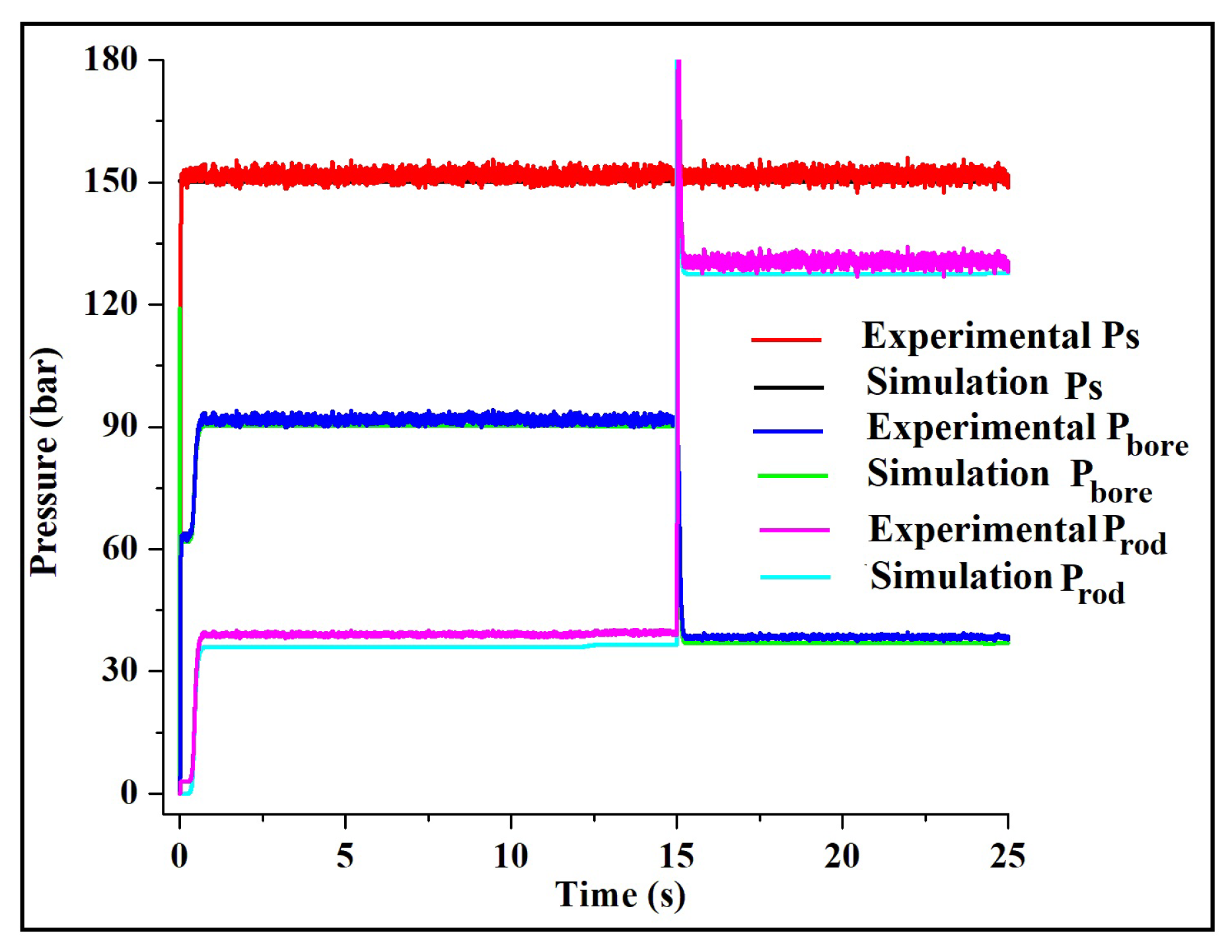
4.1.2. Pressure Across Different Lines
Pressure variation across different lines, i.e., supply line, bore side, and rod side corresponding to the position of the steering cylinder, is shown in Figure 7. The supply line (red color) pressure is always at the maximum set pressure of PRV, i.e.150 bar (approx.). Bore side pressure of the steering cylinder is shown in with the blue colored line, and rod side pressure is shown in pink color, respectively. The relative difference between simulation and experimental values of the pressures vary in the range of 2 -3 bar. Hence, the simulated model is closely matched with the experimental ones.
Figure 7.
Pressures across different hoses of the PDCV controlled steering system for the considered case.
Figure 7.
Pressures across different hoses of the PDCV controlled steering system for the considered case.
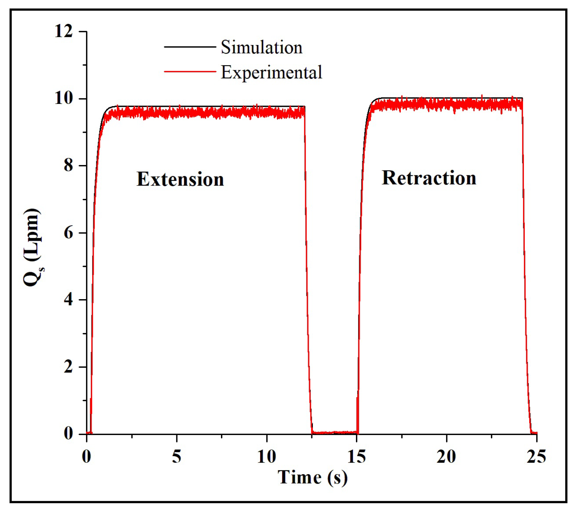
4.1.3. Flow Entering into the Steering Cylinder
Flow entering into the steering cylinder, i.e., bore side flow while extending and rod side flow while retraction of the steering cylinder is shown in Figure 8. At the dwell time, the flow is reduced to zero, a whole flow coming out of the hydraulic pump passes through PRV. From the comparative study, it is observed that the experimental values of the flow are slightly less compared to the simulation values. This is may be because of the unaccounted fluid flow losses while performing the experiments.
Figure 8.
Pressures across different hoses of the PDCV controlled steering system for the considered case.
Figure 8.
Pressures across different hoses of the PDCV controlled steering system for the considered case.
4.2. Validation of Orbitol Model
Different cases are considered by varying input frequency range (250Hz to 400Hz) and external load (15kN to 35kN) acting for the development of the simulation model. The results of the case with maximum input varying parameters (i.e., 400Hz and 35kN) are shown and discussed below.
4.2.1. Position of the Steering Cylinder
In the open-loop condition, the extension and retraction of the position of the steering cylinder using the orbitrol valve are shown in Figure 9. Simulation results closely match the experimental results with a maximum difference of 3% in response to the position of the steering cylinder.
4.2.2. Pressure Across Different Lines
Pressure variation across different lines, i.e., supply line, bore side, and rod side corresponding to the position of the steering cylinder, is shown in Figure 10. Unlike for the PDCV valve, the steering pressure in the supply line at the dwell time of the steering cylinder position is slightly above the atmospheric pressure. This is because there is no steering input in the dwell condition. As there is no steering input, the flow from the pump is directly diverted into the tank through the orbitrol valve. This is the significant difference provided by the orbitrol valve compared to PDCV. Supply line pressure bore side pressure and rod side pressures are indicated with red, blue, and magenta lines of color, respectively. A maximum difference of 3 bar pressure is observed from the comparative study between simulation and experimental results.
4.2.3. Flow Entering Into the Steering Cylinder
Flow entering into the steering cylinder, i.e., bore side flow while extending and rod side flow while retraction of the steering cylinder is shown in Figure 11. As earlier said, there is no steering input at the dwell time. Hence, there is no flow entering into the steering cylinder. From the figure, it can be observed that the simulation results are closely matching with the experimental values.
5. Comparison Analysis of PDCV and Orbitrol Valve
5.1. Estimation of the Demand Position
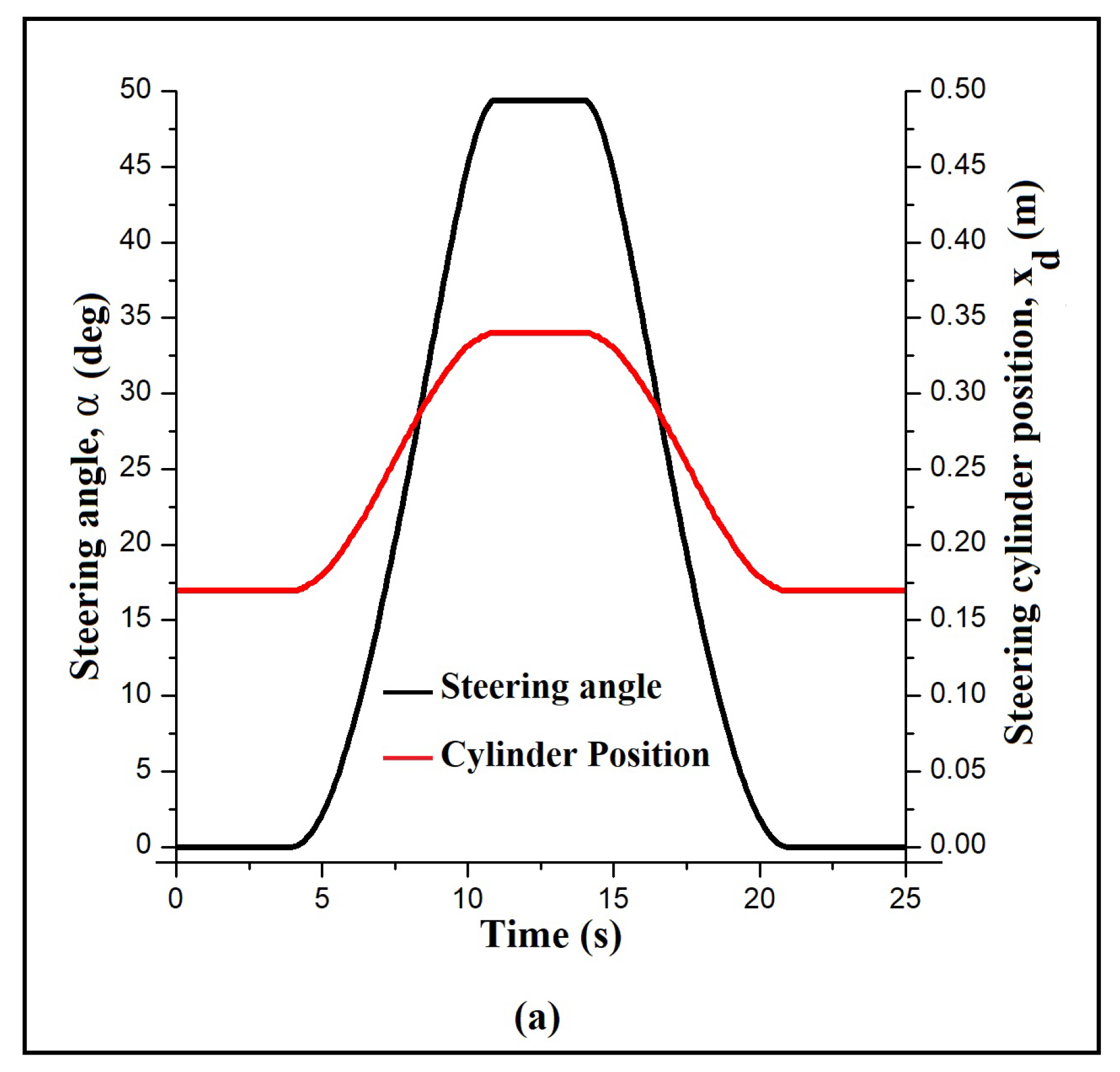
In the underground mines, the route splitting pattern is right-angled. To achieve the required steering by the vehicle operating in the constrained gallery of the underground mines, the steering angle must vary from 0 to ±450. Based on the path profile having a right-angle turn at the diversion, the desired profile of steering angle () and the demand position of steering cylinder are evaluated on MSC Adams 2019®, which is shown in Figure 1 (a).
The CAD model of the LHD machine is imported into the MSC ADAMS environment, and the steering command for the right angle turn is given to the machine. Based on the steering command, the position of the steering cylinder and the corresponding variation of the steering angle is obtained from the simulation results of the MSC ADAMS model.
Position control of the steering cylinder, pressure variation, and hydraulic power calculation for the operation of the steering system using both PDCV and Orbitrol valve are discussed in the following subsection.
Figure 12.
Steering angle and steering cylinder position profile vs. time.
5.2. Comparison Analysis
Considering the demand position discussed in Section 5, position control of the steering cylinder using both PDCV and Orbitrol valve is achieved. The performance, pressure variation, and power calculations are compared using the experimental results.
5.2.1. Step Response
For the step input of 0.3m steering cylinder position, the step responses of the PDCV system and SMDOV system for the extreme damping ratio values of the system has shown in Figure 13. The time constant for the step response of the PDCV system is 0.2547s and for the SMDOV steering system, is 0.4767s, respectively.
5.2.2. Comparison of Steering Cylinder Position
Demand position of the steering cylinder and the position tracking response using PDCV and orbitrol valve is shown in Figure 14 with black, green, and red color, respectively. From the comparative study, it is observed that position tracking results are more accurate using PDCV when compared with orbitrol valve response. The steering response of the PDCV is also higher than the orbitrol valve steering response. This is because of the difference in pressure across the valve. The higher the difference in pressure higher will be the steering response. Hence, overall, PDCV offers better tracking results and steering responses when compared to the orbitrol valve steering system.
5.2.3. Comparison of Supply Pressure and Working Pressure
For the considered position tracking control, the variation of pressure in the supply line and pressure working against the load is shown in Figure 15 (a) and (b), respectively. The supply pressure for PDCV is almost near 150bar irrespective of the situation whereas, the supply pressure for the orbitrol valve is 90bar and 110bar approximately for the cylinder extension and retraction case, respectively. By observing Figure 14 (b), the working pressures of the PDCV and orbitrol valve have a difference in the range of 10 to 15 bar for the full extension and retraction cycle.
5.2.4. Energy Comparison
Using the pressure and flow passing through the line, the energy required is calculated for the supply line and the working line, shown in Figure 16 (a) and (b), respectively. From Figure 16 (a), the area below the black color curve represents the energy consumed/required by the PDCV steering unit. The area inside the red color curve represents the energy consumed by the orbitrol valve steering unit for the same operation. Energy consumed by the PDCV supply pressure is 127.67kJ, while the orbitrol valve circuits consume 59.7kJ. The difference in energy which is 67kJ of energy can be saved by using the orbitrol valve steering system for the case considered, i.e., approximately 52% of energy can be reduced by operating with the orbitrol valve steering system.
From Figure 16 (b), it can be observed that energy consumed by the working line for the entire cycle of PDCV and orbitrol valve is 17.5 and 14.5, respectively. This means approximately 3kJ of energy is saved on the working side of the steering cylinder. From both the figures, it is evident that the orbitrol valve steering system proved to be the energy-efficient one compared to the PDCV steering system. In general, the differences between PDCV and orbitrol valve by considering different factors are mentioned in Table 1.
6. Discussion
Authors should discuss the results and how they can be interpreted from the perspective of previous studies and of the working hypotheses. The findings and their implications should be discussed in the broadest context possible. Future research directions may also be highlighted.
7. Conclusions and Future Scope
The present article is focused on the comparative analysis of PDCV and orbitrol steering valves with respect to response and energy efficiency factors. Mathematical modeling of the PDCV operated articulated steering systems PDCV and orbitrol valve-operated system is developed in MATLAB environment based on the experimental results. Demand position for the right angle turn is calculated using the ADAMS simulation model, and position control of the steering cylinder is achieved using conventional PID control for both the steering systems considered. The comparative results show that the PDCV controlled steering system’s response is 1.01s whereas, for the SMDOV system, the steering response is 1.9068s. While in the energy efficient aspect, the orbitrol valve steering system proved quite an efficient one compared to the PDCV steering system, which saves almost 50% of the energy consumed by the PDCV operated steering system. For the articulated off-road vehicles, the manual steering operation’s response time () lies in the range of 0.02 – 0.48s [21], which is quite possible with the orbitrol valve-operated articulated steering system. Hence, the orbitrol valve-operated articulated steering system proves to be quite an efficient one compared to the PDCV operated articulated steering system. Further to extend the current research topic, different hydraulic circuits can be developed so that pressure lines need to be always at the maximum set pressure of the system. For the orbitrol steering system, different mechanisms need to be developed for enhancing the steering response, and mechanisms need to be evolved to develop autonomous steering operations, which can be the potential future scope of work for the current article.
Author Contributions
“Conceptualization, A.K. and N.K.; methodology, S.R. and M.B.; software, S.R. and M.B.; validation, S.R.; formal analysis, S.R. and M.B.; investigation, S.R.; resources, N.K.; data curation, S.R. and M.B.; writing—original draft preparation, S.R.; writing—review and editing, S.R.,N.K., A.K. and M.B.; visualization, S.R.; supervision, N.K.; project administration, N.K.; funding acquisition, N.K. and A.K.. All authors have read and agreed to the published version of the manuscript.”, please turn to the CRediT taxonomy for the term explanation. Authorship must be limited to those who have contributed substantially to the work reported.
Funding
Our sincere gratitude should go to the Department of Science & Technology, Government of India, for financial support to the research project (Ref. No.-SR/FST/ET-I/2018/180)
Acknowledgments
In this section you can acknowledge any support given which is not covered by the author contribution or funding sections. This may include administrative and technical support, or donations in kind (e.g., materials used for experiments). Where GenAI has been used for purposes such as generating text, data, or graphics, or for study design, data collection, analysis, or interpretation of data, please add “During the preparation of this manuscript/study, the author(s) used [tool name, version information] for the purposes of [description of use]. The authors have reviewed and edited the output and take full responsibility for the content of this publication.”
Appendix A

Table A1.
Details of the sensors used for the proposed system.
| Type of the Sensors | Specific Details |
|---|---|
| Load Sensor | Load Range: 0 – 125 kN Output signal range: 0–10 V |
| Pressure Transducer | Pressure Range: 0–160 bar Output signal: 4–20 mA |
| Flow Sensor | Flow rate range: 0–30 Lpm Output signal: 4–20 mA |
| Linear Variable Differential Transformer (LVDT) | Output signal range: 0–5 V |
| Data Logger | HYDAC HMG 3000 model |
Table A2.
Details of the components used for the proposed system.
| Type of the Sensors | Specific Details |
|---|---|
| Power Pack (Electric Motor + Pump) | Angular speed of electric motor – 1000 rpm Displacement of the hydraulic pump – 20 cc/rev Volumetric Efficiency of the Pump – 0.92 |
| Orbitrol Valve | Displacement of the Valve – 200 cc/rev |
| Steering Cylinder | Bore diameter – 85 mm Rod diameter – 40 mm Stroke length – 340 mm |
| Viscous Loading Unit | Displacement of the Load pump – 12 cc/rev Angular speed – 1500 rpm |
| Load Cylinder | Bore diameter – 85 mm Rod diameter – 40 mm Stroke length – 340 mm |
| Hybrid Stepper Motor | Maximum torque – 9 N.m Step angle – 1.8 degrees |
| Flexible Hydraulic Hoses | Load-bearing Capacity – 250 bar |
Table A3.
System Parameters and Notations.
| Notation | Parameter | Value |
|---|---|---|
| – | Hydraulic Oil | ISO VG 68 |
| Fluid Density | 850 kg/m3 | |
| Bulk Modulus | N/m2 | |
| Coefficient of Discharge | 0.64 |
References
- Tørdal, S.S.; Klausen, A.; Bak, M.K. Experimental System Identification and Black Box Modeling of Hydraulic Directional Control Valve. Model. Identif. Control 2015, 36. [CrossRef]
- Ferrari, A.; Pizzo, P.; Rundo, M. Modelling and experimental studies on a proportional valve using an innovative dynamic flow-rate measurement in fluid power systems. Proc. Inst. Mech. Eng. Part C J. Mech. Eng. Sci. 2018, 232. [CrossRef]
- Liu, Y.F.; Dai, Z.K.; Xu, X.Y.; Tian, L. Multi-domain modeling and simulation of proportional solenoid valve. J. Cent. South Univ. Technol. (Engl. Ed. 2011, 18. [CrossRef]
- Quan, L.; Xu, X.; Yan, Z.; Zhang, X. A new kind of pilot controlled proportional direction valve with internal flow feedback. Chin. J. Mech. Eng. (Engl. Ed.) 2010, 23. [CrossRef]
- Ruderman, M. Full- and reduced-order model of hydraulic cylinder for motion control. In Proceedings of the Proceedings IECON 2017 - 43rd Annual Conference of the IEEE Industrial Electronics Society, 2017, Vol. 2017-January. [CrossRef]
- Zhu, Y.; Jin, B. Analysis and modeling of a proportional directional valve with nonlinear solenoid. J. Braz. Soc. Mech. Sci. Eng. 2016, 38. [CrossRef]
- Meng, F.; Tao, G.; Luo, P.P. Dynamic analysis of proportional solenoid for automatic transmission applications. In Proceedings of the 2014 International Conference on Mechatronics and Control, ICMC 2014, 2015. [CrossRef]
- Zhang, J.; Lu, Z.; Xu, B.; Su, Q. Investigation on the dynamic characteristics and control accuracy of a novel proportional directional valve with independently controlled pilot stage. ISA Trans. 2019, 93. [CrossRef]
- Xu, B.; Su, Q.; Zhang, J.; Lu, Z. Analysis and compensation for the cascade dead-zones in the proportional control valve. ISA Trans. 2017, 66. [CrossRef]
- Lee, I.Y.; Oh, D.H.; Ji, S.W.; Yun, S.N. Control of an overlap-Type proportional directional control valve using input shaping filter. In Proceedings of the Mechatronics, 2015, Vol. 29. [CrossRef]
- Dasgupta, K.; Ghoshal, S.K.; Kumar, S.; Das, J. Dynamic analysis of an open-loop proportional valve controlled hydrostatic drive. Proc. Inst. Mech. Eng. Part E J. Process Mech. Eng. 2019, 233. [CrossRef]
- Bo, H.; Liang, W.; Yuefeng, D.; Zhenghe, S.; Enrong, M.; Zhongxiang, Z. Design and Experiment on Integrated Proportional Control Valve of Automatic Steering System. 2018, Vol. 51. [CrossRef]
- Rösth, M. Hydraulic Power Steering System Design in Road Vehicles : Analysis, Testing and Enhanced Functionality. PhD thesis, Linköping UniversityLinköping University, Department of Management and Engineering, The Institute of Technology, 2007. The printed version and the electronic version differ in that the electronic version contains two built in video films (see page 78 and page 89).
- Zardin, B.; Borghi, M.; Gherardini, F.; Zanasi, N. Modelling and simulation of a hydrostatic steering system for agricultural tractors. Energies 2018, 11. [CrossRef]
- Silva, J.A.; Nacif, G.C.L.; Cabezas-Goméz, L. Continuous Improvements Analysis in Energy Efficiency of Steering Power Systems to Light Vehicles. Appl. Mech. Mater. 2015, 798. [CrossRef]
- Daher, N.; Ivantysynova, M. Energy analysis of an original steering technology that saves fuel and boosts efficiency. Energy Convers. Manag. 2014, 86. [CrossRef]
- Sreeharsha, R.; Kumar, N.; Kumar, A. Automatic control and stability analysis of a novel stepper motor-driven orbitrol valve operated articulated steering mechanism. J. Braz. Soc. Mech. Sci. Eng. 2024, 46, 375.
- Singh, V.P.; Olesen, E.N.; Pedersen, H.; Minav, T. Experimental evaluation of a novel electro-hydrostatic steering solution for off-road mobile machinery. Energy Convers. Manag. 2025, 332, 119710.
- Li, S.; Zhang, Z.; Du, H.; Zheng, G.; Zhang, X.; Li, Z. Design and verification of a novel energy-efficient pump-valve primary-auxiliary electro-hydraulic steering system for multi-axle heavy vehicles. Energy 2024, 312, 133473.
- Amoruso, F.; Cebon, D. Brake-actuated steering control strategy for turning of articulated vehicles. Veh. Syst. Dyn. 2025, 63, 424–454.
- Taheri, S. Steering Control Characteristics of Human Driver Coupled with an Articulated Commercial Vehicle. PhD thesis, Concordia University, 2014. Unpublished.
Figure 1.
Steering cylinder arrangement for an articulated vehicle (a) Neutral case, (b) When turned right side.
Figure 1.
Steering cylinder arrangement for an articulated vehicle (a) Neutral case, (b) When turned right side.
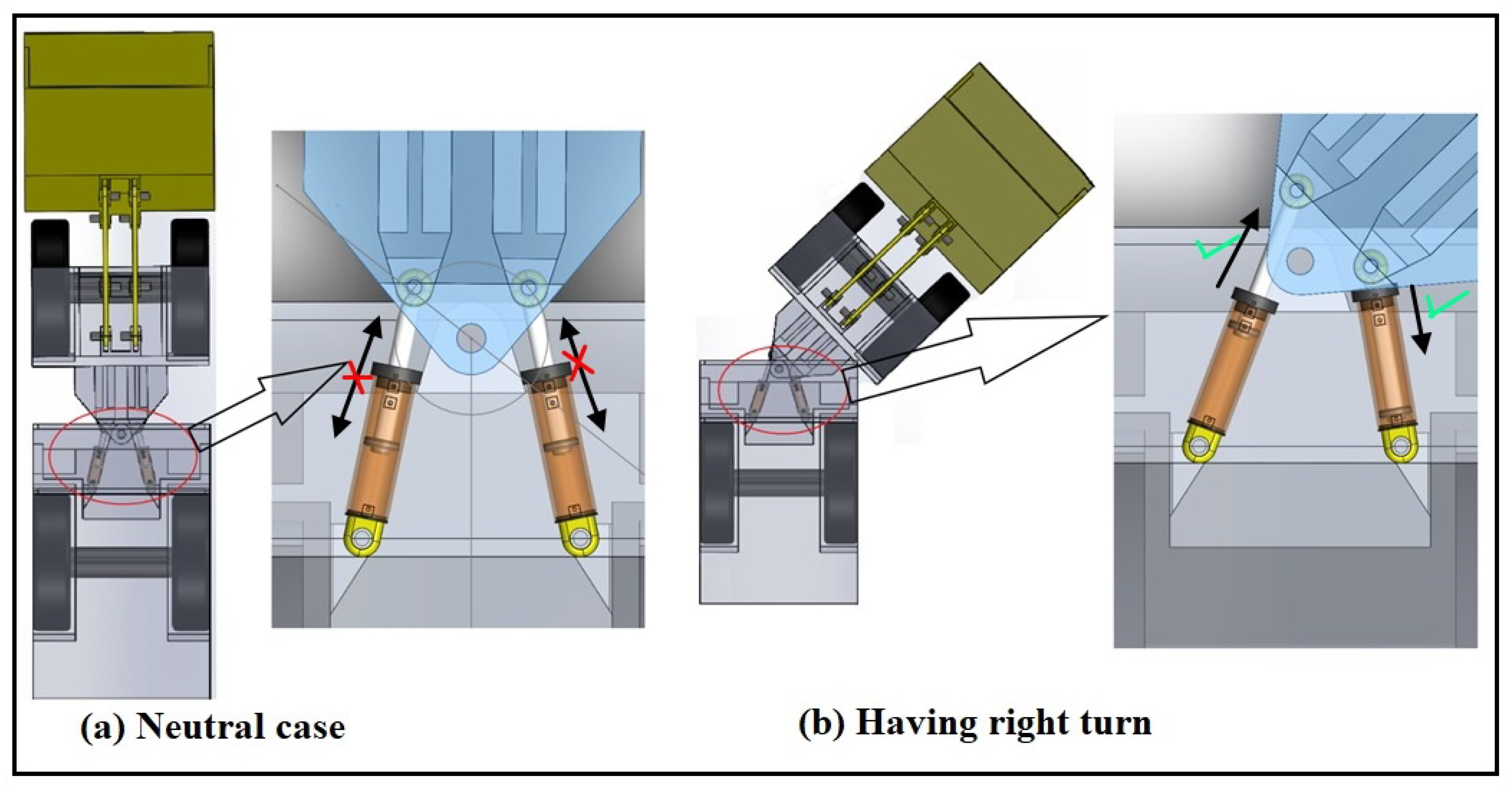
Figure 2.
Experimental test rig.
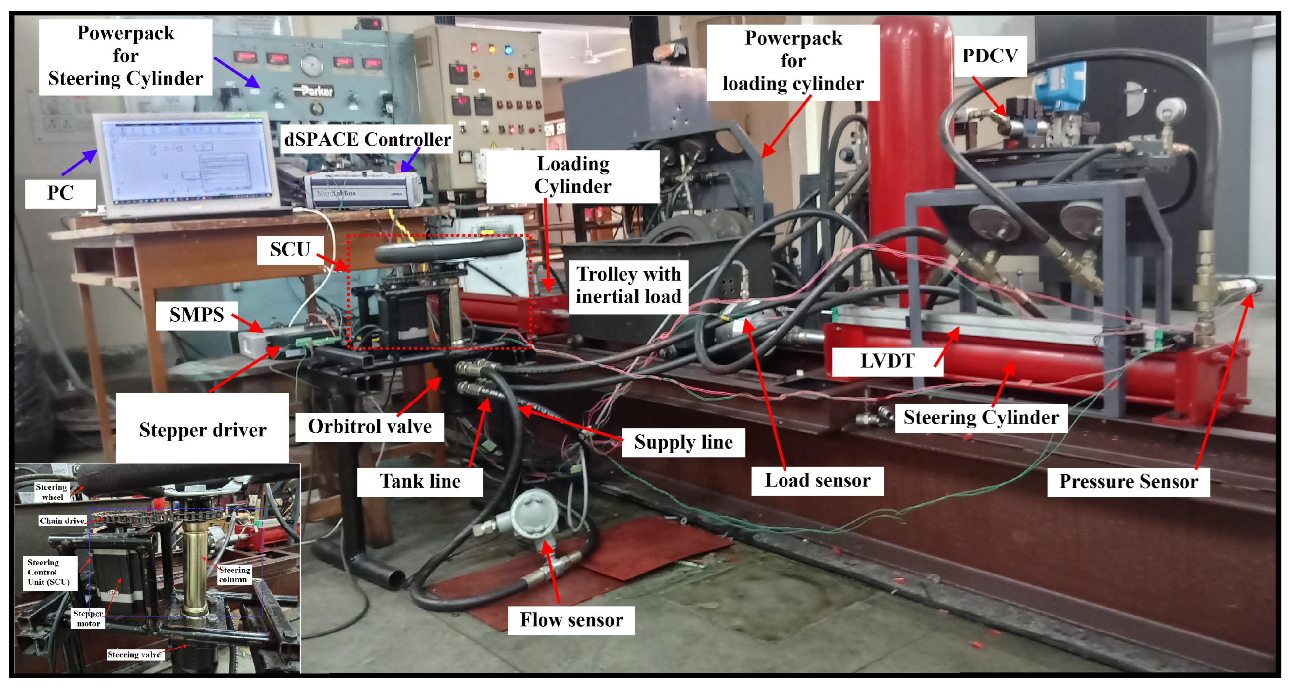
Figure 3.
Hydraulic circuit diagram of the experimental test rig.
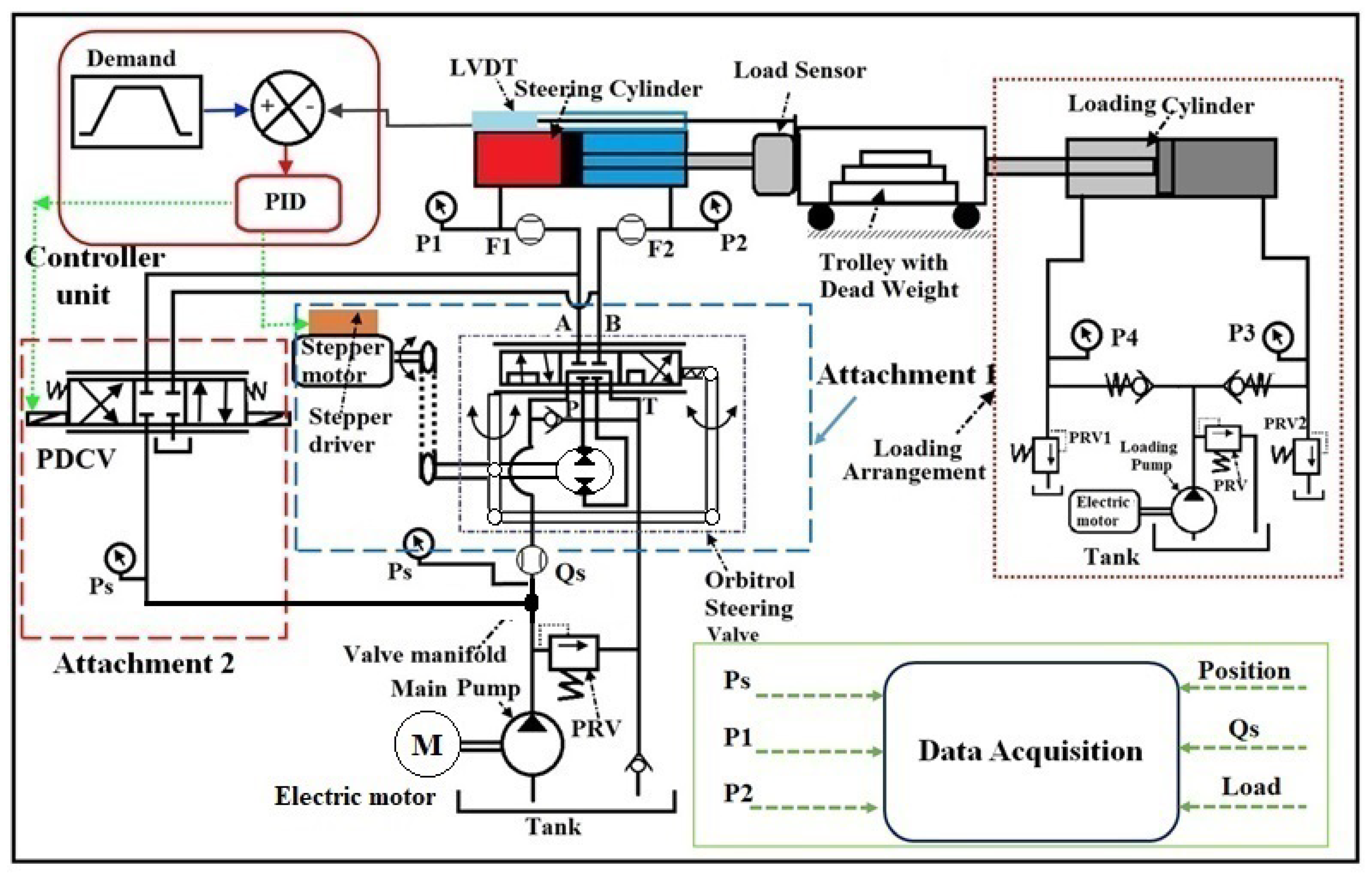
Figure 4.
Simulation model of the position control of the PDCV operated ASS.
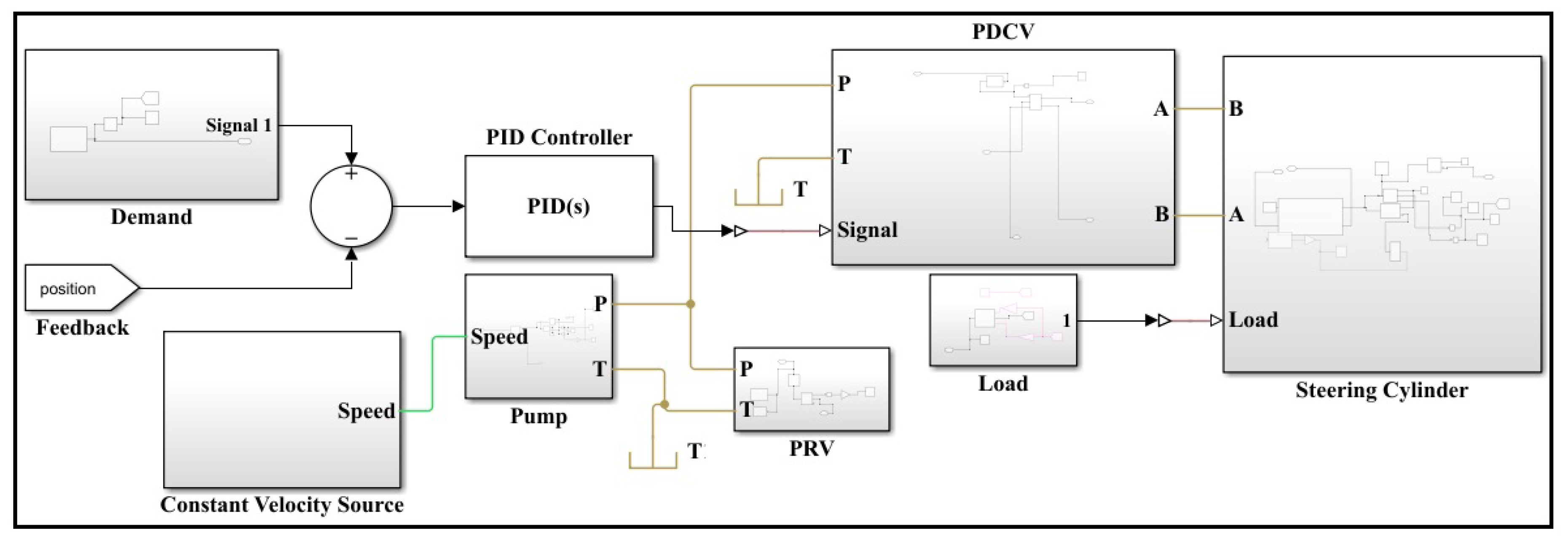
Figure 5.
Simulation model of position control of the SMDOV operated ASS.
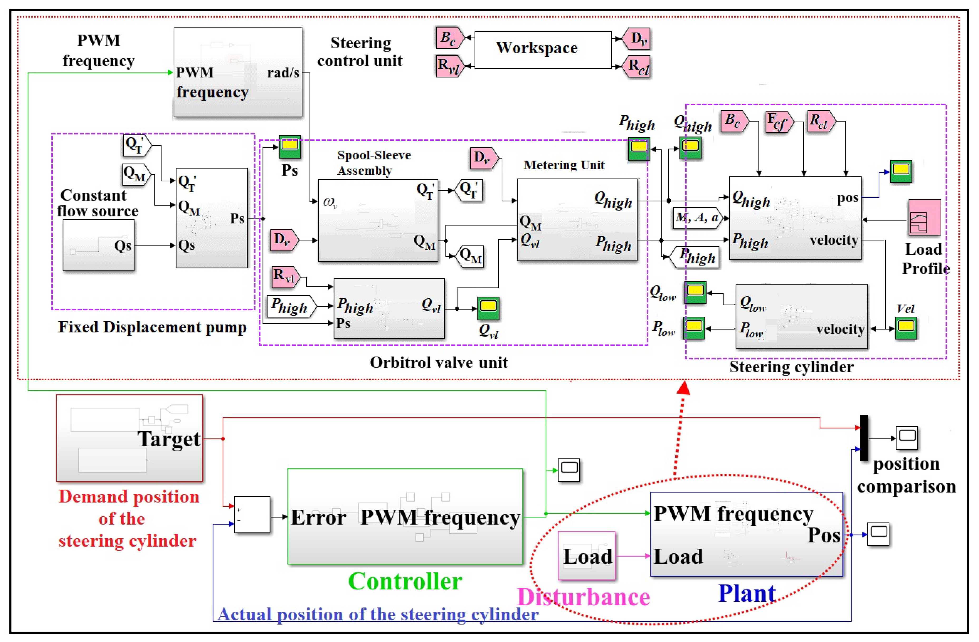
Figure 6.
Position of the steering cylinder controlled through PDCV in Open-loop condition.
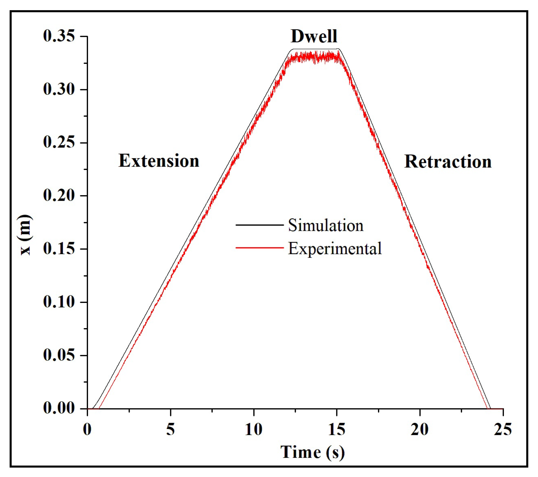
Figure 9.
Position of the steering cylinder operated using Orbitrol valve in Open-loop condition.
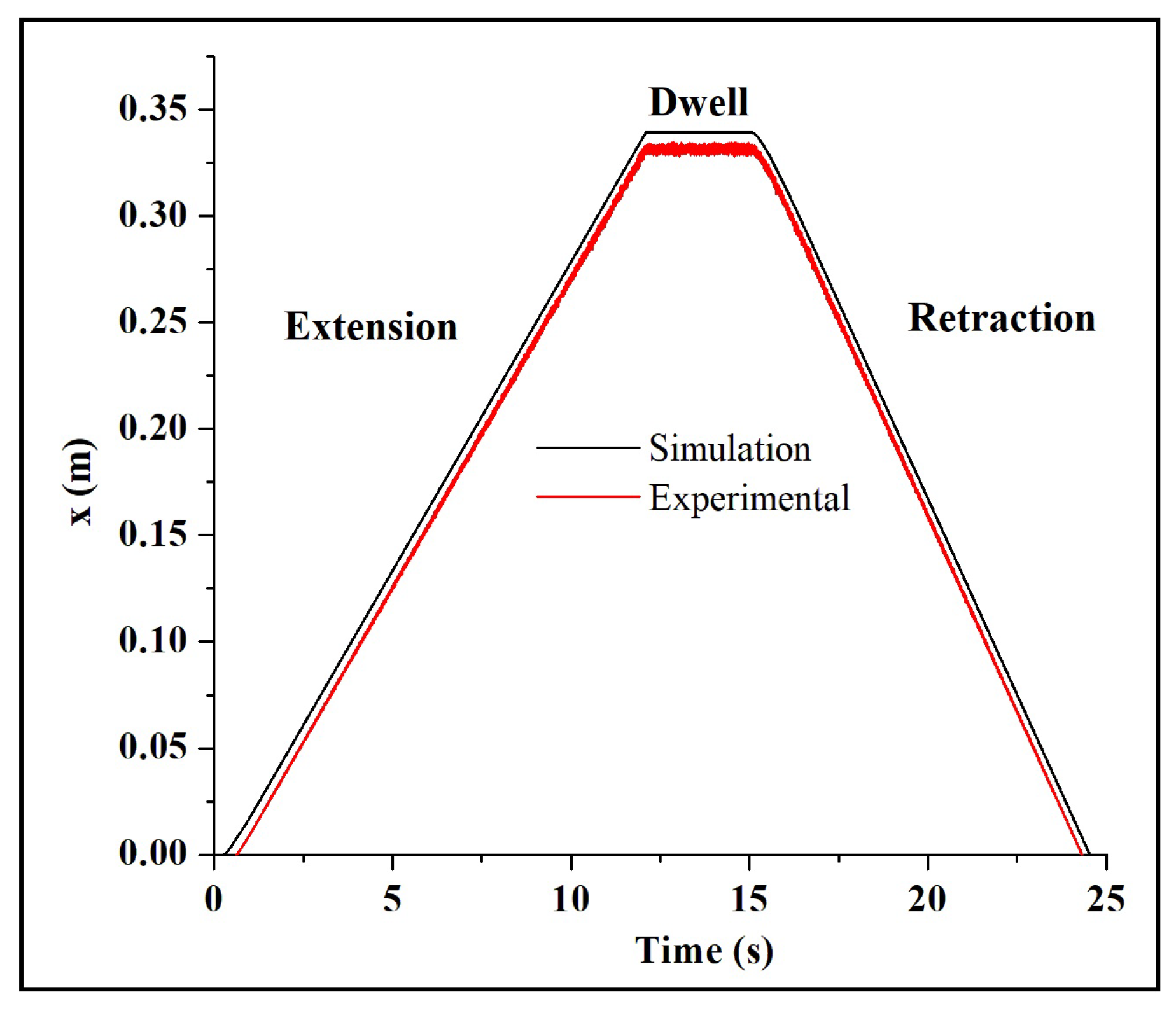
Figure 10.
Pressures across different orbitrol valve-controlled steering system hoses for the considered case.
Figure 10.
Pressures across different orbitrol valve-controlled steering system hoses for the considered case.
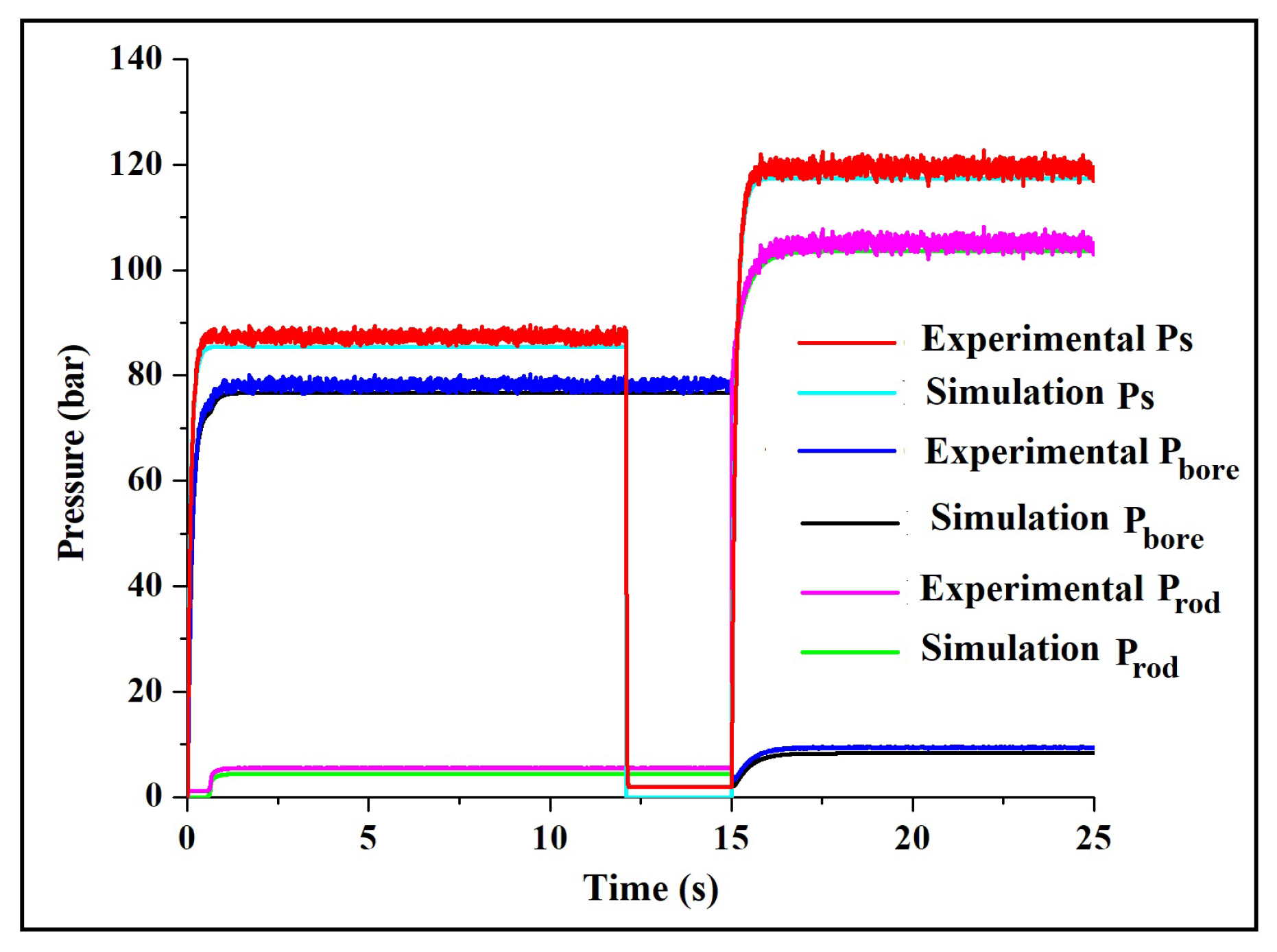
Figure 11.
Flow entering into the steering cylinder for the extension and retraction of the considered case.
Figure 11.
Flow entering into the steering cylinder for the extension and retraction of the considered case.
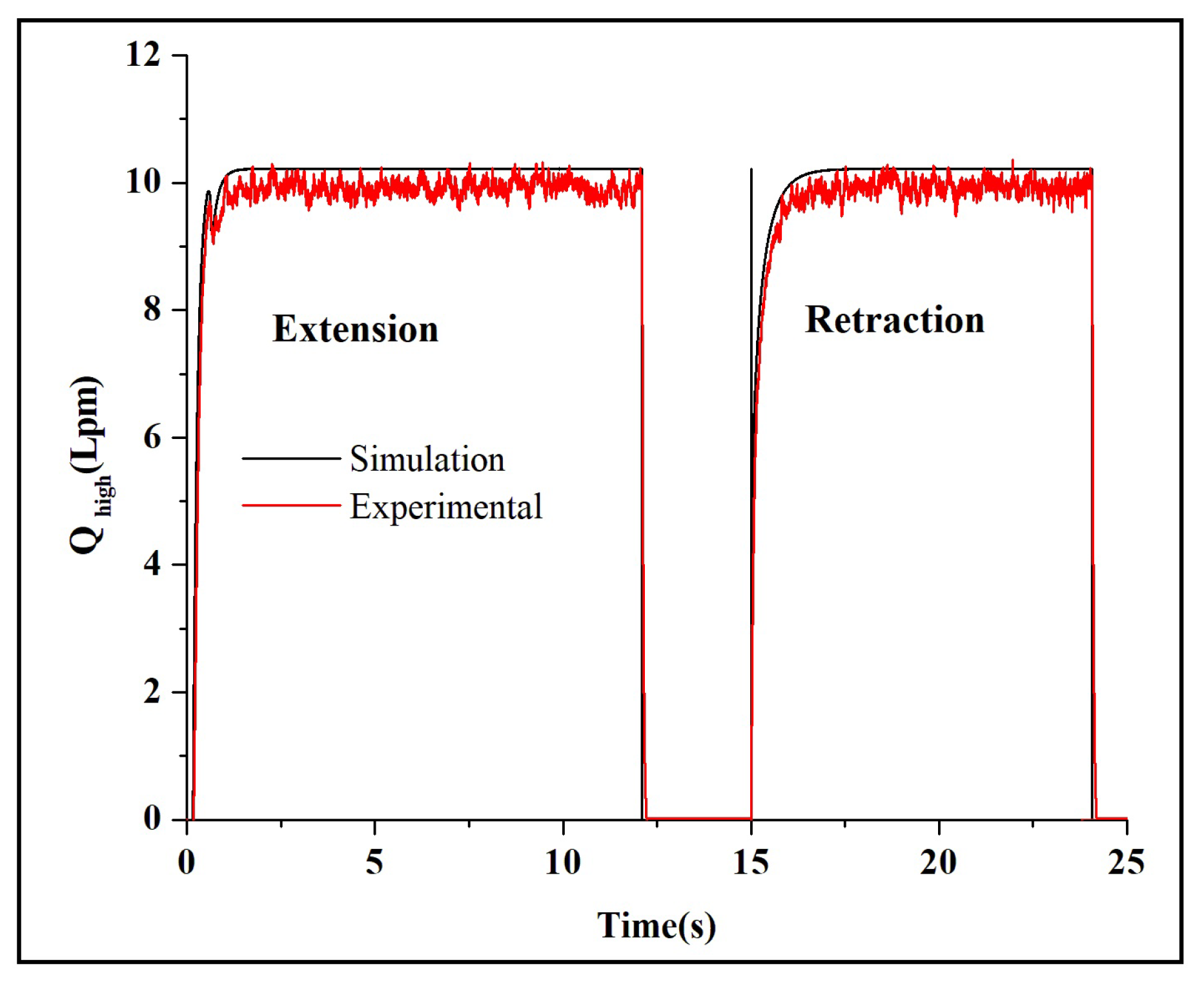
Figure 13.
Step response comparison of PDCV vs SMDOV steering system.
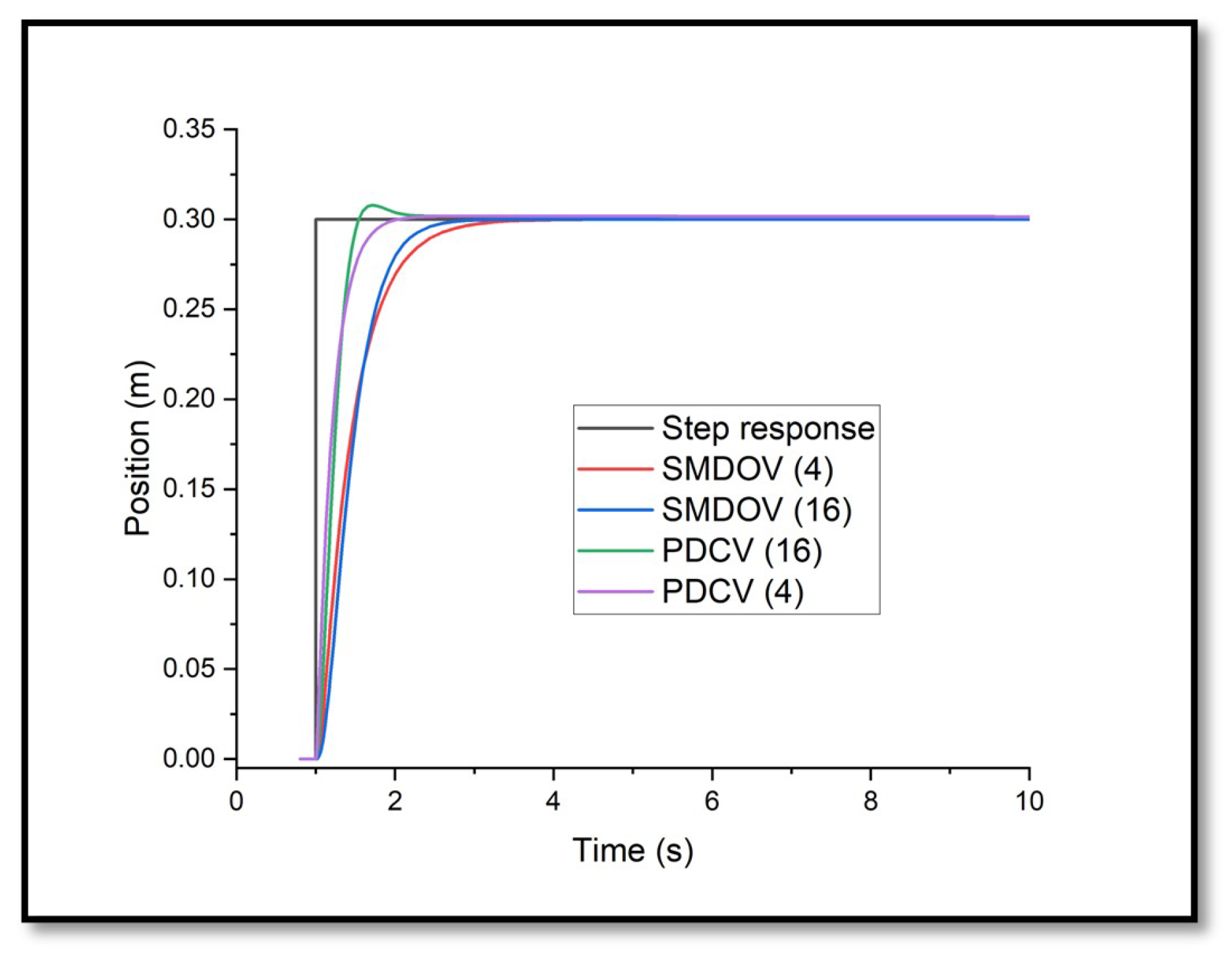
Figure 14.
Steering cylinder position comparison of PDCV and Orbitrol Valve.
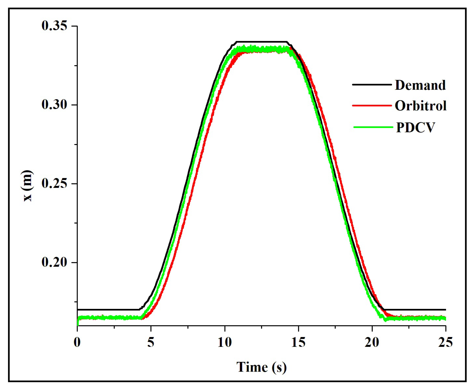
Figure 15.
Pressure variation of PDCV and Orbitrol valve (a) Supply Pressure;(b) working pressure(pressure against a load).
Figure 15.
Pressure variation of PDCV and Orbitrol valve (a) Supply Pressure;(b) working pressure(pressure against a load).
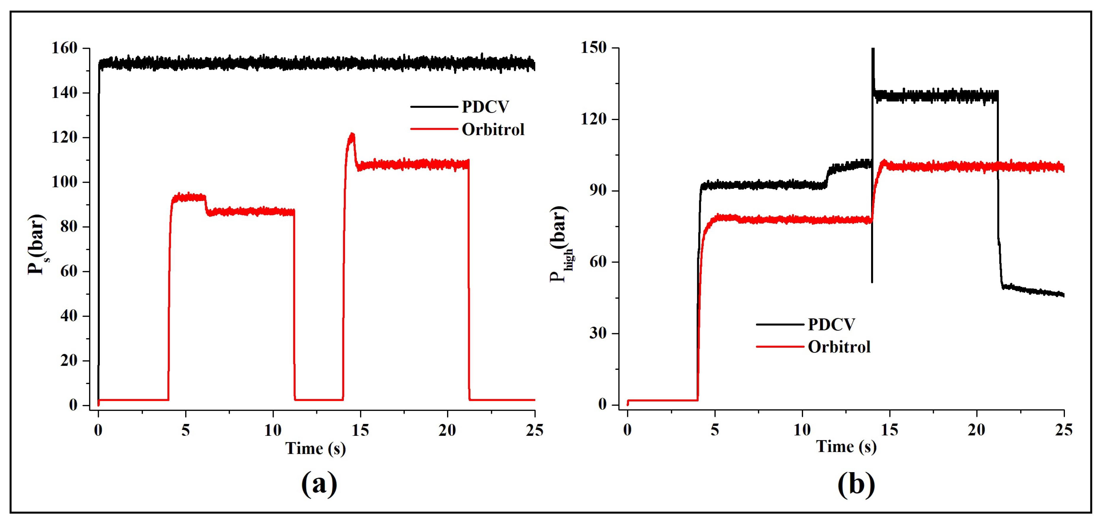
Figure 16.
Pressure variation of PDCV and Orbitrol valve (a) Supply Pressure;(b) working pressure(pressure against a load).
Figure 16.
Pressure variation of PDCV and Orbitrol valve (a) Supply Pressure;(b) working pressure(pressure against a load).
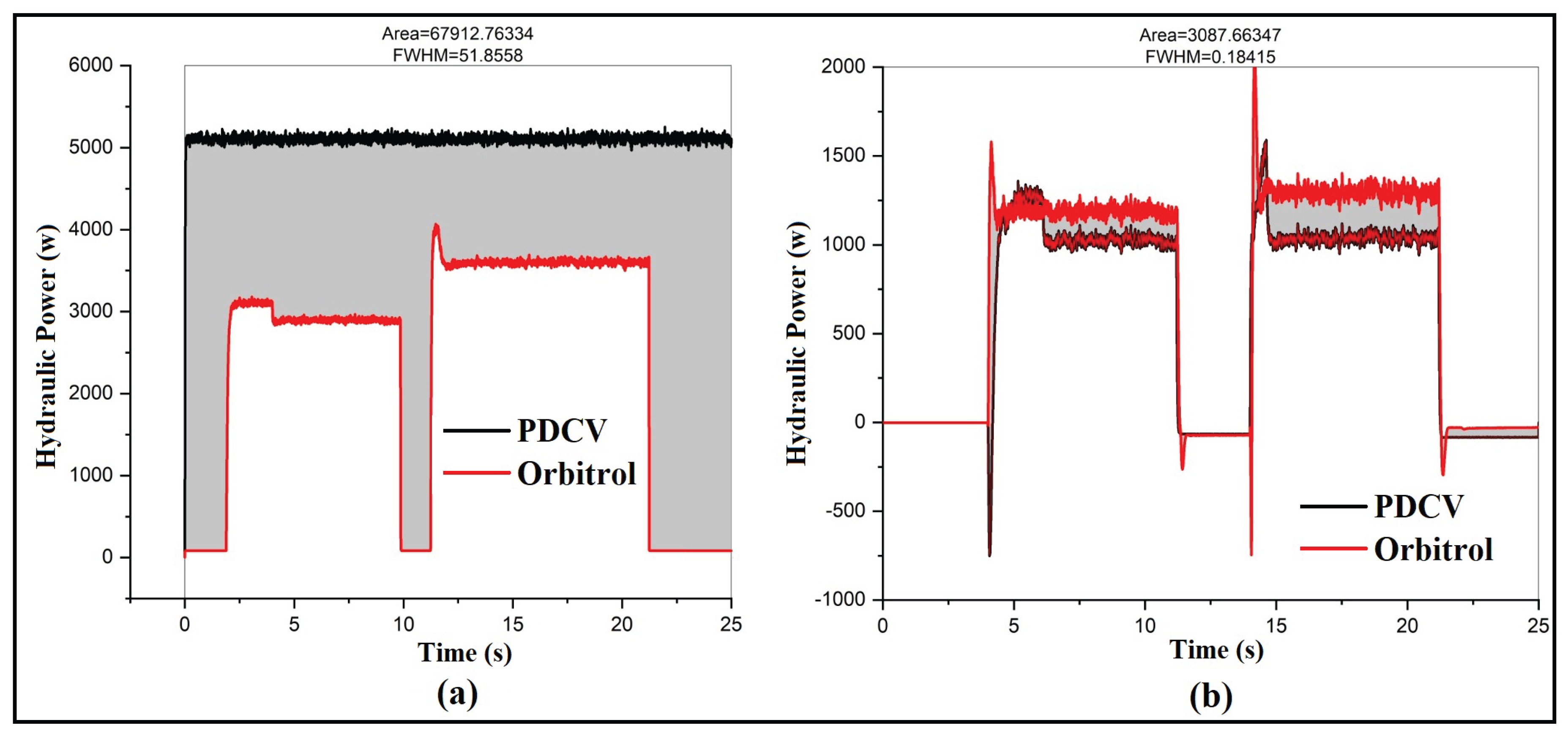
Table 1.
This is a table caption. Tables should be placed in the main text near to the first time they are cited.
Table 1.
This is a table caption. Tables should be placed in the main text near to the first time they are cited.
| Factors | PDCV | SMDOV |
|---|---|---|
| Steering Response | As the valve operates at high-pressure differences, the response of the valve is also relatively higher | Do not have a high response but enough for articulated steering purposes |
| Energy Efficient | Pressure losses are high. So, not an energy-efficient one | Pressure losses only when there is steering input, and it also provides a tandem sort of arrangement when there is no steering input. Hence, it saves a lot of energy and is an efficient one |
| Cost | Quite High | Not Costlier |
| Ease of usage | Easy for automation applications | Not easy for the automation of the steering system |
| Design | Relatively less complex | Design is quite complex |
| Mode of Operation | It is operated by supplying a voltage source of ±12V | Manual Operated using Steering Wheel |
Disclaimer/Publisher’s Note: The statements, opinions and data contained in all publications are solely those of the individual author(s) and contributor(s) and not of MDPI and/or the editor(s). MDPI and/or the editor(s) disclaim responsibility for any injury to people or property resulting from any ideas, methods, instructions or products referred to in the content. |
© 2025 by the authors. Licensee MDPI, Basel, Switzerland. This article is an open access article distributed under the terms and conditions of the Creative Commons Attribution (CC BY) license (http://creativecommons.org/licenses/by/4.0/).
Copyright: This open access article is published under a Creative Commons CC BY 4.0 license, which permit the free download, distribution, and reuse, provided that the author and preprint are cited in any reuse.


