Submitted:
03 July 2025
Posted:
04 July 2025
You are already at the latest version
Abstract
Magnetic gears (MGs) are attracting increasing attention in power transmission systems due to their contactless operation principles, low frictional losses, and high efficiency. However, the broad application potential of these technologies requires a comprehensive evaluation of engineering parameters such as material selection, energy efficiency, and structural design. This review systematically examines the topological diversity, torque transmission principles, and the impact of various core materials such as electrical steels, soft magnetic composites (SMCs), and cobalt-based alloys on the performance of magnetic gear systems. Literature-based comparative analyses are structured around topological classifications, evaluation of material properties, and performance analyses based on losses. Additionally, the study highlights that aligning material properties with appropriate manufacturing methods such as powder metallurgy, wire electrical discharge machining (EDM), and precision casting is essential for the practical scalability of magnetic gear systems. The findings reveal that coaxial magnetic gears (CMGs) offer a favorable balance between high torque density and compactness, while soft magnetic composites provide significant advantages in loss reduction, particularly at high frequencies. Additionally, application trends in fields such as renewable energy, electric vehicles (EVs), aerospace, and robotics are highlighted.
Keywords:
magnetic gears
; torque density
; magnetic materials
; topological structures
; flux modulation
; manufacturability
; material process compatibility
1. Introduction
Magnetic gears (MGs) have emerged as a robust alternative to conventional mechanical systems due to their contactless torque transmission, low maintenance requirements, and silent operation advantages [1,2]. Their high efficiency and structural durability in key parameters such as power, torque, and speed transmission make them particularly attractive for compact design applications [3]. However, the saturation limits of the magnetic materials used impose physical constraints on the torque density achievable in such systems. The development of Neodymium Iron Boron (NdFeB) magnets in the 1980s marked a significant milestone in the evolution of magnetic gear technology, enabling solutions that are not only highly energy-dense but also more cost-effective [4]. Studies in the literature have shown that increasing the number of pole pairs positively affects torque transmission capacity [3,5,6].
Magnetic gears are increasingly applied in advanced engineering fields such as aerospace, renewable energy systems, electric transportation, and space technologies [7,8,9,10,11,12,13,14]. Nonetheless, their relatively low torque density and certain geometric limitations compared to classical mechanical gears remain key barriers to broader industrial adoption. In this context, recent research efforts have increasingly focused on novel design strategies and material-oriented optimizations aimed at enhancing torque performance [15,16].
In magnetic gears, torque is transmitted without physical contact through the modulation of magnetic fields generated by permanent magnets. This principle not only eliminates mechanical wear but also enhances reliability in dynamic applications [17,18]. Critical parameters such as the air gap between rotors, the number of poles, and pole alignment directly influence overall system performance. Particularly in flux-modulated structures, ferromagnetic elements placed between rotors guide magnetic flux paths, thereby enabling effective torque transmission [19,20].
This study aims to provide a comprehensive review of recent advances in magnetic gear systems, evaluating their topological diversity, torque transmission principles, material selection, and performance outcomes. While some research focuses directly on improving key performance indicators such as torque density, losses, and efficiency, others explore the design of new topologies tailored to specific applications, material optimization, and thermal analysis.
The primary objective of this work is to examine the structural and magnetic parameters that influence the engineering design of magnetic gear systems from a holistic perspective. The study also compares various methodologies adopted in the literature and identifies prominent research gaps driving the field forward. Furthermore, the magnetic, thermal, and mechanical properties of core materials and their impacts on system performance are addressed in detail.
In the following sections, magnetic gear classification and operating principles, along with the performance characteristics of modulated and non-modulated topologies, design parameters, thermal behavior, core material manufacturability, and their comparative impacts on system performance are addressed; finally, current application potentials and future research and design strategies are discussed.
2. Literature Review and Methodology
In this study, the increasing scientific interest in magnetic gear systems is examined through a structured analytical process from both thematic and methodological perspectives.
During the literature review, a comprehensive search was conducted using major academic databases such as Google Scholar, IEEE Xplore, ScienceDirect, Web of Science, and Scopus. The search employed keywords and logical combinations including “magnetic gear,” “coaxial magnetic gear,” “flux modulation gear,” “magnetic gear torque density,” “magnetic losses,” and “magnetic gear material comparison.” Although the review focused primarily on studies published after the year 2000, earlier foundational research works were also included. The scope of the review encompasses original research articles, review papers, and publications involving experimental and numerical analyses.
The collected literature was categorized under four main thematic areas based on content-oriented analysis. The first category addresses topological diversity, analyzing modulated and non-modulated magnetic gear structures, magnet and rotor configurations, and carrier geometry design parameters. The second category focuses on material-based evaluations, comparing the magnetic and thermal characteristics of core materials such as electrical steels, soft magnetic composites (SMCs), and cobalt-based high performance steels. Additionally, the suitability of these core materials for manufacturing methods such as machining, wire EDM, investment (precision) casting, and powder metallurgy was evaluated in terms of surface machinability, tolerance to geometric complexity, and impact on production precision, providing a more comprehensive analysis of their applicability in magnetic gear systems. The third section discusses performance and loss analysis, with particular attention to volumetric torque density (VTD), core and solid losses, and overall system efficiency. Finally, the fourth category reviews application-oriented studies, evaluating the implementation potential and operational advantages of magnetic gear systems in various engineering domains including renewable energy, electric vehicles, robotics, aerospace, and marine technologies.
3. Topological Diversity and Structural Design in Magnetic Gear Systems
Magnetic gear systems can be developed with various topological structures and designs depending on their intended function and operating conditions. The performance of these systems is influenced by multiple parameters, including the configuration of the rotors, the arrangement of the magnets, and the geometry of the carrier structure. In general, a magnetic gear consists of an inner rotor, a carrier (also referred to as a modulator), and an outer rotor. While the permanent magnets on the inner and outer rotors are expected to generate high magnetic flux density, the size and geometry of the ferromagnetic segments located on the carrier directly affect the torque transmission capability.
The air gap between the rotors and the alignment of magnetic poles are among the primary factors that determine torque ripple and system losses. Based on their structural characteristics, magnetic gears are commonly categorized into two main groups: conventional (non-modulated) types and modulated types. Each of these categories includes several sub-topologies, which are illustrated in Figure 1.
3.1. Conventional Non-Modulated Magnetic Gear
Non-modulated magnetic gears (MGs) represent one of the most fundamental structural types in magnetic torque transmission. In these systems, the input and output rotors interact magnetically through directly opposing arrays of permanent magnets; there is no additional ferromagnetic modulator to direct or modulate the magnetic field. This simplified structure not only reduces design complexity but also lowers manufacturing costs. Torque transmission occurs through the alignment of magnetic poles on the rotors and the direct interaction of the magnetic fields. The number of poles on the input and output rotors is typically equal or configured according to a specific ratio; however, this limits the flexibility of the gear ratio. Additionally, due to the restricted magnetic flux paths, the torque density is generally lower compared to modulated structures. The torque capacity of these systems is directly related to rotor dimensions and the magnetic properties of the permanent magnets used such as remanent flux density (Br), coercivity (Hc), maximum energy product (BHmax), and temperature resistance. Therefore, while they are not preferred in applications requiring high torque, they are commonly used in low-power and low-speed applications due to their simplicity and cost advantages. Non-modulated magnetic gears are further divided into different sub-topologies based on magnet orientation, placement geometry, and torque transmission mechanism. Figure 2 structurally illustrates eight fundamental topologies frequently encountered in the literature.
Figure 2a illustrates the Spur-type magnetic gear, which features the simplest structure among conventional magnetic gears. It is configured similarly to mechanical gears, but it transmits power through the face-to-face arrangement of permanent magnets rather than physical contact. This design minimizes drawbacks such as wear, friction, and the need for lubrication [21]. In Figure 2b, the Worm-type magnetic gear is shown, consisting of a helically magnetized rotor that magnetically interacts with a mating gear. Its ability to achieve high gear ratios without contact makes it attractive for robotics and precision control applications [22]. Figure 2c presents the Perpendicular magnetic gear, which generates radial magnetic field interaction through magnets aligned orthogonally to one another. Its compact size and 1:1 rotation ratio enable high efficiency in confined spaces [23]. Figure 2d shows the Magnetic Screw gear, characterized by a helical magnet arrangement that converts rotary motion into linear motion or vice versa without physical contact. Its quiet operation and lack of lubrication requirements make it ideal for use in sensitive or sterile environments [24]. The Planetary-type magnetic gear, shown in Figure 2e, is designed as a non-contact counterpart of the classic planetary system. It consists of sun, planet, and ring rotors, which interact synchronously through permanent magnets. Its key advantages include high torque density and multi-stage torque transmission [25]. The Cycloidal-type magnetic gear in Figure 2f operates based on the non-contact magnetic interaction between a cycloidal disc with curved magnet poles and fixed pin structures. This configuration is particularly suitable for defense and aerospace applications requiring high gear ratios and torque density [26,27]. The Harmonic magnetic gear, shown in Figure 2g, includes three main components: a wave generator, a flexspline, and a circular spline. Torque transmission is achieved through the periodic variation of the air gap enabled by elliptical magnet arrangements. This topology is notable in the literature for its ability to provide high speed ratios and torque density [28,29]. Finally, Figure 2h illustrates the Trans-Rotary magnetic gear, which transforms rotational motion into linear motion through helical magnet arrays on the rotor and linear components. System performance is directly influenced by alignment, helix angle, and air gap parameters [30].
These topologies offer various advantages depending on the application area. Their ability to transmit torque without contact, low maintenance needs, wear-free operation, and quiet functioning make them strong alternatives to conventional gear systems. Numerous studies in the literature [21,22,23,24,25,26,27,28] emphasize their high torque density and long operational life, highlighting their significance in modern engineering applications that require precision and reliability.
3.2. Modulated Magnetic Gear
With the development of high-energy permanent magnets (PMs) and the increasing use of advanced magnetic circuit designs, modulated magnetic gears (MGs) have emerged as a powerful alternative, particularly in linear and rotary systems requiring high torque density and efficiency [31,32]. The key feature of the modulated design is the incorporation of ferromagnetic modulators placed between the input and output rotors. These modulators reshape the magnetic flux lines, guiding the magnetic path and thereby enhancing the system's torque transmission capability. Furthermore, the involvement of all magnets in active torque production significantly improves magnetic utilization efficiency. This design approach offers ideal solutions for applications demanding high torque density and wide gear ratio ranges.
Figure 3 presents structural representations of eight fundamental modulated magnetic gear topologies commonly discussed in the literature. These topologies exhibit different performance characteristics depending on the modulator arrangement, magnet configuration, and system geometry.
Figure 3a presents the coaxial magnetic gear, composed of three main components: an inner rotor, an outer rotor, and a stationary modulator ring. The permanent magnet arrangements on the inner and outer rotors are synchronized through the modulator to enable torque transmission. This configuration has been further developed in various forms such as surface-mounted variants and dual-stack coaxial arrangements to enhance torque density and mechanical stability. The spoke-type magnetic gear (Figure 3b) employs internal permanent magnet (IPM) structures to reduce eddy current losses within the magnets. The rotor’s integration with cage-like steel poles improves torque density while offering an alternative to the manufacturing complexities of surface-mounted configurations [33,34]. Figure 3c shows the IPM-type magnetic gear, which includes two counter-rotating rotors and fixed stator pole pieces. Based on the internal permanent magnet concept, this structure eliminates the need for magnet holders in high-speed applications, offering structural advantages [35]. The reluctance-type magnetic gear (Figure 3d) features permanent magnets only on the low-speed rotor, with the high-speed rotor comprising solely of salient iron structures. Operating on the vernier principle, this design enables torque transmission even without permanent magnets, providing a unique solution [36,37]. The L-shaped axial-flux magnetic gear (Figure 3e) uses L-shaped ferromagnetic pole pieces to reduce flux leakage and improve torque density. However, due to its inherently complex three-dimensional structure, it presents significant manufacturing challenges [22,38]. The T-shaped axial magnetic gear (Figure 3f) maximizes torque production by employing both axial and transverse magnetic paths. T-shaped soft magnetic components reduce saturation and minimize flux leakage, thereby enhancing system efficiency [39]. Figure 3g illustrates the hybrid-flux magnetic gear, which features a triple permanent magnet excitation (TPME) topology combining both transverse and axial flux paths. Iron segments enable both magnetic flux modulation and additional torque generation, resulting in higher torque capacity compared to traditional designs [40]. Finally, the HTS linear magnetic gear (Figure 3h) utilizes high-temperature superconducting (HTS) bulks for flux modulation. The Meissner effect significantly reduces flux leakage while boosting linear torque output. This topology shows great promise for precision applications requiring linear motion [41].
These advanced modulated magnetic gear topologies, with their innovative structural features and high-performance potential, are poised to play a key role in future applications particularly in electric drive systems, robotic mechanisms, and compact mechanical transmission solutions.
3.3. Operating Principles and Theoretical Fundamentals of Magnetic Gear
This section examines the fundamental operating principles, design parameters, torque transmission losses, and efficiency analyses of magnetic gear systems. Additionally, current research on proposed design approaches and cooling strategies in the literature is discussed, with emphasis on their impact on system performance. In magnetic gears, torque transfer is achieved through the interaction of opposing magnetic fields generated between the rotors. As the permanent magnets on one rotor rotate, they exert magnetic attraction or repulsion forces on the other rotor, resulting in a magnetic coupling. This mechanism creates a variation in magnetic flux density when one rotor remains stationary and the other rotates, enabling torque transmission.
The system’s maximum torque limit is defined by Tmax. If this limit is exceeded, magnetic slip occurs between the rotors, causing the intended gear ratio to be compromised. Therefore, ensuring that the operating load remains below this threshold is of critical importance during the design phase [42,43]. Figure 4 schematically illustrates the torque transmission mechanism in a typical magnetic gear system.
3.4. Design Parameters of Magnetic Gears
Geometric characteristics play a crucial role in determining the gear ratio and torque performance of magnetic gears (MGs). Similar to mechanical gear systems, the gear ratio in MGs defines the relationship between the input and output speeds. However, instead of using the number of mechanical teeth, MGs utilize the number of magnetic pole pairs [44]. To better understand the structural differences and torque transmission principles between mechanical and magnetic gears, Figure 5 presents a comparative illustration of the typical configurations of both systems.
In a magnetic gear, the number of magnets on the inner rotor is denoted by nPM−in, and the number of magnets on the outer rotor is denoted by nPM−out. The number of modulators on the carrier is given by:
As shown in Figure 6, the gear ratio varies depending on the selected fixing strategy. For a magnetic gear with 14 outer magnets, 6 inner magnets, and 10 modulators on the carrier, the gear ratio is observed to change as follows: when the modulator ring is fixed, gr = 7 / 3; when the outer rotor is fixed, gr = 10 / 3; and when the inner rotor is fixed, gr = 10 / 7. As seen, the highest gear ratio is achieved when the outer rotor is fixed, making this configuration particularly suitable for low-speed and high-torque applications. Depending on which component is fixed, both the gear ratio and torque transmission vary, enabling optimization according to the specific design objectives of the system. Emerging geometrical variations such as conical coaxial magnetic gears offer unique design advantages, particularly for axial space-constrained environments, although they introduce new challenges in flux modulation and mechanical alignment [48]. In addition to gear ratio optimization, the magnet arrangement and selection of magnet material must be carefully considered to enhance system efficiency and torque output.
The Halbach array, commonly used in magnetic gear systems, increases the magnetic flux density in the air gap by arranging magnets with a specific magnetization pattern, while simultaneously minimizing leakage flux on the yoke side. Figure 7 illustrates a typical Halbach magnet arrangement and the resulting magnetic flux distribution.
In a study presented in the literature, magnetic field profiles in the air gap obtained through finite element analysis demonstrated that the use of a Halbach array in an outer rotor magnetic gear significantly enhances the magnetic focusing effect. Comparative analysis revealed that, following modulation, magnetic peaks aligned with the pole pairs formed on both the inner and outer rotors [49]. Particularly in the outer rotor design with the Halbach configuration, magnetic flux steering capabilities were markedly improved, which led to an overall enhancement in the system’s torque performance [50,51].
The effectiveness of such arrangements, which enhance magnetic field concentration, is directly related to the appropriate selection of magnet materials. In magnetic gear systems, not only the type of arrangement but also the physical and magnetic properties of the magnets used are critical to improving efficiency.
Among magnets produced from rare earth elements, Neodymium-Iron-Boron (NdFeB) magnets offer the highest energy density and residual magnetic induction after Samarium-Cobalt (SmCo) alloys. NdFeB magnets are preferred in high-performance applications due to their high energy density and magnetic flux values per unit volume [52]. However, their primary disadvantages are their relatively low Curie temperatures and high cost [53]. A comparative summary of the advantages and disadvantages of NdFeB magnets versus other types such as Alnico and SmCo is provided in Table 1.
As shown in Table 1, NdFeB magnets stand out with their high energy density advantage; however, due to their low Curie temperature, they have limitations in high-temperature applications. The performance of permanent magnets is generally defined by their energy density, which is expressed as the maximum energy product (BHmax). These advantages and disadvantages serve as important references for guiding magnet selection based on the intended application. In particular, the low Curie temperature of NdFeB magnets should be carefully considered in high-temperature applications. Table 2 presents a comparative overview of the magnetic properties of different types of permanent magnets.
As seen in Table 2, NdFeB magnets stand out with their high BHmax values and strong remanent magnetic induction, whereas SmCo magnets are notable for their high-temperature resistance and superior coercive force. These comparisons play a critical role in magnetic material selection, as they directly impact overall system performance. However, beyond material properties, design optimizations also play a decisive role in determining performance parameters such as torque density.
Therefore, the following section will address the concept of torque density in magnetic gears and present studies aimed at its enhancement. Various design optimization efforts have been conducted to increase the volumetric torque density in magnetic gear systems. For example, using a slotted magnetic modulation ring in the carrier structure has led to improvements in static torque performance. Figure 8 illustrates the structure of a coaxial magnetic gear (CMG) with a slotted modulation ring.
In a study conducted using finite element analysis (FEA), the ratio of permanent magnet pole pairs was set at 1:4.25, and the static torque was found to increase by approximately 4–4.12% compared to conventional coaxial magnetic gears (CMGs). Furthermore, torque ripple was reduced by 72.28% and 69.84%, while iron loss and eddy current loss decreased by 8.91% and 66.57%, respectively [55]. These design improvements aimed at increasing torque density offer significant opportunities for enhancing the mechanical performance of magnetic gear systems. However, thermal effects also represent a critical aspect of the design, just as important as mechanical parameters in ensuring long-term system reliability. In this context, the following section examines the thermal behavior and thermal management strategies in magnetic gear systems in detail.
Thermal effects in magnetic gear systems become a critical engineering consideration, especially in compact designs targeting high torque density. As system dimensions increase and the air gap between the input and output rotors narrows, the surface area available for convection decreases. This leads to increased thermal resistance and complicates effective system cooling. The thermal load generated by core losses and eddy currents becomes more pronounced under such conditions. In particular, the high electrical conductivity of permanent magnet materials significantly increases eddy current losses, leading to severe heating. Literature shows that with increasing rotational speed, these losses and the resulting system temperature also rise [56,57]. This temperature increase may cause thermal deformation in components and degradation of magnetic materials, thus threatening system reliability. For example, in a magnetic gear system designed for integration into a 6 MW wind turbine operating at 12.5 rpm, analyses showed that the heat generated from magnetic losses could be effectively managed using an axial airflow cooling system [58]. In this study, magnetic losses were calculated through analytical modeling, while heat transfer was analyzed using a thermal network model and the finite element method (FEM). A more recent study conducted mutual heat transfer analysis using 3D flow and conduction/convection methods in a fully laminated magnetic gear system. The average outer rotor temperature was estimated with an error 2.5 K lower than that obtained using a simple conduction model [59].
Eddy currents in magnetic gear systems are a significant source of heat, primarily due to the high electrical conductivity of permanent magnet materials. Analytical and semi-analytical models have been developed to predict these losses in related rotating machines such as permanent magnet synchronous machines [60] and induction motors [61], providing valuable insights into their behavior under various operating conditions. It is well-known that with increasing rotational speed, both eddy current and core losses intensify, leading to elevated temperatures and reduced system efficiency [56,57,62]. To mitigate eddy current formation in magnets, design strategies such as axial and circumferential segmentation are commonly employed. Additionally, core losses are another important factor affecting system efficiency. In a study using the modified Steinmetz equation, core losses were analyzed considering the influence of harmonics, and high accuracy was achieved when compared to FEM results [63]. Lastly, in a study investigating different modulator structures with solid and laminated outer rotor materials, the impact of structural configurations on magnetic torque and efficiency was explored. The circumferentially laminated modulator design showed the lowest efficiency but was reported to offer simpler manufacturing advantages [64].
These findings demonstrate that magnetic gear systems must be optimized not only in terms of torque density and efficiency but also in terms of thermal management. This ensures enhanced performance as well as long-term operational reliability.
4. Comparative Evaluation of Magnetic Gear Core Materials
4.1. Evaluation Criteria and Normalization Method
In this study, different magnetic core materials were comparatively evaluated based on eight fundamental performance criteria. These criteria include saturation flux density, relative permeability, core loss, electrical conductivity, thermal conductivity, density, manufacturability, and cost. Since these criteria are expressed in different physical units, they were normalized to a 0–100 scale to enable a comparable analysis. First, a scaling approach was adopted for certain low-magnitude criteria (e.g., relative permeability, electrical conductivity, and density) to enhance visibility in radar chart representation. The applied scaling factors are clearly indicated in the figure caption. Second, all criteria were normalized to a 0–100 scale based on their functional impact. For performance-enhancing criteria (e.g., saturation flux density, magnetic permeability, thermal conductivity, manufacturability), direct normalization was performed using Equation (3). For parameters that negatively affect performance (e.g., core loss, cost, electrical conductivity, and density), inverse normalization was applied using Equation (4).
4.2. Technical Specifications and Numerical Comparisons
4.2.1. Material Properties
In the literature, the performance of magnetic gear systems employing different pole piece materials has been compared, and it has been demonstrated that material selection has a direct impact on torque density particularly in transverse flux magnetic gears. Studies have shown that soft magnetic composite (SMC) materials, due to their isotropic magnetic structure and high electrical resistivity, enable more effective 3D magnetic flux guidance in transverse flux magnetic gears. As a result, low-loss and compact designs with higher torque density can be achieved [65].
The technical specifications related to the performance of different magnetic core materials are summarized in Table 3. In this table, the fundamental parameters of electrical steel (M400 50A), soft magnetic composite (Somaloy 700HR 5P), and cobalt-based steel (Vacodur 50A) are systematically compared. The material data were compiled based on literature and experimental sources.
4.2.2. Manufacturability Assessment of Core Materials
In this section, the manufacturability of selected core materials is systematically evaluated with respect to material properties, applicable production techniques, and expected production volumes. The analysis focuses on three widely used magnetic core materials: M400 50A electrical steel, Somaloy 700HR 5P soft magnetic composite, and Vacodur 50A cobalt steel. Each material is assessed across four primary manufacturing methods: conventional machining, wire electrical discharge machining (EDM), investment casting, and powder metallurgy. Furthermore, both low volume prototyping and mass production scenarios are considered, given their significant impact on process feasibility and economic viability. The evaluation aims to identify the most practical manufacturing routes for each material by taking into account factors such as process compatibility, tooling requirements, production cost, and scalability.
- Machining
M400-50A electrical steel, with moderate hardness (~200 HV) and excellent ductility, offers acceptable machinability using standard HSS or carbide tools. Although its silicon content slightly increases tool wear, it is widely used in both prototyping and industrial manufacturing environments with minimal process complications [67]. The machinability index for M400-series steels typically ranges between 50–65 when normalized against free-machining steels[68]. This makes it highly suitable for low-volume prototyping, as parts can be rapidly machined with minimal investment. For mass production, however, conventional machining becomes less attractive due to longer cycle times compared to press-based or cast alternatives, although CNC-based automation can partially compensate.
Vacodur 50A, a Fe-Co alloy with exceptional magnetic saturation (~2.35 T), is considerably more difficult to machine. Its high hardness (~350 HV) and abrasive behavior cause accelerated tool wear, necessitating CBN or PCD tooling under low cutting speeds (20–30 m/min). These constraints significantly increase the cost and duration of part fabrication [69]. While technically feasible for low-volume prototypes, Vacodur’s poor machinability renders it unsuitable for conventional high-speed machining in mass production unless supported by specialized tooling, optimized parameters, and possibly grinding-based finishing processes.
Somaloy 700HR 5P, as a bonded soft magnetic composite, is inherently not suitable for conventional machining. Its brittle microstructure, composed of insulated iron particles and organic binders, tends to fracture or delaminate under cutting loads[70]. Although specially formulated machinable SMC grades (e.g., Hoganas SPM) exist for limited prototyping, these do not fully replicate the magnetic performance of pressed components. Therefore, machining is discouraged for both prototyping and mass production, especially when material integrity is critical.
- Wire EDM
Wire EDM is an effective method for producing precise geometries in hard-to-machine metals, particularly in prototyping stages. Vacodur 50A and M400-50A are both compatible with this technique and allow high-precision contouring without inducing mechanical stress. Due to these characteristics, EDM represents a suitable manufacturing method for low-volume, high-precision applications where sharp features and tight tolerances are required. However, EDM is inherently slow and energy-intensive, making it unsuitable for mass production. Furthermore, localized thermal effects during processing may alter the magnetic surface properties, requiring post-process annealing to restore magnetic permeability [71].
In contrast, Somaloy 700HR 5P is unsuitable for EDM. The process degrades the surface insulation layer and induces localized carbonization of the binder, leading to severe deterioration in magnetic and mechanical integrity [72]. As a result, EDM must be strictly avoided for both prototyping and production of SMC parts.
- Investment (Precision) Casting
Investment casting offers a route for producing near-net-shape components with complex outer geometries. While rarely used for magnetic cores, it is theoretically applicable to both M400-50A and Vacodur 50A, provided that the casting process is precisely controlled. Vacodur 50A, due to its high cobalt content and low fluidity, presents challenges such as segregation and internal shrinkage porosity unless performed under vacuum or inert atmosphere. Furthermore, post-casting vacuum annealing is essential to activate its magnetic properties [73]. While casting can enable mass production of complex shapes, the high cost of mold fabrication renders it uneconomical for single-part prototyping.
M400-50A is less favorable for casting due to its high silicon content, which increases the risk of hot cracking and reduces castability. Nonetheless, small and simple geometries may be cast for low-volume production if controlled cooling and alloy modifications are applied [74]. Despite its feasibility for simple geometries, casting is not considered cost-effective or time-efficient for prototyping applications.
Somaloy 700HR 5P, being a powder-bonded material, is entirely incompatible with casting. Its composition lacks the metallurgical continuity needed for melt processing, and thus, investment casting is not an option at any production volume.
- Powder Metallurgy
Somaloy 700HR 5P is specifically engineered for powder metallurgical production and provides significant advantages for mass manufacturing. It supports single-step pressing of net or near-net shapes with minimal material waste. Additionally, its isotropic magnetic behavior and high resistivity allow for 3D magnetic flux conduction without lamination, especially advantageous in complex coaxial or transverse magnetic topologies [75]. However, the initial investment in high-tonnage presses and precision molds is substantial, making this technique economically infeasible for prototyping or very low-volume production. In such cases, pre-machinable SMC blanks may be used with caveats on performance fidelity.
M400-50A and Vacodur 50A are not commonly processed via powder metallurgy, primarily due to poor compactibility and the need for high-temperature sintering atmospheres. While Fe-Co alloy powders can be produced, their cost and sintering complexity limit their use to niche experimental setups [76]. Therefore, powder metallurgy is not considered viable for either prototyping or mass production with these two materials under standard industrial conditions.
Following the detailed evaluations presented above, Table 4 provides a normalized manufacturability scoring of each core material across four major production methods and two production volume scenarios. M400-50A achieves the highest overall feasibility score (59/100) due to its balanced compatibility with machining, wire EDM, powder metallurgy, and casting. Somaloy 700HR 5P performs exceptionally well in mass production powder metallurgy (90/100), but its poor suitability for prototyping lowers its average score to 22/100. Vacodur 50A, while feasible for prototyping via EDM or precision machining, demonstrates limited scalability and high processing difficulty, resulting in a moderate manufacturability score of 36/100. These findings clearly highlight the importance of aligning material selection not only with physical properties but also with the chosen manufacturing method and expected production volume in magnetic gear system design.
The manufacturability of magnetic gear components is critically influenced by the selection of core materials, production methods, and intended production volumes. This review highlights that while traditional electrical steels like M400-50A offer balanced compatibility across multiple fabrication techniques, advanced materials such as Somaloy 700HR 5P and Vacodur 50A present trade-offs between performance and manufacturability. Somaloy 700HR 5P demonstrates excellent manufacturability in high-volume powder metallurgy applications, although its applicability in prototyping remains limited due to process-specific constraints. Vacodur 50A offers superior magnetic performance, but this comes at the expense of complex manufacturing requirements and high processing costs. These insights emphasize the need for early-stage manufacturability assessments in magnetic gear design, where material-process-volume alignment can significantly impact both technical feasibility and economic viability. Future advancements in additive manufacturing and hybrid processing may help mitigate current limitations, especially for materials with otherwise restricted formability. Figure 9 illustrates the comparative radar chart representations for each core material, where subfigures (a), (b), and (c) respectively highlight the normalized performance profiles of M400-50A, Somaloy 700HR 5P, and Vacodur 50A.
The normalized data were compared using a radar chart to enable multidimensional performance evaluation of different materials. As illustrated in the radar chart, Vacodur 50A demonstrates high performance particularly in saturation flux density (2.35 T), relative permeability (10,000), and electrical conductivity (2.38×10⁷ S/m). These parameters make Vacodur 50A especially suitable for applications requiring high magnetic density and rapid magnetic flux response. However, due to its high electrical conductivity, Vacodur 50A may suffer significant eddy current losses when used in bulk form under varying magnetic fields. Therefore, it is recommended to apply fine laminations when using this material in such systems. With proper lamination, these losses can be reduced to a tolerable level while maintaining high magnetic performance. On the downside, Vacodur 50A’s high cost and processing difficulties are limiting factors for widespread industrial use.
M400 50 A electrical steel offers a more balanced profile, providing moderate saturation flux density (2.10 T) and high manufacturability (90/100). When evaluated from a cost-performance perspective, it emerges as a suitable candidate for mass production-focused industrial applications. However, due to its high electrical conductivity, it may also experience elevated eddy current losses in variable magnetic field environments unless laminated [77].
Somaloy 700HR 5P, on the other hand, offers significant advantages in low core loss, low density, and ease of production in complex 3D geometries through powder metallurgy. Although it exhibits lower values in relative permeability and magnetic saturation parameters, its extremely low electrical conductivity (≈10⁻⁴ S/m) enables manufacturing in solid form. This feature allows the creation of low-loss structures without lamination, particularly in applications exposed to varying magnetic fields where eddy current losses must be avoided. Thus, SMC materials offer strategic advantages for transverse flux machines, magnetic gears, and compact 3D magnetic circuits. In summary, the radar chart reveals that Vacodur 50A is well-suited for high-performance, specialized applications; M400 50A is ideal for general industrial use; and Somaloy 700HR 5P is preferred for niche applications requiring low losses and flexible production capabilities. The multidimensional comparisons based on the radar chart provide crucial insights into the general performance profiles of the materials. However, to further deepen this evaluation, it is essential to analyze the fundamental magnetic characteristics of these materials. For this purpose, the B-H characteristic curves and permeability curves of the materials are presented and discussed below. Figure 10 illustrates the B-H characteristics of M400-50A, Somaloy 700HR 5P, and Vacodur 50. These curves reveal the materials’ tendencies to reach magnetic saturation flux density (Bs) and their magnetic permeability behavior. Vacodur 50 achieves the highest saturation level at 2.35 T, offering a significant advantage in applications requiring high magnetic flux density. Although Somaloy 700HR 5P exhibits a relatively lower saturation level, it stands out due to its low core loss characteristics. Studies on the performance of materials used in magnetic gear systems have particularly compared SMC and steel-based core materials. Experimental and numerical analyses have shown that SMC cores are effective at low frequencies and that SMC materials exhibit approximately 22% lower core losses than conventional electrical steels under high-frequency operation [56,78,79,80,81].
Figure 11 presents the magnetic permeability curves of the same materials. These curves reflect the permeability behavior of the materials under varying magnetic field conditions. M400-50A exhibits a higher initial permeability at low magnetic field levels, while Vacodur 50 displays a broader permeability profile across a wide range of magnetic fields. Somaloy 700HR 5P, on the other hand, offers more limited permeability at low field levels but provides advantages in terms of low core loss and lightweight characteristics.
Following the analysis of magnetic characteristics, the variation of core losses with frequency another critical parameter affecting material performance has been examined. Below, a comparative presentation of frequency-dependent core losses for M400-50A, Somaloy 700HR 5P, and Vacodur 50 materials is provided.
As seen in Figure 12, the M400-50A material exhibits the highest core loss values with increasing frequency. Somaloy 700HR 5P and Vacodur 50 show similar loss profiles in the low-frequency range, whereas Vacodur 50 demonstrates more stable performance at higher frequencies. Notably, at 400 Hz, the core loss of Vacodur 50 is approximately 30% lower than that of M400-50A. These results indicate that Vacodur 50 may be a more efficient choice for high-frequency applications. When selecting materials, not only magnetic characteristics but also factors such as density, core loss, and manufacturing cost must be considered. In this context, Somaloy (a soft magnetic composite) stands out in magnetic gear systems due to its low magnetic losses and high electrical resistivity. Vacodur alloys, on the other hand, are preferred for high energy density and efficiency focused applications due to their high saturation flux density (2.35 T) and low iron losses [83,84,85,86,87]. In this study, Vacodur 50A was used in laminated form, which contributes to the suppression of eddy current losses at high operating frequencies. Meanwhile, M400 50A electrical steel finds wide application in electromechanical systems thanks to its high permeability and low core loss [83,85,86]. Although SMC materials offer advantages with their low density and resistance to eddy current losses, they may experience increased saturation effects and thus higher iron losses in certain geometries due to their relatively low relative permeability when used in block form [62,65]. The analysis of these fundamental characteristics is consistent with the general trends observed in the radar chart. Vacodur 50A stands out in terms of performance with its high saturation flux density, superior conductivity, and stable permeability profile. M400 50A electrical steel offers a more balanced profile, while Somaloy 700HR 5P provides advantages in specific niche applications due to its light weight and low core loss.
In conclusion, material selection is not solely limited to magnetic performance criteria. Multidimensional parameters such as thermal conductivity, core loss, material density, and manufacturing costs must also be considered. In particular, the use of hybrid materials such as SMC-steel combinations or Vacodur steel composite solutions will play a significant role in optimizing the performance of magnetic gear systems in the future. In this regard, material-based improvements in magnetic gear systems should be approached with an interdisciplinary perspective, as this is a critical requirement for increasing system efficiency and torque density.
5. Application Areas
The primary function of electromechanical systems is the effective and controlled transmission of energy. Although structural variations exist depending on the application field, torque density often emerges as a critical performance indicator in these systems. Magnetic gear systems, with their contactless torque transmission structures, are considered a significant solution particularly in scenarios where reducing friction-related losses and minimizing maintenance requirements are essential. Recent reviews emphasize the expanding role of magnetic gears in mechanical power transmission, especially in sectors like transportation and robotics, where high reliability and low maintenance are critical [88].
Table 4 systematically summarizes different magnetic gear topologies, types of core materials used, gear ratios, volumetric torque densities, and manufacturability indices. These attributes directly influence the performance criteria of magnetic gear systems and stand out as critical parameters when selecting suitable systems for specific application areas.

Table 4.
Summary of Magnetic Gear Topologies, Core Materials, and Application Area.
| MG Topology | Material Type | GR | VTD | Application Area | Fig.Num. | Ref. |
|---|---|---|---|---|---|---|
| Linear MG | Steel 1010- M400 NdFeB |
3.25:1 | 1.7 MN/m³ | Electric Vehicles | Figure 3h | [89] |
| Axial MG | Silicon Iron NdFeB |
5.75:1 | 70 kN/m³ | Aerospace | Figure 3e and 3f | [90] |
| Spoke Ferrite MG | Steel 1018 NdFeB N40H |
4.25:1 | 84.4 kNm/m³ | Robotic Systems | Figure 3b | [81] |
| Cycloidal MG | Steel 1018 NdFeB |
22:1 | 141.9 kNm/m³ | Robotic Systems | Figure 2f | [91] |
| Spoke-Type Coaxial MG | Steel 1018 NdFeB |
5.5:1 | 92 kNm/m³ | Renewable Energy | Figure 3b | [33] |
| Surface-Mounted Coaxial MG | Steel 1018 NdFeB |
5.5:1 | 98.1 kNm/m³ | Robotic Systems | Figure 3c | [90] |
| Transverse Flux MG | Steel 416 Ferrite - NdFeB |
3.75:1 | 80.6 kNm/m³ | Electric Vehicles | Figure 2h | [92] |
| Concentric-Type MG | Steel M 19 NdFeB 35 |
10.5:1 | 100 kNm/m³ | Electric Vehicles | Figure 3g | [93] |
| Spoke Coaxial MG | Steel M 19 NdFeB |
5.75:1 | 162 kNm/m³ | Electric Vehicles | Figure 3b | [94] |
| Cycloidal MG | Steel M 19 NdFeB 42 |
33:1 | 300 kNm/m³ | Robotic Systems | Figure 2f | [95] |
| Dual-Stack Coaxial MG | Steel M 19- M27 NdFeB 50 |
7.67:1 | 221 kNm/m³ | Aerospace | Figure 3e | [27] |
| Axial Flux MG | M400 50A NdFeB 35 |
5:1 | 11.07 kNm/m³ | Electric Vehicles | Figure 3e | [96] |
| Axial-Flux MG | Steel 20 NdFeB 35UH |
2.11:1 | 14.7 kNm/m³ | Electric Vehicles | Figure 3f | [97] |
| Dual-Flux-Modulater MG | Steel B65A800 NdFeB |
5.5:1 | 55.2 kNm/m³ | Robotic Systems | Figure 3g | [98] |
This comprehensive comparison provides a foundational understanding of how magnetic gear technologies are positioned across various sectors. Additionally, the impact of core materials used in different applications on overall system performance is frequently emphasized in the literature. Particularly in complex MG topologies such as transverse flux structures, material selection plays a decisive role in torque density, losses, and manufacturing ease. When comparing the torque densities of transverse flux MGs with different pole piece materials, it has been reported that higher torque density can be achieved with SMC materials. This is attributed to more homogeneous field distribution within the ferromagnetic segments and improved flux conduction. However, to support high torque capacity, it is generally recommended that transverse flux MGs be made from steels with high saturation flux density and high relative permeability. While SMC-based structures offer ease of block-form manufacturing, they may lead to increased iron losses in some scenarios [65]. Moreover, certain structural applications in the literature support these evaluations. For example, in a proposed MG structure, the input and output shafts were respectively defined through the inner rotor and carrier rotor. A fixed outer rotor and an SMC-based core structure facilitated 3D flux flow and enabled low eddy current losses. This system achieved power transmission at 6.7 kW and a 3:1 gear ratio with 84.73% efficiency [99]. In order to visualize the concentration of research efforts in magnetic gear applications, the references reviewed in this study were classified into five application domains. As shown in Figure 13, electric vehicles dominate the scientific focus with 47 related references, followed by renewable energy, aerospace, and others.
Renewable energy systems are among the most prominent application areas of this technology. In particular, the use of magnetic gears for power transmission between the rotor and the generator in wind turbines reduces mechanical losses and improves overall system efficiency. In this context, the triple-rotor Triple-Speed Coaxial Magnetic Gear (TSCMG) system has been shown to meet high power requirements effectively [100]. On the other hand, when examining fault statistics in wind turbines, the gearbox is identified as the component with the greatest impact on system downtime. This supports the potential of contactless magnetic gears to reduce failure rates [101]. Additionally, dual-input Coaxial Magnetic Gear Transmission (CMGT) systems developed to enhance efficiency at low wind speeds have been designed using equivalent magnetic circuit modeling, contributing significantly to improved energy capture [102]. More recently, flux modulation magnetic gears with axial flux structures have gained attention due to their reduced axial dimensions and ease of assembly. However, in such designs, integer gear ratios often lead to cogging torque issues, resulting in undesirable effects such as vibration and noise. To address this problem, new pole piece geometries have been proposed and alternative design strategies developed to mitigate cogging effects [103].
Similarly, magnetic gears are increasingly finding application in the drivetrain systems of electric vehicles. Studies have shown that outer rotor magnetic gears integrated with permanent magnet brushless DC motors achieve both high power density and meet direct-drive requirements [104]. In PM magnetic gear systems with sequential pole dual-rotor configurations, magnetic flux control has been achieved through DC windings placed along the axis, effectively extending the constant power range. This innovative design also offers advantages in terms of flux variation processes and is supported by results validated through finite element analysis [105].
In another system developed for power distribution in electric vehicles, a coaxial magnetic gear has been combined with an electromagnetic clutch and locking mechanism, enabling dynamic control of four different driving modes. This integrated architecture optimizes both power flow and control strategies [106].
Applications of magnetic gears in the maritime sector are particularly noteworthy due to their low maintenance requirements and silent operation. Research shows that integrating magnetic gears into marine energy converters provides more economical and reliable solutions compared to traditional mechanical transmission systems. In this context, magnetic gears have been applied to four different marine energy converter types, testing the adaptability of the technology [107]. Additionally, in a design proposed for wave-powered linear motion generators, a linear magnetic gear and a permanent magnet generator were integrated on the same shaft to harvest high-voltage energy from reciprocating wave motion. Finite element analysis indicates that this method offers greater efficiency than conventional systems [108].
In robotics, magnetic gears enable precise motion control and wear-free power transmission due to their contactless operation. Magnetically driven variable transmission mechanisms developed in this field offer natural overload protection and backdrivability, making them especially attractive for exoskeletons and legged robots despite their compact design [109,110]. Furthermore, an actuation module based on a coaxial magnetic gear, combined with a disturbance observer-based torque control scheme, eliminates the need for external sensors and integrates the flexibility of magnetic coupling with force feedback capability [111].
Aerospace applications are among the fields where system weight and reliability are critical; therefore, the torque-to-mass ratio advantages offered by magnetic gears become particularly significant in low-torque systems. In various studies, two different small-scale concentric magnetic gear prototypes were developed, and it was demonstrated that the second prototype provided a specific torque of 44.7 Nm/kg, offering performance comparable to fixed-wing aircraft transmissions [112]. In addition, volumetric torque density optimization was achieved through parametric designs based on different rotor magnet configurations [113]. A magnetic gear system rated at 15.9 kW with a gear ratio of 12.4:1, designed in accordance with NASA's system requirements for electric vertical take-off and landing (eVTOL) aircraft, demonstrated a specific torque of 53 Nm/kg. This system was verified to be a suitable solution for flight propulsion systems when integrated with high-speed motors [43].
All these examples demonstrate that magnetic gear systems contribute significantly not only in terms of efficiency gains but also in system reliability, ease of maintenance, and structural integration capability across a wide range of sectors.
6. Discussion
This review study has examined the literature on magnetic gear systems from the past thirty years by classifying it based on topological diversity, core material usage, torque density, loss analysis, and application areas. The findings indicate that Coaxial Magnetic Gear (CMG) structures, in particular, stand out in current research due to their high torque density and efficiency advantages. CMG configurations, with their compact size, contactless operating principle, and low maintenance requirements, are increasingly being used in a wide range of applications from electric drive systems to renewable energy technologies. Despite their high performance, these structures face technical limitations such as manufacturing complexity, optimization of modulator segments, air-gap control, and torque ripple resulting from magnet configurations. On the other hand, axial flux-oriented systems, harmonic and cycloidal designs offer different advantages in torque transmission, yet challenges such as structural asymmetry, low torque stability, and limited scalability are highlighted in the literature.
For future research directions, topics such as increasing volumetric torque density, reducing core and eddy current losses, integrating next-generation magnetic materials (e.g., Somaloy 700HR, Vacodur 50A), and optimizing thermal performance are becoming increasingly important. Meaningful performance improvements may be achieved through modifications in carrier geometry, reconfiguration of Halbach arrays, and optimization of the air gap between rotors. Additionally, understanding how losses differ based on material properties in high-frequency applications is a critical research subject that should be experimentally validated in future work.
Magnetic gears have a wide range of application potential, and depending on gear ratio and design parameters, they can be readily integrated into sectors such as energy, automotive, defense, aerospace, and robotics. This demonstrates that next-generation systems developed through interdisciplinary approaches may potentially replace conventional mechanical gear mechanisms.
Beyond magnetic performance metrics, this study has also presented a detailed manufacturability assessment for each core material, considering both prototyping and mass production scenarios. The findings indicate that while M400-50A offers the most balanced manufacturing compatibility, Somaloy 700HR 5P demonstrates superior feasibility in high-volume powder metallurgy, and Vacodur 50A excels in magnetic performance but presents considerable production challenges.
These results emphasize that early-stage design processes should incorporate not only electromagnetic and thermal criteria, but also practical production feasibility. Material–process–volume alignment is a critical factor in determining the commercial viability of magnetic gear technologies, particularly as these systems transition from laboratory prototypes to industrial deployment.
Moreover, hybrid design strategies such as combining high-saturation cobalt alloys for rotor segments with powder-pressed SMCs for modulators may help achieve optimal trade-offs between performance and manufacturability in next-generation magnetic gear architectures.
7. Conclusion
This study has comprehensively examined the existing literature on magnetic gear systems in terms of structural topologies, material choices, torque transmission performance, and sectoral applications. The analyses reveal that coaxial modulation-based configurations stand out due to their high torque density and efficiency values. Furthermore, system performance is determined not only by geometric factors but also directly by the magnetic, thermal, and manufacturability properties of the core material used. The findings obtained throughout this study indicate that magnetic gears are not only viable alternatives to conventional gear mechanisms but also strong candidates for next-generation electromechanical drive systems thanks to their low maintenance requirements, quiet operation, and contactless power transmission capabilities. The rapid expansion of this technology is being observed in high-performance application domains such as electric vehicles, renewable energy systems, robotics, and the aerospace sector.
Future research should focus on detailing the loss behavior of different material types under high-frequency and variable-load scenarios, and on incorporating parameters such as modulator geometry and magnet arrangement within multi-objective optimization techniques. In addition to magnetic and thermal characteristics, the feasibility of scalable manufacturing processes has emerged as a key factor influencing the practical deployment of magnetic gear technologies. Through such interdisciplinary approaches, it will be possible to develop more compact, efficient, and application-oriented magnetic gear systems.
Author Contributions
Conceptualization, T.D. and K.Y.; methodology, S.S.; investigation, M.A. and S.A.; resources, T.D.; writing—original draft preparation, K.Y.; writing—review and editing, M.A.,S.S. and S.A.; supervision, K.Y, M.A. All authors have read and agreed to the published version of the manuscript.
Acknowledgements
This study was supported by the Scientific Research Projects (BAP) Coordination Unit of Kocaeli University, within the scope of priority area projects numbered FOA-2023-3430
Conflicts of Interest
The authors declare no conflict of interest.
Abbreviations
The following abbreviations are used in this manuscript:
| MG | Magnetic Gear |
| PM | Permanent Magnet |
| SMC | Soft Magnetic Composite |
| CMG | Coaxial Magnetic Gear |
| IPM | Interior Permanent Magnet |
| NdFeB | Neodymium-Iron-Boron |
| FEM | Finite Element Method |
| BHmax | Maximum Energy Product |
| HTS | High Temperature Superconducting |
| TSCMG | Triple-Speed Coaxial Magnetic Gear |
| CMGT | Coaxial Magnetic Gear Transmission |
| EV | Electric Vehicle |
| DTC | Direct Torque Control |
| VTD | Volumetric Torque Density |
References
- Tlali, P.M.; Wang, R.-J.; Gerber, S. Magnetic gear technologies: A review. In 2014 International Conference on Electrical Machines (ICEM); IEEE, 2014. [Google Scholar] [CrossRef]
- Scheidler, J.J. NASA’s magnetic gearing research for electrified aircraft propulsion. In 2018 AIAA/IEEE Electric Aircraft Technologies Symposium; Cincinnati, OH, 2018. [Google Scholar] [CrossRef]
- Kyoung, B.; Kyung, S.; Min, K. Measurement and torque calculation of magnetic spur gear based on quasi 3D analytical method. IEEE Trans. Appl. Supercond. 2018, 28. [Google Scholar] [CrossRef]
- Atallah, K.; Howe, D. A novel high-performance magnetic gear. IEEE Trans. Magn. 2011, 37, 2844–2846. [Google Scholar] [CrossRef]
- Wang, R.; Matthee, A.; Gerber, S.; Pushman, T. Calculation of torque performance of a novel magnetic planetary gear. IEEE Magn. Lett. 2016, 7, 3. [Google Scholar] [CrossRef]
- Chang, W.; Wan, T.; Yueh, C. Torque ripple suppression in an external meshed magnetic gear. Adv. Mech. Eng. 2013, 178909. [Google Scholar] [CrossRef]
- Praslicka, B.; Gardner, M.C.; Johnson, M.; Toliyat, H.A. Review and analysis of coaxial magnetic gear pole pair count selection effects. IEEE J. Emerg. Sel. Top. Power Electron. 2021, 10, 1813–1822. [Google Scholar] [CrossRef]
- Asnani, V.; Scheidler, J.; Tallerico, T. Magnetic gearing research at NASA. In AHS International 74th Annual Forum; 2018; pp. 1–14. [Google Scholar]
- Tallerico, T.F.; Cameron, Z.A.; Scheidler, J.J.; Hasseeb, H. Outer stator magnetically-geared motors for electrified urban air mobility vehicles. In Proceedings of the AIAA/IEEE Electric Aircraft Technologies Symposium (EATS); IEEE, 2020; pp. 1–25. [Google Scholar]
- Kjaer, A.B.; Korsgaard, S.; Nielsen, S.S.; Demsa, L.; Rasmussen, P.O. Design, fabrication, test, and benchmark of a magnetically geared permanent magnet generator for wind power generation. IEEE Trans. Energy Convers. 2019, 35, 24–32. [Google Scholar] [CrossRef]
- Klimina, L.; Dosaev, M.; Selyutskiy, Y. Asymptotic analysis of the mathematical model of a wind-powered vehicle. Appl. Math. Modell. 2017, 46, 691–697. [Google Scholar] [CrossRef]
- Johnson, M.; Gardner, M.C.; Toliyat, H.A.; Englebretson, S.; Ouyang, W.; Tschida, C. Design, construction, and analysis of a large-scale inner stator radial flux magnetically geared generator for wave energy conversion. IEEE Trans. Ind. Appl. 2018, 54, 3305–3314. [Google Scholar] [CrossRef]
- Frandsen, T.V.; Rasmussen, P.O.; Jensen, K.K. Improved motor integrated permanent magnet gear for traction applications. In Proceedings of the IEEE Energy Conversion Congress and Exposition (ECCE); IEEE, 2012; pp. 3332–3339. [Google Scholar]
- Esnoz-Larraya, J.; Valiente-Blanco, I.; Cristache, C.; Sanchez-Garcia-Casarrubios, J.; Rodriguez-Celis, F.; Diez-Jimenez, E.; Perez-Diaz, J.L. OPTIMAGDRIVE: High-performance magnetic gears development for space applications. In Proceedings of the European Space Mechanisms and Tribology Symposium (ESMATS); 2017. [Google Scholar]
- Frandsen, T.V.; Rasmussen, P.O. Slip torque investigation and magnetic redesign of motor integrated permanent magnet gear. In Proceedings of the 18th International Conference on Electrical Machines and Systems (ICEMS); IEEE, 2015; pp. 929–935. [Google Scholar]
- Montague, R.G.; Bingham, C.; Atallah, K. Magnetic gear pole-slip prevention using explicit model predictive control. IEEE/ASME Trans. Mechatron. 2012, 18, 1535–1543. [Google Scholar] [CrossRef]
- Fodorean, D. State of the art of magnetic gears, their design and characteristics with respect to EV application. In Modelling and Simulation for Electric Vehicle Applications; 2016; pp. 73–95. [Google Scholar] [CrossRef]
- Ikuta, K.; Makita, S.; Arimoto, S. Non-contact magnetic gear for micro transmission mechanism. Proceedings of IEEE Micro Electro Mechanical Systems; IEEE, 1991; pp. 125–130. [Google Scholar]
- Din, G. A performance test design method and its implementation pattern for multi-services systems. Ph.D. Dissertation, Technical University of Berlin, Department of Electrical Engineering, Berlin, Germany, 2009. [Google Scholar]
- Homin, S.; Chang, C. Comparison of radial force at modulating pieces in coaxial magnetic gear and magnetic geared machine. IEEE Trans. Magn. 2018, 54. [Google Scholar] [CrossRef]
- Ikuta, K.; Makita, S.; Arimoto, S. Non-contact magnetic gear for micro transmission mechanism. In Proceedings of the IEEE Micro Electro Mechanical Systems; IEEE, 1991; pp. 125–130. [Google Scholar]
- Tapia, M.; Jara, R.; Wallace, A. Parameters identification of an axial flux induction machine using field equations. XIII International Conference on Electrical Machines (ICEM); Alexandroupoli, Greece, 2018. [Google Scholar]
- Yao, Y.D.; Huang, D.R.; Hsieh, C.C.; Chiang, D.Y.; Wang, S.J.; Ying, T.F. The radial magnetic coupling studies of perpendicular magnetic gears. IEEE Trans. Magn. 1996, 32, 5061–5063. [Google Scholar] [CrossRef]
- Wang, J.; Atallah, K.; Wang, W. Analysis of a magnetic screw for high force density linear electromagnetic actuators. IEEE Trans. Magn. 2011, 47, 4477–4480. [Google Scholar] [CrossRef]
- Huang, C.C.; Tsai, M.C.; Dorrell, D.G.; Lin, B.J. Development of a magnetic planetary gearbox. IEEE Trans. Magn. 2008, 44, 403–412. [Google Scholar] [CrossRef]
- Jorgensen, F.T.; Andersen, T.O.; Rasmussen, P.O. The cycloid permanent magnetic gear. IEEE Trans. Ind. Appl. 2008, 44, 1659–1665. [Google Scholar] [CrossRef]
- Baninajar, H.; et al. Dual-stack coaxial magnetic gear for wave energy conversion generator. IEEE Trans. Magn. 2022, 58, 1–12. [Google Scholar] [CrossRef]
- Rens, J.; Atallah, K.; Calverley, S.D.; Howe, D. A novel magnetic harmonic gear. IEEE Trans. Ind. Appl. 2010, 46, 206–212. [Google Scholar] [CrossRef]
- Jing, L.; Wang, Y.; Li, D.; Qu, R. Characteristic analysis of a new structure eccentric harmonic magnetic gear. Actuators 2023, 12, 248. [Google Scholar] [CrossRef]
- Pakdelian, S.; Frank, N.W.; Toliyat, H.A. Analysis and design of the trans-rotary magnetic gear. In Proceedings of the IEEE Energy Conversion Congress and Exposition (ECCE); IEEE, 2012; pp. 3340–3347. [Google Scholar]
- Atallah, K.; Calverley, S.D.; Howe, D. Design, analysis and realisation of a high-performance magnetic gear. IEE Proc. – Electr. Power Appl. 2004, 151, 135–143. [Google Scholar] [CrossRef]
- Atallah, K.; Howe, D. A novel high-performance magnetic gear. IEEE Trans. Magn. 2001, 37, 2844–2846. [Google Scholar] [CrossRef]
- Rasmussen, P.O.; Andersen, T.O.; Jorgensen, F.T.; Nielsen, O. Development of a high-performance magnetic gear. IEEE Trans. Ind. Appl. 2005, 41, 764–770. [Google Scholar] [CrossRef]
- Uppalapati, K.; Bird, J. A flux focusing ferrite magnetic gear. In Proceedings of the 6th IET International Conference on Power Electronics, Machines and Drives; IET, 2012; pp. 1–6. [Google Scholar]
- Frank, N.W.; Toliyat, H.A. Analysis of the concentric planetary magnetic gear with strengthened stator and interior permanent magnet inner rotor. IEEE Trans. Ind. Appl. 2011, 47, 1652–1660. [Google Scholar] [CrossRef]
- Aiso, K.; Akatsu, K. A novel reluctance magnetic gear for high speed motor. In Proceedings of the IEEE Energy Conversion Congress and Exposition; IEEE, 2016; pp. 1–7. [Google Scholar]
- Aiso, K.; Akatsu, K.; Aoyama, Y. Reluctance magnetic gear and flux switching magnetic gear for high speed motor system. 2017 IEEE Energy Conversion Congress and Exposition (ECCE); IEEE, 2017; pp. 2445–2452. [Google Scholar] [CrossRef]
- Tsai, M.; Ku, L. 3-D printing-based design of axial flux magnetic gear for high torque density. IEEE Trans. Magn. 2015, 51, 8002704. [Google Scholar] [CrossRef]
- Yin, X.; Pfister, P.; Fang, Y. A novel magnetic gear: Toward a higher torque density. IEEE Trans. Magn. 2015, 51, 8002804. [Google Scholar] [CrossRef]
- Peng, S.; Fu, W.N.; Ho, S.L. A novel triple-permanent-magnet-excited hybrid-flux magnetic gear and its design method using 3-D finite element method. IEEE Trans. Magn. 2014, 50, 8104904. [Google Scholar] [CrossRef]
- Li, W.; Chau, K.T.; Li, J. Simulation of a tubular linear magnetic gear using HTS bulks for field modulation. IEEE Trans. Appl. Supercond. 2011, 21, 1167–1170. [Google Scholar] [CrossRef]
- Kikuchi, S.; Tsurumoto, K. Design and characteristics of a new magnetic worm gear using permanent magnet. IEEE Trans. Magn. 1993, 29, 2923–2925. [Google Scholar] [CrossRef]
- Campbell, P. Permanent Magnet Materials and Their Applications; Cambridge University Press, 1994; p. 207. [Google Scholar]
- Uppalapati, K.K.; Bird, J.Z.; Wright, J.; Pritchard, J.; Calvin, M.; Williams, W. A magnetic gearbox with an active region torque density of 239 Nm/L. 2014; 7. [Google Scholar]
- Wong, H.Y.; Baninajar, H.; Dechant, B.; Bird, J. Designing a magnetic gear for an electric aircraft drivetrain. 2020 IEEE Energy Conversion Congress and Exposition (ECCE); IEEE, 2020; pp. 1–6. [Google Scholar] [CrossRef]
- Som, D.; et al. Analysis and testing of a coaxial magnetic gearbox with flux concentration Halbach rotors. IEEE Trans. Magn. 2017, 53, 1–6. [Google Scholar] [CrossRef]
- Tlali, P.M.; Gerber, S.; Wang, R.J. Optimal design of an outer-stator magnetically geared permanent magnet machine. IEEE Trans. Magn. 2016, 52, 8100610. [Google Scholar] [CrossRef]
- Mateev, V.; Todorova, M.; Marinova, I. Design aspects of conical coaxial magnetic gears. Energies 2023, 16, 4191. [Google Scholar] [CrossRef]
- Gou, X.F.; Yang, Y.; Zheng, X.J. Analytic expression of magnetic field distribution of rectangular permanent magnets. Appl. Math. Modell. 2004, 25, 271–278. [Google Scholar] [CrossRef]
- Wang, P.; Yang, J.; Ge, Y. Design and optimization of Halbach magnetic gear. Rev. Int. Métodos Numér. Cálc. Diseño Ing. 2024, 40. [Google Scholar] [CrossRef]
- Tzouganakis, P.; Gakos, V.; Kalligeros, C.; Papalexis, C.; Tsolakis, A.; Spitas, V. Torque calculation and dynamical response in Halbach array coaxial magnetic gears through a novel analytical 2D model. Computation 2024, 12, 88. [Google Scholar] [CrossRef]
- Johnson, M.; Gardner, M.C.; Toliyat, H.A. Design comparison of NdFeB and ferrite radial flux surface permanent magnet coaxial magnetic gears. IEEE Trans. Ind. Appl. 2018, 54, 1254–1263. [Google Scholar] [CrossRef]
- Basak, A. Permanent Magnet DC Linear Motors; Clarendon Press: Oxford, 1996. [Google Scholar]
- Chen, M.G.; Chau, K.T.; Li, W.; Liu, C. Cost-effectiveness comparison of coaxial magnetic gears with different magnet materials. IEEE Trans. Magn. 2014, 50, 821–824. [Google Scholar] [CrossRef]
- Tan, C.; Liu, W.; Rao, Y.; Tang, W.; Jing, L. Loss analysis of magnetic gear with slotted in magnetic modulation ring. CES Trans. Electr. Mach. Syst. 2023, 7, 110–117. [Google Scholar] [CrossRef]
- Mateev, V.; Ivanov, G.; Marinova, I. Modeling of fluid flow cooling of high-speed rotational electrical devices. XVI-th International Conference on Electrical Machines, Drives and Power Systems (ELMA), Varna, Bulgaria; 2019; pp. 308–312. [Google Scholar]
- Mai, Q.; Hu, Q.; Chen, X. Electromagnetic–structural coupling analysis and optimization of bridge-connected modulators in coaxial magnetic gears. Energies 2025, 18, 2069. [Google Scholar] [CrossRef]
- Desvaux, M.; et al. Magnetic losses and thermal analysis in a magnetic gear for wind turbine. 2018 Thirteenth International Conference on Ecological Vehicles and Renewable Energies (EVER); IEEE, 2018; pp. 1–7. [Google Scholar] [CrossRef]
- Tian, Y.; Liu, G.; Zhao, W.; Ji, J. Design and analysis of coaxial magnetic gears considering rotor losses. IEEE Trans. Magn. 2015, 51, 8108304. [Google Scholar] [CrossRef]
- Barrière, O.; Hlioui, S.; Ben Ahmed, H.; Gabsi, M. An analytical model for the computation of no-load eddy current losses in the rotor of a permanent magnet synchronous machine. IEEE Trans. Magn. 2016, 52. [Google Scholar]
- Hernandez-Aramburo, C.A.; Green, T.C.; Smith, A.C. Estimating rotational iron losses in an induction machine. IEEE Trans. Magn. 2003, 39, 3527–3533. [Google Scholar] [CrossRef]
- Nikolarea, N.; Tzouganakis, P.; Gakos, V.; Papalexis, C.; Tsolakis, A.; Spitas, V. Detailed investigation of the eddy current and core losses in coaxial magnetic gears through a two-dimensional analytical model. Math. Comput. Appl. 2024, 29, 38. [Google Scholar] [CrossRef]
- Kim, C.W.; Kim, J.M.; Seo, S.W.; Ahn, J.H.; Hong, K.Y.; Choi, J.Y. Core loss analysis of permanent magnet linear synchronous generator considering the 3-D flux path. IEEE Trans. Magn. 2018, 54, 1–4. [Google Scholar] [CrossRef]
- Kowol, M.; Kołodziej, J.; Jagieła, M.; Łukaniszyn, M. Impact of modulator designs and materials on efficiency and losses in radial passive magnetic gear. IEEE Trans. Energy Convers. 2019, 34, 147–154. [Google Scholar] [CrossRef]
- Chen, Y.; Fu, W.N.; Ho, S.L.; Liu, H. Quantitative comparative analysis of radial flux, transverse flux, and axial flux magnetic gears. IEEE Trans. Magn. 2014, 50, 1–4. [Google Scholar] [CrossRef]
- Magweb. Available online: https://www.magweb.us/smag/ (accessed on 13 June 2025).
- Paltanea, G.; Manescu, V.; Antoniac, A.; Nemoianu, I.V.; Gavrila, H. Mechanical and Magnetic Properties Variation in Non-Oriented Electrical Steels with Different Cutting Technology: A Review. Materials 2024, 17. [Google Scholar] [CrossRef]
- Syreyshchikova, N.V.; Guzeev, V.I.; Ardashev, D.V.; Pimenov, D.Y.; Patra, K.; Kapłonek, W.; Nadolny, K. A study on the machinability of steels and alloys to develop recommendations for setting tool performance characteristics and belt grinding modes. Materials 2020, 13. [Google Scholar] [CrossRef]
- Zaman, H.A.; Sharif, S.; Kim, D.W.; Idris, M.H.; Suhaimi, M.A.; Tumurkhuyag, Z. Machinability of Cobalt-based and Cobalt Chromium Molybdenum Alloys - A Review. Procedia Manuf. 2017, 11, 563–570. [Google Scholar] [CrossRef]
- Karabulut, Y.; Meşe, E.; Ayaz, M.; Aktaş, S. Comparison study on SMC and grain-oriented laminated steel core for small-size axial flux permanent-magnet synchronous machines. Mater. Res. Express 2024, 11. [Google Scholar] [CrossRef]
- Sarala Rubi, C.; Prakash, J.U.; Juliyana, S.J.; Čep, R.; Salunkhe, S.; Kouril, K.; Ramdas Gawade, S. Comprehensive review on wire electrical discharge machining: a non-traditional material removal process. Front. Mech. Eng. 2024, 10. [Google Scholar] [CrossRef]
- Ferraris, L.; Pošković, E.; Franchini, F. New Soft Magnetic Composites for electromagnetic applications with improved mechanical properties. AIP Adv. 2016, 6. [Google Scholar] [CrossRef]
- Hawelek, L.; Zackiewicz, P.; Kadziolka-Gawel, M.; Wojcik, A.; Maziarz, W.; Chulist, R.; Fábián, M.; Warski, T. Structure and magnetic properties of vacuum- and air-annealed rapidly quenched Mo- and Co-modified Fe85.3Cu0.7B14 alloy. Arch. Civ. Mech. Eng. 2025, 25. [Google Scholar] [CrossRef]
- Müller, M.; Czempas, D.; Bailly, D.; Hirt, G. Twin Roll Casting and Secondary Cooling of 6.0 wt.% Silicon Steel. Metals 2021, 11, 1508. [Google Scholar] [CrossRef]
- Shokrollahi, H.; Janghorban, K. Soft magnetic composite materials (SMCs). J. Mater. Process. Technol. 2007, 189, 1–12. [Google Scholar] [CrossRef]
- Dougan, M.J. Powder metallurgical materials and processes for soft magnetic applications. In Workshop SRM Drives an Alternative for E-Traction: Proceedings; EPSEVG-UPC Vilanova i La Geltrú (Barcelona) Spain, 2018; pp. 11–18. [Google Scholar]
- Filippini, M.; Alotto, P.; Cirimele, V.; Repetto, M.; Ragusa, C.; Dimauro, L.; Bonisoli, E. Magnetic loss analysis in coaxial magnetic gears. Electronics 2019, 8, 1320. [Google Scholar] [CrossRef]
- Seo, S.W.; Jang, G.H.; Kim, C.W.; Yoon, I.J.; Choi, J.Y. Electromagnetic analysis of linear magnetic gears based on the characteristics of their flux-modulation poles. IEEE Trans. Appl. Supercond. 2020, 30, 5200605. [Google Scholar] [CrossRef]
- Cha, H.R.; Lee, K.S.K.; Yun, C.H.; Lee, S.H. Magnetic properties of soft magnetic composite using external flux impression method. J. Optoelectron. Adv. Mater. 2008, 10, 1787–1791. [Google Scholar]
- Shen, J.-X.; Li, H.-Y.; Hao, H.; Jin, M.-J. A coaxial magnetic gear with consequent-pole rotors. IEEE Trans. Energy Convers 2017, 32, 267–275. [Google Scholar] [CrossRef]
- Uppalapati, K.K.; Bird, J.Z.; Wright, J.; Pitchard, J.; Calvin, M.; Williams, W. A magnetic gearbox with an active region torque density of 239 Nm/L. 2014 IEEE Energy Conversion Congress and Exposition (ECCE); IEEE, 2014; pp. 14–18. [Google Scholar] [CrossRef]
- Dindar, T.; Yilmaz, K. Reduction of core size and power losses of a soft composite magnetic gear. Simul. Modell. Pract. Theory 2025, 103135. [Google Scholar] [CrossRef]
- Cros, J.; Viarouge, P.; Halila, A. Brush DC motors with concentrated windings and soft magnetic composites armatures. IEEE International Applications Conference, Chicago, IL, USA; 2001; pp. 2549–2556. [Google Scholar]
- Guo, Y.; Zhu, J.; Zhong, J.; Wu, W. Comparative study of 3D flux electrical machines with soft magnetic composite cores. IEEE Industry Applications Conference, Pittsburgh, PA, USA; 2002; pp. 1147–1154. [Google Scholar]
- Zhu, J.; Guo, Y. Study with magnetic property measurement of soft magnetic composite material and its application in electrical machines. IEEE Industry Applications Conference; 2004. [Google Scholar]
- Maeda, T.; Toyoda, H.; Igarashi, N.; Hirose, K.; Mimura, K.; Nishioka, T.; Ikegaya, A. Development of super low iron-loss P/M soft magnetic material. SEI Tech. Rev. 2005, 60, 3–9. [Google Scholar]
- Hultman, L.O.; Jack, A.G. Soft magnetic composites—materials and applications. IEEE International Electric Machines and Drives Conference (IEMDC’03), Madison, USA; 2003; pp. 516–522. [Google Scholar]
- Ruiz-Ponce, G.; Arjona, M.A.; Hernandez, C.; Escarela-Perez, R. A review of magnetic gear technologies used in mechanical power transmission. Energies 2023, 16, 1721. [Google Scholar] [CrossRef]
- Atallah, K.; Wang, J.; Howe, D. A high-performance linear magnetic gear. J. Appl. Phys. 2005, 97, 10N516. [Google Scholar] [CrossRef]
- Mezani, S.; Atallah, K.; Howe, D. A high-performance axial-field magnetic gear. J. Appl. Phys. 2006, 99, 08R303. [Google Scholar] [CrossRef]
- Jorgensen, F.T.; Andersen, T.O.; Rasmussen, P.O. The cycloid permanent magnetic gear. IEEE Trans. Ind. Appl. 2008, 44, 1659–1665. [Google Scholar] [CrossRef]
- Bomela, W.; Bird, J.Z.; Acharya, V.M. The performance of a transverse flux magnetic gear. IEEE Trans. Magn. 2014, 50, 1–4. [Google Scholar] [CrossRef]
- Gerber, S.; Wang, R.-J. Evaluation of a prototype magnetic gear. 2013 IEEE International Conference on Industrial Technology (ICIT); IEEE, 2013; pp. 319–334. [Google Scholar] [CrossRef]
- Jing, L.; Gong, J.; Huang, Z.; Ben, T.; Huang, Y. A novel structure for magnetic gear. IEEE Access 2019, 7, 75550–75555. [Google Scholar] [CrossRef]
- Wong, H.D.; Bird, J.Z. Performance potential of high gear ratio coaxial magnetic gears. 2021 IEEE International Magnetics Conference (INTERMAG); IEEE, 2021; pp. 1–5. [Google Scholar]
- Afsari, S.A. Optimal design and analysis of a novel reluctance axial flux magnetic gear. Scientia Iranica 2022, 29, 1573–1580. [Google Scholar] [CrossRef]
- Li, X.; Liu, S.; Wang, Q.; Yan, B.; Huang, Z.; Wang, K. Performance investigation and experimental testing of a stator-PM-excitation axial-flux magnetic gear. IEEE Trans. Transp. Electrif. 2023, 9, 2593–2605. [Google Scholar] [CrossRef]
- Zhang, J.; Zhang, Q. Investigation of the torque transmission characteristics in dual-flux-modulated magnetic gear. IEEE Trans. Magn. 2020, 56, 1–8. [Google Scholar] [CrossRef]
- Yılmaz, K.; Dindar, T.; Ayaz, M.; Aktaş, S. Finite element analysis of SMC core magnetic gear for vehicle powertrain systems. Balkan J. Electr. Comput. Eng. 2023, 11, 322–328. [Google Scholar] [CrossRef]
- Moghimi, A.; Aliabadi, M.H.; Farahani, H.F. Triple-speed coaxial magnetic gear for wind turbine applications: Introduction and comprehensive analysis. COMPEL - Int. J. Comput. Math. Electr. Electron. Eng. 2022, 41, 1223–1244. [Google Scholar] [CrossRef]
- Ribrant, J.; Bertling, L.M. Survey of failures in wind power systems with focus on Swedish wind power plants during 1997–2005. IEEE Trans. Energy Convers. 2007, 22, 167–173. [Google Scholar] [CrossRef]
- Wu, Y.-C.; Ou, F.-M.; Tsai, M.-C.; Fajri, S.N. Development of a dual-input magnetic gear train for the transmission system of small-scale wind turbines. Appl. Sci. 2022, 12, 3685. [Google Scholar] [CrossRef]
- Dai, B.; Nakamura, K.; Suzuki, Y.; Tachiya, Y.; Kuritani, K. Cogging torque reduction of integer gear ratio axial-flux magnetic gear for wind-power generation application by using two new types of pole pieces. IEEE Trans. Magn. 2022, 58, 8002205. [Google Scholar] [CrossRef]
- Chau, K.T.; Zhang, D.; Jiang, J.Z.; Liu, C.; Zhang, Y. Design of a magnetic-geared outer-rotor permanent-magnet brushless motor for electric vehicles. IEEE Trans. Magn. 2007, 43, 2504–2506. [Google Scholar] [CrossRef]
- Zhao, H.; Liu, C.; Song, Z.; Liu, S. A consequent-pole PM magnetic-geared double-rotor machine with flux-weakening ability for hybrid electric vehicle application. IEEE Trans. Magn. 2019, 55, 8202507. [Google Scholar] [CrossRef]
- Shi, Y.; Wei, J.; Deng, Z.; Jian, L. A novel electric vehicle powertrain system supporting multi-path power flows: Its architecture, parameter determination and system simulation. Energies 2017, 10, 216. [Google Scholar] [CrossRef]
- McGilton, B.; Mueller, M.; McDonald, A. Review of magnetic gear technologies and their applications in marine energy. 5th IET International Conference on Renewable Power Generation (RPG); IET, 2016; pp. 1–6. [Google Scholar] [CrossRef]
- Li, W.; Chau, K.T.; Jiang, J.Z. Application of linear magnetic gears for pseudo-direct-drive ocean wave energy harvesting. IEEE Trans. Magn. 2011, 47, 2624–2627. [Google Scholar] [CrossRef]
- Lee, E.; Song, H.; Jeong, J.; Jeong, S. Mechanical variable magnetic gear transmission: Concept and preliminary study. IEEE Robot. Autom. Lett. 2022, 7, 3357–3364. [Google Scholar] [CrossRef]
- Megahed, T.F.; Gouda, E.A.; Mansour, D.E.A.; El-Hussieny, H.; Hameed, I.A.; Fares, A.; Nassef, M.G. Innovative magnetic gear design incorporating electromagnetic coils for multiple gear ratios. Machines 2024, 12, 690. [Google Scholar] [CrossRef]
- Song, H.; Lee, E.; Seo, H.-T.; Jeong, S. Magnetic gear-based actuator: Design, optimization, and torque control framework with degradation observer. IEEE Robot. Autom. Lett. 2023, 8, 7050–7057. [Google Scholar] [CrossRef]
- Scheidler, J.J.; Asnani, V.M.; Tallerico, T.F. NASA magnetic gear research for electric aircraft propulsion. 2018 AIAA/IEEE Electric Aircraft Technologies Symposium (EATS); IEEE, 2018; pp. 1–12. [Google Scholar] [CrossRef]
- Praslicka, B.; et al. A novel low-cost, high-speed cycloidal magnetic gear design and analysis for aerospace servo actuator applications. IEEE/ASME Trans. Mechatron. 2023, 28, 3352–3363. [Google Scholar] [CrossRef]
Figure 1.
Classification of magnetic gear.
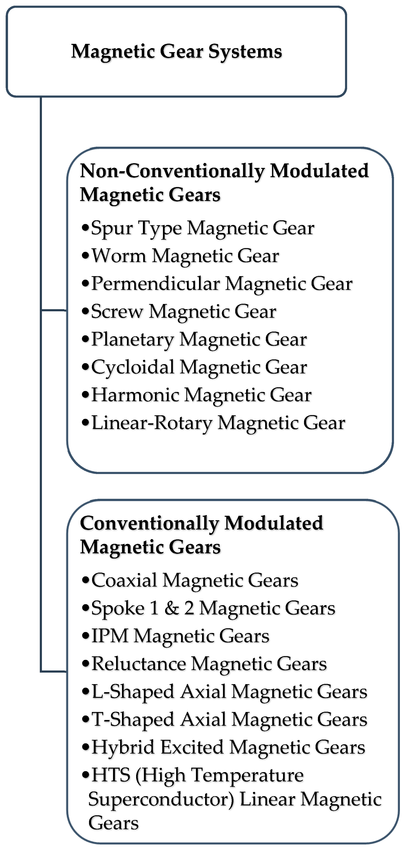
Figure 2.
Conventional Non-Modulated MG Topologies.
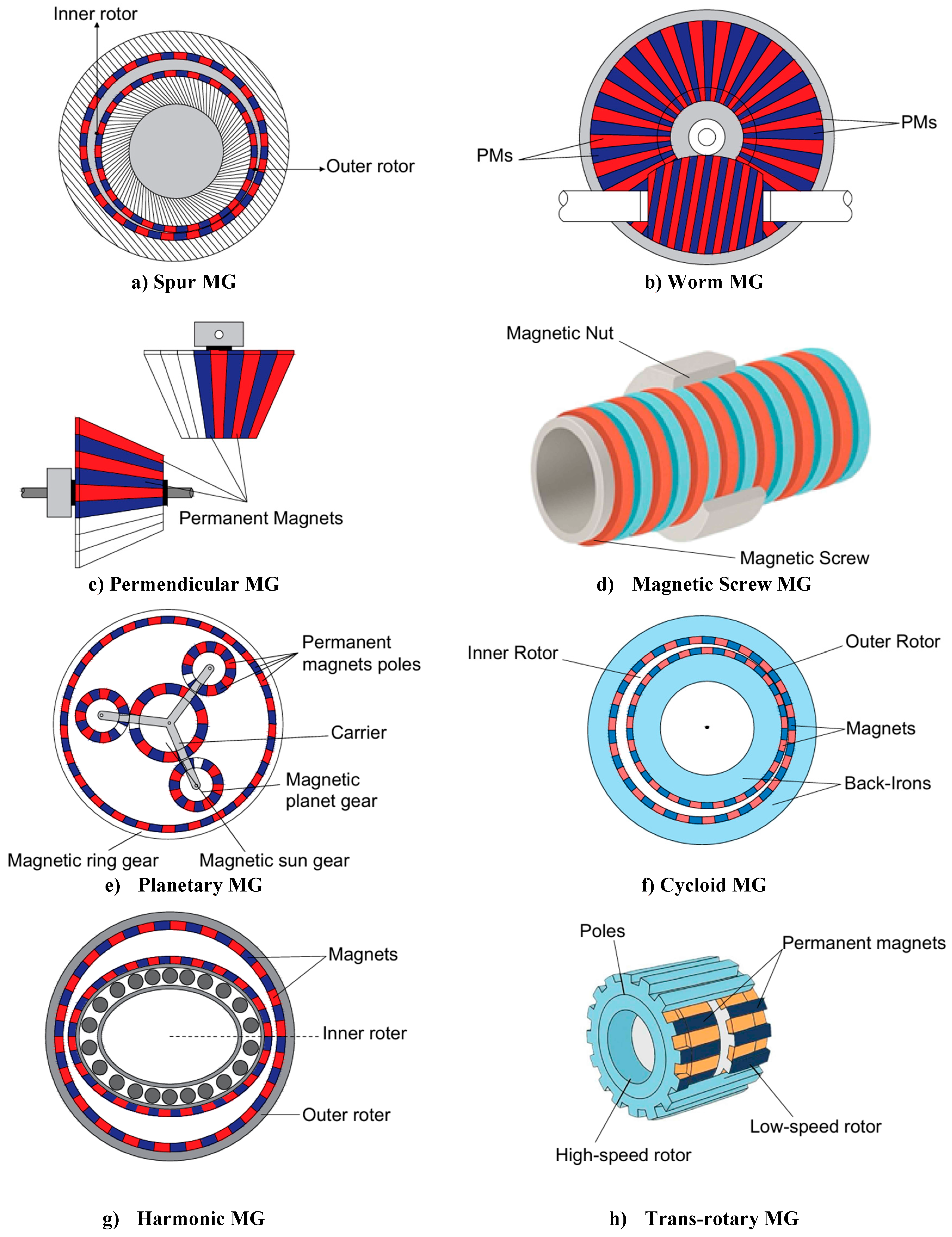
Figure 3.
Modulated MG topologies.
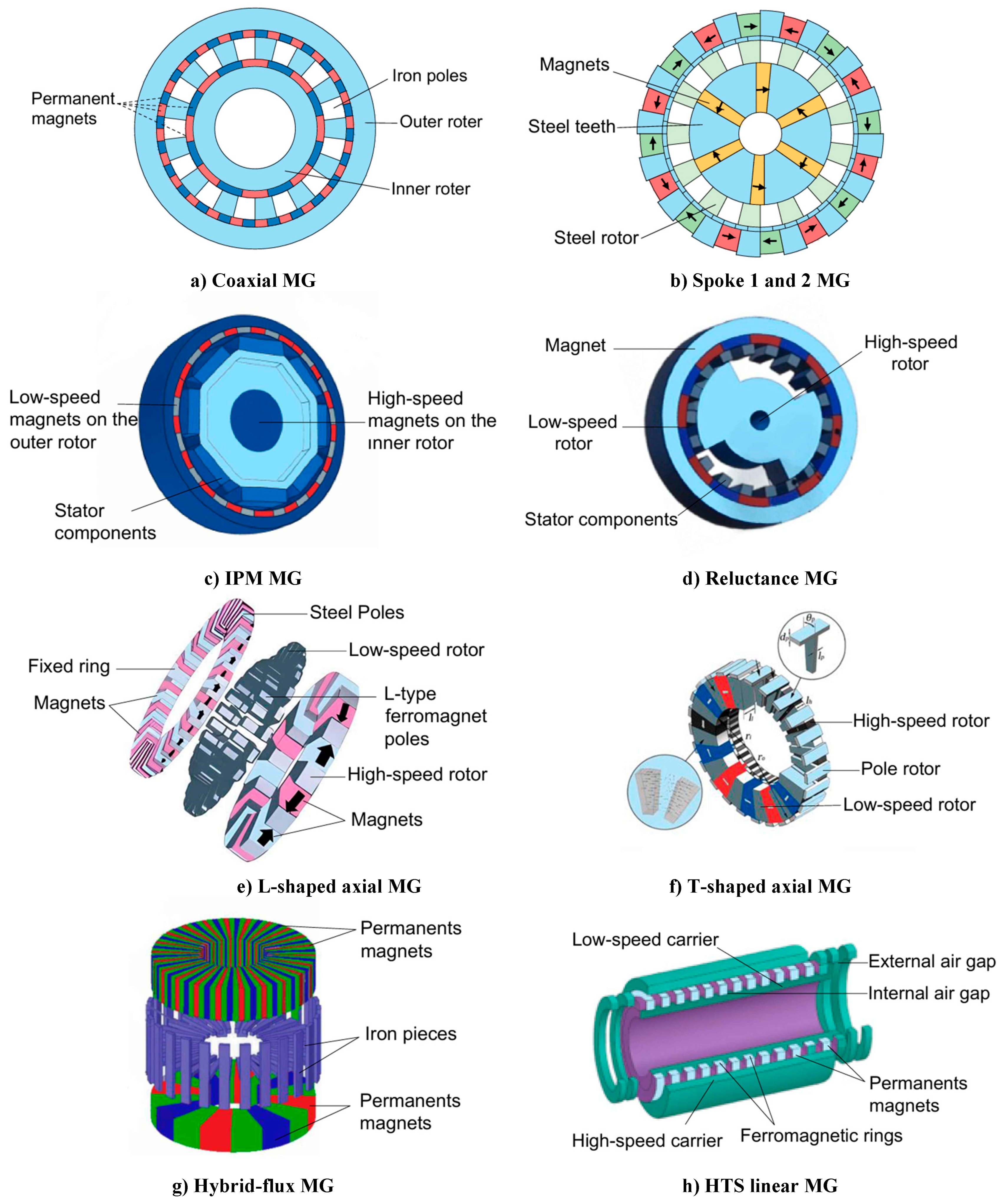
Figure 4.
Representation of the drive gear system and torque transmission.
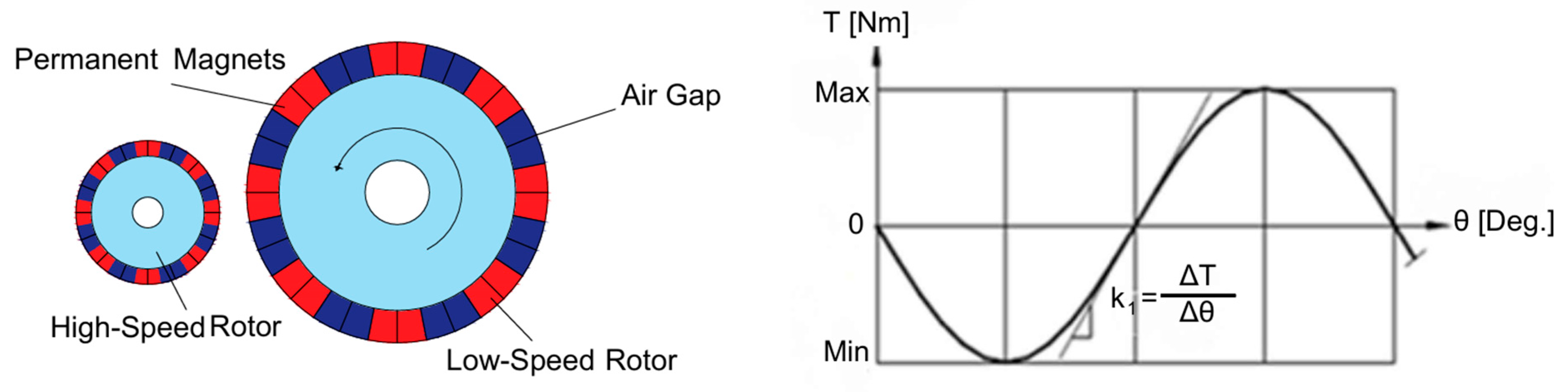
Figure 5.
Structures of a mechanical gear (left) and a permanent magnet magnetic gear (right).
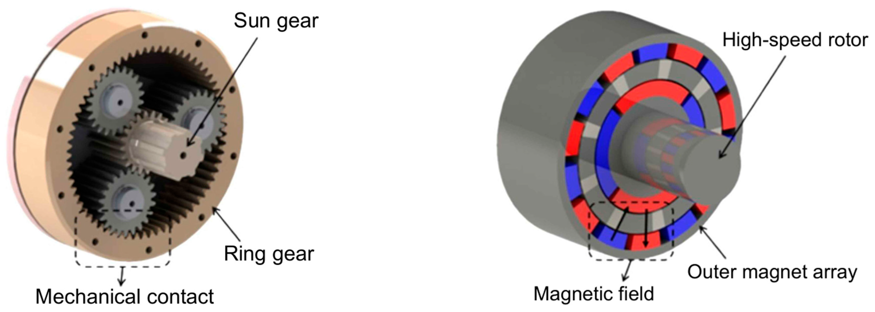
Figure 6.
Coaxial magnetic gears based on rotating components: configurations where (from left to right) the carrier is fixed, the outer rotor is fixed, and the inner rotor is fixed.
Figure 6.
Coaxial magnetic gears based on rotating components: configurations where (from left to right) the carrier is fixed, the outer rotor is fixed, and the inner rotor is fixed.
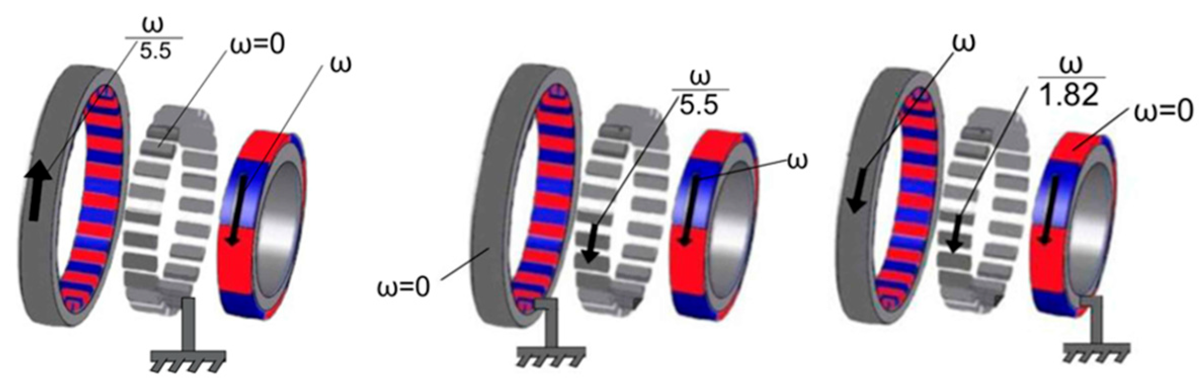
Figure 7.
Halbach array (a) magnet orientations (b) flux lines.
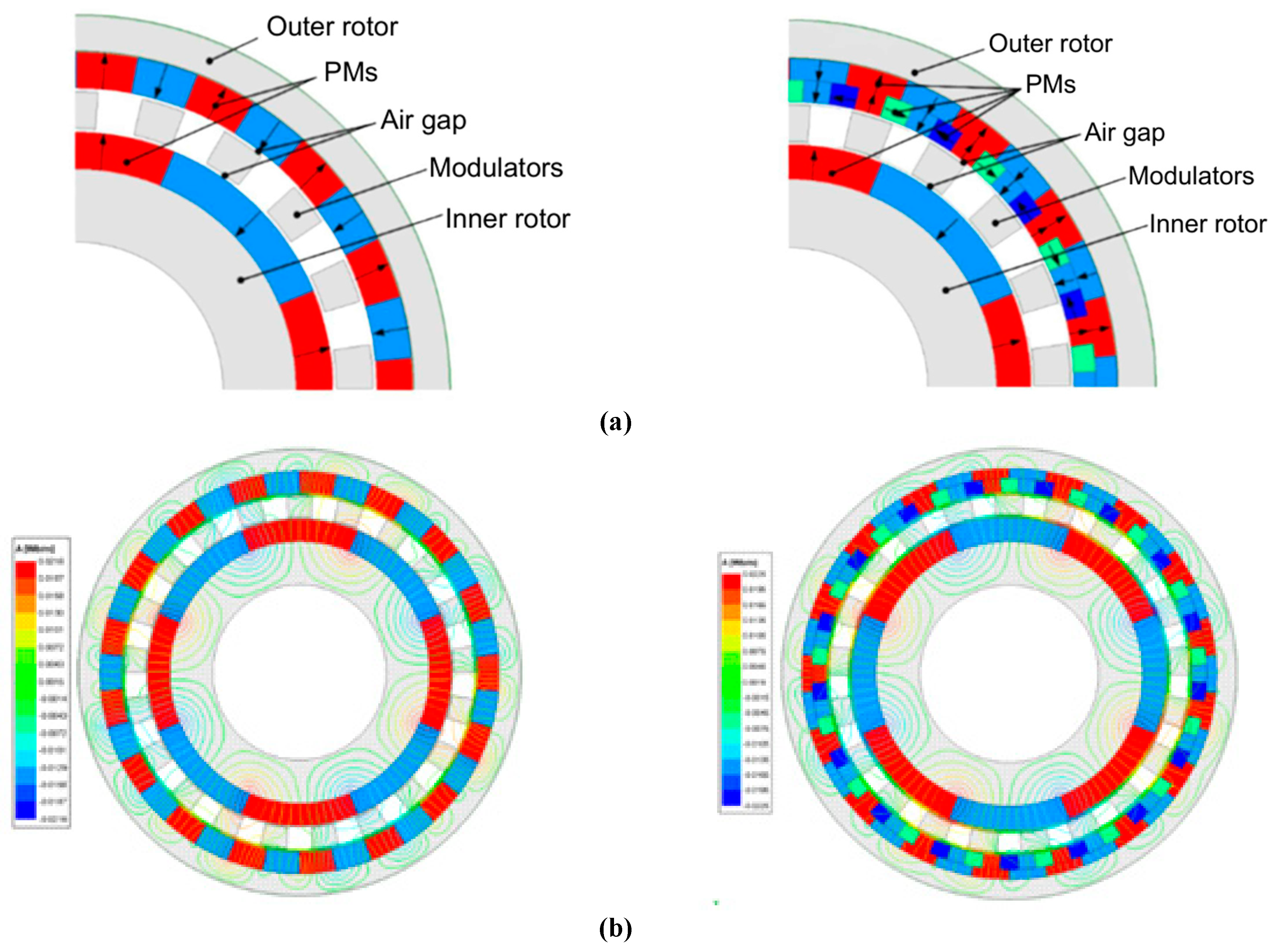
Figure 8.
Structure of a coaxial magnetic gear with a slotted magnetic modulation ring [55].
Figure 8.
Structure of a coaxial magnetic gear with a slotted magnetic modulation ring [55].
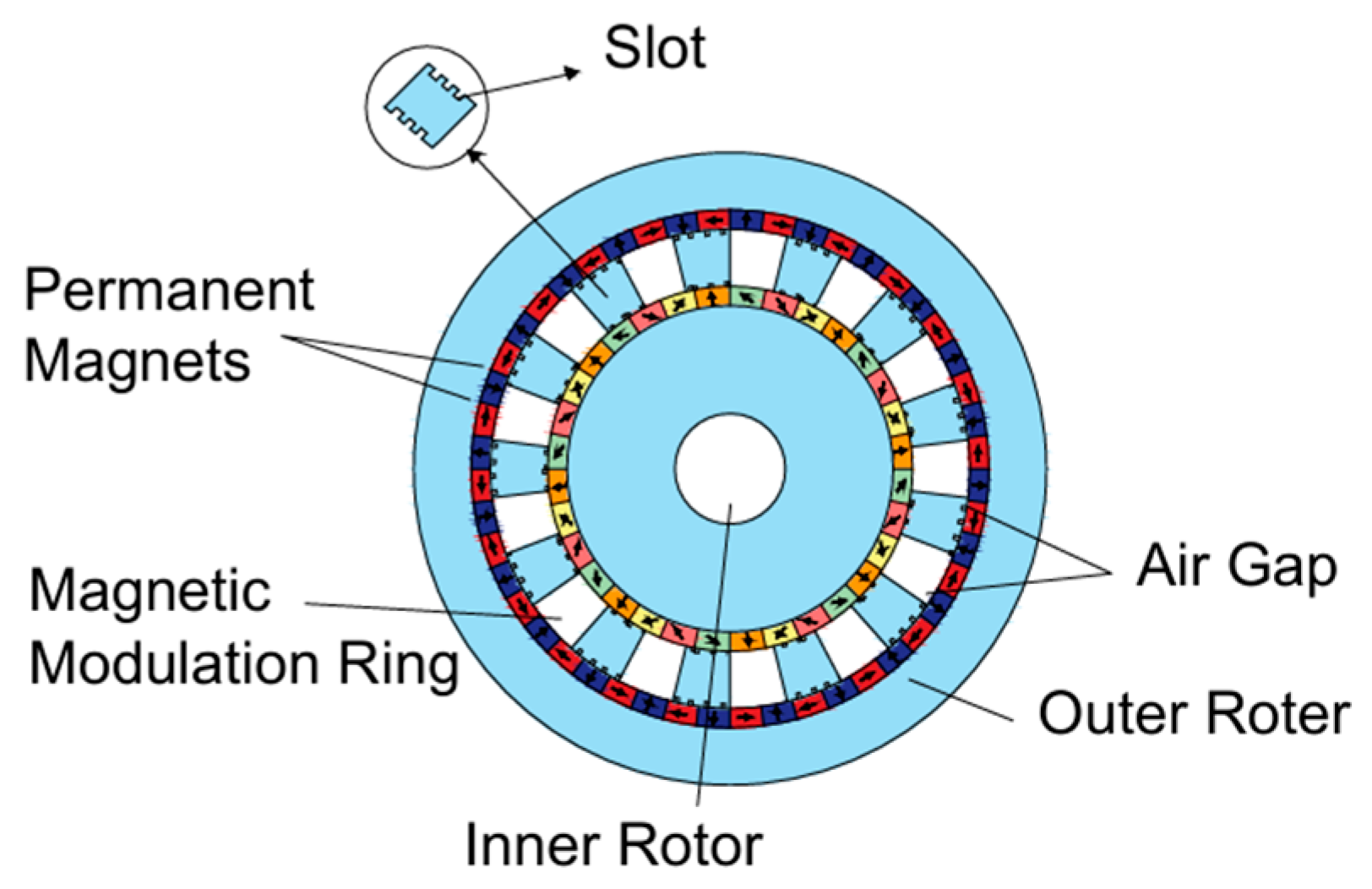
Figure 9.
Performance Comparison of Materials Using Normalized Radar Chart.
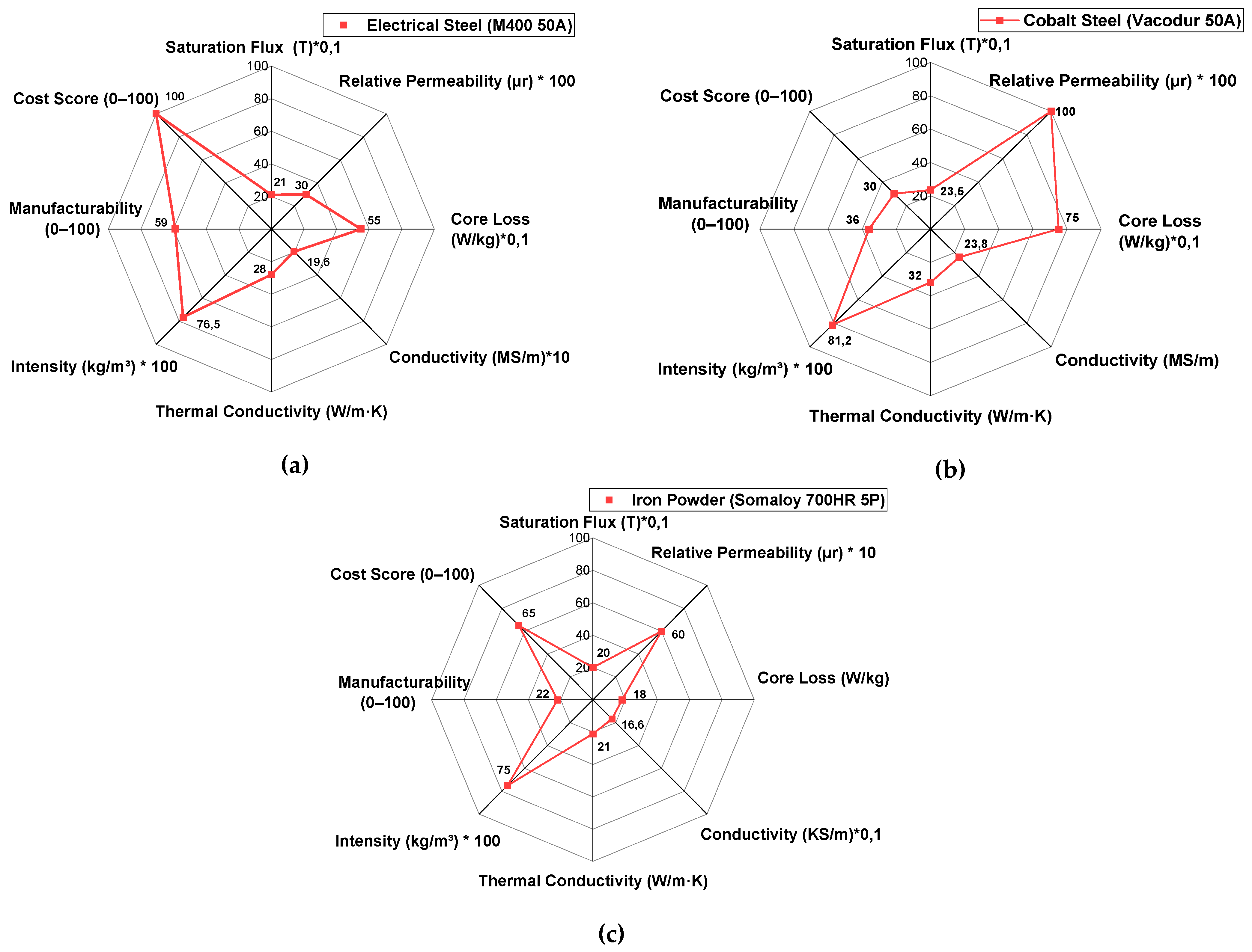
Figure 10.
B-H Characteristic curves of M400-50A, Somaloy 700HR 5P, and Vacodur 50 materials [82].
Figure 10.
B-H Characteristic curves of M400-50A, Somaloy 700HR 5P, and Vacodur 50 materials [82].
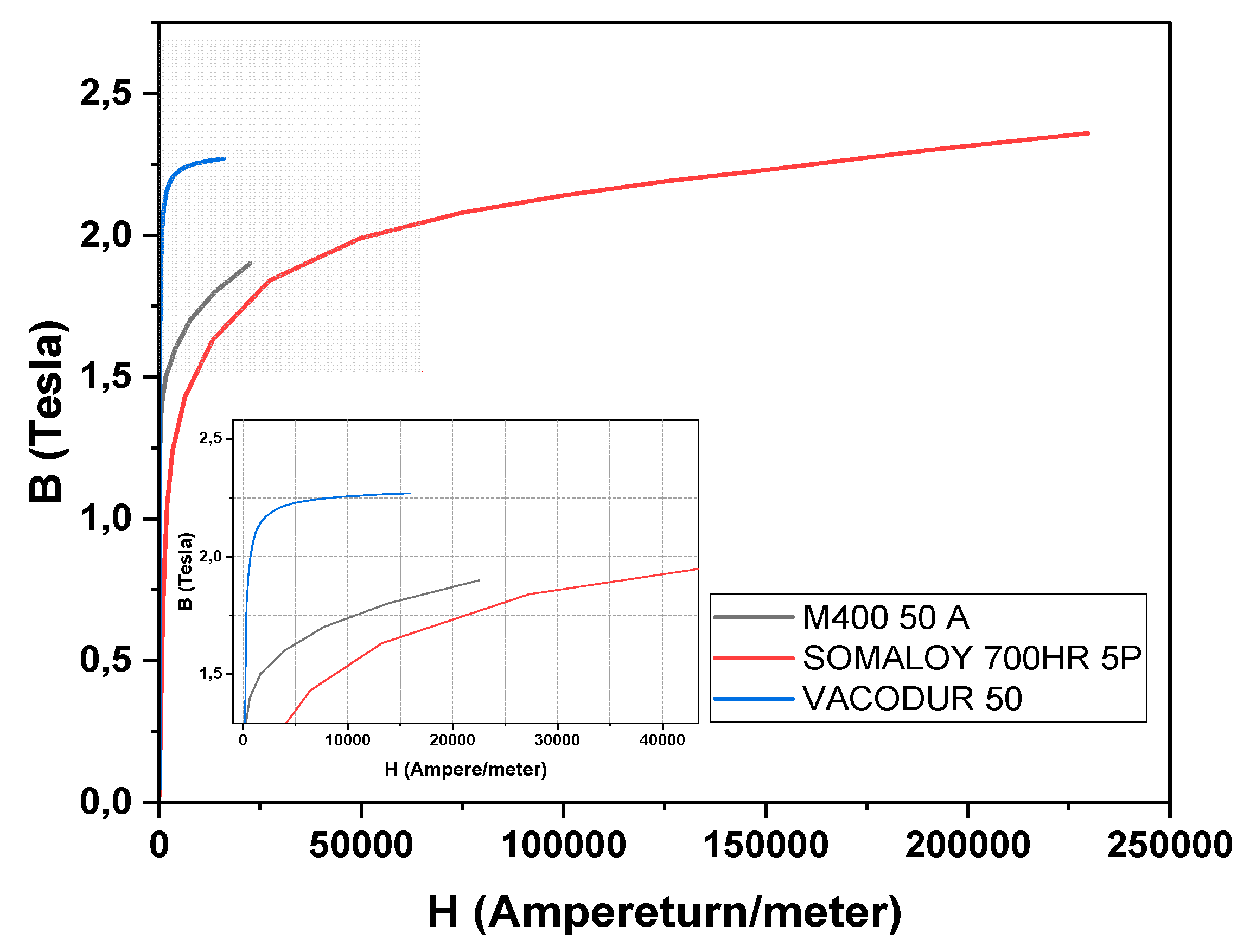
Figure 11.
Magnetic permeability curves of M400-50A, Somaloy 700HR 5P, and Vacodur 50 materials [82].
Figure 11.
Magnetic permeability curves of M400-50A, Somaloy 700HR 5P, and Vacodur 50 materials [82].
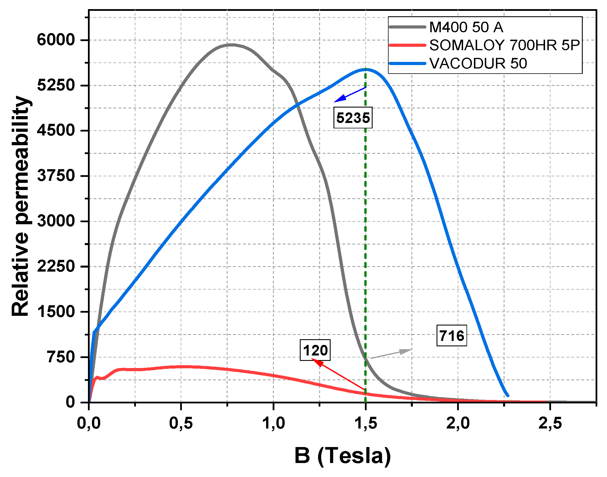
Figure 13.
Distribution of scientific publications on magnetic gear systems across different application areas, based on the categorization of references reviewed in this study.
Figure 13.
Distribution of scientific publications on magnetic gear systems across different application areas, based on the categorization of references reviewed in this study.
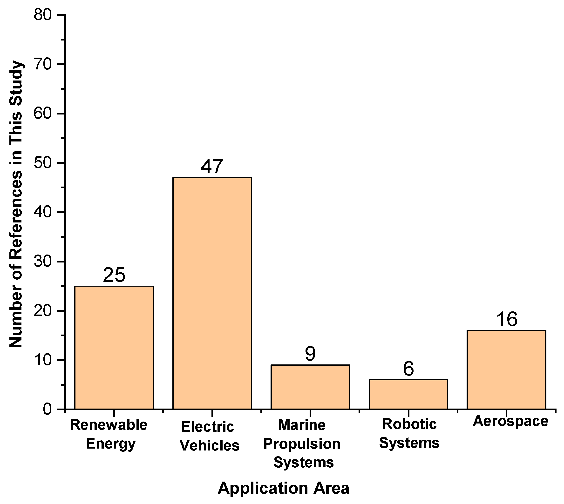
Table 1.
Advantages and Disadvantages of NdFeB, AlNiCo, and SmCo Magnets.
| Type | Advantages | Disadvantages |
|---|---|---|
| NdFeB | High energy and flux density per unit volume | Low Curie temperature and high cost |
| AlNiCo | High Curie temperature and high flux density | Low coercivity, brittleness, and costliness |
| SmCo | High coercive force, high flux density, and resistance to heat | High cost and fabrication complexity |
Table 2.
Comparison of Different Types of Permanent Magnets [54].
Table 2.
Comparison of Different Types of Permanent Magnets [54].
| Permanent Magnet | Hc (kA/m) | Br (T) | BHmax (kJ/m³) | Tc (°C) |
|---|---|---|---|---|
| Alnico | 40-140 | 0.6-1.4 | 10-88 | 700-860 |
| Ferrite | 120-300 | 0.2-0.4 | 10-40 | 450 |
| NdFeB | 750-2000 | 1.0-1.4 | 200-400 | 310-400 |
| SmCo | 600-2000 | 0.8-1.1 | 150-240 | 720 |
Table 3.
Measurable Technical Properties of the Compared Materials [66].
Table 3.
Measurable Technical Properties of the Compared Materials [66].
| Property | Electrical Steel (M400 50A) | Iron Powder (Somaloy 700HR 5P) |
Cobalt Steel (Vacodur 50A) |
|---|---|---|---|
| Saturation Flux Density (T) | 2.10 | 2.00 | 2.35 |
| Relative Permeability (µr) | 3000 | 600 | 10000 |
| Core Loss (50 Hz, W/kg) | 5.5 | 18.0 | 7.5 |
| Electrical Conductivity (S/m) | 1.96×10⁶ | 1.66×10³ | 2.38×10⁷ |
| Thermal Conductivity (W/m·K) | 28 | 21 | 32 |
| Density (kg/m³) | 7650 | 7500 | 8120 |
| Manufacturability (0–100) | 59 | 22 | 36 |
| Cost Score (0–100) | 100 | 65 | 30 |
*Scores for Manufacturability and Cost are rated on a scale from 0 to 100, where 100 represents the most favorable (easiest to manufacture or most economical) and 0 the least favorable.
Table 4.
Core material manufacturing feasibility scores (0–100).
| Material | Production Method | Prototype | Mass Production | Average |
|---|---|---|---|---|
| M400-50A | Machining | 85 | 75 | 59 |
| Wire EDM | 80 | 40 | ||
| Investment Casting | 30 | 60 | ||
| Powder Metallurgy | 40 | 65 | ||
| Somaloy 700HR 5P | Machining | 25 | 10 | 22 |
| Wire EDM | 10 | 0 | ||
| Investment Casting | 0 | 0 | ||
| Powder Metallurgy | 40 | 90 | ||
| Vacodur 50A | Machining | 50 | 30 | 36 |
| Wire EDM | 70 | 25 | ||
| Investment Casting | 20 | 55 | ||
| Powder Metallurgy | 15 | 25 |
Disclaimer/Publisher’s Note: The statements, opinions and data contained in all publications are solely those of the individual author(s) and contributor(s) and not of MDPI and/or the editor(s). MDPI and/or the editor(s) disclaim responsibility for any injury to people or property resulting from any ideas, methods, instructions or products referred to in the content. |
© 2025 by the authors. Licensee MDPI, Basel, Switzerland. This article is an open access article distributed under the terms and conditions of the Creative Commons Attribution (CC BY) license (http://creativecommons.org/licenses/by/4.0/).
Copyright: This open access article is published under a Creative Commons CC BY 4.0 license, which permit the free download, distribution, and reuse, provided that the author and preprint are cited in any reuse.


