
Submitted:
01 July 2025
Posted:
02 July 2025
You are already at the latest version
Abstract
In our previous work we developed a neuromorphic decoder of intended movements of tetraplegic patients using ECoG recordings from brain motor cortex called Motor Control Decoder (MCD). Even though the training data was labeled based on the desired movement, there is no guarantee that the patient is satisfied by the action of the effectors. Hence the need for classification of brain signals as satisfactory/unsatisfactory is obvious. Based on previous work here we upgrade our neuromorphic MCD with a Neural Response Decoder (NRD) that is intended to predict whether ECoG data is satisfactory or not in order to improve MCD accuracy. The main aim is to design an actor-critic structure able to adapt via reinforcement learning the MCD (actor) based on NRD (critic) predictions. For this aim NRD was trained using not only ECoG signal but also the MCD prediction or prescribed intended movement of the patient. The achieved accuracy of trained NRD is satisfactory and it contributes to improved MCD performance. However, further work has to be done to fully utilize the NRD for MCD performance optimization in on-line manner. Possibility to include feedback from the patient would allow for further improvement of MCD-NRD accuracy.
Keywords:
brain-machine interfaces
; neural response decoder
; spiking neural networks
; neuromorphic systems
; ECoG
; personalized neuro-prosthetics
1. Introduction
Recent advancements in Brain-Computer Interface (BCI) technology significantly improved their reliability [1,2] providing revolutionary benefits to patients with neurological conditions such as stroke, spinal cord injuries, and neuro-degenerative disorders [3,4]. In particular, the BCIs applications to human prosthetics control demonstrated remarkable progress in the last decade [5,6,7,8,9]. A pioneering work using ElectroCorticoGram (ECoG) mesurements from the motor cortex in the brain to decode movement intentions of tetraplegic patients has been reported in [10,11,12]. The performance of the developed Motor Control Decoder (MCD) allows the patients to use the neuro-prosthesis for several weeks without recalibration. However, an unsupervised recalibration/adaptation would be a great added value for home use of such a BCI controlled device.
For the aim of auto-adaptation of MCD feedback of how it performs on given task is beneficial. Different methods for assessing a person’s performance and for delivering feedback are used in different scenarios [6,8,9,13,14]. For the aim of MCD training the patient was asked to imagine desired movement and recorded ECoG signals are marked accordingly. However, since there is no guarantee that the patient is satisfied by the effector actions, the need for classification of brain signals as satisfactory/unsatisfactory raised. For this aim in [13] each movement of prosthetic device provoked by a patient’s brain signals and decoded by a well trained MCD was labeled as satisfactory or not satisfactory in dependence on resulting error of the controller (MCD). Only satisfactory brain signals were used to train the MCD. Then another model for prediction of the neural response quality, called Neural Response Decoder (NRD), was trained. A further aim of NRD was to allow for auto-adaptation of the MCD in on-line mode. However, since the initial MCD, supposed to be well trained, might not be perfect such a labeling of ECoG data as satisfactory/unsatisfactory might not be always exact.
In our previous work [15] a novel neuromorphic framework of a BMI system for prosthetics control via decoding ECoG brain signals was described. It includes a three-dimensional spike timing neural network (3D-SNN) for brain signals features extraction and an on-line trainable recurrent reservoir structure (Echo state network (ESN)) for Motor Control Decoding (MCD). The decoder auto-adapts to the incoming brain signals via Spike Timing Dependent Plasticity (STDP) of connections (synapses) in the 3D-SNN structure. In further work [16] a novel technique for features extraction from raw ECoG data was proposed that improved significantly accuracy of the MCD from [15].
Based on our previous work here we upgrade our neuromorphic MCD with a NRD that should be able to predict whether the decoder actions and/or ECoG data from the patient is correct (satisfactory) or not. The main aim is to design an actor-critic structure able to adapt via reinforcement learning MCD (actor) based on NRD (critic) predictions. It would allow for continuous adaptation of the decoder to changes in brain signals in real time.
2. Materials and Methods
2.1. Experimental Data
The developed MCD-NRD structure was trained on the data base (DB) called RUNNER. Figure 1 shows the experimental set-up.
During the data collection experiment the patient was seated in front of a computer screen where a human avatar was represented from a third person perspective. The avatar could either stand still or walk forward at a fixed speed. The RUNNER DB was collected from a patient with traumatic sensorimotor tetraplegia caused by a complete C4–C5 spinal cord injury and having implanted two chronic wireless ECoG WIMAGINE implants [17] composed of 64 planar electrodes [13,14]. The patient was involved in the “BCI and Tetraplegia” clinical trial at CEA/Clinatec (NCT02550522), which focuses on the recording and decoding of motor intentions with different effectors. Here, the patient controlled the avatar using leg motor imagery decoded by a trained MCD. Totally 9 sessions, of on average 11 min of recording, were acquired over 99 days. For blind-test of the algorithms, the database has been split in two parts: the first 7 sessions were used to train the decoder while the last 2 were left for testing the trained model accuracy.
The , i.e. the prescribed on the screen avatar state that should be predicted by MCD, has two possible values: or . The satisfaction of the decoded brain signals and achieved new state of the avatar (denoted briefly as ) was marked according to the procedure described in [13,14] as follows: after a lag of time when the instruction on the screen was changed if the avatar is in the as a result of proper decoding of patient’s ECoG signals by the MCD, it is considered as satisfactory () while if it is not - the ECoG signal was marked as non satisfactory ().
However, the way of labeling does not relay on patient’s opinion. Since the avatar states were decoded by a pre-trained MCD module, the decoding error could result either from wrong patients’ brain signals due to fatigue and distraction or from MCD incorrectness. Hence such a labeling could serve to predict an error in desired movement decoding with unknown origin.
Nevertheless, the experimental data base is a good starting point to train initial NRD that could be further refined using feedback from the patient.
2.2. Neuromorphic Framework for MCD and NRD
In our previous work [15] we described a neuromorphic structure called MCD. It was trained to predict desired by patient avatar actions from ECoG signals. Here we upgrade it with a NRD structure whose aim is to predict correctness (satisfaction) of the actions decoded by the MCD. The basic idea comes from the reinforcement learning theory [18] that is considered as a biologically plausible way our brain learns from experience via interacting with the environment and receiving a feedback about the resulting outcome. The feedback signal is called and could be very simple, e.g. a binary label or .
Figure 2 presents the proposed reinforcement learning framework. In order to transfer the terminology from the experimental set-up to the terms in control theory and reinforcement learning, we refer to the patient as an under control whose state () is assessed by the extracted features from the signals measured by the ECoG implants; the MCD will be refereed further as the (controller) that has to be optimized to generate resulting in satisfaction () rather than to non satisfaction (); the satisfaction itself is considered as binary to be predicted by the element (in our scheme the NRD). Table 1 summarizes the correspondence between experimental and RL terms.
Thus the MCD role is to generate an based on the perceived object’s state () while the NRD should predict the outcome () from the and perceived object’s state. In situation, when the movement desired by the patient is not known, a perfectly trained NRD should be able support MCD in generation of proper motion of end effectors of the exoskeleton supporting the patient. However, since the labels in RUNNER DB described above were obtained without feedback from the patient, we can’t be sure whether a wrong avatar movement is due to fatigue or distraction of the patient or because the MCD was not perfectly trained. If in the experimental set-up a feedback from the patient () is included, the RL framework will allow for simultaneous training of MCD and NRD.
The overall neuromorphic structure upgrades the MCD described in details in [15] as shown on Figure 3. It consists of the following basic modules:
- Filtering module that transforms the raw ECoG signals to input signal for 3D-SNN using Morlet wavelet transformation for multiple fundamental frequencies and their combination into a features matrix of same size as the original one [16]
- 3D recurrent SNN architecture called 3D SNN cube, spatially structured and adaptable to an individual 3D brain template, for feature extraction from processed ECoG signals. It adapts continuously to the incoming input in unsupervised mode via STDP rule.
- Two recurrent Echo State Network (ESN) structures for decoding of the desired movement (MCD) and satisfaction (NRD) from extracted features (spiking frequencies of the selected neurons in the 3D-SNN module). It can be trained on-line in supervised mode via recursive least squares (RLS) or in unsupervised regime via reinforcement learning (RL) rules.
The novel approach for ECoG signals’ features extraction is described in details in [16]. It consists of combination of 15 wavelet transformations of every portion of 59 records from the 64 ECoG electrodes’ signals for approximately 100 ms using Morlet wavelets with 15 different fundamental frequencies (from 10 to 150 Hz with step of 10 Hz). The obtained filtered ECoG signals on Figure 3 are a matrix of the same size as the original one, i.e. . It is fed to the 3D SNN cube as generating currents for the time period of approximately 100 ms to each one of the 64 neurons in the structure. The firing rates during the stimulation period of the 3D SNN cube are the ECoG features from 3D SNN fed to both MCD and NRD modules.
The top part of Figure 4 shows the 3D SNN cube structure. It consists of 64 spiking neurons (simulated by the Leaky Integrate and Fire (LIF) model) positioned at the ECoG electrode positions in the 3D space. The synaptic connections between each pair of neurons were randomly generated with weights proportional to their distance in the 3D space. The positive connections are marked in red while the negative once - in blue. All synapses are plastic, i.e. their strength (weight) adapts continuously to the input signals via the associative learning rule called Spike Timing Dependent Plasticity (STDP). The auto-adaptation in the 3D SNN structure reflects the spatio-temporal dependence of ECoG signals thus accounting for both mutual positions of the ECoG electrodes and changes of the recorded signals with time. Bottom part on Figure 4 shows the initial and two snapshots (after training and after testing) of the connections weights in the 3D-SNN structure. The color of each dot corresponds to the magnitude of the connection weight between each pair of neurons, numbered from 1 to 64 on both x and y axes. We observe that the initial weights (most left plot) converge very fast to connectivity corresponding to the model input signals and continue with small adaptation changes during training (middle plot) and testing (right plot) phases.
Both actor and critic modules are fast trainable recurrent neural network structures called Echo state networks (ESN) [19]. They consist of a randomly connected pool of neurons with hyperbolic tangent nonlinear activation function and a linear readout with weights trainable via least squares method.
The MCD is trained to predict the desired movement () of the prosthetic device (in current experiment the avatar on the screen) while the NRD - to predict whether the brain signal from the ECoG generated desired () or incorrect () movements. The output of NRD is considered as prediction of reward/punish signal in form of satisfaction/no satisfaction. This signal should allow for adjustment of the actor behavior (MCD predictions) so as to decrease its error.
2.3. Software Implementation
All modules are written in Python, version 3.8.9. The 3D-SNN is based on NEST simulator library, version 3.3 [20] while the rest of code exploits numpy, SciPy and other Python libraries for mathematical calculations. The software works in pseudo-online mode reading from files the next portion of 59 records from ECoG electrodes, desired decoder outputs ( and ) from file and generating as output as well as for current time period. During training the model parameters are adjusted in supervised mode while during testing the model output is kept in csv files.
The adjustable in supervised mode parameters of the model are the output connection weights of the ESN modules. They are tuned incrementally with every new input/output training data pair via recursive least squares (RLS) method. The 3D-SNN connection weights auto-adapt via the STDP rule continuously. The 3D SNN cube state is the membrane potentials of all the neurons in the structure. All model parameters are kept in csv files.
3. Methodology
We investigated four training approaches and performed three testing experiments described further.
3.1. Training Approaches
The training algorithm is shown as Algorithm 1. , , and denote the four training approaches.
| Algorithm 1 Pseudo-code of training algorithm |
|
Initialization Initialize and modules parameters Compose 3D-SNN module using ECoG positions Initialize the cube connection weights based on neurons’ distances while do
|
Since in case of non satisfaction it is supposed that MCD should generate the opposite state, first we’ve performed the following two training approaches:
- denoted further as TA1 (Figure 5): Use desired state of MCD from the DB denoted as as target for MCD and input to NRD no matter whether the training example is labeled as satisfaction or non satisfaction.
- denoted further as TA2 (Figure 6): Use swapped desired state of MCD denoted as (if revert to and vise versa) as target fro MCD and input for NRD if the training example is labeled as non satisfaction in the DB ().
Since in real time the decoder will not be aware of exact target movement of the test subject, it is important to be able to rely on predictions from MCD to train and test NRD. In order to start training of NRD with better trained MCD we performed also the next two training approaches:
- : Use the (TA1) to train initial model of both MCD and NRD using only first training session from the DB.
The (TA3) and (TA4) training approaches exploit the idea from the previous once: to use the or to invert it (reverted ) based on the value of the for training of the MCD.
All training approaches relay on model target output data from DB so they could be implemented in off-line mode. In real time, if the target output was available, the RLS algorithm will allow to adjust the model parameters in on-line mode too.
3.2. Testing Experiments
The testing algorithm is shown as Algorithm 2. and denote the first and second testing experiment, described in next section.
| Algorithm 2 Pseudo-code of testing algorithm |
|
Initialization Set and modules parameters to the trained once Compose 3D-SNN module using ECoG positions Set 3D SNN state to the achieved after training Set cube connection weights to the achieved after training values while do
|
The three testing experiments are summarized as follows:
- denoted further as TE1 (Figure 9): feed the trained NRD with desired action from DB () rather than from the trained MCD prediction. In this way we skip MCD imitating knowledge about instructions on the screen. However, in on-line mode the NRD must know the target action that is not always possible.
- denoted further as TE2 (Figure 10): feed the trained MCD prediction () to NRD that are not always correct but will be available in real situation. In this way the decoder works in fully on-line mode.
- denoted further as TE3: Testing of both models trained via the Third (TA3) and Fourth (TA4) training approaches was done as in the Second experiment TE2, i.e. in on-line mode.
4. Results
For the training and testing of both MCD and NRD modules we use the fully labeled data from training sessions of RUNNER DB, i.e. sessions from 1 to 7 for training and the rest of sessions (8 and 9) - for testing.
Table 2 and Table 3 show the NRD testing accuracy from the and the for both models trained using and training approach respectively. For the we observe that when the NRD was trained using information about desired avatar movement from the instructions on the screen, it could be better trained to predict label. In case the desired actions were replaced by MCD predictions as in the however, the NRD accuracy drops significantly that is expected since the MCD is not perfectly trained.
results show that even if the model was trained using exact information about target movement as in the , testing with trained MCD predictions yields decreased accuracy in comparison with . Again results in lower model accuracy.
Testing of both models trained via the (TA3) and (TA4) training approaches was done as in the TE2 (Figure 10). Table 4 shows testing accuracy of the NRD from the third experiment. It is above the accuracy achieved from the and below the accuracy from the . The yielded model with better accuracy that is expected result.
Finally, we tested whether predictions from the trained NRD could be applied to improve the MCD accuracy as it is shown by the dashed arrow from NRD to MCD on Figure 10. The results from the and experiment are the same since the MCD was trained in the same way in both cases. They are shown in Table 5. Table 6 shows the MCD accuracy from the .
We did not observe significant difference of MCD accuracy in / and . However, in all experiments using training approaches TA2 () and TA4 () with reverting of in case of yielded better accuracy of MCD in comparison with the (TA1) and (TA3) training approaches (without reverting of ). This proves the hypothesis that even if NRD is not perfectly trained, its predictions can be applied to improve MCD accuracy during real time work of the decoder.
5. Discussion
The results about NRD accuracy reported here demonstrate that if the NRD is given the target action to be performed by MCD it is able to distinguish correct from incorrect decoding of brain signals with much higher accuracy in comparison with the case when it is given only the brain signals. However, if we start training both NRD and MCD using knowledge about target actions and then let the NRD use pretrained MCD predictions, the achieved NRD accuracy is significantly higher.
The testing results demonstrated also that even non-perfectly trained NRD could improve the MCD predictions in a pseudo on-line mode if the MCD was trained with reverting of in case of .
In order to be able to exploit the NRD predictions for auto-adaptation of MCD, the proposed RL framework needs to be applied in real time with the patient in the loop as in Figure 2. This will allow communication with the patient and observation of changes in his/her brain signals, provoked by adjustment of both MCD and NRD. Further work in this direction using true reinforcement learning algorithm will allow to fully utilize the NRD for MCD performance optimization in on-line manner.
6. Conclusions
The proposed neuromorphic NRD system inspired by reinforcement learning theory proves to be a good idea to be explored further. Even though we did not have the opportunity to perform real time experiments with patient, the collected experimental data base allowed to test several training and testing approaches. We demonstrated that if training of NRD starts with information about correct target behavior of MCD, this will be a good starting point for further reinforcement training of both MCD and NRD parts of the decoder.
Further experiments in real time with patient in loop would allow for even better results. We believe that the patient must be asked about his satisfaction in order to achieve better auto-adaptation of his brain signals decoder during its exploitation in real life situations. Reinforcement learning would allow to continuously re-adjust the decoder in real time.
Author Contributions
Conceptualization and methodology: N.K. and P.K.-H.; software and simulation experiments: G.R., S.Y., A.B. and S.N.; experimental data collection: H.L.deM.; data curation: F.S.-S. and T.A.; writing—original draft preparation: N.K., P.K.-H. and H.L.deM.; visualization: S.N.. All authors have read and agreed to the published version of the manuscript.
Funding
This research is funded by the European Commission under the HORIZON-EIC action “Auto-adaptive Neuromorphic Brain Machine Interface: toward fully embedded neuroprosthetics (NEMO-BMI)”, No 101070891/01.10.2022NEMO-BMI (https://nemo-bmi.net, accessed on 9 March 2025).
Informed Consent Statement
Not applicable. The experimental data for models’ training and testing was provided by NEMO-BMI project coordinator CEA.
Data Availability Statement
No new data were created or analyzed in this study. This study presents only the MCD model structure and accuracy assessment by simulations.
Acknowledgments
CEA Clinatec and CHUGA provided anonymized and processed data from the ongoing clinical trial BCI & tetraplegia registered on ClinicalTrials.gov as NCT02550522. CEA Clinatec team also computed the prediction performances. IICT-BAS team designed MCD structure and software and performed training and testing experiments on DBs provided by CEA. All calculations were performed on the supercomputer HEMUS at the Centre of Excellence in Informatics and ICT, financed by the OP SESG and co-financed by the EU through the ESIF.
Conflicts of Interest
The authors declare no conflicts of interest.
References
- Rudroff, T. Decoding thoughts, encoding ethics: A narrative review of the BCI-AI revolution. Brain Res. 2025, 1850, 149423. [Google Scholar] [CrossRef] [PubMed]
- Sumithra, M.G.; Dhanaraj, R.K.; Milanova, M.; Balusamy, B.; Venkatesan, C. (Eds.) Brain-Computer Interface: Using Deep Learning Applications; Wiley: Hoboken, NJ, US, 2023. [Google Scholar]
- Awuah, W.A.; Ahluwalia, A.; Darko, K.; Sanker, V.; Tan, J.K.; Pearl, T.O.; Ben-Jaafar, A.; Ranganathan, S.; Aderinto, N.; Mehta, A.; et al. Bridging Minds and Machines: The Recent Advances of Brain-Computer Interfaces in Neurological and Neurosurgical Applications. World Neurosurg. 2024, 189, 138–153. [Google Scholar] [CrossRef] [PubMed]
- Paul, D.; Mukherjee, M.; Bakshi, A. A Review of Brain-Computer Interface. In Advances in Medical Physics and Healthcare Engineering; Mukherjee, M., Mandal, J., Bhattacharyya, S., Huck, C., Biswas, S., Eds.; Lecture Notes in Bioengineering; Springer: Singapore, 2021; pp. 507–531. [Google Scholar]
- Ajiboye, A.B.; Willett, F.R.; Young, D.R.; Memberg, W.D.; Murphy, B.A.; Miller, J.P.; Walter, B.L.; Sweet, J.A.; Hoyen, H.A.; Keith, M.W.; et al. Restoration of reaching and grasping movements through brain-controlled muscle stimulation in a person with tetraplegia: A proof-of-concept demonstration. Lancet 2017, 389, 1821–1830. [Google Scholar] [CrossRef] [PubMed]
- Buttfield, A.; Ferrez, P.W.; Millan, J.R. Towards a robust BCI: Error potentials and online learning. IEEE Trans. Neural Syst. Rehabil. Eng. 2006, 14, 164–168. [Google Scholar] [CrossRef] [PubMed]
- Eliseyev, A.; Auboiroux, V.; Costecalde, T.; Langar, L.; Charvet, G.; Mestais, C.; Aksenova, T.; Benabid, A.L. Recursive Exponentially Weighted N-way Partial Least Squares Regression with Recursive-Validation of Hyper-Parameters in Brain-Computer Interface Applications. Sci. Rep. 2017, 7, 16281. [Google Scholar] [CrossRef] [PubMed]
- Orsborn, A.L.; Moorman, H.G.; Overduin, S.A.; Shanechi, M.M.; Dimitrov, D.F.; Carmena, J.M. Closed-Loop Decoder Adaptation Shapes Neural Plasticity for Skillful Neuroprosthetic Control. Neuron 2014, 82, 1380–1393. [Google Scholar] [CrossRef] [PubMed]
- Wodlinger, B.; Downey, J.E.; Tyler-Kabara, E.C.; Schwartz, A.B.; Boninger, M.L.; Collinger, J.L. Ten-dimensional anthropomorphic arm control in a human brain-machine interface: Difficulties, solutions, and limitations. J. Neural Eng. 2014, 12, 016011. [Google Scholar] [CrossRef] [PubMed]
- Benabid, A.L.; Costecalde, T.; Eliseyev, A.; Charvet, G.; Verney, A.; Karakas, S.; Foerster, M.; Lambert, A.; Morinière, B.; Abroug, N.; et al. An exoskeleton controlled by an epidural wireless brain–machine interface in a tetraplegic patient: A proof-of-concept demonstration. Lancet Neurol. 2019, 18, 1112–1122. [Google Scholar] [CrossRef] [PubMed]
- Lorach, H.; Galvez, A.; Spagnolo, V.; Martel, F.; Karakas, S.; Intering, N.; Vat, M.; Faivre, O.; Harte, C.; Komi, S.; et al. Walking naturally after spinal cord injury using a brain–spine interface. Nature 2023, 618, 126–133. [Google Scholar] [CrossRef] [PubMed]
- Moly, A.; Costecalde, T.; Martel, F.; Martin, M.; Larzabal, C.; Karakas, S.; Verney, A.; Charvet, G.; Chabardes, S.; Benabid, A.L.; et al. An adaptive closed-loop ECoG decoder for long-term and stable bimanual control of an exoskeleton by a tetraplegic. J. Neural Eng. 2022, 19, 026021. [Google Scholar] [CrossRef] [PubMed]
- Rouanne, V. Adaptation of Discrete and Continuous Intracranial Brain-Computer Interfaces Using Neural Correlates of Task Performance Decoded Continuously From the Sensorimotor Cortex of a Tetraplegic. Ph.D. Thesis, Université Grenoble Alpes, Saint-Martin-d’Hères, France, 2022. [Google Scholar]
- Rouanne, V.; Costecalde, T.; Benabid, A.L.; Aksenova, T. Unsupervised adaptation of an ECoG based brain-computer interface using neural correlates of task performance. Sci. Rep. 2022, 12, 21316. [Google Scholar] [CrossRef] [PubMed]
- Rusev, G., Yordanov, S., Nedelcheva, S., Banderov, A., Sauter-Starace, F., Koprinkova-Hristova, P., Kasabov, N., Decoding brain signals in a neuromorphic framework for a personalized adaptive control of human prosthetics, 2025. Biomimetics 2025, 10(3), 183.
- Rusev, G., Innovative Brain Signal Feature Extraction for Personalized and Adaptive Human Prosthetics, submitted paper (under review) https://zenodo.org/records/15436393.
- Mestais, C.S.; Charvet, G.; Sauter-Starace, F.; Foerster, M.; Ratel, D.; Benabid, A.L. WIMAGINE: Wireless 64-channel ECoG recording implant for long term clinical applications. IEEE Trans. Neural Syst. Rehabil. Eng. 2015, 23, 10–21. [Google Scholar] [CrossRef] [PubMed]
- Andrew, B.; Richard, S.S. Reinforcement Learning: An Introduction, 2nd ed.; The MIT Press: Cambridge, MA, USA; London, UK, 2018. [Google Scholar]
- Jaeger, H. Tutorial on Training Recurrent Neural Networks, Covering BPPT, RTRL, EKF and the “Echo State Network” Approach; GMD Report 159, German National Research Center for Information Technology; GMD-Forschungszentrum Informationstechnik: Bonn, Germany, 2002. [Google Scholar]
- Spreizer, S.; Mitchell, J.; Gutzen, R.; Lober, M.; Linssen, C.; Trensch, G.; Jordan, J.; Plesser, H.E.; Kurth, A.; Vennemo, S.B.; et al. NEST 3.3 (3.3). Zenodo. 2022. [CrossRef]
Figure 1.
Experimental set-up for the Runner DB acquisition.
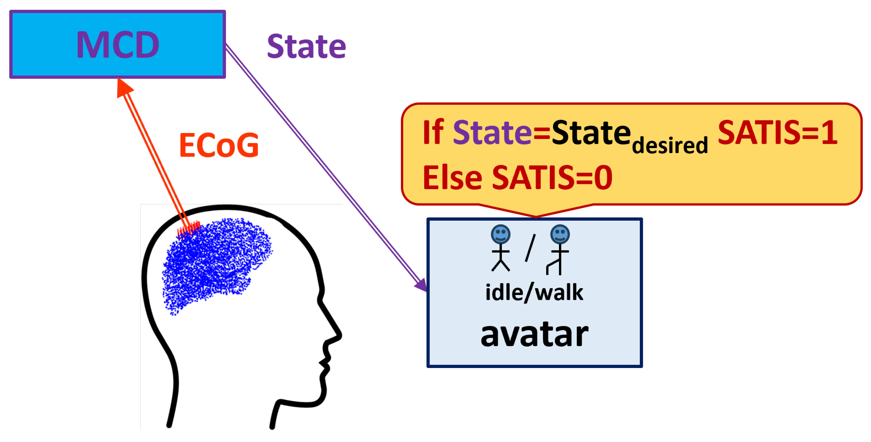
Figure 2.
Actor-critic framework of the proposed reinforcement learning scheme.
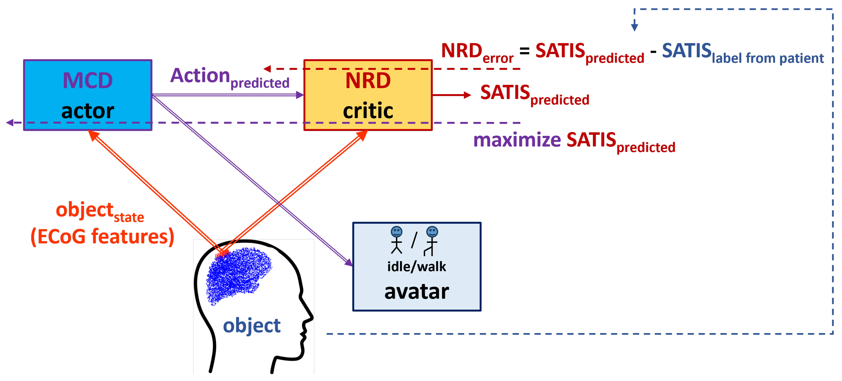
Figure 3.
Decoder structure including both MCD as actor and NRD as critic network structures.
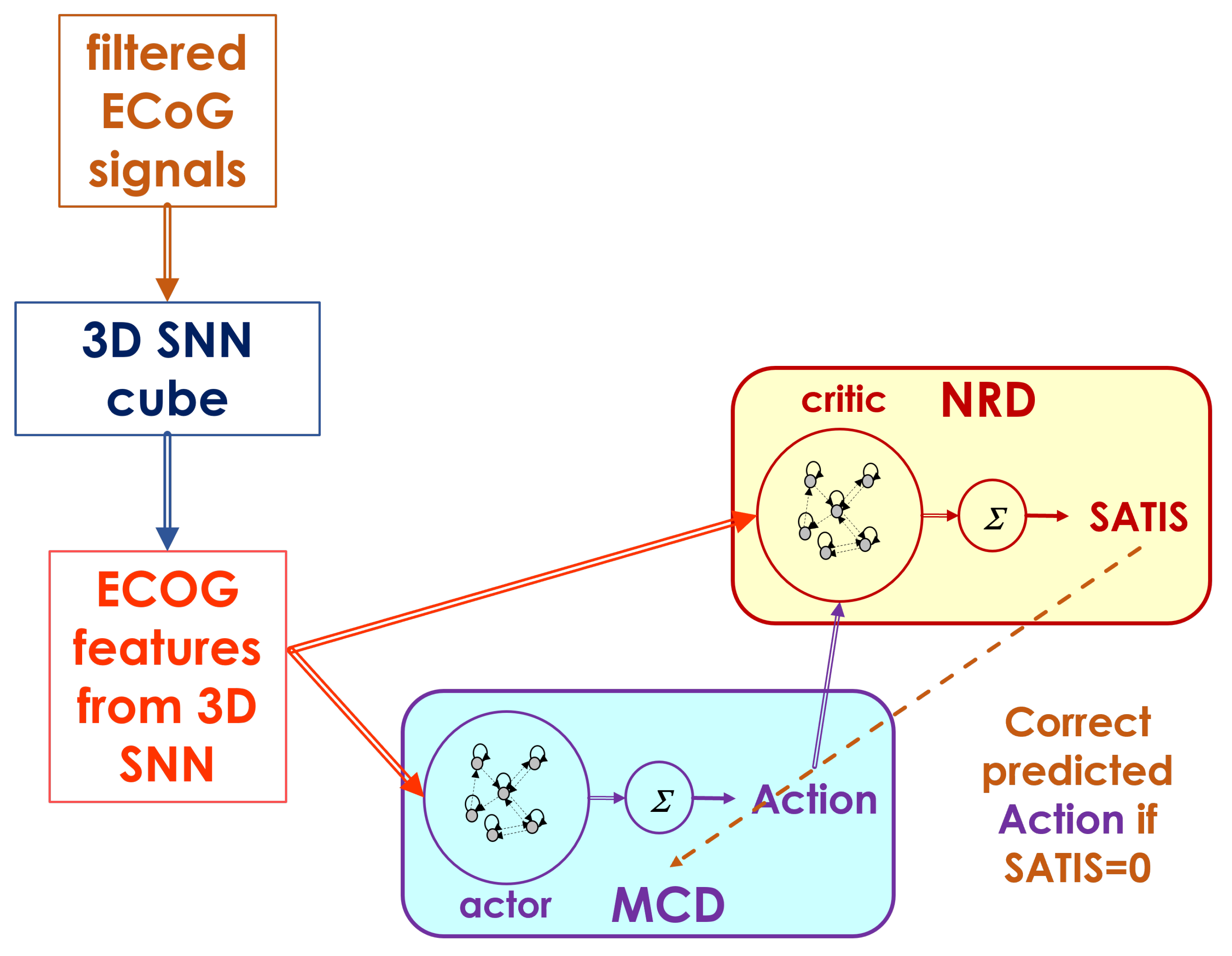
Figure 4.
Connections in 3D SNN.
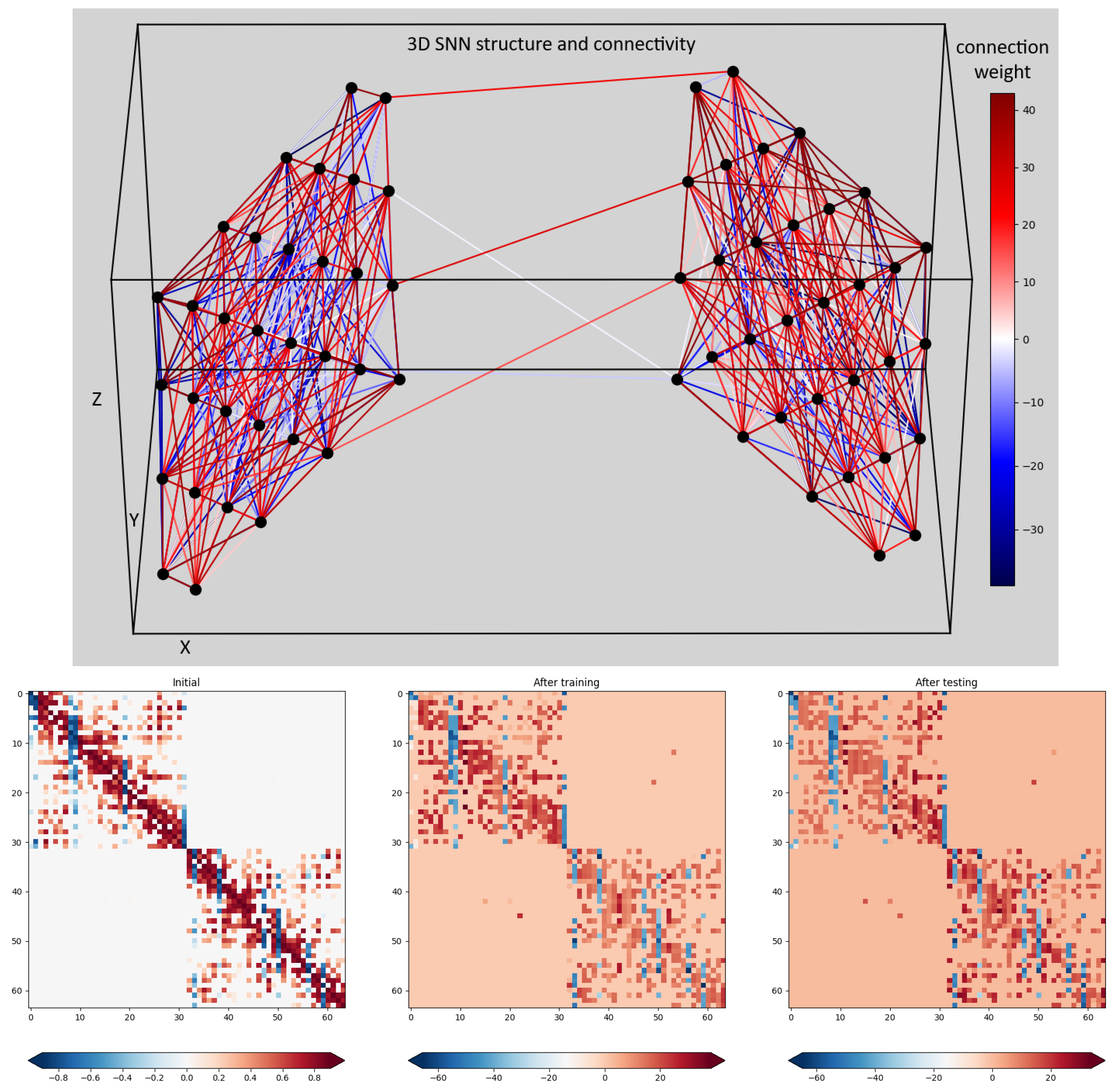
Figure 5.
Block diagram of the TA1. Solid arrows represent the input and output data to/from both NRD and MCD structures. Dashed arrows represent propagation of the training error for both action and critic networks.
Figure 5.
Block diagram of the TA1. Solid arrows represent the input and output data to/from both NRD and MCD structures. Dashed arrows represent propagation of the training error for both action and critic networks.
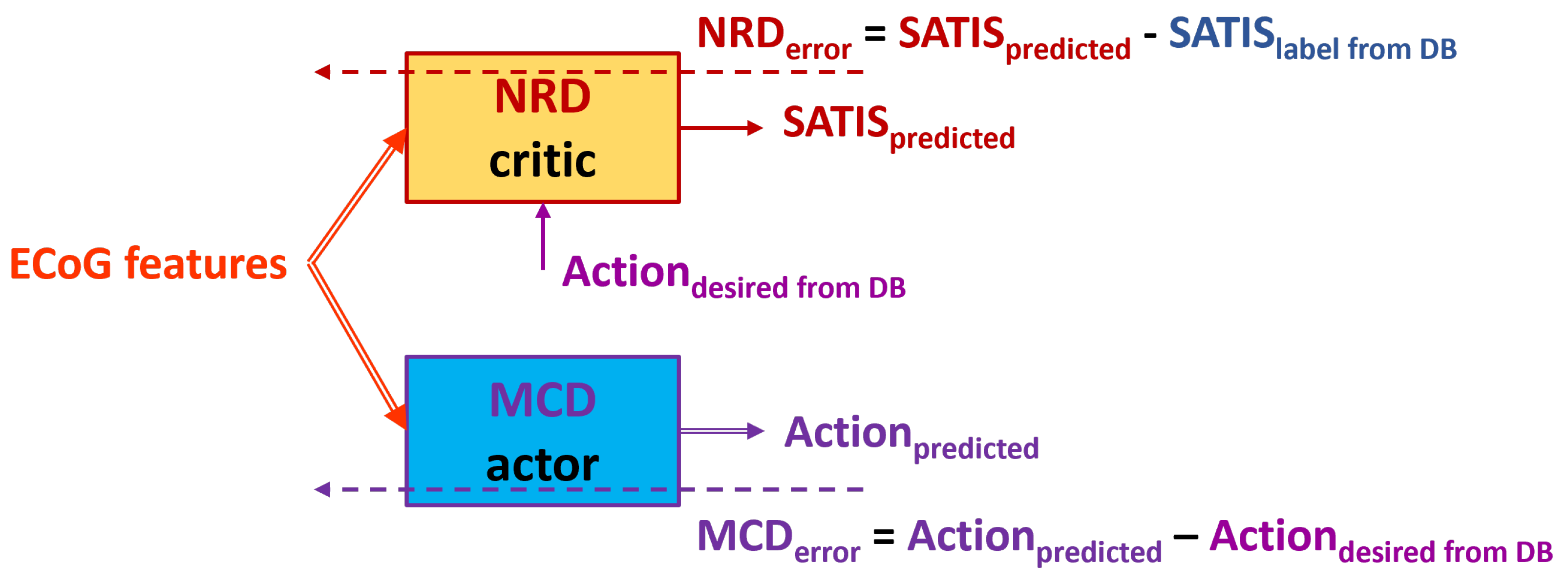
Figure 6.
Block diagram of the TA2. Solid arrows represent the input and output data to/from both NRD and MCD structures. Dashed arrows represent propagation of the training error for both action and critic networks.
Figure 6.
Block diagram of the TA2. Solid arrows represent the input and output data to/from both NRD and MCD structures. Dashed arrows represent propagation of the training error for both action and critic networks.
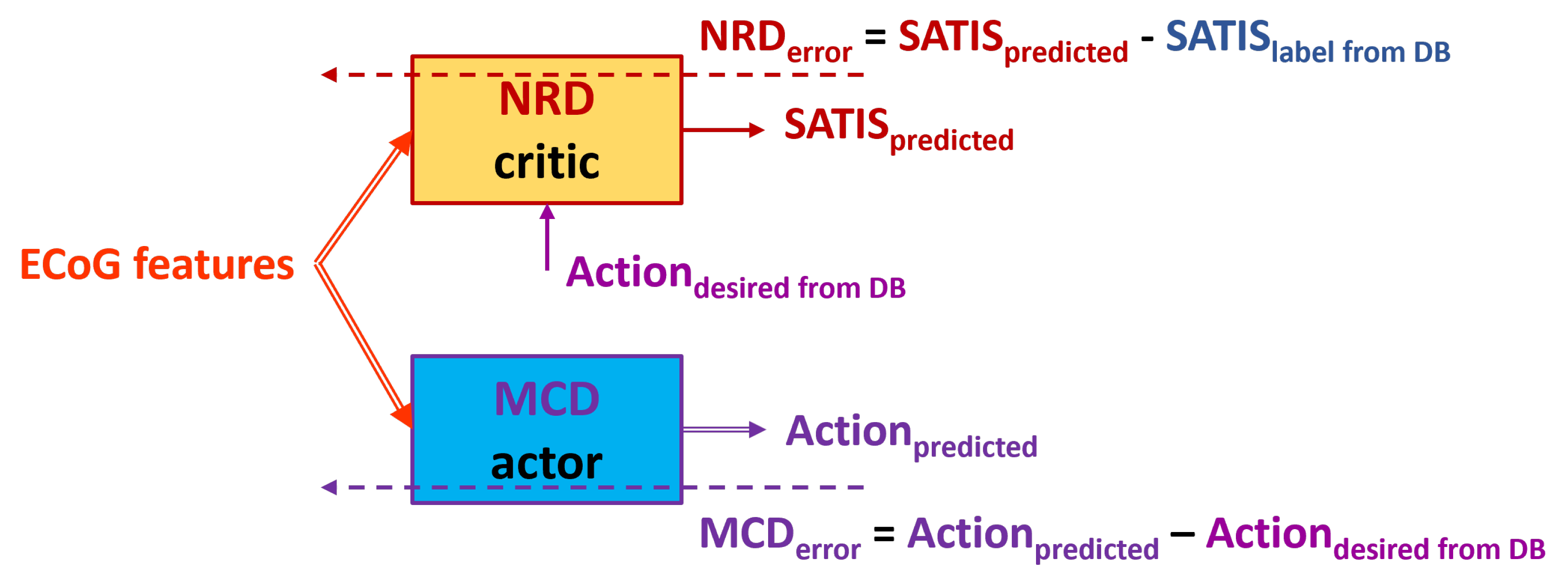
Figure 7.
Block diagram of the TA3. Dashed arrows represent training data and error while the solid once - the input and output data to/from MCD and NRD modules.
Figure 7.
Block diagram of the TA3. Dashed arrows represent training data and error while the solid once - the input and output data to/from MCD and NRD modules.
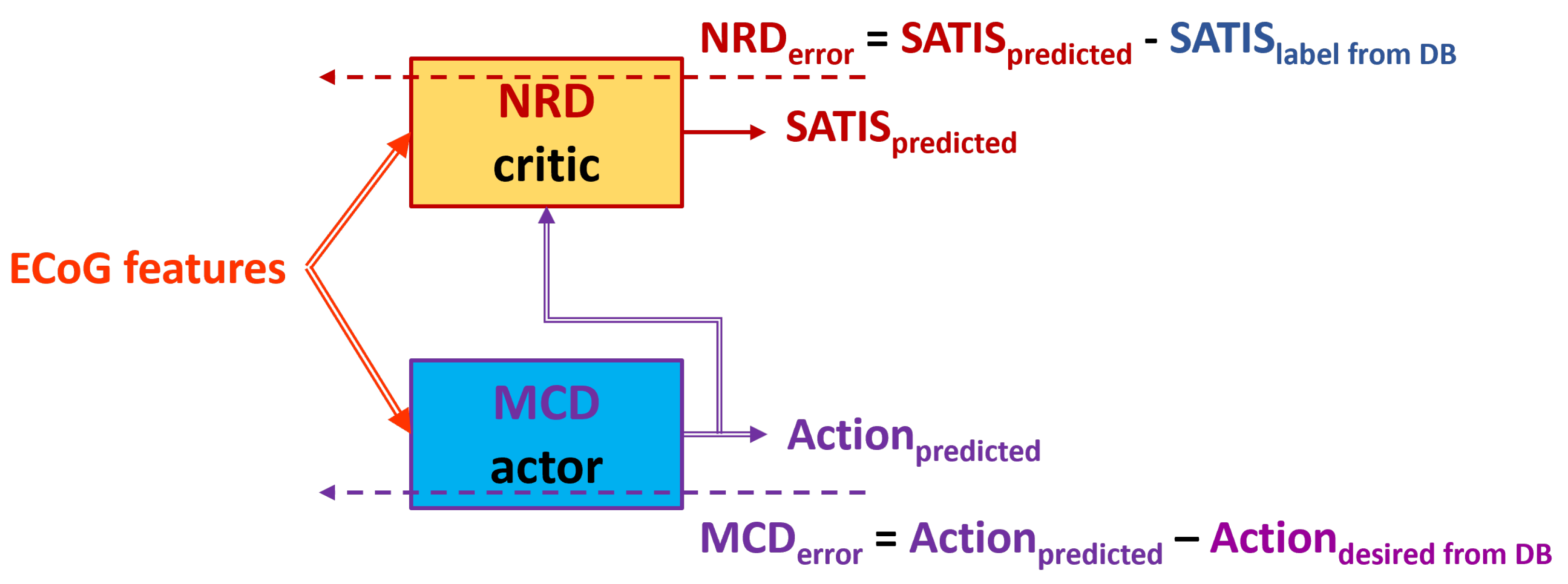
Figure 8.
Block diagram of the TA4. Dashed arrows represent training data and error while the solid once - the input and output data to/from MCD and NRD modules.
Figure 8.
Block diagram of the TA4. Dashed arrows represent training data and error while the solid once - the input and output data to/from MCD and NRD modules.
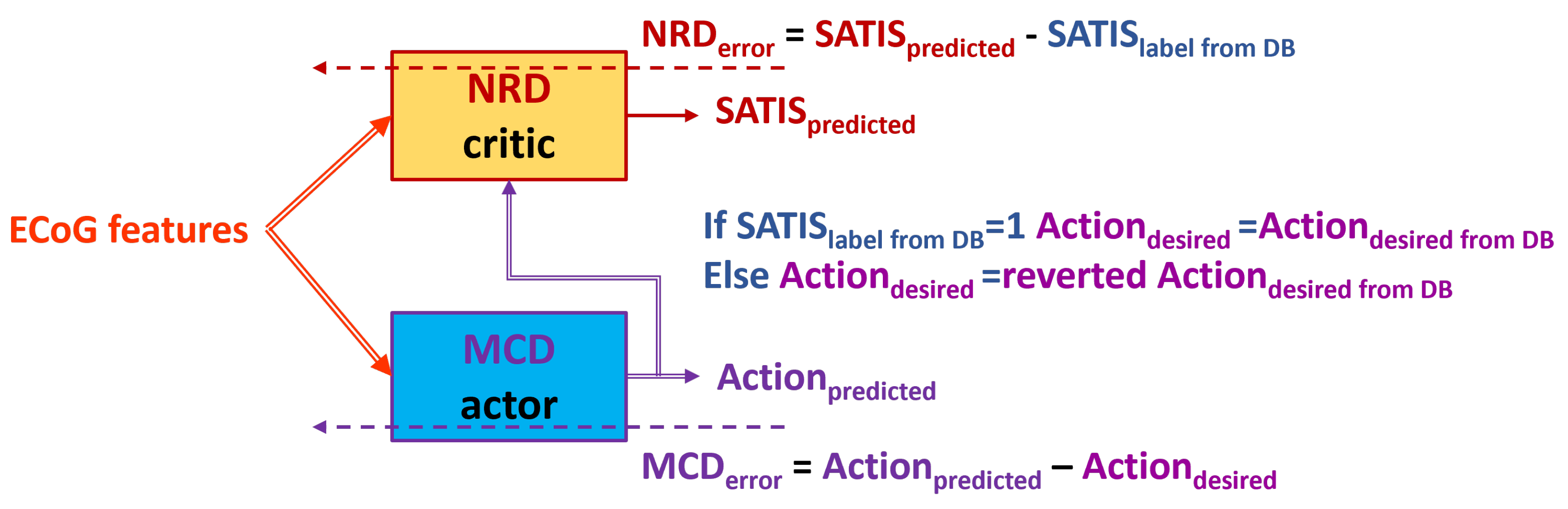
Figure 9.
Testing in TE1. The NRD uses known target movement of the avatar. Dashed arrow from NRD output denotes possible corrective feedback from NRD to the MCD output.
Figure 9.
Testing in TE1. The NRD uses known target movement of the avatar. Dashed arrow from NRD output denotes possible corrective feedback from NRD to the MCD output.
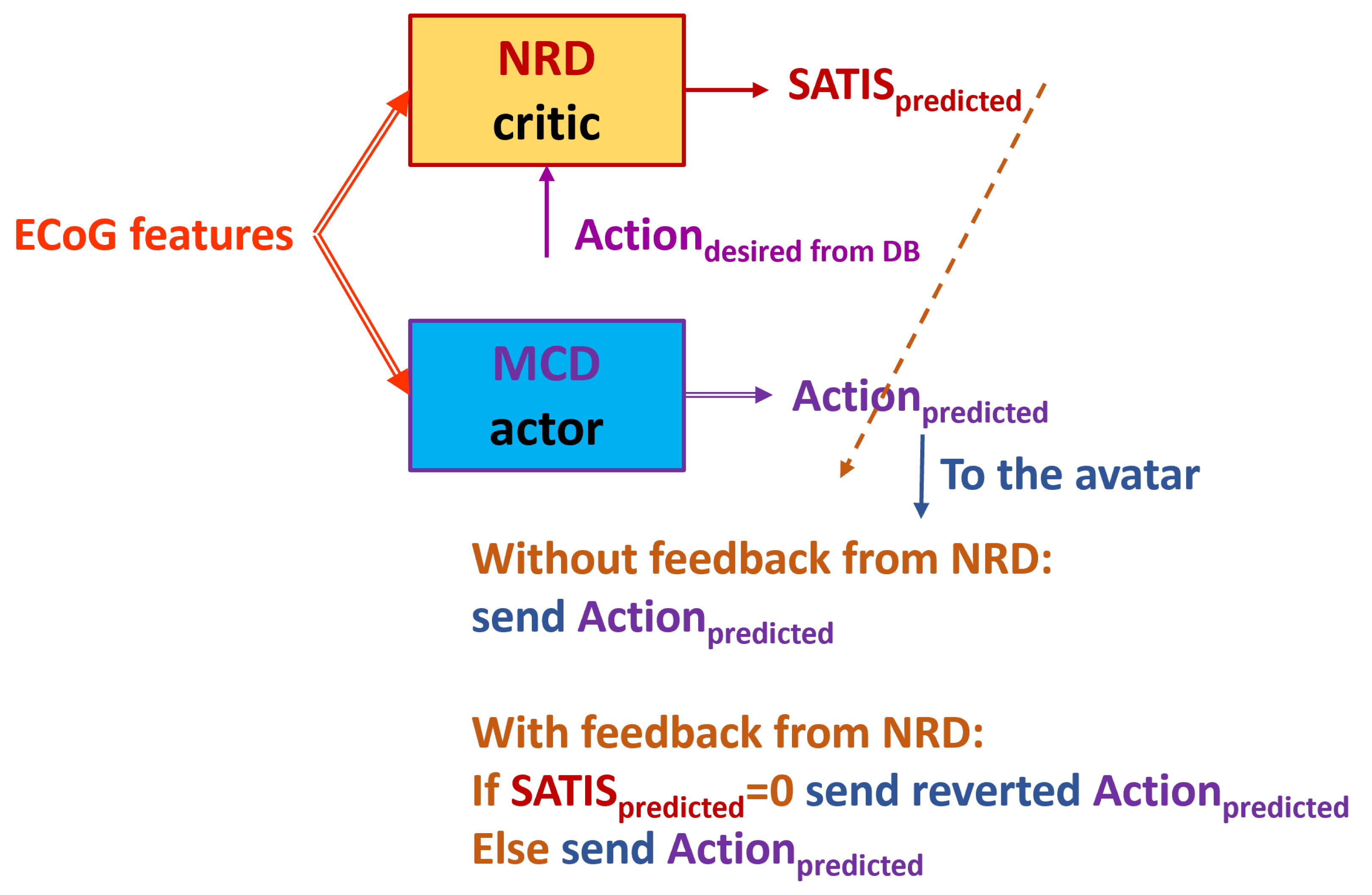
Figure 10.
Testing in TE2. The NRD uses predictions from the trained MCD. Dashed arrow from NRD output denotes possible corrective feedback from NRD to the MCD output.
Figure 10.
Testing in TE2. The NRD uses predictions from the trained MCD. Dashed arrow from NRD output denotes possible corrective feedback from NRD to the MCD output.
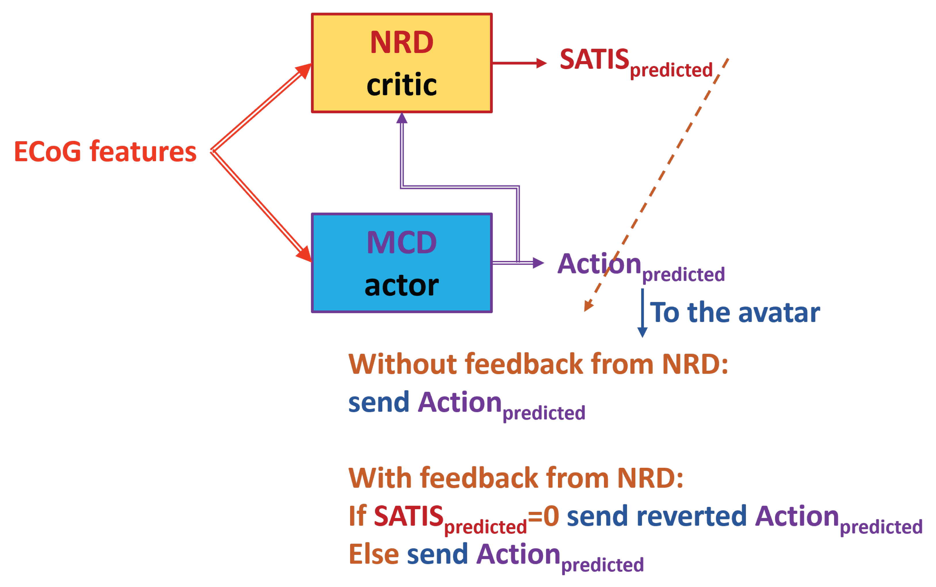

Table 1.
Terminology counterparts.
| Experiment | Reinforcement learning |
|---|---|
| patient | object |
| ECoG features | |
| MCD | actor |
| State | Action |
| NRD | critic |
| satisfaction | reinforcement signal |
Table 2.
Testing accuracy of NRD from TE1. The best results are underlined.
| Training approach | Metrics | Session 8 | Session 9 |
|---|---|---|---|
| TA1 | Balanced Accuracy | 0.7491 | 0.7616 |
| TA2 | Balanced Accuracy | 0.6474 | 0.5456 |
| TA1 | on | 0.4145 | 0.4924 |
| TA2 | on | 0.3643 | 0.1546 |
| TA1 | on | 0.9219 | 0.9610 |
| TA2 | on | 0.9491 | 0.9586 |
Table 3.
Testing accuracy of NRD from TE2. The best results are underlined.
| Training approach | Metrics | Session 8 | Session 9 |
|---|---|---|---|
| TA1 | Balanced Accuracy | 0.6279 | 0.5578 |
| TA2 | Balanced Accuracy | 0.5291 | 0.4967 |
| TA1 | on | 0.2796 | 0.1549 |
| TA2 | on | 0.1386 | 0.0627 |
| TA1 | on | 0.9177 | 0.9162 |
| TA2 | on | 0.9028 | 0.9304 |
Table 4.
Testing accuracy of NRD from TE3. The best results are underlined.
| Training approach | Metrics | Session 8 | Session 9 |
|---|---|---|---|
| TA3 | Balanced Accuracy | 0.5637 | 0.5501 |
| TA4 | Balanced Accuracy | 0.6787 | 0.6424 |
| TA3 | on | 0.1800 | 0.1391 |
| TA4 | on | 0.2761 | 0.2350 |
| TA3 | on | 0.8657 | 0.8793 |
| TA4 | on | 0.8532 | 0.9028 |
Table 5.
Testing accuracy of MCD from the (TE1) and (TE2) experiment. The best results are underlined.
Table 5.
Testing accuracy of MCD from the (TE1) and (TE2) experiment. The best results are underlined.
| Training approach | NRD feedback | Metrics | Session 8 | Session 9 |
|---|---|---|---|---|
| TA1 | YES | Balanced Accuracy | 0.8069 | 0.7593 |
| TA1 | NO | Balanced Accuracy | 0.8370 | 0.7699 |
| TA2 | YES | Balanced Accuracy | 0.8723 | 0.8715 |
| TA2 | NO | Balanced Accuracy | 0.8304 | 0.8251 |
| TA1 | YES | on | 0.8285 | 0.7879 |
| TA1 | NO | on | 0.8221 | 0.7393 |
| TA2 | YES | on | 0.8389 | 0.8589 |
| TA2 | NO | on | 0.8154 | 0.8086 |
| TA1 | YES | on | 0.7861 | 0.7272 |
| TA1 | NO | on | 0.8490 | 0.7973 |
| TA2 | YES | on | 0.8767 | 0.8886 |
| TA2 | NO | on | 0.8416 | 0.8415 |
Table 6.
Testing accuracy of MCD from TE3. The best results are underlined.
| Training approach | NRD feedback | Metrics | Session 8 | Session 9 |
|---|---|---|---|---|
| TA3 | YES | Balanced Accuracy | 0.7942 | 0.7691 |
| TA3 | NO | Balanced Accuracy | 0.8370 | 0.7699 |
| TA4 | YES | Balanced Accuracy | 0.8724 | 0.8800 |
| TA4 | NO | Balanced Accuracy | 0.8366 | 0.8403 |
| TA3 | YES | on | 0.7528 | 0.7363 |
| TA3 | NO | on | 0.8490 | 0.7973 |
| TA4 | YES | on | 0.8812 | 0.8945 |
| TA4 | NO | on | 0.8209 | 0.8273 |
| TA3 | YES | on | 0.8130 | 0.8047 |
| TA3 | NO | on | 0.8221 | 0.7393 |
| TA4 | YES | on | 0.8400 | 0.8693 |
| TA4 | NO | on | 0.8508 | 0.8536 |
Disclaimer/Publisher’s Note: The statements, opinions and data contained in all publications are solely those of the individual author(s) and contributor(s) and not of MDPI and/or the editor(s). MDPI and/or the editor(s) disclaim responsibility for any injury to people or property resulting from any ideas, methods, instructions or products referred to in the content. |
© 2025 by the authors. Licensee MDPI, Basel, Switzerland. This article is an open access article distributed under the terms and conditions of the Creative Commons Attribution (CC BY) license (http://creativecommons.org/licenses/by/4.0/).
Copyright: This open access article is published under a Creative Commons CC BY 4.0 license, which permit the free download, distribution, and reuse, provided that the author and preprint are cited in any reuse.


