
Submitted:
29 June 2025
Posted:
30 June 2025
You are already at the latest version
Abstract
The treatment of chronic wounds and pressure sores is an important challenge in the context of public health and the effectiveness of patient treatment. Therefore, new methods are being developed to reduce or, in extreme cases, to initiate and conduct the wound healing process. The article presents an innovative smart bandage, programmable using a smartphone, which generates small amplitude impulse vibrations. The communication between the smart bandage and the smartphone is realized using BLE. The possibility of programming the smart bandage allows for personalized therapy. Owing to the built-in MEMS sensor, the smart bandage makes it possible to monitor work during rehabilitation and implement an auto-calibration procedure. The flexible, azure mechanical structure of the dressing was made in 3D printing technology, thanks to which the solution is easy to implement and can be used together with traditional dressings to create hybrid ones. Miniature electronic circuits and actuators controlled by the PWM signal were designed as replaceable elements, thus the azure structure can be treated as single-use. The smart bandage containing 6 actuators presented in the article generates oscillations in the range from about 40 Hz to 190 Hz. The actuators were operated with the voltage of 1.65 V to reduce energy consumption. For comparison, the actuators were also operated with the nominal voltage of 3.17 V, as specified by the manufacturer.
Keywords:
Smart
; Mobile
; IoT
; Wearable
; Embedded system
; Wound healing
1. Introduction
Increasing treatment effectiveness is a socially relevant issue. Acceleration of the treatment process makes it possible to reduce its cost and the time of social exclusion. Society’s expectations concerning the availability of health technologies [1], including those that can be used at home, also increase. Therefore, it is important to produce new technologies as well as to reduce the costs of potential production or produce alternative, cheaper counterparts of the popular and hard-to-access solutions [2]. The development of wearable sensor technologies that can be produced using sewing machines [3] and smart textile biosensors [4] is in line with this concept. One of the social problems is the treatment of wounds, including chronic wounds and pressure sores. The risk group in which chronic wounds may occur includes people with metabolic diseases such as diabetes [5]. It is therefore estimated that in the world population about a billion people are in this risk group [6]. In this regard, in recent years, there has been a dynamic development of the concept of the so-called smart bandages. These are complex structures that make it possible to monitor some selected body functions or distribute drugs [7,8,9]. One of the applications of this type of solutions is wound monitoring using flexible breathable materials [10]. In turn, in the process of wound treatment, it is beneficial to use cheap single-use solutions [11,12]. Wound healing can also be accelerated by using gel dressings [13], which make it possible to adjust pressure in the wound [14], or electroactive dressings [15]. The dynamic development of the smart bandage concept is supported by using 3D printing technology. In this respect, research is conducted on the application of, among others, hydrogels [16,17]. 3D printing also allows for the production of complex and electronically controlled structures which use microneedles to provide drugs [18]. Extrusion-based printing methods are also used to produce topical skin applications [19]. Currently, smart bandages are complex systems that allow for data transmission and wound monitoring via smartphones [20,21,22]. In the context of treating wounds, including chronic ones, it is worth mentioning the use of vibrations of various frequencies and amplitudes. Vibration wound therapy can accelerate the foot wound healing process [23]. Moreover, the use of the vibration platform makes it possible to accelerate diabetic neuropathy foot ulcer healing in patients diagnosed with diabetes [24].
The article presents the smart bandage system using vibration actuators. When designing the system, the following requirements were taken into account: low production costs (standard electronic components), the possibility of using single-use and universally accessible components as well as cheap manufacturing technology (3D printing). In addition, the solution makes it possible to scale the wearable part. In the present article, it was assumed that oscillators would generate vibrations at a similar level, so that the distribution of oscillations within the smart bandage would be homogeneous.
2. Materials and Methods
The solution presented in the article - Skeletal Smart Bandage (SSB) has been designed as a modular system, which allows for scaling its functionality and integrating modules in various configurations. SSB is an active system that generates vibrations. When the vibrations are placed within the wound area, they can increase blood supply and, in this way, may have a positive effect on accelerating the healing process.
The first of the system modules is a flexible azure structure (FAS), presented in Figure 1, which is the SSB mechanical base. The azure structure does not block the access of air to the surface on which it is placed, owing to which it can be combined with classic dressings creating a hybrid structure. FAS is made in 3D printing technology, which allows for the quick modification of its mechanical structure and the adjustment of the shape to individual needs, i.e., personalization. FAS modular skeletal structure makes it possible to attach electronic components included in SSB. FAS contains slots in which the actuators (mini-vibration engines) and the sensor (accelerometer) are placed, which is described in more detail later in the article. This concept of the azure structure allows it to be used as a replaceable element, which in the case of dressings is particularly important. Figure 1 shows the azure structure in the shape of a hexagon with a side length of 45 mm and a thickness of 0.5 mm, designed for 6 actuators (E1-E6). The azure structure also includes a slot for the accelerometer, which is located in the middle of the structure and is marked as C. FAS also has holders (FAS Holder), which can be used for SSB attachment, for example, to a traditional dressing, using an adhesive tape or standard clips.
MT24 miniature vibration engines with a diameter of 10 mm and a height of 3.7 mm were used as vibration generators in SSB. Similar actuators are used for quiet notifications in mobile devices. According to the SSB concept, the number of vibration actuators used can be variable and selected depending on the needs, which allows for scaling the smart bandage structure. Each of the actuators was locked in a designed housing and then placed in the appropriate mounting sockets in the azure structure. The view of the miniature MT24 actuators is presented in Figure 2a. On the other hand, the vibrating engine placed in the housing and the enlarged fragment of the azure structure made in 3D printing technology are shown in Figure 2b.
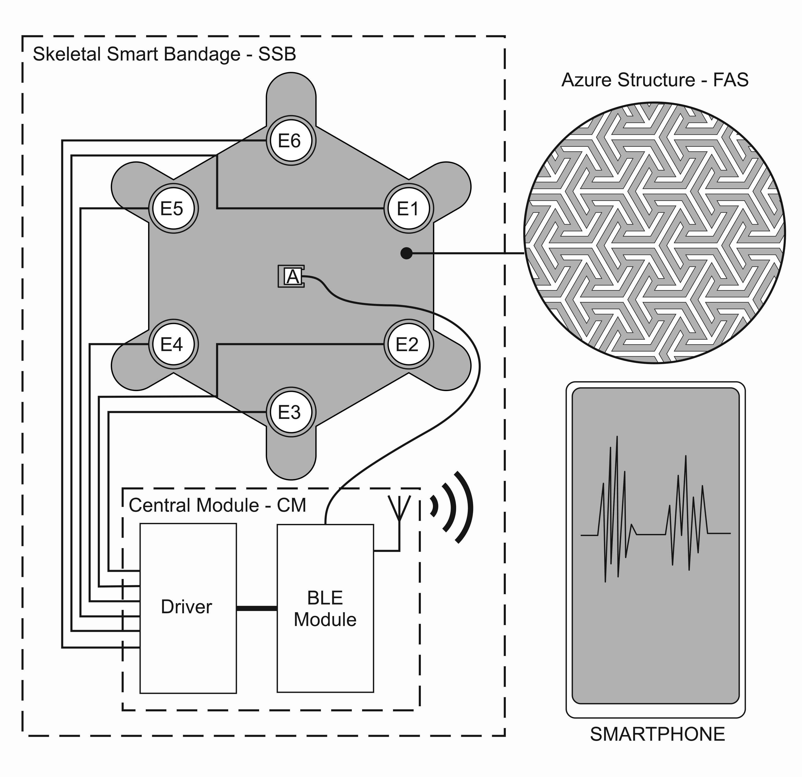
Another SSB function block is the programmable central module (CM), which is a built-in smart bandage system. CM performs the following functions: controller for the actuators (MT24) and the measuring system for the accelerometer. Wiring and electronics are disassembled and can be used with another azure structure. The central module was implemented in the form of reduced architecture [25,26,27,28], which means that the microcontroller was built into the BC832 radio module [29] with an implemented chip in SOC technology (System on Chip) - NRF52832 [30]. Vibrating engines E1 to E6 are attached to CM via transistor keys (DRIVER), which are also output buffers of the BC832 module. An ultra-low power acceleration sensor - BMA400 [31] is also attached to the central module. It makes it possible to monitor the work cycles of individual engines and to perform the calibration procedure. Communication between the NRF52832 chipset and the BMA400 sensor was implemented using the I2C bus. The accelerometer, used for both performing measurements and carrying out the actuator calibration procedure, was placed in the central slot marked as C. The architecture of electronic circuits is presented in Figure 3.
The measurement data from the accelerometer were transmitted by radio (BLE - Bluetooth low energy), whereas data acquisition was carried out on a smartphone. An application has also been implemented on the smartphone that allows for controlling SSB operating modes.
The diagram of vibration actuators and electronics implemented in SSB is presented in Figure 4. Figure 5, on the other hand, presents a miniature PCB containing BMA400 and placed in the central slot of the azure structure.
2.2. Smart Bandage Mobile Application
The presented system is part of the concept of the Internet of Things (IoT). By using an energy -saving radio communication interface (BLE), it was possible to implement two-way communication between control electronics and mobile devices. In home applications, this type of functionalities has become standard. However, in clinical applications, they create new therapeutic possibilities. The proposed system architecture allows for wide modelling of the functionality of the solution. In practice, it means the possibility of individual work of a smart bandage controller, monitoring therapeutic cycles from the mobile device or modification of the software controlling the smart bandage from a smartphone.
Already at the stage of performed laboratory tests, simple profiles controlling the actuators and auto-calibration process were implemented on the smart bandage electronics side. In practice, it is possible to implement various control profiles in the memory of controllers that can be selected for healing specific types of wounds. As mentioned before, the choice of control profiles can be implemented from the smartphone level or using a switch built into the bandage controller. An important functionality implemented in the mobile software is the ability to develop your own power control schemes for each actuator and the time of their operation. This makes it possible to upload personalized therapeutic profiles, but practical applications of this functionality require further research. Screenshots of the smart bandage mobile system application are presented in Figure 6.
2.2. Calibration Procedure of Actuators
In order to equalize the amplitude of vibrations generated by individual smart bandage vibration actuators, calibration is carried out based on accelerometric measurements. Individual actuators are controlled using a PWM signal. In the calibration procedure, it was assumed that the change in PWM affects a rectilinear increase in generated vibrations. During calibration, each vibration actuator is activated individually, the others are turned off. When the actuator is working, the accelerometer placed in a central bandage pocket carries out measurements with sampling with ODR (Output Data Rate) of 400 Hz. The calibration procedure begins with a 10 % PWM filling, and then the filling increases every 10 % until 100 % is reached. The first 100 measuring points from the accelerometer are rejected, which corresponds to 250 ms. This time allows the engine to start and stabilize its speed. The accelerometer in the FIFO queue aggregates data into packages, where each data package contains 25 measuring points. A series of 50 packages of measurement data is sent to the microcontroller, where a signal constant component is removed. Then the absolute value is calculated from the variable component of each measuring point.
In the next stage, the maximum value is selected from the processed data from each FIFO package. Therefore, 50 points are obtained, from which the mean value is calculated. This procedure is used for the measurement data from each actuator with all PWM values. It makes it possible to determine the real characteristics of the averaged oscillation amplitudes (AOA) individually for each actuator. After the measurement cycle and data processing, from the characteristics received for all actuators, the minimum value of AOA is determined with 100 % filling and the maximum value of AOA when PWM filling is 10 %. These two values allow for determining straight calibration lines for actuators.
The designated straight calibration line contains the expected values of the averaged oscillation amplitudes (AOAs) for the assumed values of the PWM signal filling, which makes it possible to equalize the operation of individual actuators. Then, in the iterative process, the rectangular wave filling is changed until the value of the expected oscillation amplitude is achieved for a specific, assumed filling (from 10 % to 100 %), and this value for each actuator is saved in the microcontroller memory. The described calibration procedure can be used for various types of actuators and with different power voltage values. Calibration can be made separately for each of the accelerator axis, and then each component can be analysed independently. It is also possible to calibrate all the axes at the same time, but then the resultant vector of acceleration ar should be previously determined according to the Formula (1):
where ax, ay, az – components of acceleration, along the x, y and z axes and from the accelerometer.
Miniature vibration actuators can differ significantly in terms of parameters, e.g., vibration amplitude in individual axes, which is presented in Figure 7a–c. For this reason, it is more beneficial to calculate the resultant vector, which was used in the measuring procedure. An example of the impact of the calibration procedure on the equalization of oscillations is presented in Figure 7d.
Figure 7d also shows the impact of calibration performed relative to the resultant vector on individual axes. The characteristics of oscillations of individual vibration actuators before calibration (Figure 7d) show a relatively large variety of amplitudes - the weakest actuator generated oscillations that were about 65 % weaker than those generated by the strongest one. The use of the calibration procedure makes it possible to reduce the diversity of oscillations to approx. 30 %. The calibration procedure also allows for testing the possibility of controlling the vibration amplitudes of individual actuators and selecting subpar systems, e.g., of lower quality or with a greater extent of wear. As mentioned earlier, the smart bandage has a modular structure and allows for quick replacement of the main components, including actuators. It can be observed in Figure 7d that after the calibration process, the amplitude of the resultant acceleration vector ar of one of the actuators has a lower value (marked with a red rectangle). This may indicate, for example, its lower production quality. In the case of other actuators, the equalization of oscillation amplitudes is visible.
3. Results and Discussion
The developed smart bandage system was tested in several configurations. First, the smart bandage operation was verified using various voltages of actuators. To this end, 10 actuators were selected, whose operation was stabilized for 10 s, and then the oscillations they generated were measured. Figure 8 shows the results of current measurements of individual oscillators at reduced 1.65 V power supply and nominal supply of 3.17 V. In both cases, the diversity of results was checked, i.e., the ratio of standard deviation to the mean value was calculated. In the case of nominal power (3.17 V), the diversity coefficient was 10.6 %, whereas with the lower power supply of 1.65 V, the diversity slightly increased and amounted to 11.6 %. In both cases, the obtained value of the diversity coefficient indicates a small scatter of results among individual actuators.
One of the research goals was to verify the possibility of saving energy in the designed smart bandage system. Taking into consideration the fact that the energy demand of the system is determined mainly by the actuators, it was verified how effective their operation would be after a relatively high reduction in the supply voltage in relation to the nominal value. The implementation of this type of testing is also interesting in the aspect of controlling the actuators using a voltage change. The results of measurements of the smart bandage operation at the reduced supply voltage of 1.65 V and nominal supply voltage of 3.17 V (3V) are presented and discussed further in the article.
Another analysed aspect was the fact that wounds may appear in different places in the body and can be of different sizes, so the dressing should be adapted to the geometry of the wound surface. Flat wounds can occur e.g., on the back or stomach. We deal with convex surfaces e.g., in the case of limb or head wounds. Therefore, smart bandage tests were planned on two types of surfaces: flat and convex. The PE technical foam was used to model the flat surface. In turn, the convex surface was created using 3D printing. The forearm model was generated, and then it was printed using TPU (Thermoplastic polyurethane) material. The view of the phantom forearm is presented in Figure 9. The selection of materials was aimed at simulating the working conditions of a smart bandage to its operation on the human body.
As part of the conducted research, an azure structure printed from three different materials, i.e., Nylon (Polyamide), PP (Polypropylene) and TPU, was also verified. In this way, structures of various stiffness were obtained. Then, the research procedure took into account the simultaneous impact of the change in the supply voltage of the actuators, the material used for azure structure, oscillator calibration and surface geometry, on the smart bandage operation. In all measurements, the actuators were activated sequentially for 2 s with a 2 s interval.
Figure 10 shows the impact of the calibration procedure and the material from which the smart bandage azure structure (FAS) was made when performing tests on the flat surface (PE technical foam) and at the reduced power supply of actuators (1.65 V). It can be observed in the chart that the calibration procedure effectively equalizes the vibrations of actuators in the case of the structure made of Nylon and PP. However, with the structure made of TPU (the most flexible of the tested ones), a significant diversity of amplitudes for individual actuators is visible, despite the calibration used. Thus, in the case of a flexible azure structure, a significant reduction in the supply voltage of actuators to reduce energy consumption makes the calibration rather ineffective.
In turn, Figure 11 also takes into account the surface curvature. Placing actuators, with reduced supply voltage, on the convex surface means that calibration is inefficient for each of the materials used. The smallest diversity of oscillation amplitudes after calibration is noticeable for the stiffest structure, i.e., made of Nylon. Therefore, a significant reduction in the power supply of actuators when using the smart bandage on convex surfaces can lead to heterogeneous vibration distribution within its area. Therefore, further tests were performed, in which nominal supply voltage was used, i.e., 3.17 V. The results presented in Figure 12 indicate that increasing the supply voltage value positively affects the homogeneity of the generation of oscillations within AS. In the case of each of the materials used, equalization of the oscillation amplitudes of individual actuators after calibration is visible.
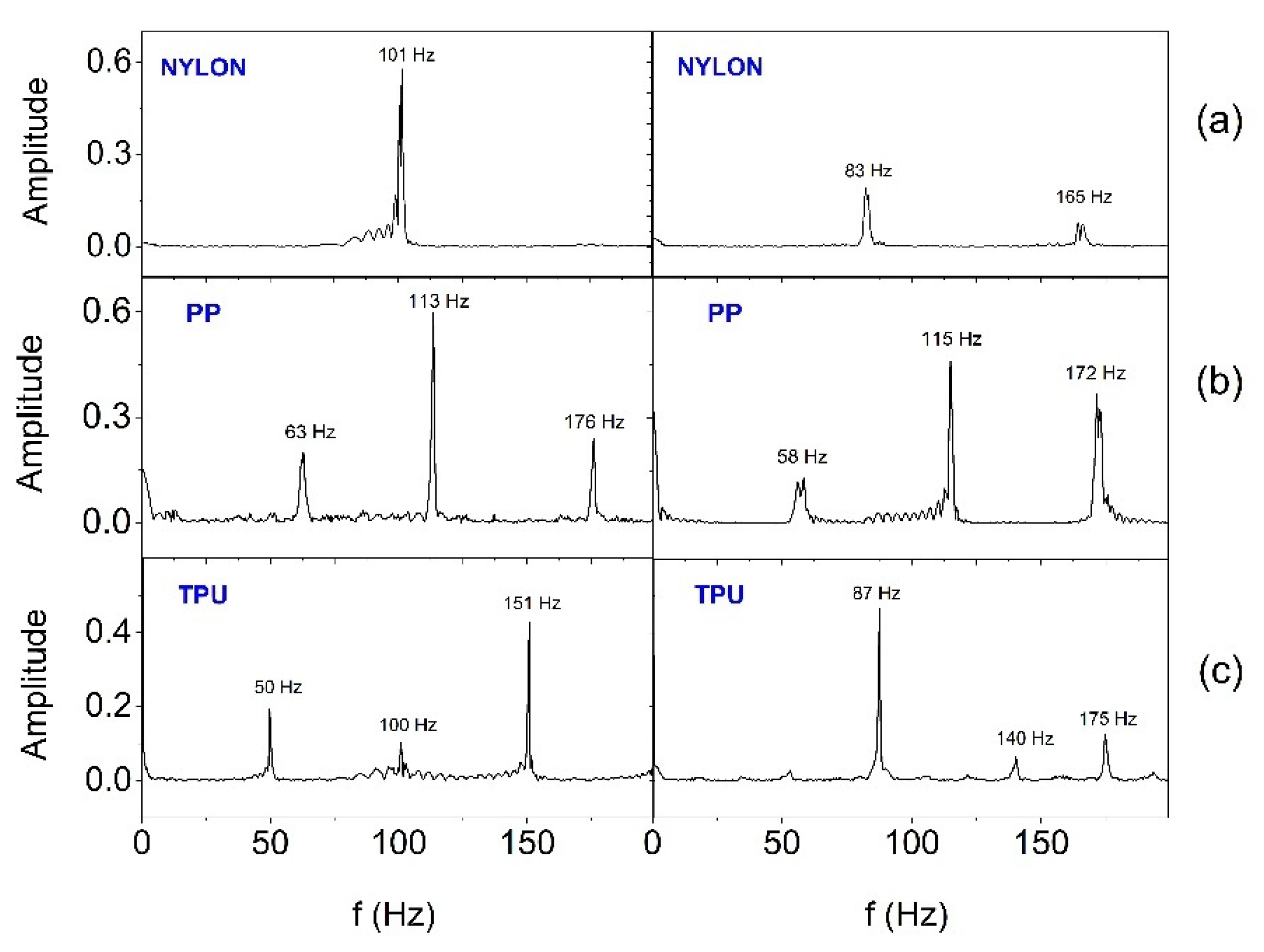
In order to estimate the frequency range in which SSB generates vibrations, the Fast Fourier Transform (FFT) analysis was performed. Figure 13 and Figure 14 show FFT results for selected two (E2 and E3) out of six actuators working in the smart bandage, appropriately placed on the flat surface and powered with 1.65 V (Figure 13) and placed on the forearm phantom and powered with nominal voltage of 3.17 V (Figure 14), respectively. In all cases, the operation of actuators was recorded after prior calibration. The analyses performed indicate that the frequency of vibrations changes in the range from around 40-50 Hz to around 180-190 Hz. When the smart bandage is placed on the flat surface, more characteristic oscillation frequencies (Figure 14) are generated than when placed on the convex surface (Figure 13). Most likely, when the smart bandage structure bends, mechanical vibrations are filtered within FAS. Differentiation of the quantity and frequency values of individual peaks, observed for the same oscillators placed in different FASs, is unlikely to result from the properties of the material from which the structure was printed, but it may be the result of transferring the actuators into the next structure during the research. This situation indicates that the mechanical system (azure structure - actuator) is relatively complex, if only because of the possibility of clearance fit on matching connections (press fits). The research suggests that satisfactory results can be obtained despite the use of simple mechanic solutions. The results indicate that regardless of the shape of the surface on which the smart bandage is placed, it generates vibrations in the frequency range that is used in vibration therapies. Studies carried out on rats have shown that vibrations with a frequency of 45 Hz can promote the healing process of stage II pressure ulcers [32]. It should be emphasized that current studies on the treatment of chronic wounds in humans (e.g., Diabetic Neuropathic Foot Ulcer) indicate the effectiveness of vibration therapy in the frequency range of about 50 Hz [33].
4. Conclusions
The article presents the concept of the smart bandage system made in the widely available 3D printing technology and integrated with high technologies. Despite the simple mechanical structure, which, among others, translates into low costs of producing the hardware base, high functionality has been achieved. It was possible thanks to the connection of the system with the concept of the Internet of Things (IoT). As a result, the presented system is characterized by the possibility of personalizing therapy as well as controlling, monitoring and programming the smart bandage from mobile devices. The modular design of the smart bandage increases its functionality and versatility. The frequency range it generates coincides with the frequencies used in vibrotherapy. In addition, the universality of the solution is supported by the possibility of using various materials for printing the smart bandage azure structure. Although there were differences in the work of individual smart bandage configurations, including different power supply levels of actuators (1.65V and 3.17V), it has been shown that the solution can be potentially used for the treatment of wounds on both flat and convex surfaces.
Author Contributions
Conceptualization, M.A. Janik and P. Janik.; methodology, M.A. Janik.; software, M. Pielka, M.A. Janik, P. Janik; validation, M.A. Janik and P.Janik.; formal analysis, M.A. Janik; investigation, M.A. Janik, M. Pielka, P. Janik, P. Kovalchuk, M. Mierzwa; data curation, M.A. Janik and M. Pielka; writing—original draft preparation, M.A. Janik and P.Janik.; writing—review and editing, M.A. Janik, P.Janik. and M. Mierzwa; visualization, M.A. Janik, P.Janik and M. Pielka.; supervision, M.A. Janik;
All authors have read and agreed to the published version of the manuscript.
Funding
This research received no external funding.
Institutional Review Board Statement
Not applicable.
Informed Consent Statement
Not applicable.
Data Availability Statement
Not applicable.
Conflicts of Interest
The authors declare no conflicts of interest.
References
- Jagan, S. M.; Su, B. Ch.; Seung-Boo, J.; Jong-Woong, K. Electronic textiles: New age of wearable technology for healthcare and fitness solutions. Materials Today Bio 2023, 19, 100565. [Google Scholar] [CrossRef]
- Knulst, A.J.; Berger, S.; van den Boom, J.; Bosch, I.; Nicolai, N.; Maharjan, S.; Raaijmakers, E.; Tsai, Ch-L, van de Weerd; Dankelman, J.; Diehl, J-C. The WOCA negative pressure wound therapy device designed for low resource settings. HardwareX 2025, 21, e00620. [Google Scholar] [CrossRef] [PubMed]
- Piper, A.; Öberg Månsson, I.; Khaliliazar, S.; Landin, R.; Hamedi, M.M. A disposable, wearable, flexible, stitched textile electrochemical biosensing platform. Biosensors and Bioelectronics 2021, 191, 113604. [Google Scholar] [CrossRef] [PubMed]
- Khan, A.; Haque, M.N.; Kabiraz, D.Ch.; Yeasin, A.; Rashid, H.A.; Sarker, A. Ch.; Hossain, G. A review on advanced nanocomposites materials based smart textile biosensor for healthcare monitoring from human sweat. Sensors & Actuators: A. Physical 2023, 350, 114093. [Google Scholar] [CrossRef]
- Kolipaka, T.; Pandey, G.; Abraham, N.; Srinivasarao, D.A.; Raghuvanshi, R.S.; Rajinikanth, P.S.; Tickoo, V.; Srivastava, S. Stimuli-responsive polysaccharide-based smart hydrogels for diabetic wound healing: Design aspects, preparation methods and regulatory perspectives. Carbohydrate Polymers 2024, 324, 121537. [Google Scholar] [CrossRef]
- Garraud, O.; Hozzein, W.N.; Badr, G. Wound healing: time to look for intelligent, ‘natural’ immunological approaches? BMC Immunol 2017, 18 (Suppl 1), 23. [Google Scholar] [CrossRef]
- Pang, Q.; Yang, F.; Jiang, Z.; Wu, K.; Hou, R.; Zhu, Y. Smart wound dressing for advanced wound management: Real-time monitoring and on-demand treatment. Materials & Design 2023, 229, 111917. [Google Scholar] [CrossRef]
- Yang, Ch.; Yang, Ch.; Chen, Y.; Liu, J.; Liu, Z.; Chen, H.-J. The trends in wound management: Sensing, therapeutic treatment, and “theranostics”. Journal of Science: Advanced Materials and Devices 2023, 8, 100619. [Google Scholar] [CrossRef]
- Youssef, K.; Ullah, A.; Rezai, P.; Hasan, A.; Amirfazli, A. Recent advances in biosensors for real time monitoring of pH, temperature, and oxygen in chronic wounds. Materials Today Bio 2023, 22, 100764. [Google Scholar] [CrossRef]
- Xu, L.; Ding, L.; Sun, Y.; Zhang, T.; Zhu, Y.; Yan, B.; Yang, M.; Ramakrishna, S.; Zhang, J.; Long, Y.-Z. Stretchable, flexible and breathable polylactic acid/polyvinyl pyrrolidone bandage based on Kirigami for wounds monitoring and treatment. International Journal of Biological Macromolecules 2023, 237, 124204. [Google Scholar] [CrossRef]
- Pal, A.; Goswami, D.; Cuellar, H.E.; Castro, B.; Kuang, S.; Martinez, R.V. Early detection and monitoring of chronic wounds using low-cost, omniphobic paper-based smart bandages. Biosensors and Bioelectronics 2018, 117, 696–705. [Google Scholar] [CrossRef] [PubMed]
- Sani, E.S.; et al. A stretchable wireless wearable bioelectronic system for multiplexed monitoring and combination treatment of infected chronic wounds. Sci. Adv. 2023, 9, eadf7388. [Google Scholar] [CrossRef] [PubMed]
- Vithalani, H.; Dave, H.; Singh, H.; Sharma, D.; Navale, A.; Dhanka, M. Mechanically robust, mouldable, dynamically crosslinked hydrogel flap with multiple functionalities for accelerated deep skin wound healing. Biomaterials Advances 2025, 169, 214195. [Google Scholar] [CrossRef] [PubMed]
- Wang, J.; Zhao, Ch.; Yang, P.; He, H.; Yang, Y.; Lan, Z.; Guo, W.; Qin, Y.; Zhang, Q.; Li, S. A multifunctional electronic dressing with textile-like structure for wound pressure monitoring and treatment. Journal of Colloid and Interface Science, 2025, 679, 737–747. [Google Scholar] [CrossRef]
- Chen, W.; Wei, Y.; Chang, J.; Hui, Y.; Ye, J.; Weng, G.; Li, M.; Wang, Y.; Wum, Q. Electrostimulation combined with biodegradable electroactive oriented nanofiber polycaprolactone/gelatin/carbon nanotube to accelerate wound healing. Materials Today Bio 2025, 31, 101490. [Google Scholar] [CrossRef]
- Tsegay, F.; Elsherif, M.; Butt, H. Smart 3D Printed Hydrogel Skin Wound Bandages: A Review. Polymers (Basel) 2022, 14, 1012. [Google Scholar] [CrossRef]
- Wang, Y.; Wang, Z.; Lu, W.; Hu, Y. Review on chitosan-based antibacterial hydrogels: Preparation, mechanisms, and applications. International Journal of Biological Macromolecules 2025, 255, 128080. [Google Scholar] [CrossRef]
- Derakhshandeh, H.; Aghabaglou, F.; McCarthy, A.; Mostafavi, A.; Wiseman, C.; Bonick, Z.; Ghanavati, I.; Harris, S.; Kreikemeier-Bower, C.; MousaviBasri, S.M.; Rosenbohm, J.; Yang, R.; Mostafalu, P.; Orgill, D.; Tamayol, A. A Wirelessly Controlled Smart Bandage with 3D-Printed Miniaturized Needle Arrays. Adv. Funct. Mater. 2020, 30, 1905544. [Google Scholar] [CrossRef]
- Santos de Oliveira, R.; Fantaus, S.S.; Guillot, A.J.; Melero, A. 3D-Printed Products for Topical Skin Applications: From Personalized Dressings to Drug Delivery. Pharmaceutics 2021, 13, 1946. [Google Scholar] [CrossRef]
- Yu, M.; Yi, Ch.; Lin, S.; Ye, H.; Xue, J.; Yin, J.; Zhong, R.; Yao, H.; Liao, H.; Zhang, Y.; Yang, J.; Guo, Y.; Song, X-J. ; Ye, T.T. e-Bandage: Exploiting Smartphone as a Therapeutic Device for Cutaneous Wound Treatment. Adv. Intell. Syst. 2024, 6, 2300494. [Google Scholar] [CrossRef]
- Liu, Z.; Liu, J.; Sun, T.; Zeng, D.; Yang, Ch.; Wang, H.; Yang, Ch.; Guo, J.; Wu, Q.; Chen, H.-J.; Xie, X. Integrated Multiplex Sensing Bandage for In Situ Monitoring of Early Infected Wounds. ACS Sensors 2021, 6, 3112–3124. [Google Scholar] [CrossRef] [PubMed]
- Heck, I.; Lu, W.; Wang, Z.; Zhang, X.; Adak, T.; Cu, T.; Crumley, C.; Zhang, Y.; Wang, X.S. Wireless Pressure-Sensor-Integrated Smart Bandage for the Management of Diabetic Foot Ulcers, Adv. Mater. Technol. 2023, 8, 2200821. [Google Scholar] [CrossRef]
- Yu, C.O. ; Leung, K,S,; Jiang J.L.; Wang T.B.; Chow S.K.; Cheung W.H. Low-Magnitude High-Frequency Vibration Accelerated the Foot Wound Healing of n5-streptozotocin-induced Diabetic Rats by Enhancing Glucose Transporter 4 and Blood Microcirculation. Sci Rep. 2017, 7, 11631. [Google Scholar] [CrossRef] [PubMed]
- Syabariyah, S.; Nurachmah, E.; Widjojo, B.D.; Prasetyo, S.; Sanada, H.; Irianto; Nakagami, G. ; Suriadi; Kardiatun, T.; Hisan, U.K. The Effect of Vibration on the Acceleration of Wound Healing of Diabetic Neuropathic Foot Ulcer: A Prospective Experimental Study on Human Patients. Healthcare 2023, 11, 191. [Google Scholar] [CrossRef]
- Janik, P.; Pielka, M.; Janik, M.A.; Wróbel, Z. Respiratory monitoring system using Bluetooth Low Energy. Sensors and Actuators A: Physical. 2019, 286, 152–162. [Google Scholar] [CrossRef]
- Janik, P.; Janik, M.A.; Pielka, M. Power saving by a smart breath sensor working in non-connectable advertising mode. Sensors and Actuators A: Physical 2020, 315, 112324. [Google Scholar] [CrossRef]
- Janik, P.; Janik, M.A.; Pielka, M. Monitoring Breathing and Heart Rate Using Episodic Broadcast Data Transmission. Sensors (Basel) 2022, 22, 6019. [Google Scholar] [CrossRef] [PubMed] [PubMed Central]
- Pielka, M.; Janik, P.; Janik, M.A.; Wróbel, Z. Adaptive Data Transmission Algorithm for the System of Inertial Sensors for Hand Movement Acquisition. Sensors 2022, 22, 9866. [Google Scholar] [CrossRef]
- Bluetooth Low Energy (BLE) 5 Micro Module BC832, Ver 2.02, Fanstel Corp., Nov. 2020, www.fanstel.com.
- nRF52832 Product Specification v1.9, 2023 Nordic Semiconductor ASA., www.nordicsemi.com.
- BMA400 3-axes ultra-low power accelerometer. Doc. Rev. 2.2, January 2025. https://www.bosch-sensortec.com/products/motion-sensors/accelerometers/bma400/.
- Wano,N. ; Sanguanrungsirikul, S.; Keelawat, S.; Somboonwong, J. The effects of whole-body vibration on wound healing in a mouse pressure ulcer model. Heliyon 2021, 7, e06893. [Google Scholar] [CrossRef]
- Saragih, I.D.; Susanto, H.; Lin, H.-Ch.; Lee, B.-O. Vibration therapy for patients with hard-to-heal wounds: A systematic review and meta-analysis of experimental studies. Journal of Tissue Viability 2025, 34, 100852. [Google Scholar] [CrossRef]
Figure 1.
Azure bandage structure.
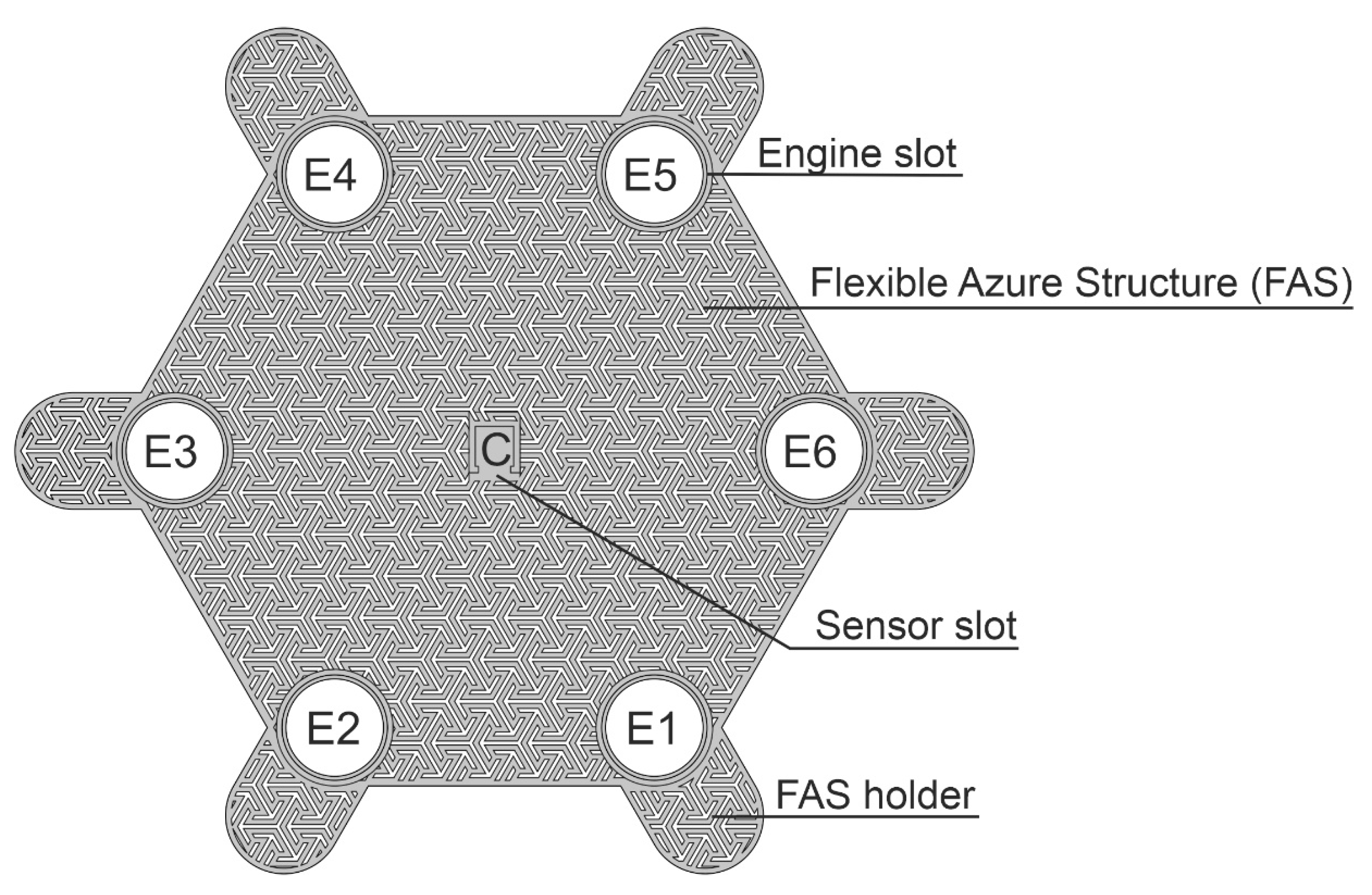
Figure 2.
Images of : (a) vibrating engine (actuator), (b) printed housing of the MT24 vibrating engine.
Figure 2.
Images of : (a) vibrating engine (actuator), (b) printed housing of the MT24 vibrating engine.
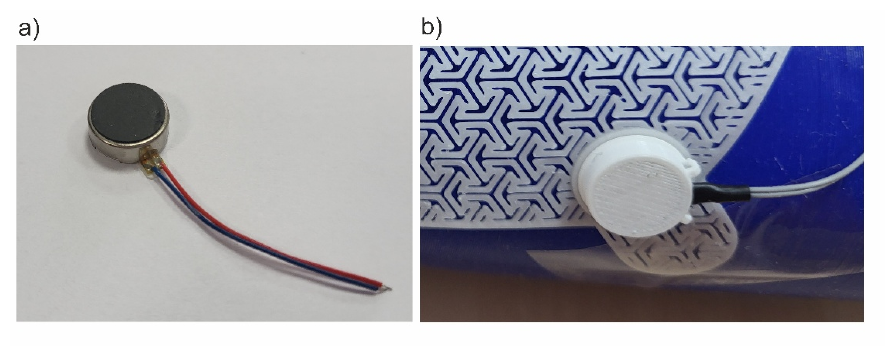
Figure 3.
The architecture of central module (CM, controller).
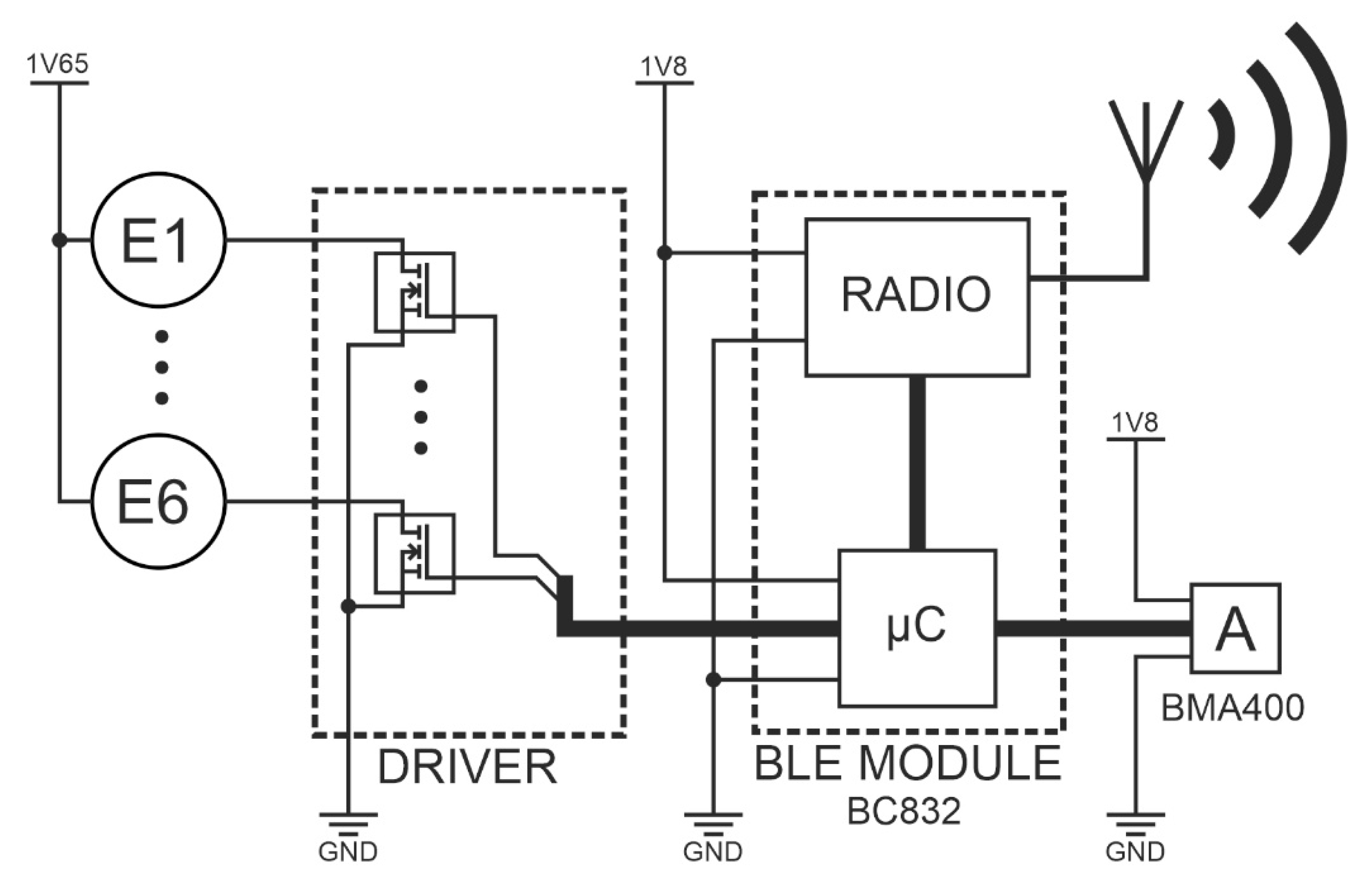
Figure 4.
System components: Skeletal Smart Bandage and smartphone.
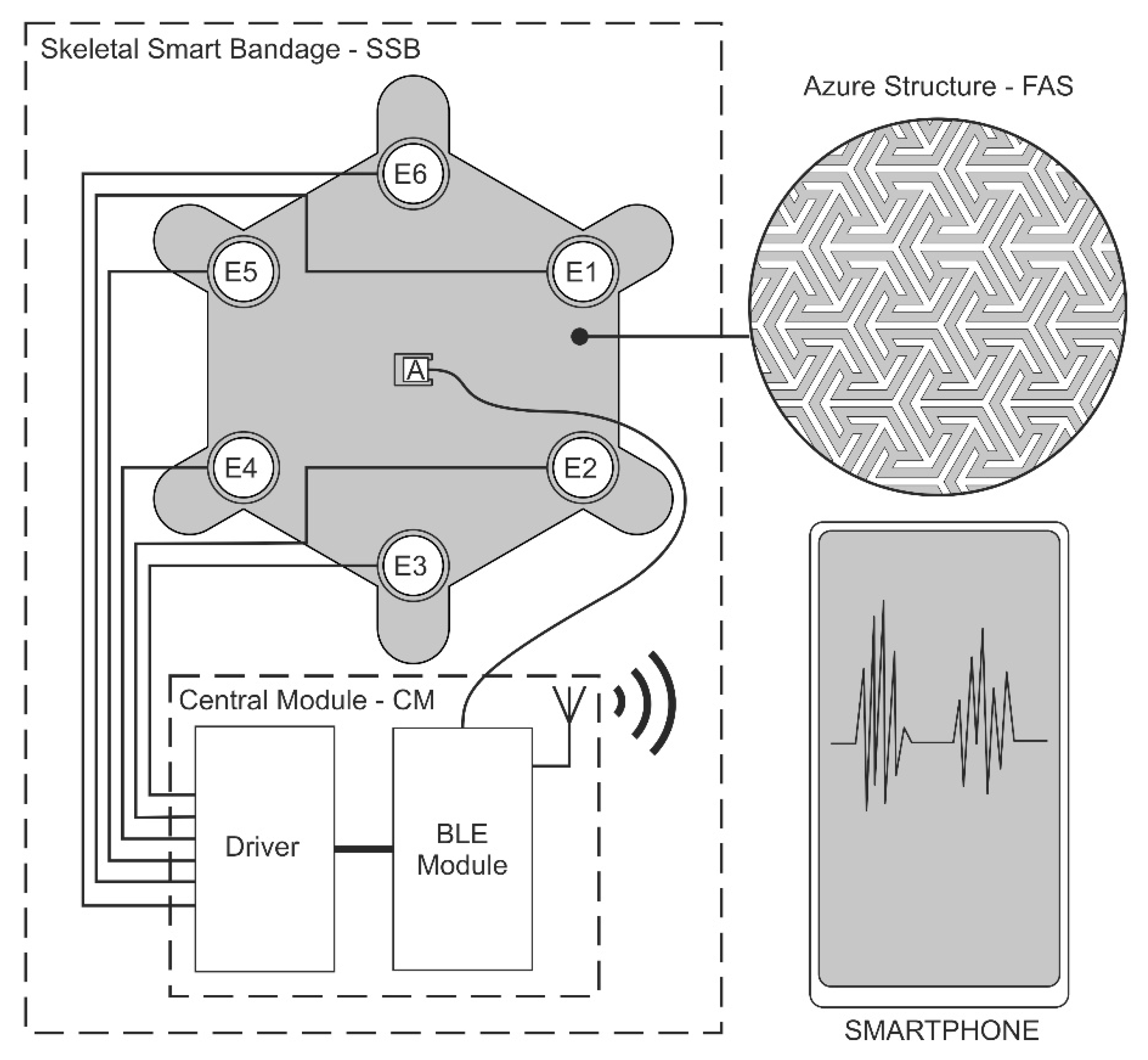
Figure 5.
View of the accelerometer placed in the slot in the central part of azure structure.
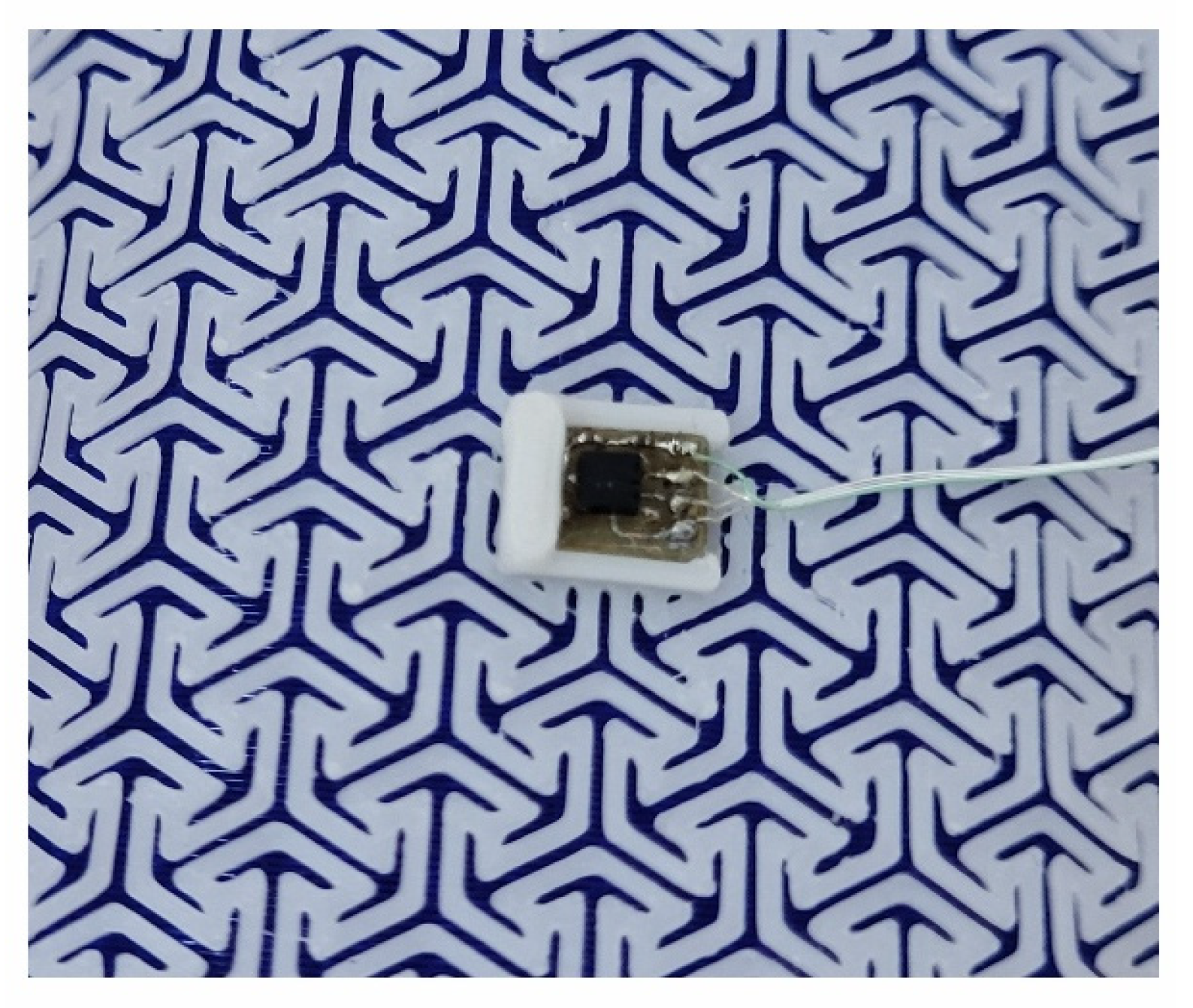
Figure 6.
Screenshots from the smart bandage mobile application.
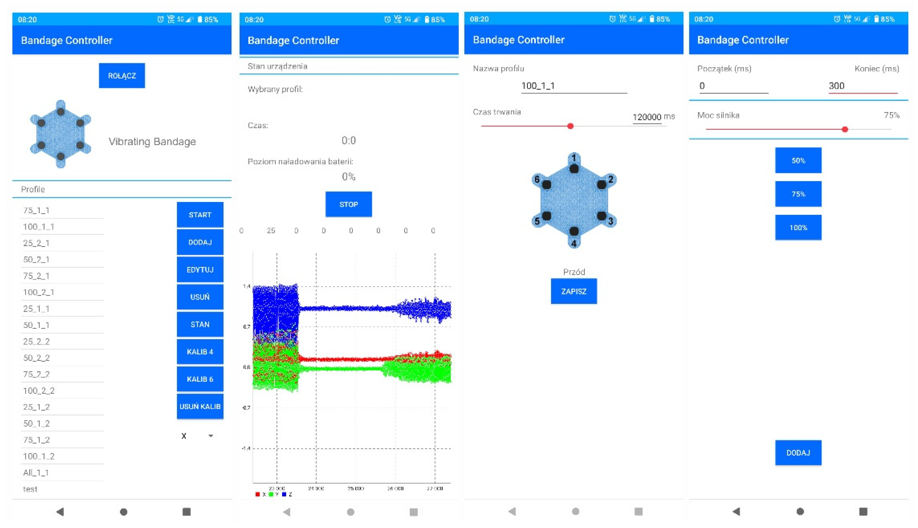
Figure 7.
Amplitude of oscillation when placing the smart bandage on the flat surface and supplying actuators with reduced voltage of 1.65V, before and after calibration, respectively, for: (a) resultant acceleration vector and its individual components: (b) along the x-axis, (c) along the y-axis and (d) along the z-axis.
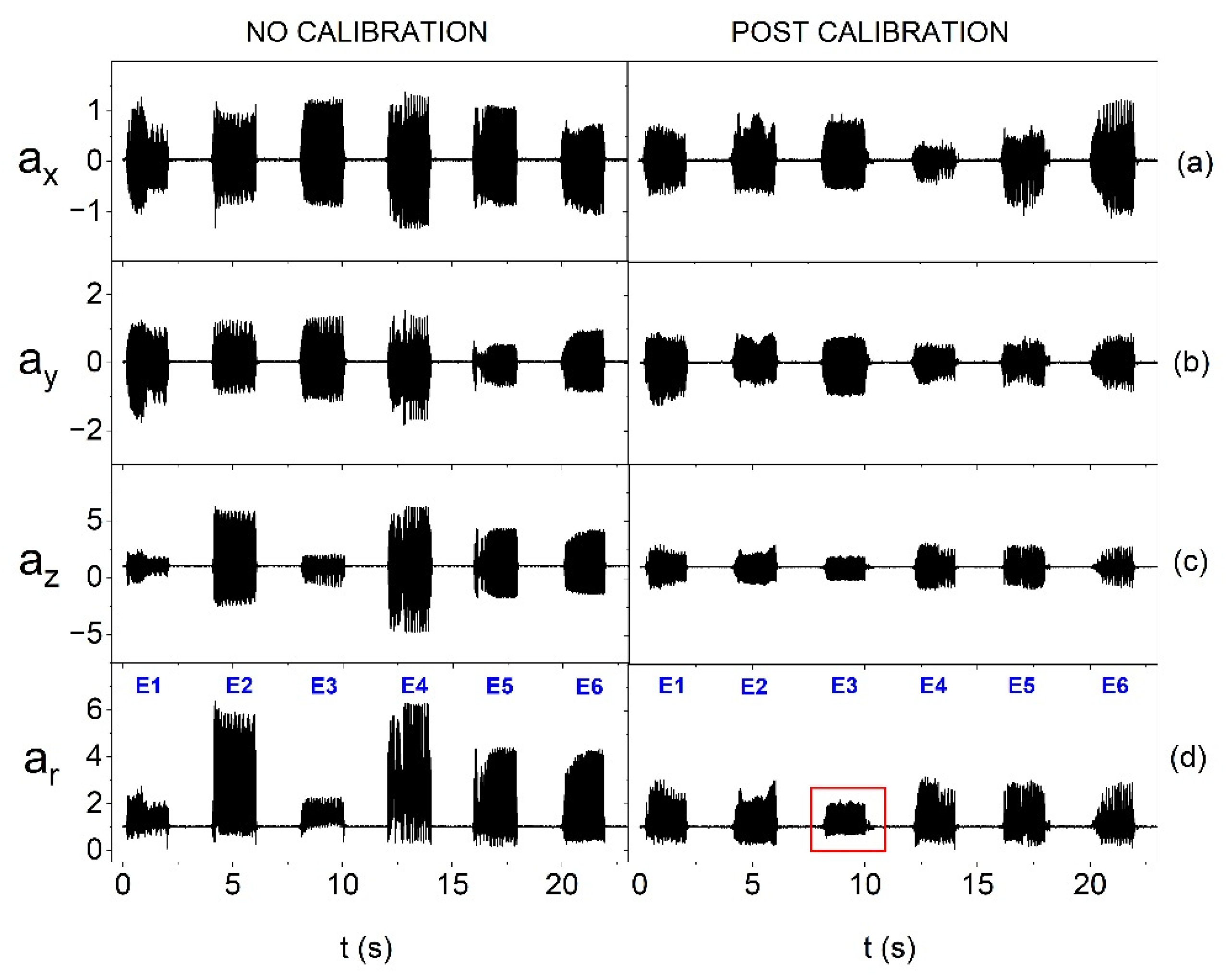
Figure 8.
Current consumption by individual oscillators at nominal supply voltage (3.17 V) and at voltage reduced to 1.65 V.
Figure 8.
Current consumption by individual oscillators at nominal supply voltage (3.17 V) and at voltage reduced to 1.65 V.
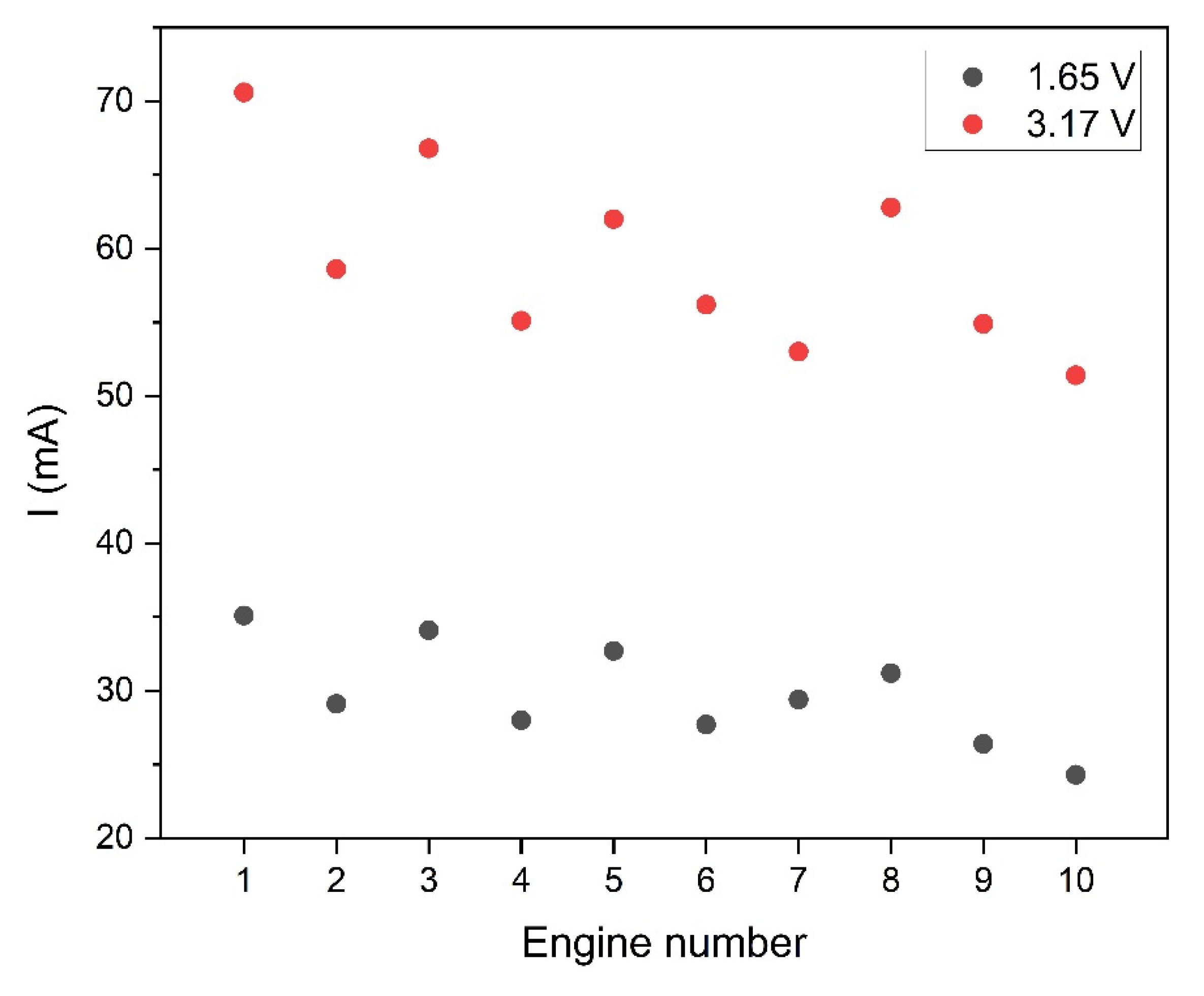
Figure 9.
Forearm phantom for testing the smart bandage on the convex surface (on the printed model of the upper limb fragment).
Figure 9.
Forearm phantom for testing the smart bandage on the convex surface (on the printed model of the upper limb fragment).
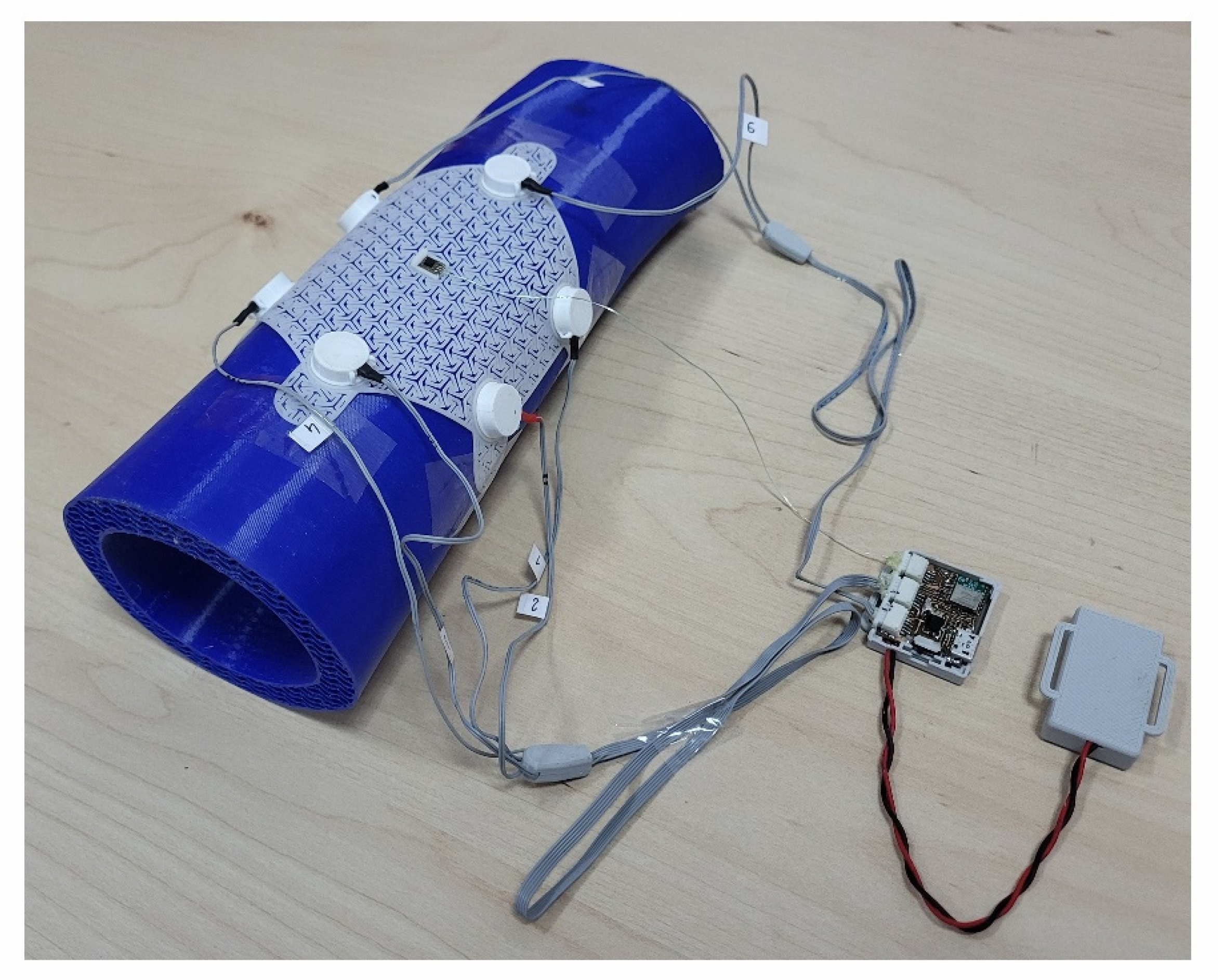
Figure 10.
Amplitude of oscillation for the resultant acceleration vector without calibration and after calibration for individual actuators (on the flat surface and with 1.65 V supply) depending on the material from which the azure structure was made: (a) Nylon, (b) PP and (c) TPU.
Figure 10.
Amplitude of oscillation for the resultant acceleration vector without calibration and after calibration for individual actuators (on the flat surface and with 1.65 V supply) depending on the material from which the azure structure was made: (a) Nylon, (b) PP and (c) TPU.
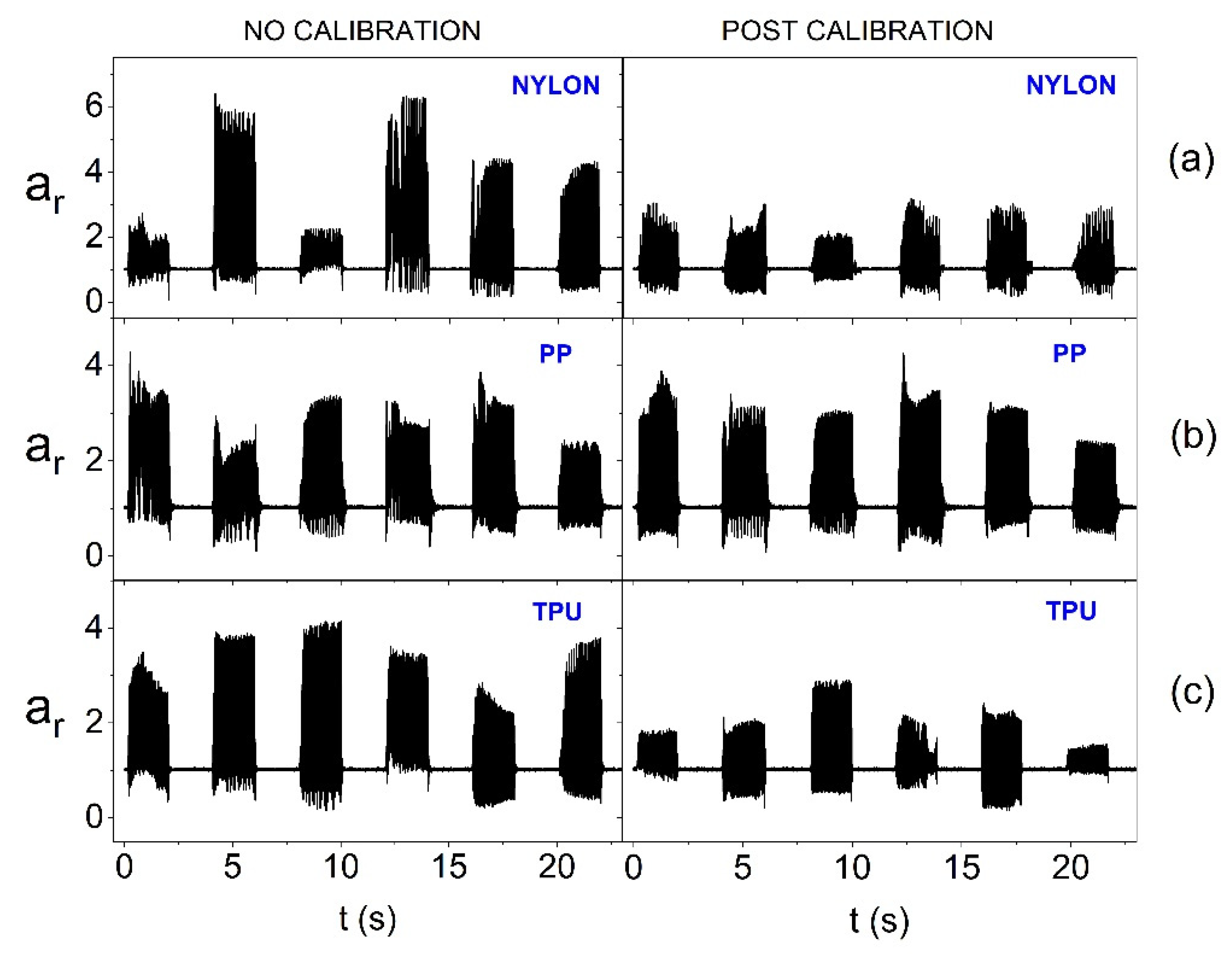
Figure 11.
Amplitude of oscillation for the resultant acceleration vector without calibration and after calibration for individual actuators (on the forearm phantom and with 1.65 V supply) depending on the material from which the azure structure was made: (a) Nylon, (b) PP and (c) TPU.
Figure 11.
Amplitude of oscillation for the resultant acceleration vector without calibration and after calibration for individual actuators (on the forearm phantom and with 1.65 V supply) depending on the material from which the azure structure was made: (a) Nylon, (b) PP and (c) TPU.
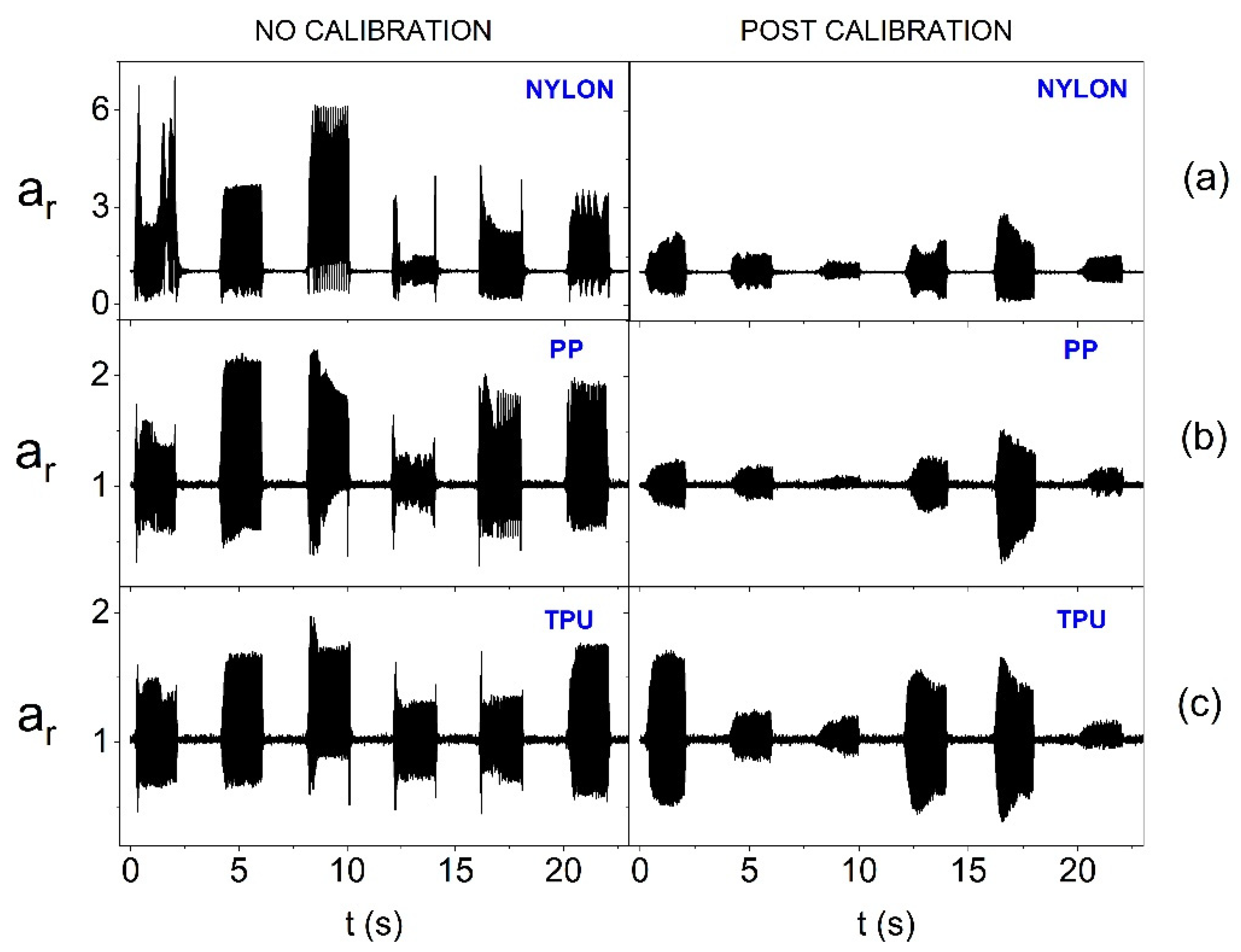
Figure 12.
Amplitude of oscillation for the resultant acceleration vector without calibration and after calibration for individual actuators (on the forearm phantom and with 3.17 V supply) depending on the material from which the azure structure was made: (a) Nylon, (b) PP and (c) TPU.
Figure 12.
Amplitude of oscillation for the resultant acceleration vector without calibration and after calibration for individual actuators (on the forearm phantom and with 3.17 V supply) depending on the material from which the azure structure was made: (a) Nylon, (b) PP and (c) TPU.
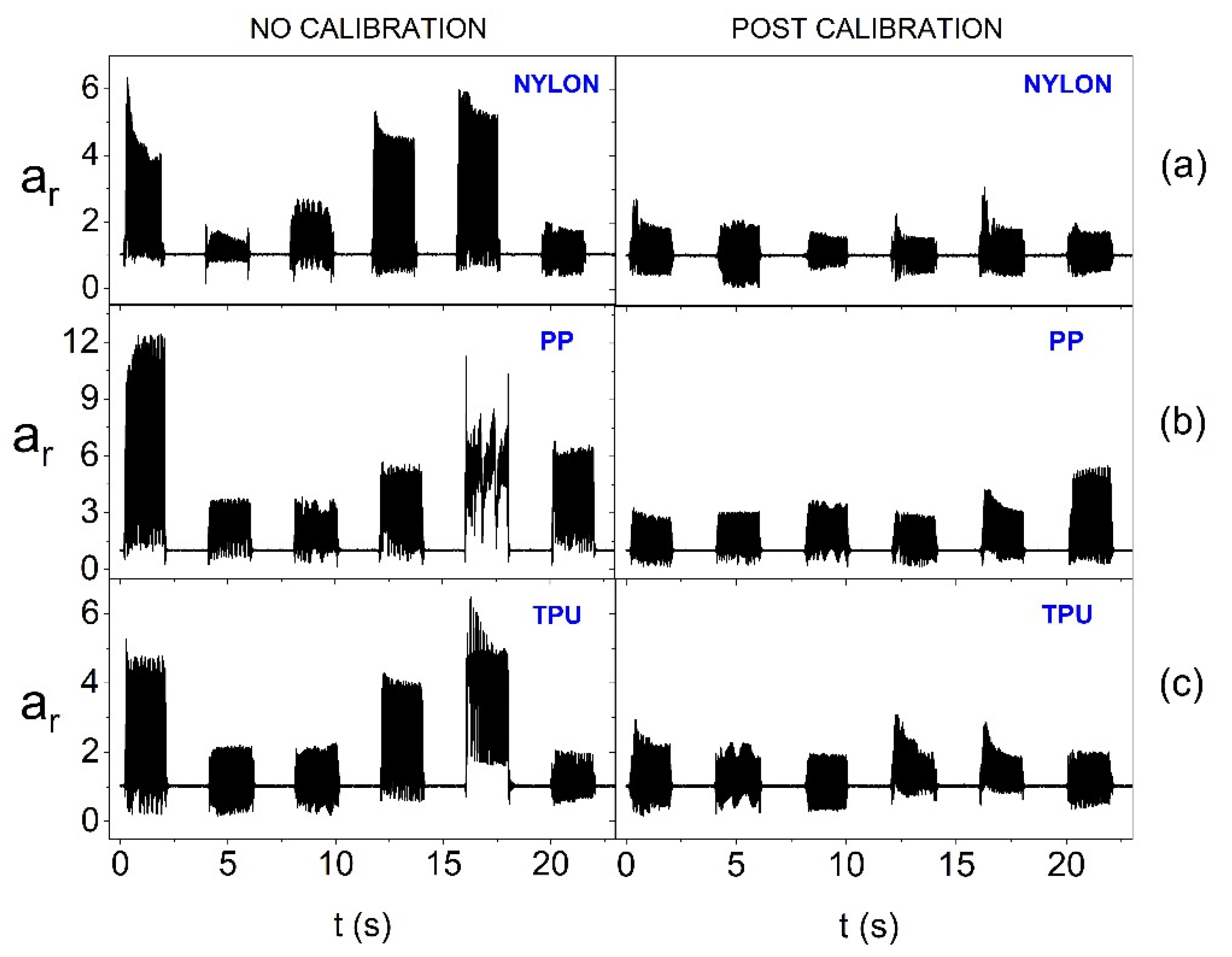
Figure 13.
FFT analysis results for two actuators (placed on the flat surface and with 1.65 V supply) depending on the material from which the smart bandage azure structure was made: (a) Nylon, (b) PP and (c) TPU.
Figure 13.
FFT analysis results for two actuators (placed on the flat surface and with 1.65 V supply) depending on the material from which the smart bandage azure structure was made: (a) Nylon, (b) PP and (c) TPU.
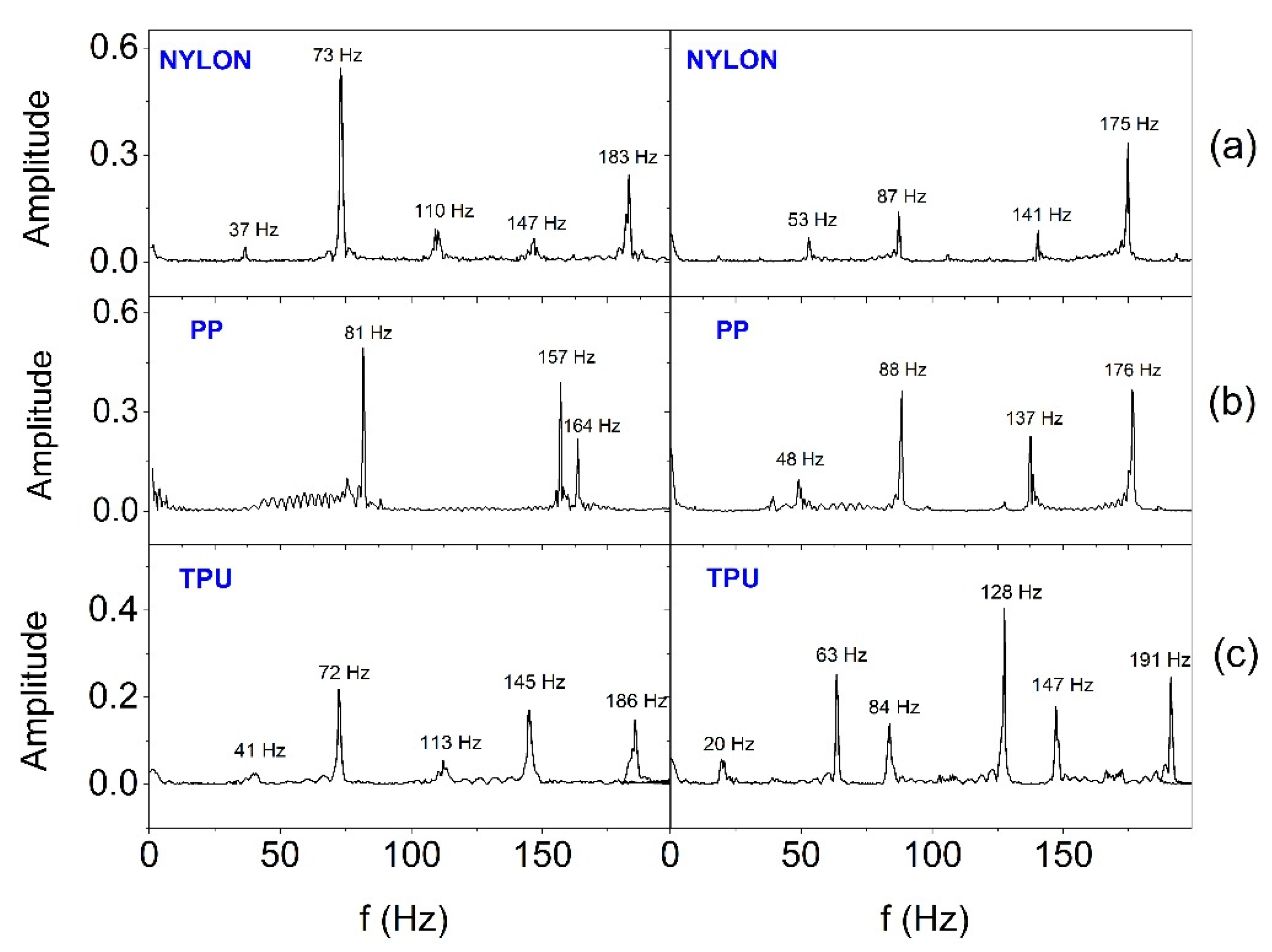
Figure 14.
FFT analysis results for two actuators (placed on the forearm phantom and with 3.17 V nominal supply) depending on the material from which the smart bandage azure structure was made: (a) Nylon, (b) PP and (c) TPU.
Figure 14.
FFT analysis results for two actuators (placed on the forearm phantom and with 3.17 V nominal supply) depending on the material from which the smart bandage azure structure was made: (a) Nylon, (b) PP and (c) TPU.
Disclaimer/Publisher’s Note: The statements, opinions and data contained in all publications are solely those of the individual author(s) and contributor(s) and not of MDPI and/or the editor(s). MDPI and/or the editor(s) disclaim responsibility for any injury to people or property resulting from any ideas, methods, instructions or products referred to in the content. |
© 2025 by the authors. Licensee MDPI, Basel, Switzerland. This article is an open access article distributed under the terms and conditions of the Creative Commons Attribution (CC BY) license (http://creativecommons.org/licenses/by/4.0/).
Copyright: This open access article is published under a Creative Commons CC BY 4.0 license, which permit the free download, distribution, and reuse, provided that the author and preprint are cited in any reuse.


