Submitted:
24 June 2025
Posted:
25 June 2025
You are already at the latest version
Abstract
For the development of a compact and low power system using IoT, biomedical and wearable applications, antenna based technologies for energy harvesting and wireless power transmission (WPT) have grown very significant. This review revisits improvements in antenna technologies achieved through fabrication and substrate materials and considering low cost FR4 as well as specialised flexible and textile integration substrates. The role of advanced manufacturing methods, such as PCB based designs, inkjet printing, and additive techniques, is discussed so as to enable compact, efficient, and conformal antenna structures. Both the common as well as the emerging approaches used in the energy harvesting and WPT are explored in this paper, that is, the broadband and multiband designs, which are crucial for the optimization of performance across different environments. This review attempts to give a present status of the studies, on implementing energy efficiency, substrate performance, and integration and the new tendencies on flexible antenna systems and the hybrid fabrication. Further research could concentrate on developing materials for the next generation, customized for specific applications antenna capability.
Keywords:
energy harvesting antennas
; wireless power transmission
; FR4 substrate
; flexible antennas
; advanced fabrication techniques
; multi-band antenna design
; PCB planar techniques
1. Introduction
With today’ advanced technological space, it is necessary to provide efficient, wireless, autonomous power solutions even more than needed. The reign of wired power supplies and replaceable batteries will not do well due to the proliferation of the Internet of Things (IoT), wearable electronics, and biomedical implants, as well as smart sensing systems. Energy harvesting antennas and wireless power transmission (WPT) systems are the transformational technologies in this context. Apart from the ability to minimise the constraints of wired connections, these systems are likely to have long-term operation of low-power electronic devices without routine maintenance or battery replacement.
Specifically, energy harvesting antennas are important in those types of applications, in which it is not possible or convenient to replace batteries manually, as in remote environmental sensors, implantable medical devices, and industrial monitoring systems. Then these antennas can convert ambient electromagnetic energy into usable electrical power, so they can operate autonomously. Similarly, wireless power transmission technologies are becoming popular in diverse applications such as smartphone charging, electric vehicles, biomedical devices, and smart textiles. It also provides flexibility to design, reduction of clutter, and improvement in user experience by delivering the power wirelessly.
Due to the limitation of direct physical connection or passive battery as a power delivery system, their system longevity and mobility are typically limited. Also, traditional antennas were developed mainly for communication purposes and had a small energy harvesting capacity [1]. New technological developments have brought into being multifunctional antennas that possess communication and power-harvesting features. The innovations are the result of the integration of advanced materials and design to improve performance and adaptability.
FR4, flexible polymers, and textile-based materials served as some of the emerging solutions to use specialized substrates in order to design antennas. Lightweight, conformal, and low-cost manufacturing can be achieved on these substrates because they are suitable for manufacturing wearable and portable electronics [2]. In addition, the performance of antennas has been significantly improved, and the manufacturing complexity is low by advanced fabrication techniques such as inkjet printing, screen printing, additive manufacturing, and laser machining [3]. There are a number of PCB-based and planar antennas, as well as textile-integrated and flexible antenna formulations, which have enabled WPT to be incorporated into varied environments and form factors [4]. These advancements are also capable of providing broadband and multi-band operation, which is increasingly important owing to the high demand for efficient and versatile power transfer.
Energy harvesting antennas are able to catch ambient radio frequency (RF) signals through rectification circuits in order to produce electrical energy from the ambient RF signal. Finally, wireless power transmission systems operate in either the near-field (inductive or capacitive coupling) or the far-field (radiative transfer) with an energy source and a receiver without direct contact. These technologies, compared with traditional methods, provide multiple advantages such as reduced maintenance, better reliability, allowance for better mobility, and environmental greenness. Nevertheless, energy conversion efficiency is low, alignment sensitivity and substrate losses are big problems, especially with the most commonly used material, FR4, to be taken for large-scale adoption.
The state and the potential of future energy harvesting and wireless power transmission antennas are explored by this review. This includes in depth discussion on energy harvesting antennas constructed on FR4 as well as other specialized substrates, and flexible designs for textile integrated systems. The review also introduces state of the art of wireless power transmission, including multi band and planar PCB, PCB and application specific implementation. The results lead to a critical analysis of existing literatures, trends in the research domain, and open challenges to present future directions and research opportunities of interest in this field. Figure 1.
2. Energy Harvesting
2.1. Antennas Using FR4 Substrate
In a research, the design of split ring resonator shaped monopole antenna, working as an antenna at various circular polarization frequencies in a low cost FR4 substrate as well as a multiband rectifier circuit coupled to this antenna is proposed using HFSS ver. 15. The circular polarization of the antenna with an antenna size 15 × 35 mm², thus allows usage of the antenna at any orientation for RF energy harvesting. Consequently, the matching bandwidth falls in the range of 2 GHz to 10 GHz with notches of 2.5 GHz to 3.5 GHz, which would effectively cover most of the wireless communication frequencies locally at −10 dB. Applying such mechanisms to a single-stage voltage doubler rectifier (VDR) connected to the RF input, this research converts the RF input into a DC signal, over the rapid, broadband of 2GHz to 10GHz, with improved efficiency, and in a compact package of 9.2 x 20 mm2. Due to its low power application, such as an IoT sensor, the ADS has optimized its matching circuit for the maximum DC output voltage of 0.94 V and 60.4% power conversion efficiency at −5 dBm input signal. A split ring-based metamaterial technique of introducing a tilted split ring absorber having compact size resonating at LTE2350, WiFi2450, and LTE2600 bands gives an achieved return loss of −15dB, −28dB, and −27dB, respectively. The absorption characteristics are improved [5]. Then it is further developed as a compact microstrip circular patch (CMCP) on FR4 substrate with a wide impedance bandwidth of 2.94 GHz (2.06–5.0 GHz) and more than 86% (95.4% measured at 2.45 GHz) of radiation efficiency and gain of 2.38 dBi at 2.45 GHz for use as an ambient RF energy harvesting technology for use in ISM (2.4 GHz), IMT (2.45 GHz), WiMAX (2.5 GHz) and satellite communication (2.5 GHz) applications [6]. Ultimately, a circular slot antenna that covers a wide band for RF signal harvesting in GSM1800, UMTS 2100, Wi-Fi 2450, and LTE 2600 is designed. Moreover, a circular ring radiating component (CRC) with slot and defected ground structure (DGS) is also provided to increase gain, and an impedance bandwidth of 1.510–1.590 GHz and a gain of up to 4.34 dBi is achieved [7]. In terms of manufacturing techniques, this design represents a smart solution in terms of the use of materials and resources at a low cost while being able to achieve an optimum performance of antenna performance and efficiency over various applications. Figure 2
2.2. Specialized Substrates
Wide dual bands were obtained when multiple radiating branches were combined with etching a C-shaped slot with constant compact dimensions of 7.9×7.7×1.27 mm³. However, in this case, the problem refers to the fact that the simulated bandwidths of the antenna’s impedance are between 0.67–1.05 GHz (approx. 44.2%), 2.11–2.96 GHz (33.5%), with peak gains dBi of approx. −28.9 dBi and −29.5 dBi, respectively [8]. To solve this, a circularly polarized (CP) high-gain hexagonal antenna array at 5.8 GHz was developed. However, both the X-shaped aperture coupling feed structure and frequency selective surface (FSS) are employed to maximize 12.7dBi per element and coverage of 360 degrees azimuth plane without any circuitry [9]. However, the structure of the design may be restricted to a defined, given operational frequency range. A top layer of lossy nickel (Ni), a dielectric SU8 layer and a bottom layer of lossy gold (Au) were designed for a UWB antenna to have a strong impedance match with an average absorption of 84.5% from 25 to 800 THz to serve the purpose of energy harvesting, THz, and broadband signal transmission [10]. Based on a CP ME dipole antenna with a complementary source technology, a CP complementary antenna array is proposed that can overcome possible bandwidth constraints in the millimeter (mm) wave frequency. The RFEH application is attributable to the overlapping bandwidth up to 33.87–43.15 GHz between the AR and impedance bandwidths, which was accorded in this design, given that the AR and impedance bandwidths are 24.8% and 25.7% centred at 25.2 GHz and 23.8 GHz, respectively, with the mean gain of 8.7 ± 1.6 dBic over the band. Hence, the antenna is desirable for mm Wave RFEH applications where the energy harvesting efficiency is increased, and a low-profile antenna with good performance is achieved [11]. Antennas made with a novel layer-by-layer approach of precise material and complementary sources integration were fabricated to enhance the efficiency of the antenna and its performance over a wide frequency band. Figure 3.
2.3. Advanced Fabrication Techniques
In a research, an ultrawide band (UWB) metamaterial (MTM) antenna structure is used as the form of ultrasound band (UWB) Hilbert metamaterial antenna structure for RF energy harvesting on an organic substrate. In the low-profile design, a rectangular MTM array for a wearable system has been proposed. The antenna is mounted on a prepared INP substrate based on indium-nickel oxide and Palm fibre (INP) polymerized Palm fiber substrate, using the ground plane of square electromagnetic band gap (EBG) defects. It is tested using the fifteen INP substrate samples using a T resonator transmission line technique printed on an FR4 substrate. By means of this technique, relative permittivity (εr) and permeability (μr) can be obtained from two resonators with different characteristic impedances to obtain substrate property controllability for microwave device products manufacturing. The fabricated antenna is based on silver nanoparticle (SNP) printout. Also, with the gain peaks at 3.5, 4.2, 5.4 and 6 GHz, the UWB response is brought out from 3 to 10 GHz in the useful bands for IoT, 5G and WiMAX networks. The conversion efficiency of the RF harvesting has also been experimentally inferred to be independent of the bending of the structure [12]. The Chand-Bali nano antenna has good performance compared to a moderate-gain UWB Hilbert-shaped MTM nano antenna by virtue of two elliptically shaped metallic patches for coupling to both polarizations. It is built upon a gold ground plane with TiO2 insulator to increase efficiency to a metal-insulator-metal (MIM) structure. The ability to rectify for efficient energy harvesting is also improved by placing a titanium patch. A ring slot covered frequency band from 2.1–3.2 GHz and 5–7.5 GHz, which is verified by HFSS ver. 15 simulation, a circular patch monopole was first designed. Consequently, it offers improved impedance matching and efficient RF energy harvesting from ambient sources of energy [13]. To solve the limitation of the ambient source, a hybrid solar and wireless energy harvesting system integrating rectifiers, a solar panel, and a tree-shaped antenna is made by enhancing a Chand-Bali antenna. Four 3D printed antennas do not impact the solar input and improve the RF harvested energy. In the laboratory, researchers evaluate the maximum power of the rectenna at 52.6% at 8 dBm RF power, and the maximum power of the solar panel is 7.3 mW. At the same time, it has a maximum gain of 6.0 dBi over a frequency range of 2.39 to 2.52 GHz. For 8 dBm input, 68.7% conversion efficiency for the RF-to-DC in the rectifier is reported [14]. The circular polarized metamaterial stacked antenna with the simple design of a circular stacked patch, branch line coupler, and energy harvesting unit is used to handle the complexity of the hybrid system. It has a 2-layer structure and offers 2-3 dB gain improvement over antennas with a similar number as Circular Split Ring Resonators (CSRR). The antenna operates over the frequency range of 2.4 GHz to 2.9 GHz with 87% efficiency, 20% bandwidth, gain of 7.9dBi. This includes autonomous operation to harvest energy into RF to DC power with rectifying diode inclusion, rechargeable battery, and ideal selection for IoT and medical applications [15].Figure 4.
2.4. Common Substrates and Techniques
A study proposes a meander line antenna as a structure to capture the ambient RF signals, which is in particular intended for deployments in RFID tags. This design has the advantage of being lightweight, compact, and very conformal, with good efficiency and small BW. It also improves performance by comparison with RF ICs [16]. The antenna used is a meander line antenna, and although it has to be with an EM4325 RF IC, the source impedance of the antenna. The UHF RFID tag antenna was designed and optimized using a high-performance 3D electromagnetic (EM) analysis software, CST 2019. Design, research, and optimal design of various EM components and systems were done in this software. In order to tackle the complex impedance of the meander line antenna with the plug in RF chip and the requirement to get an accurately matched impedance in order to optimize the attenuation at 919 MHz (close to UHF RFID 915 MHz band), a new system to feed the Wireless Sensor Network (WSN) with RF Energy Harvesting (RF EH) was proposed. Secondly, at fixed average power values (between 400 and 1000 W), values of power delivery to multiple target video cards are fed to the system, which in effect points back to the very first challenge that this system has created, of an impedance matching network. To minimize the relay antenna distance performance over, the system is realized on a Teflon glass substrate with a relative permittivity of 2.1 and a thickness of 0.67 mm. However, the design of the compact multi-band meander line antenna with more frequency adaptability and better performance is made using CST software. The reported device ranges over the communication bands of GSM-1800, UMTS, LTE-2.3, LTE-2.6, and in the form of a compact and efficient solution to power up DC output voltage and increase system operational range [17]. To overcome size and efficiency problems, a compact triple band triangular patch antenna for RF energy harvesting in IoT devices is proposed with a structure of three superposed triangular patch resonators so as to have higher surface current density and higher radiation efficiency. At the same time, it is demonstrated that the electric and magnetic field concentrations of this antenna are excellent in comparison with the previously mentioned circular and rectangular patches, and thus it is believed to be a potential candidate for RF energy harvesting tasks. Moreover, the antenna is omnidirectional and multi-slot with an efficient performance and a broad frequency adaptability [18]. Finally, scientists have proposed a transient type thermal energy harvester (TEH) to enhance the strengths of TEH to overcome the above limitations of the static TEH by using diurnal cycle temperature fluctuations. This intelligent integration allows the antenna to serve as a heatsink, and the device is optimized with respect to both RF and thermal energy harvesting. The heatsink antenna is designed for the multi-source ambient energy harvester, and it has an improved radiation efficiency, enhanced radiation efficiency, and heat dissipation [19]. The other solution is the application of Teflon glass and smart heating integration with heatsinks, which is a strategic solution to solve impedance matching, energy efficiency, multi-band adaptability issues, and leads to very effective RF energy harvesting solutions in various applications. Figure 5.
2.5. Diverse Applications and Techniques
A novel hybrid antenna for simultaneous RF energy harvesting (RF EH) and dedicated wireless power transfer (WPT) was proposed. The integration of an omnidirectional antenna element (GSM1800, UMTS2100, ISM2400/5800, 5G3500, WLAN bands) and a 2.4GHz dual polarization high-gain directional patch array element was incorporated. At the null of the omnidirectional beams in the WPT band (ISM - 2400), directional beams are located, and a pair of spatially complementary beams is created. It facilitates omnidirectional beams to pick up ambient RF energy from low elevation space to run low power circuits, as well as directional beams to pick up RF energy from a dedicated source to energize high power circuits. However, this approach could face difficulty in achieving consistent performance for all bands. Moreover, the hybrid antenna presents a spatially complementary feature that allows low mutual couplings between ports to keep the operation of both WPT and RF EH independent. To overcome this challenge, the proposed circularly polarized (CP) broadband rectenna enables the sensing nodes of smart cities to harvest radio frequency (RF) energy efficiently in the 5.8 GHz Wi-Fi band (5.725–5.875 GHz) or Wi-Fi 6E band (5.925–7.125 GHz) [20]. Figure 6.
An antenna derived from a semi-cylindrical dielectric resonator energised from a microstrip feed is improved in bandwidth, gain, and CP characteristics. The major disadvantage of the applications that need broad angular coverage is that its performance cannot cover all frequency bands. In order to overcome this, a radial array rectenna with a dual purpose is presented to enable Radio Frequency (RF) energy harvesting based Internet of Things (IoT) nodes orientation sensing with angular misalignment tolerance [21]. An azimuthally radial placement of eight rectenna elements is used to enhance the stability of the rectenna to energy harvesting RF energy from the entire 360° angular region with which it is enclosed. The energy harvesting capability of the design would vary depending on the orientation of the energy. The proposed microstrip coupled antenna (MCA) at 5.8 GHz has an efficient, high-gain structure with the use of the Frequency Selective Surface (FSS) to add to the increased gain of the antenna from 8 dBi to 12.7 dBi [22]. Under this design, researchers obtained full 360-degree coverage for full illumination of the hexagonal element pattern and substantial element gain (12.7 dBi). It exhibits consistent performance without any other circuitry and, therefore, is highly suitable for wireless power transfer (WPT) and other applications that find angular alignment difficult [9]. These designs have a high innovation level in fabrication technique and are power efficient; therefore, they can be used as a potential for more advanced RF applications. Table 1
3. Wireless Power Transmission
3.1. PCB and Planar Techniques
For the WPT (Wireless Power Transfer) system, the antenna used consists of a two-dimensional continuous aperture antenna placed on the ceiling. The system further consists of a small omnidirectional radiating element inside the x−z plane. Consequently, the radiating elements are arranged in such a manner that the mutual coupling and obstruction between all and any radiating element are kept to a minimum while minimizing loss of energy from the transmitting end to the receiving end. A power-dividing rectenna system taking advantage of the strong Line of Sight (LoS) properties of the mmWave frequency band [25] was proposed which is integrated with circular patch antenna using coupled stacked substrate with 10 way radial power divider. This compact printed rectenna circuit also offers improved efficiency and impedance matching that is precisely achieved, while being capable of handling high power levels [26]. A rectangular patch antenna with dual-band resonance was proposed in order to increase versatility and efficiency [27].Figure 7.
The concrete parameters are specified according to their contributions and features suitable for wireless power transfer applications with working frequencies of 900 MHz and 1450 MHz, respectively, and with maximum Power Conversion Efficiencies (PCE) of 53% and 54% in various load and input power ranges, respectively. Series-fed antennas on Taconic RF-35 dielectric substrate are adopted to achieve such applications to improve compactness and eliminate radiation loss [27], which improves the gain by 1.88 dB at 0.9 GHz and 2.6 dB at 1.45 GHz and radiation efficiency by 82.3 % and 90.6 % respectively, making them a strong choice for wireless communication. These antennas are efficient in beam tilting and robust. These techniques are therefore appropriate for wireless power transmission, radar and communication systems [28], and it increases efficiency, flexibility, and functionality sweet spot for any application to formulate advanced wireless power transmission systems application.
3.2. Textile-Integrated and Flexible Antennas
In a work, a fully woven textile integrated 2.4 GHz rectangular patch was designed with truncated corners as a radiating element for wireless power transfer applications, and demonstrated that the resulting rectenna has enhanced the first few modes that come in pairs, driven by the even and odd fields, resulting in circular polarization. It was fed into the T-match structure with impedance control without additional networks. Single-diode rectifier topology is used for integration with the antenna, and it simplifies the integration process. The co-simulation is performed, and the impedance of the rectifier and antenna were matched to maximize the power transfer [29]. This provides high compatibility and comes with 45% efficiency. The directional button antenna with AMC cells attached to and fed by an all-fabric microstrip line is used to further improve the structure as a monopole radiator. To achieve the improvement in matching, lowering of the height, and elimination of back radiation for improved on-body wireless power transfer, it uses the TP1020 and FR4 substrates with 180° phase difference and 1.07 GHz bandwidth [30]. Additionally, a planar-spiral LIC-antenna was built with a wire width of 1.0 mm, 5,000 bending cycles mechanical durability, conductivity of (1.71×10⁶ S/m), and without performance degradation. With WPT, NFC, and WIPT support, WPT achieves high radiation efficiency (88%) and peak gain of 6.1 dBi, which makes it a good, cost–efficient way of providing an effective solution for wearable electronics and IoT [31]. At last, the antenna is a planar octagonal loop with 3 × 3 ring-shaped FSS at 2.40 GHz for body isolation. It has a 2.70 mm thickness and a flexible PDMS substrate that is silver epoxy and EGaIn printed or conductively written onto tattoo paper. The performance of loops and stubs is the same in terms of matching loops and stubs, excluding impedance, and the stabilized performance when deformed; the high radiation efficiency, up to 75.5 % lower SAR value, compatible with low power devices, leads to practical, highly arranged everyday wearable electronics [32]. To improve the conductivity, flexibility, and mechanical durability of the antennas, along with increasing the electrical efficiency, reducing cost, and achieving big reconfigurability for wearables, advanced fabrication techniques such as laser direct writing and novel substrate material were integrated. Figure 8.
3.3. Advanced Manufacturing and Innovative Designs
Radio Frequency Energy Harvesting (RFEH) and Wireless Power Transfer (WPT) power is provided by low-power devices. The key to the extent to which this depends on, antenna design. One of the innovative designs is a cube 3D antenna based on the quasi-Yagi antenna (QYA) design and optimized for operation at 915 MHz. As detailed in [33], the wireless power transfer (PTE) efficiency of implantable medical devices can be increased by using a receiving rectenna with multidirectional reception in order to gain an efficient rate of capturing different amounts of dedicated and ambient energy. The mechanical antenna of this rectenna is a magneto-electric (ME) heterostructure and an RF inductive coil. Consequently, this design enhances the PTE from 2.8159%, which is greater than attained by a single ME antenna or an inductive coil alone. In addition, a novel 24 GHz beam-steerable multimode WPT system is also designed to improve the efficiency and is especially useful for wireless biomedical devices [34]. Further, this system introduces a new FoM for cost efficiency and spatial coverage. It includes an 8 × 8 phased aray transmitter and 5 × 5 high gain angle deflection planar rectennas which reduce the need for precise placement [35]. In addition, a polarization-insensitive rectenna based on an MS was developed, overcoming the polarization mismatch issues with WPT systems at 5.8 GHz. A meandered groove is included in the MS element to suppress second harmonic generation, and a maximum conversion efficiency of 66% is achieved with resistive load of 500 Ω. The antenna design allows for any polarization scenario, and with this new rectenna design, it provides a promising opportunity for efficient WPT [36].The fabrication techniques used in these antenna designs significantly enhance their efficiency, directionality, and for various applications in wireless power transfer.
3.4. Wireless Power Transfer for Specialized Applications
This WPT system is realized on the ceiling with a special type of antenna. It is made up of perhaps many small omnidirectional antennas in a two-dimensional grid. They carefully place these antennas so they don’t interfere with each other and maximize the energy transmission. They are good with the Line of Sight (LoS) characteristics of the mmWave frequency band. The system setup allows for the transmission of power wirelessly to multiple receivers, reduces the chance that signals get blocked, like in offices or homes, while the system is compact for biomedical applications with an implantable Rx and Tx antenna [25]. They are tuned to work at 1.71 GHz. The Rx antenna is formed by a meander-line slotted radiator and a ‘C’ shaped slot in the ground plane, both of them in a biocompatible structure. A small, impedance-matched and environment-constant antenna design for the ASW-Tx is evaluated using two Taconic TLY-5 substrates for problems from misalignment and environment change [37]. There is an anti-symmetric wing plane in the excitation plane located beneath. These features render these antennas adaptable to angular misalignment so as to increase current intensity and provide stable power transfer efficiency in the actual real-life biomedical implant situation [38], while the antennas for the applications with Ultra wideband (UWB) performance are 4×4 Phased Array (PA) antennas. On the link, 16 single patch antennas with optimized beams for 7.5–8.5 GHz were observed. However, the setup has several advantages, such as high gain, wide bandwidth, and effective beam steering, which are appropriate for far field impulse radio UWB wireless power transfer applications [39].
3.5. Broadband and Multi-Band Antenna Designs
A wideband DCP radiation, low-profile, and low-cost antenna is proposed. Competitive performance along with the use of a shared subarray aperture across both circularly polarized (CP) states is also explored as part of the design. Five patch elements form basic structure; first state is CP1 that is realized using a central patch and second state was CP2, which can be demonstrated with four surrounding patches. Sequential rotation with polarization purity obtained in a low axial ratio and cross polarization with large-scale arrays [40]. A study then also presents a tightly coupled dipole array (TCDA) antenna for low cost and lightweight that includes a simple H-plane scanning booster (HSB) layer for consistent E and H plane scanning and uses a novel 1:4 differential feed network. However, this design nevertheless overcomes the limitation [41] for the scanning performance, which offers ±50° wide range scanning with low cross-polarisation levels below -30.5 dB. Additionally, the wireless power transfer for a microstrip patch antenna array utilizes high directivity and highly efficient beam steering, with a TX antenna gain of 9.8 dBi and efficiency of 68.07%. In RX, a quarter-wave transformer is used to increase the efficiency of energy delivery and therefore the optimal reception from 9° to 54° [42]. Finally, the techniques of cutting angle at the patch corners of the proposed wide band monopole antenna design and modifying the feed line have been applied to enhance the impedance bandwidth of the proposed wide band monopole antenna design. In addition, its bandwidth is 506 MHz, operating from 0.554 to 1.06 GHz, and consequently, it has proved suitable for UHF-RFID systems with an enhanced bandwidth of the impedance, improvement of matching and coupling [43]. Generating the designs involves a strategic use of shared apertures, sequential rotation, and optimized feed networks that enhance polarisation purity, bandwidth, and/or beam steering capabilities. Table 2
4. Conclusion
This review provides an overview of recent progress in antenna-based energy harvesting and wireless power transmission (WPT) by providing an importance for such compact, wireless enabling, and low-maintenance systems in IoT, biomedical devices, and wearables. These technologies are more flexible and sustainable than traditional wired or battery-powered ones. FR4 substrates are used for cost-effective implementation, and specialized and flexible substrates are utilized for supporting diverse or specific application designs. In addition, the planar, textile-integrated, and conformal antennas that have been made possible through advanced fabrication techniques, which include PCB-based, ink-jet printing, and additive manufacturing, improve functionality and integration. The review also summarized key elements such as broadband and multi-band operation, as well as the material property to antenna performance interaction responsible for efficient power harvesting and transfer. Although significant progress has been made, the problem of energy conversion efficiency is still affected by losses, implying minimal loss and scalability, especially for flexible and wearable formats. Now, the directions of current research include improving the materials, improving the design process, and merging new hybrid solutions to solve these limitations. Similar to advanced substrates, support for FR4 materials remains, but new approaches for design become possible with the study of new substrates. The future work should look into combining traditional with emerging materials, improving the fabrication precision, and tailoring the antenna structure for real-world conditions. With a small portion of the field developed, performance can be improved, applications can be further extended, and demand for smart, wireless energy systems can be met.
Author Contributions
DUR: Written original draft; conducted a survey of the literature; prepared the tables; collected the references; methodology; edited and proofread the final manuscript. All authors have approved the final version of the manuscript.
Funding
No funding was provided for the development of this manuscript.
Availability of Data and Material
All data relevant to this review are included in the text, references, tables, and figures.
Ethics Approval and Consent to Participate
Not applicable.
Consent for Publication
Not applicable.
Acknowledgments
The authors would like to express sincere gratitude to the Shreenivas Deshpande Library at the Indian Institute of Technology (BHU) Varanasi for providing invaluable resources and support.
Conflicts of Interest
The authors declare that they have no competing interests.
References
- Ullah, M.A., et al., A review on antenna technologies for ambient RF energy harvesting and wireless power transfer: Designs, challenges and applications. IEEE Access, 2022. 10: p. 17231-17267.
- Carvalho, S.S.; Reis, J.R.V.; Caldeirinha, R.F.S. A State-of-the-Art Review on 4D Printed Antennas and Other Adaptable Designs. IEEE Access 2024, 12, 62861–62881. [CrossRef]
- Chietera, F.P. Additively Manufactured Antennas and Electromagnetic Devices. Hardware 2024, 2, 85–105. [CrossRef]
- Song, C.; Ding, Y.; Eid, A.; Hester, J.G.D.; He, X.; Bahr, R.; Georgiadis, A.; Goussetis, G.; Tentzeris, M.M. Advances in Wirelessly Powered Backscatter Communications: From Antenna/RF Circuitry Design to Printed Flexible Electronics. Proc. IEEE 2021, 110, 171–192. [CrossRef]
- Persis, G.E.; Paul, J.J.; Mary, T.B.; Joy, R.C. A compact tilted split ring multiband metamaterial absorber for energy harvesting applications. Mater. Today: Proc. 2022, 56, 368–372. [CrossRef]
- Prashad, L.; Mohanta, H.C.; Mohamed, H.G. A Compact Circular Rectenna for RF-Energy Harvesting at ISM Band. Micromachines 2023, 14, 825. [CrossRef]
- Muhammad, S.; Smida, A.; Waly, M.I.; Mallat, N.K.; Iqbal, A.; Khan, S.R.; Alibakhshikenari, M.; Kumar, A. Design of Wideband Circular-Slot Antenna for Harvesting RF Energy. Int. J. Antennas Propag. 2022, 2022, 1–9. [CrossRef]
- Fan, Y.; Liu, X.; Xu, C. A Broad Dual-Band Implantable Antenna for RF Energy Harvesting and Data Transmitting. Micromachines 2022, 13, 563. [CrossRef]
- Derbal, M.C.; Nedil, M. High-Gain Circularly Polarized Antenna Array for Full Incident Angle Coverage in RF Energy Harvesting. IEEE Access 2023, 11, 28199–28207. [CrossRef]
- Wang, W.-C.; Garu, P. Design of an ultra-wideband omnidirectional and polarization insensitive flower petal antenna for potential ambient electromagnetic energy harvesting applications. Sci. Rep. 2022, 12, 1–16. [CrossRef]
- Sang, J.; Qian, L.; Li, M.; Wang, J.; Zhu, Z. A Wideband and High-Gain Circularly Polarized Antenna Array for Radio-Frequency Energy Harvesting Applications. IEEE Trans. Antennas Propag. 2023, 71, 4874–4887. [CrossRef]
- Alaukally, M.N.N.; Elwi, T.A.; Atilla, D.C. Miniaturized flexible metamaterial antenna of circularly polarized high gain-bandwidth product for radio frequency energy harvesting. Int. J. Commun. Syst. 2021, 35, e5024. [CrossRef]
- Elsharabasy, A.Y.; Bakr, M.H.; Deen, M.J. Optimized polarization-independent Chand-Bali nano-antenna for thermal IR energy harvesting. Sci. Rep. 2023, 13, 1–11. [CrossRef]
- Wang, T.; Huang, K.; Liu, W.; Hou, J.; Zhang, Z. A hybrid solar-RF energy harvesting system based on tree-shaped antenna array. Int. J. RF Microw. Comput. Eng. 2022, 32. [CrossRef]
- Sabban, A. Wearable Circular Polarized Antennas for Health Care, 5G, Energy Harvesting, and IoT Systems. Electronics 2022, 11, 427. [CrossRef]
- Veloo, S.G.; Tiang, J.J.; Muhammad, S.; Wong, S.K. A Hybrid Solar-RF Energy Harvesting System Based on an EM4325-Embedded RFID Tag. Electronics 2023, 12, 4045. [CrossRef]
- Benkalfate, C.; Ouslimani, A.; Kasbari, A.-E.; Feham, M. A New RF Energy Harvesting System Based on Two Architectures to Enhance the DC Output Voltage for WSN Feeding. Sensors 2022, 22, 3576. [CrossRef]
- Benkalfate, C.; Ouslimani, A.; Kasbari, A.-E.; Feham, M. A New Compact Triple-Band Triangular Patch Antenna for RF Energy Harvesting Applications in IoT Devices. Sensors 2022, 22, 8009. [CrossRef]
- Bakytbekov, A.; Nguyen, T.Q.; Zhang, G.; Strano, M.S.; Salama, K.N.; Shamim, A. Dual-Function Triple-Band Heatsink Antenna for Ambient RF and Thermal Energy Harvesting. IEEE Open J. Antennas Propag. 2022, 3, 263–273. [CrossRef]
- Liu, S.-B.; Zhang, F.-S.; Boyuan, M.; Gao, S.-P.; Guo, Y.-X. Multiband Dual-Polarized Hybrid Antenna With Complementary Beam for Simultaneous RF Energy Harvesting and WPT. IEEE Trans. Antennas Propag. 2022, 70, 8485–8495. [CrossRef]
- Surender, D.; Halimi, A.; Khan, T.; Talukdar, F.A.; Kishk, A.A.; Antar, Y.M.; Rengarajan, S.R. Semi-Annular-Ring slots loading for broadband circularly polarized DR-Rectenna for RF energy harvesting in smart city environment. AEU - Int. J. Electron. Commun. 2022, 147. [CrossRef]
- Kumar, M.; Kumar, S.; Sharma, A. Dual-Purpose Planar Radial-Array of Rectenna Sensors for Orientation Estimation and RF-Energy Harvesting at IoT Nodes. IEEE Microw. Wirel. Components Lett. 2022, 32, 245–248. [CrossRef]
- Morsy, M.A.; Saleh, K. Integrated Solar Mesh Dipole Antenna Based Energy Harvesting System. IEEE Access 2022, 10, 89083–89090. [CrossRef]
- Elshaekh, D.N.; Mohamed, H.A.; Shawkey, H.A.; Kayed, S.I. Printed circularly polarized spilt ring resonator monopole antenna for energy harvesting. Ain Shams Eng. J. 2023, 14. [CrossRef]
- Mayer, K.M.; Cottatellucci, L.; Schober, R. Optimal Transmit Antenna Deployment and Power Allocation for Wireless Power Supply in an Indoor Space. IEEE Open J. Commun. Soc. 2024, 5, 3624–3640. [CrossRef]
- Kim, D.H.; Oh, S.Y.; Park, H.S.; Hong, S.K. A Power Dividing Rectenna System for High-Power Wireless Power Transfer for 2.45-GHz Band. IEEE Access 2024, 12, 86631–86638. [CrossRef]
- Rosaline, I.; Shastry, P.; Venkatesan, R.; Tamilarasan, I. Design and optimization of a miniaturized dual band rectenna for wireless power transfer applications. Results Eng. 2024, 22. [CrossRef]
- Park, M.Y.; Kim, J.H.; Yi, S.-H.; Lim, W.; Yang, Y.; Hwang, K.C. Design of Series-Fed Circularly Polarized Beam-Tilted Antenna for Microwave Power Transmission in UAV Application. Appl. Sci. 2024, 14, 3490. [CrossRef]
- Fernández, M.; Vázquez, C.; Hoeye, S.V. 2.4 GHz Fully Woven Textile-Integrated Circularly Polarized Rectenna for Wireless Power Transfer Applications. IEEE Access 2024, 12, 89836–89844. [CrossRef]
- Xu, Y., et al., Wearable Directional Button Antenna for On-Body Wireless Power Transfer. Electronics, 2023. 12(8): p. 1758.
- Yang, B.; Xia, Y.; Zhi, X.; Liu, K.; Li, M.; Wang, X. Low-cost, wearable, multifunctional antennas based on laser-induced copper for wireless information and power transmission. Device 2024, 2. [CrossRef]
- Chang, X.L.; Chee, P.S.; Lim, E.H. Compact conformal tattoo-polymer antenna for on-body wireless power transfer. Sci. Rep. 2023, 13, 1–12. [CrossRef]
- Nando, Y.A.; Chung, W.-Y. Enhancing RF Energy Harvesting and Wireless Power Transfer with GAN-Optimized 3D Quasi-Yagi Antenna. 2024 IEEE Wireless Power Technology Conference and Expo (WPTCE). LOCATION OF CONFERENCE, JapanDATE OF CONFERENCE; pp. 454–458.
- Ma, Y.; Liu, C.; Huang, Y.; Ke, H.; Liu, X. Combined Magnetoelectric/Coil Receiving Antenna for Biomedical Wireless Power Transfer. IEEE J. Electromagn. Rf Microwaves Med. Biol. 2024, 9, 15–26. [CrossRef]
- Jiang, B.; Li, P.; Zheng, S.; Lin, Y.; Xu, H. A 24-GHz Beam-Steerable Multinode Wireless Power Transfer System With a Maximum DC Output of 5.7 dBm at 1-m Distance. IEEE Trans. Microw. Theory Tech. 2024, 72, 6774–6789. [CrossRef]
- Chang, M.; Li, Y.; Han, J.; Liu, H.; Li, L. A Compact Polarization-Insensitive Rectenna With Harmonic Suppression for Wireless Power Transfer. IEEE Antennas Wirel. Propag. Lett. 2023, 23, 119–123. [CrossRef]
- Khan, D.; Ahmad, A.; Choi, D.-Y. Design and Optimization of a Mid-Field Wireless Power Transfer System for Enhanced Energy Transfer Efficiency. Symmetry 2024, 16, 753. [CrossRef]
- Le-Huu, H.; Seo, C. Anti-Symmetric Wing Transmitter for Angular Misalignment Insensitive Wireless Power Transfer to Biomedical Implants. IEEE Access 2023, 11, 26375–26382. [CrossRef]
- Patwary, A.B. and I. Mahbub, 4× 4 UWB Phased Array Antenna with> 51∘ Far-Field Scanning Range for Wireless Power Transfer Application. IEEE Open Journal of Antennas and Propagation, 2024. 5(2): p. 354-367.
- Almalki, M.; Podilchak, S.K. Wideband Multiport Antenna Design by Subarray Aperture Sharing Offering Dual-Circularly Polarized Beamforming for Wireless Power Transfer. IEEE Antennas Wirel. Propag. Lett. 2024, 23, 3852–3856. [CrossRef]
- Wen, L.; Sanz-Izquierdo, B.; Hu, W.; Lin, C.; Wang, C. Lightweight, Low-Cost, Tightly Coupled Dipole Array Antenna for Wireless Power Transfer. IEEE Antennas Wirel. Propag. Lett. 2024, 23, 3797–3801. [CrossRef]
- Pirzada, B.S.; Shafique, K.; Jawed, S.A.; Muqim, I.; Amin, S.U.; Abubaker, F.; Khan, F.; Shahbaz, M.A.; Jabbar, M.J.; Abbas, M.F. A mid-range wireless power transfer system for portable electronic devices using beam forming. Analog. Integr. Circuits Signal Process. 2023, 115, 195–209. [CrossRef]
- Moloudian, G.; Buckley, J.L.; O’fLynn, B. A Novel Rectenna With Class-F Harmonic Structure for Wireless Power Transfer. IEEE Trans. Circuits Syst. II: Express Briefs 2023, 71, 617–621. [CrossRef]
- Kumar, S.; Kumar, M.; Sharma, A.; Zuazola, I.J.G. Energizing an IoT Sensor Using Regenerative Opposite Fringing Fields From an Embedded Communicating Patch Antenna. IEEE Access 2024, 12, 47951–47960. [CrossRef]
- Yu, Y.; Liang, C.; Wan, Q.-Q.; Jin, D.; Liu, X.; Zhang, Z.; Sun, Z.-Y.; Zhang, G.-J. Integrated FET sensing microsystem for specific detection of pancreatic cancer exosomal miRNA10b. Anal. Chim. Acta 2023, 1284, 341995. [CrossRef]
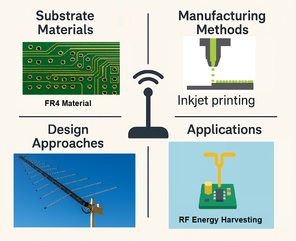
Figure 1.
Advancements in Antenna Technologies for Flexible Energy Harvesting and Wireless Power Transmission Systems.
Figure 1.
Advancements in Antenna Technologies for Flexible Energy Harvesting and Wireless Power Transmission Systems.
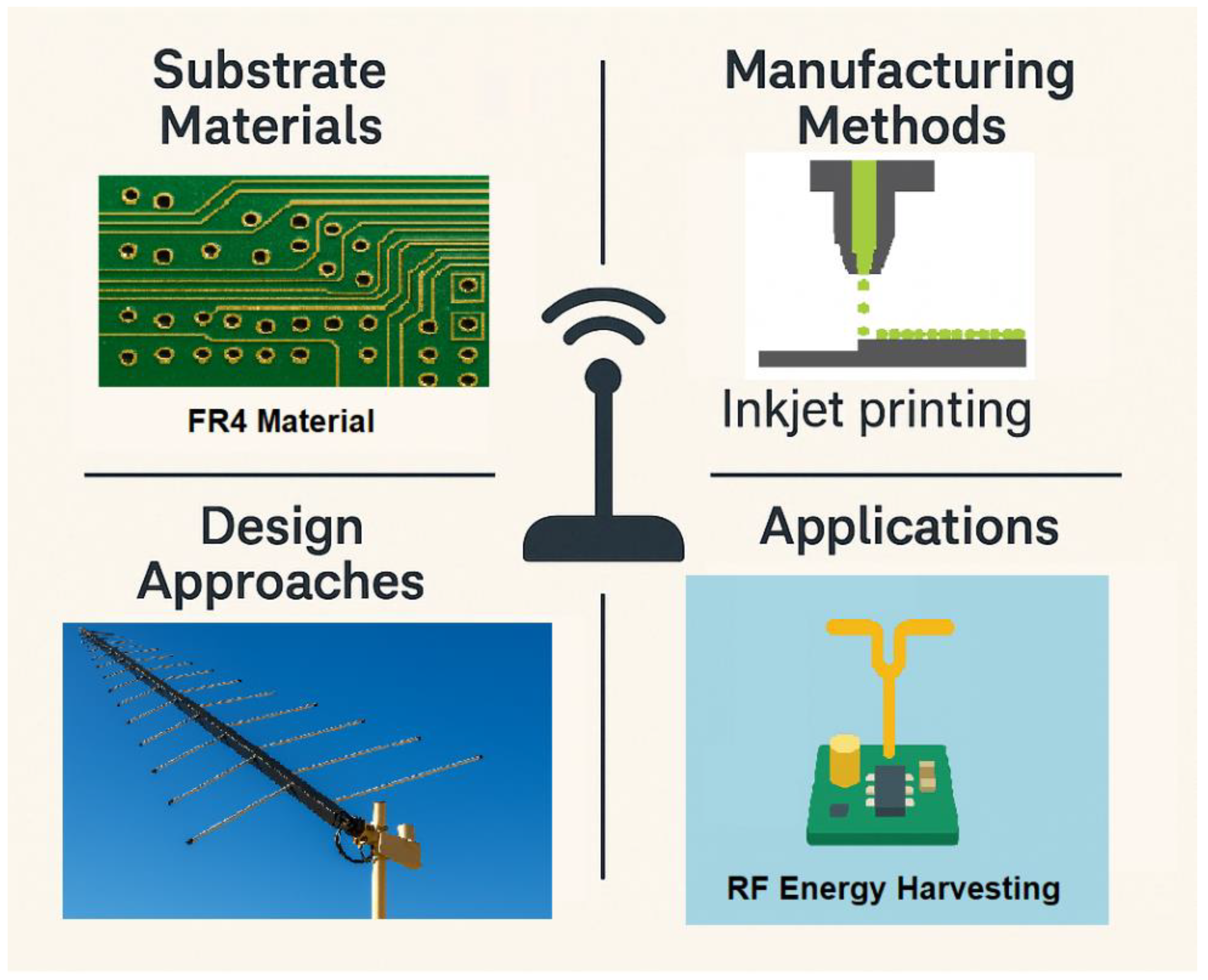
Figure 2.
Overview of 3D Printing Techniques. (A) Fused Deposition Modelling (FDM): (a) Schematic showing filament extrusion through a heated nozzle, (b) Real-time FDM printing of a polymeric structure. (B) Selective Laser Sintering (SLS): (a) Laser sintering pattern on powder bed, (b) Final printed object partially embedded in powder.(C) Vat Photopolymerization Techniques: Comparison between (left) Digital Light Processing (DLP) and (right) Stereolithography (SLA), both using UV light to cure liquid resin layer-by-layer. (D) (a) PolyJet printing using model and support materials with UV curing, (b) Binder Jetting using an inkjet printhead to deposit liquid binder onto a powder bed [3].
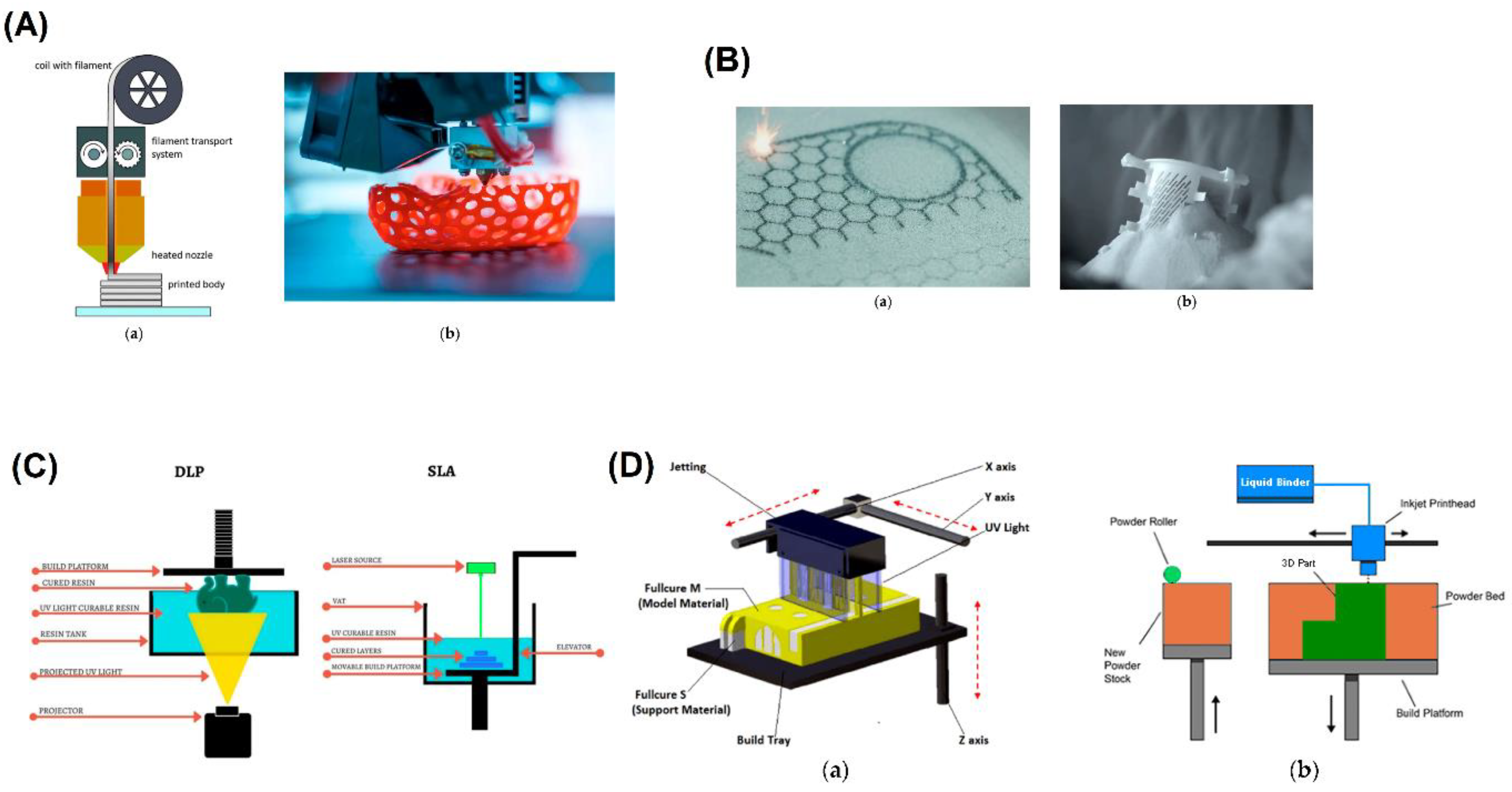
Figure 3.
Analysis of a Wireless Power Transfer System.(A) Fabricated antenna prototypes: (a) Circular microstrip patch antenna, and (b) Rectangular ground plane configuration with corresponding top views.(B) Antenna performance: Variation of radiation efficiency (%) and realized gain (dB) with frequency from 2 to 5 GHz.(C) Impact of impedance matching network (IMN) on RF-to-DC conversion: (a) Efficiency vs. input power (Pin) with and without IMN, (b) Output voltage and power versus Pin.(D) Circuit-level simulation schematic using harmonic balance and parameter sweep to evaluate power conversion performance.(E) Equivalent circuit model of the rectenna showing RF front-end elements including matching, filtering, and rectification components[6].
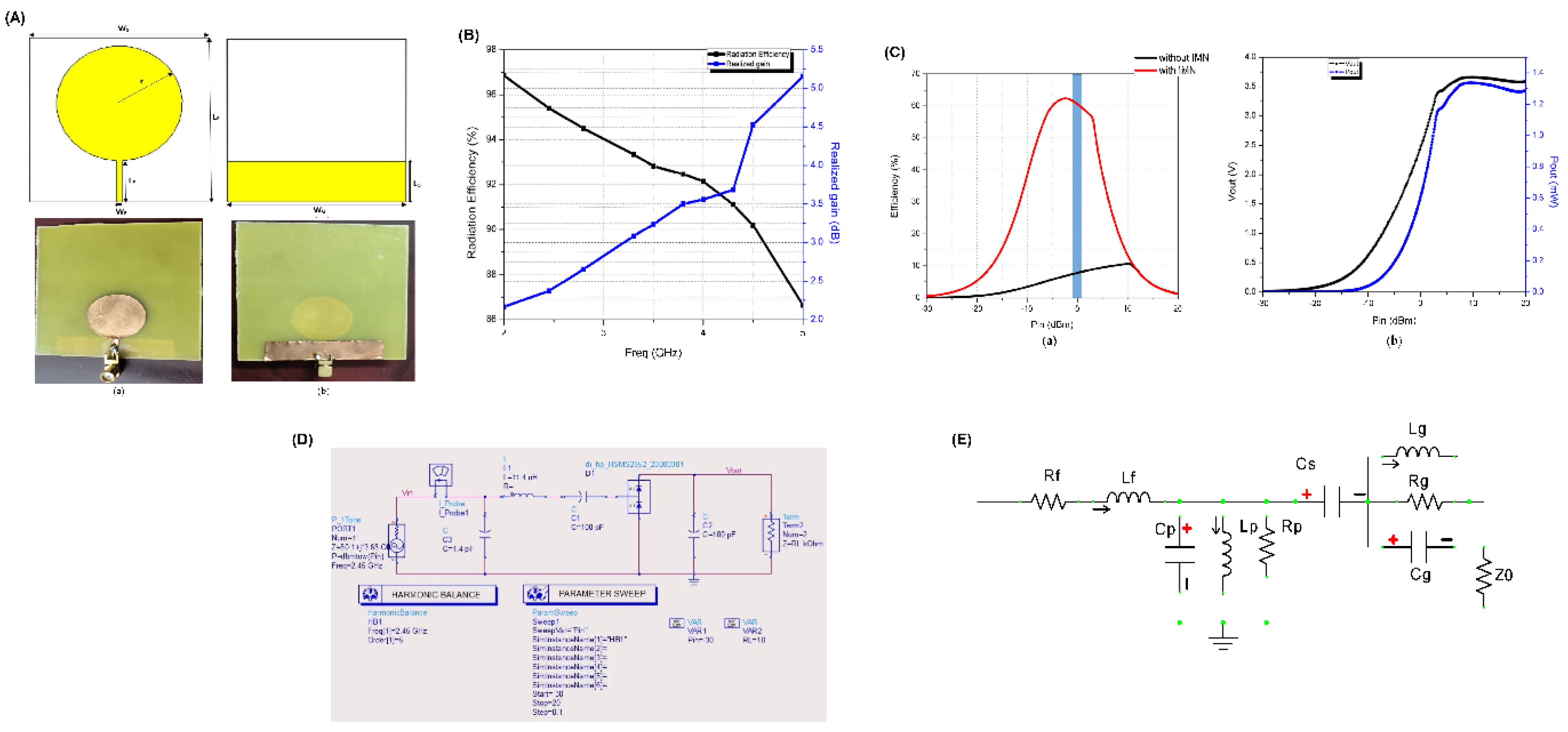
Figure 4.
Design, Configuration, and Performance Evaluation of a Multiband Rectenna for Wireless Power Harvesting.(A) Schematic layout and dimensional details of the multiband antenna structure fabricated on a Rogers 3210 substrate, showing patch, feed, ground, and SMA connector placement.(B) Antenna design evolution: (a) basic patch, (b) initial slot addition, (c) further slot development, and (d) final optimized design for multiband operation.(C) Simulated radiation patterns of the antenna in two principal planes: (a) xoz-plane and (b) yoz-plane, demonstrating directional behavior.(D) Fabricated rectifier circuit using the HSMS 2852 Schottky diode with impedance matching network(E) Performance comparison showing simulated and measured RF-to-DC conversion efficiency and output voltage as a function of input power levels[8].
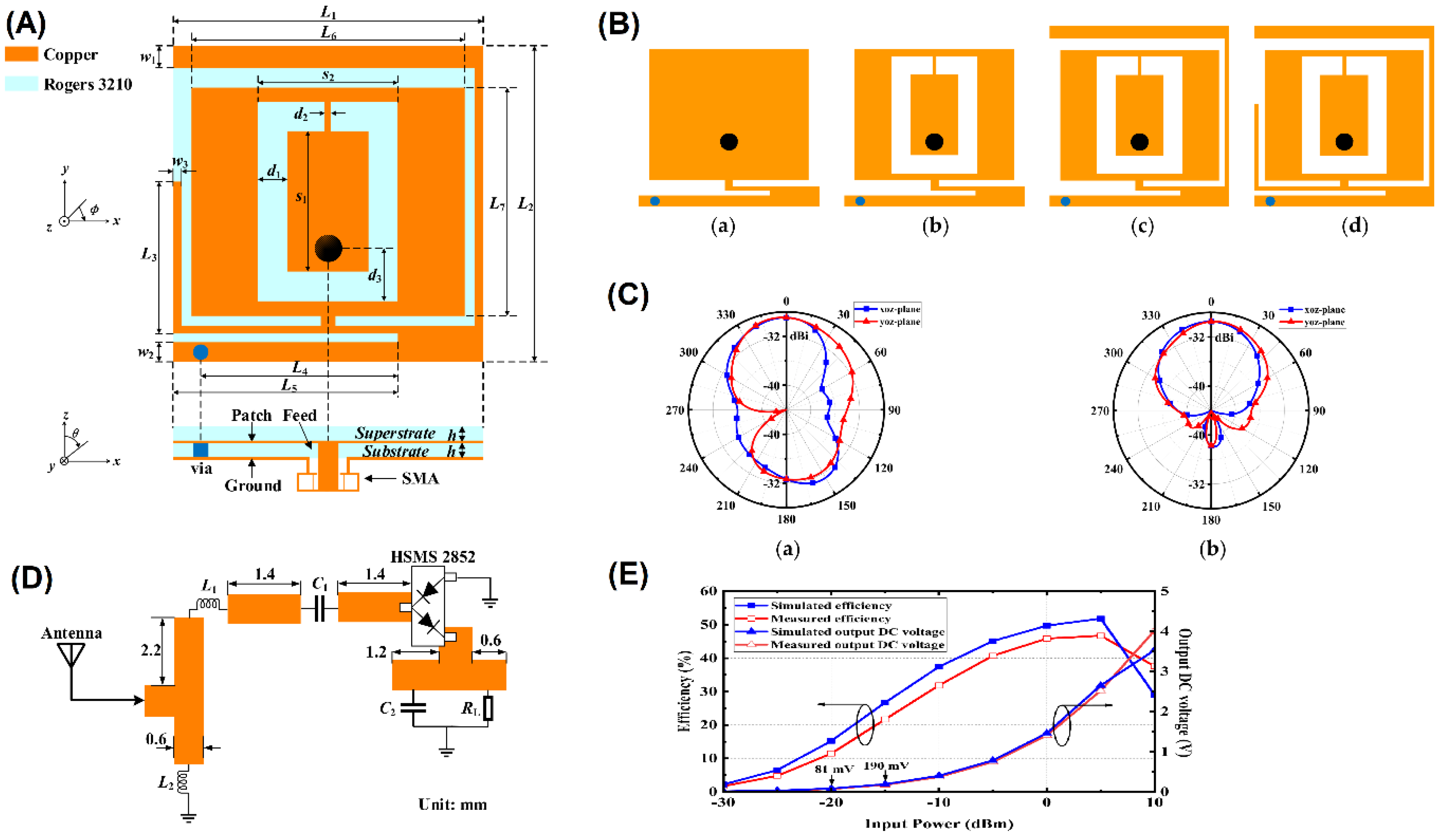
Figure 5.
Design and Performance of a Circularly Polarized Compact Antenna System with Energy Harvesting Capabilities.(A) Schematic diagram of the proposed antenna system: (a) Complementary Split Ring Resonator (CSRR) unit cell, (b) circularly polarized antenna design, and (c) radiator incorporating 18 CSRR elements integrated with a rectifying energy harvesting circuit.(B) Simulated and measured reflection coefficient (S11) performance of the antenna across the 2.4–2.9 GHz frequency range, showing strong agreement and effective impedance matching.(C) Simulated radiation pattern showing gain and directivity at broadside (θ = 0°), with a peak directivity of approximately 7.89 dBi and radiation efficiency of 86.94%.(D) Block-level integration of the energy harvesting and wireless power transmission system including matching networks, rectifier, switch, amplifier, compact battery, and receiver.(E) Fabricated prototype: (a) fully integrated circular polarized antenna with CSRR-based radiator and energy harvesting unit, and (b) zoomed-in view of the etched CSRR structure with a diameter of 11.4 mm[15].
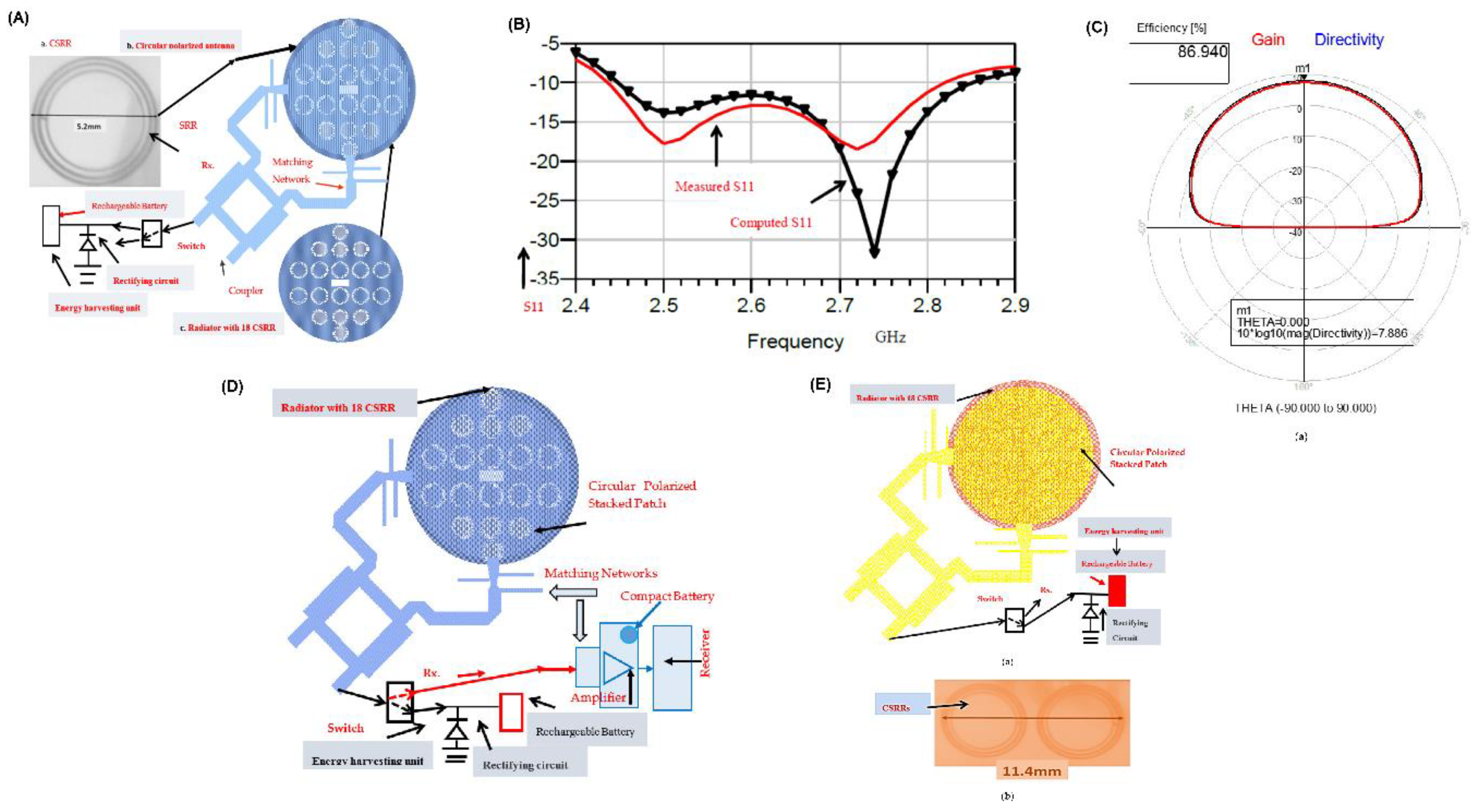
Figure 6.
Hybrid Energy Harvesting and RF Rectenna Design for Enhanced Power Conversion Efficiency.(A) Block diagram of a hybrid energy harvesting system integrating solar and RF energy sources, with MPPT control, rectification, filtering, and storage units.(B) (a) Proposed U-shaped microstrip antenna layout with dimensional parameters, (b) corresponding substrate layout for fabrication.(C) Schematic of the RF rectifier circuit layout with labeled passive components (capacitors, inductors, and diodes) and geometrical parameters.(D) Simulated and measured Power Conversion Efficiency (PCE) vs. input RF power (Pin), highlighting peak PCE near 20 dBm input power.(H) Measured PCE of the integrated hybrid system across varying input power levels, showing maximum efficiency above 85%; inset image shows the experimental test setup for validation[16].
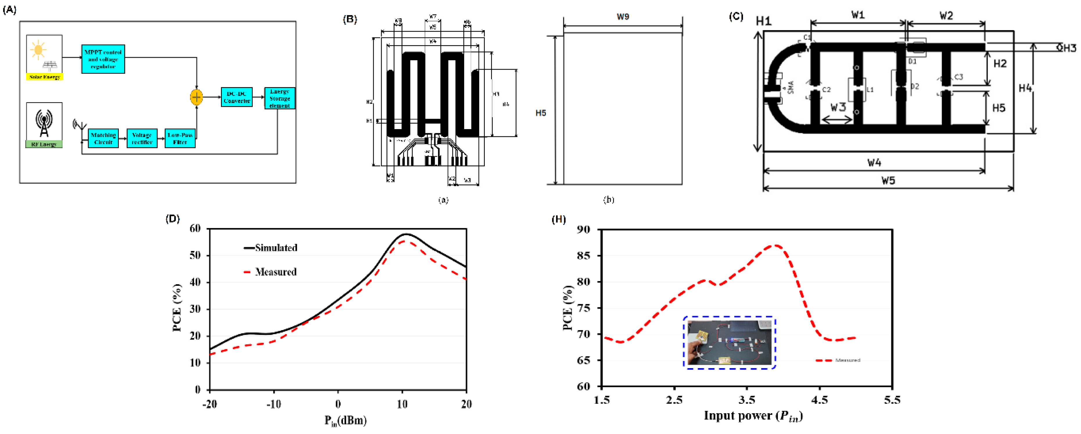
Figure 7.
Design, and Performance Evaluation of a Compact Circularly Polarized Antenna Array with Metasurface Integration.(A) Configuration of the proposed unit cell: (a) Front and side views of the metasurface-based antenna element with detailed structural parameters, (b) mirrored layout variant for polarization control.(B) Parametric analysis showing: (a) transmission coefficient vs. frequency, (b) electric field distribution, (c) reflection coefficient (S11), and (d) axial ratio, for varying structural parameter.(C) Comparison of simulated and measured RHCP gain and radiation efficiency across four operating frequency bands.(D) Simulated performance: (a) Reflection coefficient, (b) axial ratio over frequency, (c-d) RHCP gain patterns across azimuth and elevation planes.(E) Comparison of simulated and measured reflection coefficients for various prototypes across multiple frequency bands, confirming strong agreement and broadband performance[28].
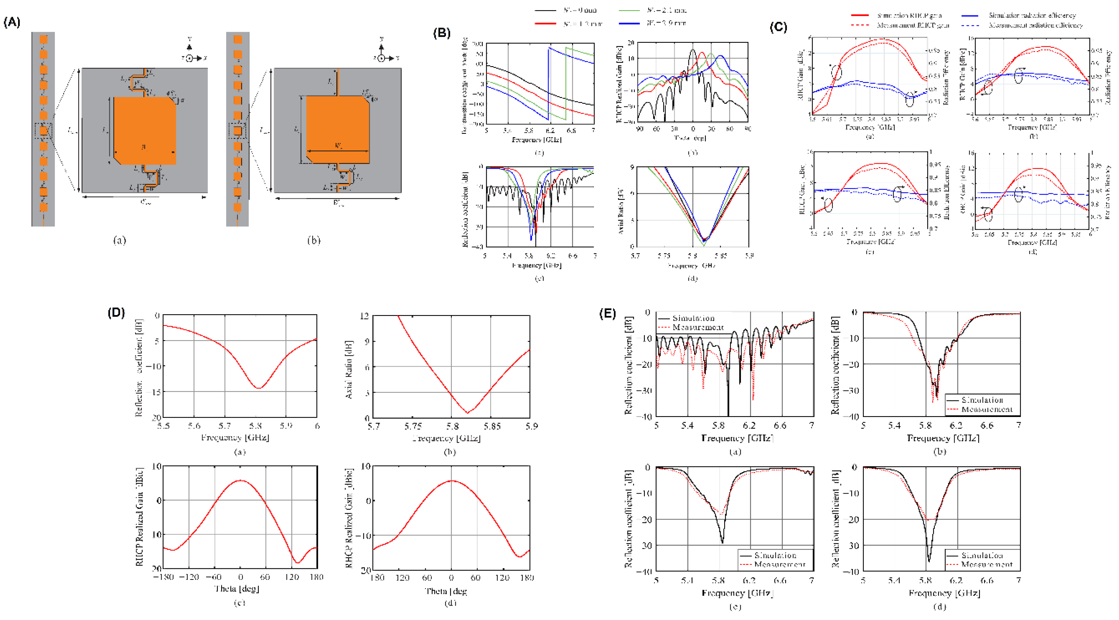
Figure 8.
Design and Performance Analysis of a Dual-Antenna Wireless Power Transfer and Communication System with AMC Integration for Biomedical Applications.(A) Structural views of the proposed monopole antenna with Artificial Magnetic Conductor (AMC) backing: (a–b) 3D and side perspectives, (c) top view with dimensional layout, (d) exploded view showing AMC tile arrangement.(B) Human body modeling for antenna placement: (a) cross-section of arm model showing muscle, fat, and skin layers; (b) antenna placement on the arm with a 138 mm separation between WPT and communication antennas.(C) Geometry of a single AMC unit cell (left) and its periodic 3×3 array (right) for enhancing radiation characteristics.(D) Simulated and measured performance: (a) Reflection coefficient (S11) comparison between standalone WPT antenna and dual-antenna system, (b) transmission coefficient (S21) comparison showing low coupling.(E) Radiation pattern analysis in the presence of a human arm model: (a–b) co-polar and cross-polar gains in different planes, with and without the AMC surface, confirming robust radiation and isolation performance[30].
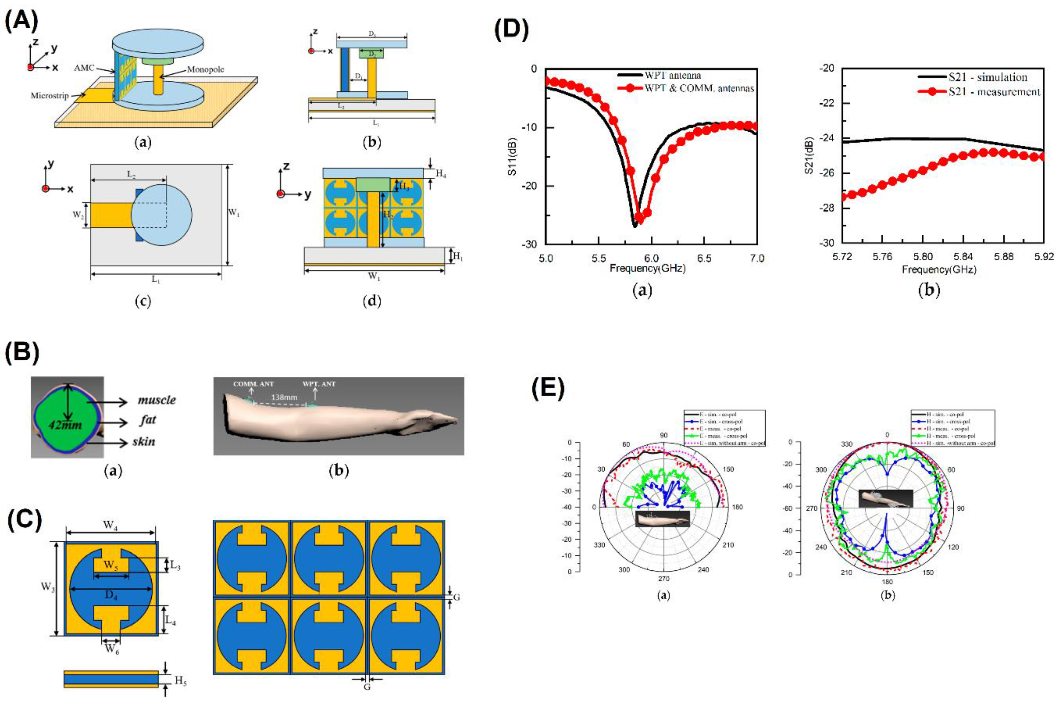

Table 1.
Comparative Overview of Antenna Designs and Techniques for Energy Harvesting Applications.
| Title | Summary | Design | Techniques | Software | Frequency | Bandwidth | Gain | Efficiency | Applications | Sbstrate | Ref |
| Meander Line Antenna for RFID Tags | Lightweight, compact, conformal antenna designed for RFID tags, improving performance with RF ICs. | Meander line, quarter-wavelength structure, 50 Ω excitation, lumped element ports | Impedance matching, T-shape slit, partial ground plane | CST 2019 | 919 MHz | 860-960 MHz | Peak: 3.54 dB | High | RFID tags, ambient RF signal capture | [16] | |
| Implantable Antenna for RF Energy Harvesting and Data Transmission | Dual-band antenna for RF energy harvesting and data transmission, compact design for implantable applications. | Multiple radiating branches, C-shaped slot, voltage-doubled rectifier | Rogers 3210 substrate, superstrate isolation | ANSYS HFSS v.18 | 902-928 MHz, 2.4-2.48 GHz | 0.67-1.05 GHz (44.2%), 2.11-2.96 GHz (33.5%) | Peak: -28.9 dBi, -29.5 dBi | Conversion efficiency: 52% at 5 dBm | Biomedical, RF energy harvesting, data transmission | [8] | |
| IoT Infrastructure Antenna with TEH Integration | Multi-source ambient energy harvester integrating RF and thermal energy harvesting, designed for IoT. | V type dipole, Cantor fractal structure, ABS substrate, aluminum fins | RF and thermal energy harvesting, heatsink integration | Ansys HFSS, Ansys Fluent | GSM900, GSM1800, 3G | Triple-band | Gains: 3.8 dB, 4 dB, 5.3 dB | Radiation efficiency: ~80% | IoT, ambient energy harvesting | [19] | |
| Circular Polarized Antennas for Biomedical, IoT, 5G | Novel circular polarized sensors and antennas for biomedical systems, energy harvesting, IoT, and 5G. | Circular stacked patch, branch line coupler, energy harvesting unit | Microstrip fed, circular split-ring resonators (CSRRs) | Not specified | 2.4-2.9 GHz | 10-20% | 7-8.4 dBi | 87% | Healthcare, IoT, 5G, energy harvesting | [15] | |
| UWB Hilbert-Shaped Metamaterial Antenna | Ultrawide band (UWB) antenna for RF energy harvesting using organic substrates. | Low profile rectangular MTM array, INP substrate, EBG defects | Hilbert-shaped MTM, INP substrate, silver nanoparticle printout | Not specified | 3-10 GHz | UWB | 1.1-3.9 dBi | Not specified | IoT, 5G, WiMAX, RF energy harvesting | [12] | |
| UHF Wire-Mesh Dipole Antenna | UHF wire-mesh dipole antenna optimized for integration with solar panels. | Two rectangular wire mesh elements, 35 cm length, 25 mm × 20 mm mesh size | Copper wire mesh, vertical mesh configuration | Not specified | 350-600 MHz | Not specified | Not specified | 83% total, 88% radiation | Solar panels, energy harvesting | [23] | |
| Hybrid Antenna for RF Energy Harvesting and WPT | Hybrid antenna for simultaneous RF energy harvesting and wireless power transfer. | Dual-polarized omnidirectional and high-gain directional elements | Multiband dual-polarized, directional patch array | Not specified | GSM-1800, UMTS-2100, ISM-2400/5800, 5G-3500, WLAN | Not specified | Not specified | Not specified | RF energy harvesting, wireless power transfer | [20] | |
| Circularly Polarized Broadband Rectenna | CP broadband rectenna for smart city sensing nodes to harvest RF energy. | Semi-cylindrical dielectric resonator, Bow-tie slot | Semi-cylindrical dielectric resonator, microstrip feed, semi-annular slots | Not specified | 5.45-8.34 GHz | 2.89 GHz (Impedance), 680 MHz (CP AR) | 4.8 dBic | 65.20% | Smart cities, RF energy harvesting | [21] | |
| Hybrid Solar and RF Energy Harvesting System | Proposes a hybrid energy harvesting system combining solar and RF energy using tree-shaped antennas. | Tree-shaped antennas, solar cell panel, rectifiers | 3D printed antennas, SMA adaptors, solar panel | N/A | 2.39-2.52 GHz | -10 dB | 6.0 dBi | RF-to-DC: 68.7%; Max harvested power: 52.6% (8 dBm RF); Solar power: 7.3 mW | Hybrid solar-RF energy harvesting | [14] | |
| RF Energy Harvesting System for WSN | New RF-EH system for WSN using switch circuits controlled by input powers. | Multiband meander line antenna, Teflon glass substrate | Schottky diodes, full-wave rectifier, voltage doubler | CST | 1.8 GHz, 2.1 GHz, 2.66 GHz | 13 GHz (1.8 GHz); 15 GHz (2.1 GHz) | 2.7 dB (1.8 GHz); 2.9 dB (2.1 GHz); 2.55 dB (2.66 GHz) | Max RF-to-DC: 71.5%; Max DC output: 5.6 V (open), 3.15 V (2 kΩ load) | Wireless Sensor Networks | [17] | |
| Polarization Insensitive UWB Antenna for EM Energy Harvesting | Develops an UWB antenna with flower petals for IR to UV-visible regime. | Tapered flower petals, SU8 dielectric, nickel and gold layers | Spline curves, 3x3 array | CST Microwave Studio | 25-800 THz | 209.8° (3 dB) | 6.01 dBi | Average absorption: 84.5% | Energy harvesting, THz imaging, broadband signal transmission | [10] | |
| Triple-Band Triangular Patch Antenna for RF Energy Harvesting | Proposes a compact triple-band triangular patch antenna for IoT devices. | Triangular patch resonators, Teflon glass substrate | CST optimization | CST | 2.45 GHz, 5.2 GHz, 8.15 GHz | N/A | 2.58 dBi (2.45 GHz); 4.55 dBi (5.2 GHz); 5.9 dBi (8.15 GHz) | Max RF-to-DC: 77%; Resonant frequencies: -39.5 dB (2.45 GHz), -38 dB (5.2 GHz), -29 dB (8.15 GHz) | IoT devices, RF energy harvesting | [18] | |
| Metamaterial-Based Absorber for RF Energy Harvesting | Compact tilted split ring multiband metamaterial-based absorber for LTE2350, WiFi2450, and LTE2600 bands. | Split ring resonator | Split rings on FR4 substrate, 45° tilt, thin metal ground plane | HFSS | 2.35 GHz, 2.45 GHz, 2.6 GHz | Not specified | Not specified | Not specified | RF energy harvesting | FR4, 1.57 mm thickness | [5] |
| Wideband Circular-Slot Antenna for RF Signal Harvesting | Wideband circular-slot antenna for GSM1800, UMTS2100, Wi-Fi2450, and LTE2600. | Circular-slot antenna | Circular-ring radiating element, circular and rectangular slots | ANSYS HFSS | 1.640-3.150 GHz | 1.59 GHz | 4.32 dBi | Not specified | RF energy harvesting, wireless communication | FR-4, 1.6 mm thickness | [7] |
| Dual-Purpose Radial-Array Rectenna for IoT | Radial-array rectenna for RF-energy harvesting and orientation sensing for IoT nodes. | Radial-array rectenna | Eight radially placed rectenna elements, scoop-shaped antenna, MMSE method | Not specified | 5.8 GHz | Not specified | 7 dBi | Not specified | RF energy harvesting, IoT | Not specified | [22] |
| High-Gain CP Hexagonal Antenna Array for RF Energy Harvesting | High-gain circularly polarized hexagonal antenna array for 5.8 GHz. | Hexagonal antenna array | CP antennas, X-shaped aperture-coupling, FSS, DC combiner | Not specified | 5.8 GHz | Not specified | 12.7 dBi | 67.75% | Wireless power transfer, WSNs | RT/Duroid 5880, foam layer | [9] |
| Wideband mmWave CP Complementary Antenna Array for RFEH | A wideband circularly polarized antenna array for RF energy harvesting at mmWave frequencies. | Planar 4×4 array, Full-corporate SIW network | CP magneto-electric dipole, complementary source technique, SIW network | - | 35-39 GHz | Impedance bandwidth: 20.2%, 3-dB AR bandwidth: 24.3%, 3-dB gain bandwidth: 22.8% | 8.7 ± 1.6 dBic | - | mmWave RF energy harvesting | - | [11] |
| Split Ring Resonator Shaped Monopole Antenna for RFEH | Circularly polarized monopole antenna on FR4 substrate with multiband rectifier circuit. | Size: 15 × 35 mm², Stop band: 2.5-3.5 GHz | Split ring resonator, T-shape slit, voltage doubler rectifier | HFSS, ADS | 2-10 GHz | -10 dB impedance matching: 2-10 GHz | - | 60% | RF energy harvesting for IoT and biomedical devices | FR4 | [24] |
| Chand-Bali Nano-Antenna for IR Energy Harvesting | Polarization-independent nano-antenna optimized for IR energy harvesting. | Dual-polarization, High impedance matching | Adjoint-based optimization, MIM diodes, metallic resonators | - | 10 μm (IR) | - | - | Improved by an order of magnitude | Infrared energy harvesting | Gold, TiO2 | [13] |
| Monopole Receiving Antenna for RF Energy Harvesting | Compact circular patch monopole antenna on FR4 substrate for RF energy harvesting. | Size: Length (LS), Width (WS), Thickness: 0.8 mm, Radius (r) | Microstrip line feed, reduced ground plane | - | 2.06-5.0 GHz | Impedance bandwidth: 2.94 GHz | 2.38 dBi at 2.45 GHz | >86% (95.4% at 2.45 GHz) | Ambient RF energy harvesting, low-power wireless sensors | FR4 | [6] |
Table 2.
Comparative Overview of Antenna Designs and Techniques for Wireless Power Transfer.
| Title | Summary | Techniques | Frequency Bands | Gain | Return Loss | Impedance Matching | Substrate | Applications | Ref |
| Dual-Purpose Circular Patch Antenna for SWIPT | Proposes a circular patch antenna for simultaneous wireless information and power transmission (SWIPT). | Proximity-coupled feed for WIT, capacitive-coupled feeding network with FWR for WPT | WIT: 5.7-6.0 GHz<br>WPT: 5.2 GHz | Not specified | Not specified | Better matching at 2.43, 3.4, 4.56 GHz | Not specified | Energizing IoT sensors, wireless sensor networks (WSN) | [44] |
| High-Efficiency Rectenna for Implantable Medical Devices | Proposes a rectenna with a magneto-electric (ME) heterostructure for IMDs. | ME antenna combined with RF inductive coil | 54 kHz | Not specified | Not specified | PTE: 2.8159% at 15 mm distance | Not specified | Implantable medical devices (IMDs) | [34] |
| Continuous Aperture Antenna for WPT Systems | Design of a 2D continuous aperture antenna for ceiling deployment in WPT systems. | Omnidirectional radiating elements, strategic positioning to avoid mutual coupling | mmWave frequencies | Not specified | Not specified | Efficient power transmission, reduced blockage | Not specified | Office or residential room WPT environments | [25] |
| Power Dividing Rectenna System | Features a circular patch antenna with a 10-way radial power divider. | Via-coupled stacked-substrate, circular PCB laminates | Not specified | Not specified | Not specified | Accurate matching for high power levels | Rogers CuClad217 (εr = 2.2) | WPT, energy harvesting (EH) | [26] |
| 3D Antenna for RFEH and WPT | Presents a cube-shaped 3D antenna derived from a quasi-Yagi antenna (QYA). | Optimized 2D QYA model, CST Studio simulations, GANs for data augmentation | 915 MHz | 11.43 dBi | 45.61 dB | High gain and efficiency | Not specified | RF energy harvesting (RFEH), WPT for low-power devices | [33] |
| Textile-Integrated Circularly Polarized Rectenna for WPT | A 2.4 GHz circularly polarized rectenna for wireless power transfer, integrated into a textile. | Rectangular patch with truncated corners, T-match structure, single-diode rectifier, co-simulation strategy | 2.4 GHz | ~-1 dB | Not specified | High degree of integration, complex conjugate impedance matching | ELITEX 117/f17 2ply threads, polyester threads | Wireless power transfer in textiles | [29] |
| Miniaturized Transmitter Antenna for Implantable Medical Devices | A novel transmitter antenna operating at 1.71 GHz for deep-implant power transfer. | Proximity-coupled feeding, slotted ground, meandering slotted radiator, coaxial feedline | 1.71 GHz | -20 dB (Rx), 5.2 dB (Tx) | -32 dB (Rx) | Excellent impedance matching, minimal back-radiation | Roger 6010 substrate (Rx), Taonic TLY-5 (Tx) | Power transfer to implantable medical devices | [37] |
| Dual-Circularly Polarized Wideband Antenna | Low-cost, low-profile, dual-circularly polarized antenna with wideband capabilities. | Common sub-array aperture, five patch elements, sequential rotation | 2.23-2.80 GHz | Not specified | Not specified | Competitive performances, low axial ratios, cross-polarization levels | Not specified | Satellite systems, wireless communications, DCP wireless power transfer | [40] |
| UWB Phased Array Antenna for UAVs | A 4×4 phased array antenna for far-field WPT to power UAVs. | Impulse radio UWB signals, phased array, slotted patch design | 7.5-8.5 GHz | 20.9 dBi | Not specified | Optimal performance, minimal coupling coefficient, low SLL | FR4 substrate | Far-field WPT for UAVs | [39] |
| Tightly Coupled Dipole Array (TCDA) Antenna | Lightweight, low-cost TCDA antenna for wireless power transfer with improved H-plane scanning. | H-plane scanning booster (HSB), 1-to-4 differential feed network | 4.3:1 impedance bandwidth | 13.73 dBi | Low cross-polarization: -30.5 dB | Wide and consistent scanning range of ±50° | Not specified | Wireless power transfer | [41] |
| Compact Printed Rectenna Circuit | Dual-band rectenna circuit for wireless power transfer at 900 MHz and 1450 MHz. | Rectangular patch antenna, voltage doubler (VD) circuit, impedance matching circuit | 900 MHz, 1450 MHz | Max DC output voltage: 5.318 V (900 MHz), 5.52 V (1450 MHz) | Not specified | PCE: 53% (900 MHz), 54% (1450 MHz) | Rogers RO4003 | Wireless power transfer | [27] |
| Millimeter-Wave Wireless Power Transfer System | 24-GHz beam-steerable multinode WPT system with a new figure of merit (FoM). | 8x8 phased-array transmitter, 5x5 high-gain angle-deflection planar rectennas | 24 GHz | Not specified | Not specified | Beam-steering capability | Not specified | Wireless power transfer, biomedical applications | [35] |
| LIC-Antenna | Flexible, high-conductivity planar-spiral antenna using LDW technique. | Laser direct writing (LDW), programmable design | Not specified | 6.1 dBi | Not specified | High radiation efficiency: 88% | Not specified | Wearable electronics, IoT, smart devices | [31] |
| Series-Fed Antennas | Antennas with circular polarization (CP) on Taconic RF-35 substrate. | U-shaped bends, transmission lines, truncated corners | 5.77-5.88 GHz | 6.2 dBic | -10 dB | Axial ratio bandwidth: 5.81-5.85 GHz | Taconic RF-35 | Wireless power transmission, radar, communication systems | [28] |
| Tattoo-Polymer Antenna | Planar octagonal loop antenna for on-body WPT in the Wi-Fi range. | 3x3 ring-shaped FSS, PDMS substrate, silver epoxy, EGaIn liquid metal | 2.40 GHz | High radiation efficiency | Not specified | Reduced SAR values by 75.5% | PDMS | Wearable electronics | [45] |
| Tightly Coupled Dipole Array (TCDA) Antenna | Lightweight, low-cost TCDA antenna for wireless power transfer with improved H-plane scanning. | H-plane scanning booster (HSB), 1-to-4 differential feed network | 4.3:1 impedance bandwidth | 13.73 dBi | Low cross-polarization: -30.5 dB | Wide and consistent scanning range of ±50° | Not specified | Wireless power transfer | [41] |
| Compact Printed Rectenna Circuit | Dual-band rectenna circuit for wireless power transfer at 900 MHz and 1450 MHz. | Rectangular patch antenna, voltage doubler (VD) circuit, impedance matching circuit | 900 MHz, 1450 MHz | Max DC output voltage: 5.318 V (900 MHz), 5.52 V (1450 MHz) | Not specified | PCE: 53% (900 MHz), 54% (1450 MHz) | Rogers RO4003 | Wireless power transfer | [27] |
| Millimeter-Wave Wireless Power Transfer System | 24-GHz beam-steerable multinode WPT system with a new figure of merit (FoM). | 8x8 phased-array transmitter, 5x5 high-gain angle-deflection planar rectennas | 24 GHz | Not specified | Not specified | Beam-steering capability | Not specified | Wireless power transfer, biomedical applications | [35] |
| LIC-Antenna | Flexible, high-conductivity planar-spiral antenna using LDW technique. | Laser direct writing (LDW), programmable design | Not specified | 6.1 dBi | Not specified | High radiation efficiency: 88% | Not specified | Wearable electronics, IoT, smart devices | [31] |
| Series-Fed Antennas | Antennas with circular polarization (CP) on Taconic RF-35 substrate. | U-shaped bends, transmission lines, truncated corners | 5.77-5.88 GHz | 6.2 dBic | -10 dB | Axial ratio bandwidth: 5.81-5.85 GHz | Taconic RF-35 | Wireless power transmission, radar, communication systems | [28] |
| Tattoo-Polymer Antenna | Planar octagonal loop antenna for on-body WPT in the Wi-Fi range. | 3x3 ring-shaped FSS, PDMS substrate, silver epoxy, EGaIn liquid metal | 2.40 GHz | High radiation efficiency | Not specified | Reduced SAR values by 75.5% | PDMS | Wearable electronics | [32] |
| Wearable Directional Button Antenna for Wireless Power Transfer | Design of a wearable directional button antenna for power transfer on the human body. | AMC cells, monopole antenna, microstrip line feed, textile materials | 5.47-6.11 GHz | Not specified | Not specified | Achieves 180° phase difference | 100% cotton substrate, nickel-copper conductive textile, F4BTM substrate | On-body wireless power transfer | [30] |
| ASW-Tx Antenna Design for Biomedical Implants | Antenna design with anti-symmetric wing plane for biomedical implants. | Taconic TLY-5 substrates, anti-symmetric wing, magnetic dipole, impedance matching network | 1.95 GHz | Not specified | Peak S11: -26 dB | Optimal current directions matched to 50Ω source | Taconic TLY-5 substrates | Biomedical implants | [38] |
| Wide-Band Monopole Antenna for UHF-RFID | Monopole antenna with enhanced impedance bandwidth for UHF-RFID. | Cutting angles, modified feed line | 0.554-1.06 GHz | Peak gains: 2.82 dBi and 2.95 dBi | -38.4 dB at 868 MHz, -25.3 dB at 915 MHz | Enhanced impedance bandwidth, improved matching and coupling | Not specified | UHF-RFID applications | [43] |
| Polarization-Insensitive Rectenna for WPT | Metasurface-based rectenna design for polarization insensitivity in WPT. | Octagonal metal ring, meandered groove | 5.8 GHz | Maximum: 66% | Not specified | Improved rectifier efficiency by 1%-4% | Not specified | Wireless power transfer | [36] |
| Wireless Power Transfer System with Beam Steering | Design of a WPT system with beam steering for indoor settings. | 1D microstrip patch antenna array, ESP-32 module, charge-pump rectifier | 2.4 GHz | TX: 4.4 dBi, RX: 4 dBi | Not specified | Quarter-wave transformer for optimal matching | Microstrip patch antenna | Indoor wireless power transfer | [42] |
Disclaimer/Publisher’s Note: The statements, opinions and data contained in all publications are solely those of the individual author(s) and contributor(s) and not of MDPI and/or the editor(s). MDPI and/or the editor(s) disclaim responsibility for any injury to people or property resulting from any ideas, methods, instructions or products referred to in the content. |
© 2025 by the authors. Licensee MDPI, Basel, Switzerland. This article is an open access article distributed under the terms and conditions of the Creative Commons Attribution (CC BY) license (http://creativecommons.org/licenses/by/4.0/).
Copyright: This open access article is published under a Creative Commons CC BY 4.0 license, which permit the free download, distribution, and reuse, provided that the author and preprint are cited in any reuse.


