Submitted:
12 June 2025
Posted:
13 June 2025
Read the latest preprint version here
Abstract
In the first part of this study, we investigated the coefficient of performance (COP) of a commercial TEC1-12706 thermoelectric module inside a cooling box made from expanded polystyrene with air as the load medium. The cooling tests were performed under forced–air convection, with heat transfer assemblies formed by two pin–fin heat sinks and three different fans for the air ventilation of the external heat sink. An optimal air ventilator for the external heat sink was selected to assess the cooling performance of three different commercial thermoelectric cooler (TEC) devices during the second stage of testing. Thermoelectric coolers type TEC1 – 12703, TEC1 – 12705 and TEC1 – 12706 were considered for this purpose. Exergy analysis provided the opportunity to investigate the variation in exergy efficiency and thermodynamic irreversibility of thermoelectric cooler devices at different TEC cold–side temperatures, starting from the total entropy generation rate of the TEC module. The optimum TEC1 – 12705 cooling module achieved maximum exergy efficiency values of 0.09 and irreversibility values between 21.2 W and 20.8 W at cold–side temperatures ranging from 3.8 °C to 6.5 °C. In the final part of this study, a 100 ml water glass was considered as a cooling load for the refrigeration system with the TEC1 – 12705 device. We evaluated the coefficient of performance of the overall refrigeration system, which includes the TEC module and ventilation fans as having values between 0.155 and 0.159 over 160 minutes of testing.
Keywords:
heat dissipation rate
; thermal resistance
; entropy
; irreversibility
; exergy efficiency
; coefficient of performance
1. Introduction
Refrigeration plays a vital role in various applications, including the preservation of perishable food products and the control of cooling temperatures in electronic systems [1]. Conventional domestic refrigerators typically utilize vapor-compression technology. While this technology presents a high coefficient of performance (COP), the refrigerants used in these systems can have adverse environmental effects. In contrast, thermoelectric refrigeration, which is based on the Peltier effect, offers significant advantages over traditional vapor compression technology, even though its COP is not as high [2,3]. These benefits include the elimination of refrigerants, a more compact system design, reduced noise and vibration, enhanced temperature control through the variation of their power supply, and minimal maintenance requirements. Moreover, thermoelectric systems can be conveniently powered by direct current (DC) sources, such as photovoltaic cells [4].
Thermoelectric cooling (TEC) technology is gaining popularity for use in small and portable refrigeration systems, particularly in scientific laboratories where a constant temperature bath is necessary [5]. This technology effectively cools and maintains the temperature of samples at a specific set point. Thermoelectric cooling devices have found interesting applications in the medical field, serving as the cooling element in the cryoprobes used for cryosurgery, as well as being used for cooling the brain or skin [6]. Additionally, they are employed in cryotherapy systems where precise control of skin blood flow is required [7].
The heat generated by a thermoelectric module must be extracted from the cooled environment and expelled to the external surroundings. Achieving the necessary level of heat dissipation requires radiator types with sufficient heat transfer capacity. This process is typically facilitated by forced air cooling with pin–fin heat sinks [8,9]. To decrease the thermal resistance of the hot-side heat sink, specific types of heat exchangers, such as heat sinks with phase change materials [10] and heat pipe cooling [11] or those using nanofluid liquid cooling [12] have been employed, offering, in some applications, a very low thermal resistance of 0.02 °C/W. Those heat sink cooling devices proved to increase (by more than 10%) the overall coefficient of performance values of refrigeration systems. This improvement is achieved at higher system costs, accompanied by increased energy consumption.
When selecting an air conditioning system based on thermoelectric devices for a particular application, it is important to evaluate not only the TEC coefficient of performance and the required cooling capacity at the desired temperature. We must take into consideration also the operational characteristics of the cooling system and overall energy consumption, with various types of losses associated with the thermodynamic process of heat transfer at the cold and hot side of TEC. Jurkans and Blums [13] investigated a practical method to increase the efficiency of thermoelectric cooling. They experimentally validated a simple model that evaluated the induced heat loss and the recovered energy after a dynamic switch of the thermoelectric module between cooling and electrical energy generation modes.
From a thermodynamic point of view, the second law analysis and Entropy Generation Minimization (EGM) method has proved to be very powerful tools in the optimization of TEC systems, with the evaluation of the minimum system irreversibility and maximum exergy contribution at a constant environmental temperature [14,15,16]. Tipsaenporm et al. [17] analyzed the thermodynamic properties of a compact thermoelectric air conditioner using an exergy analysis approach. They found that the exergy efficiency of the cooling system was relatively low compared to its coefficient of performance. Many TEC-based cooling system studies have been focused on maximising cooling capacity and coefficient of performance for the overall refrigeration system, improving exergy efficiency as the temperature difference between the TEC hot and cold side’s increases. The optimal performance of a single-stage TEC can be achieved by adjusting both the operating current and the TEC's configuration [18].
The practical purpose of this refrigeration box is to serve as a cooling medium, providing a viable and cost-effective alternative to the expensive thermostatic water bath. We propose enabling the efficient extraction of phenolic compounds from hydroalcoholic mixtures of various fruits and leaves at optimal temperatures of approximately 10°C using the ultrasound-assisted extraction (UAE) method [19,20,21]. We will modify the upper section of the refrigerated box to accommodate the insertion of an ultrasonic transducer, which will be in direct contact with the liquid sample contained in a 100 ml glass placed inside the box. For the current refrigeration test with a water load, we aim for a liquid cooling point of 12°C inside the refrigeration box.
2. Thermal Analysis of the Heat Sink
It was considered here the heat transfer by forced air convection through a system of N parallel plates (having a specific thermal conductivity) placed on a horizontal plate in contact with the heat source, having the geometric characteristics shown in Figure 1.a. The horizontal base plate is considered to be relatively thick compared to the vertical fins and characterized by a high thermal conductivity, so that the plate is treated as isothermal. The bottom surface and edges of the horizontal plate will be considered adiabatic.
The air flux flowing through the channels formed by the fins is considered as uniform, with a constant velocity Ua, without any "leakage" outside the channel edges. The analytical model of the heat sink is based on (N – 1) parallel plate channels, with a single channel defined as seen in Figure 1.b. Here, the air flux having an inlet velocity Ua , at specific ambient temperature Ta , will flow under forced convection through the channel of wall temperature Tw.
The fluid flow field is considered to be two-dimensional for b << H. For a uniform temperature Ts of the base plate (having the thickness Ht – H), we impose a boundary condition Tw = Ts for each of the channel walls. Next, we will use the fin dimensions and thermal conductivity to evaluate the rate of heat transfer from this ideal channel (presented in Figure 1.b), estimating afterwards the actual heat transfer rate of heat sink.
were νa (m2/s) represents the air kinematic viscosity.
If we know the volumetric flow rate of air Va (m3/s) circulated by a fan through the heat sink fins, we can calculate the average velocity of air flux with the following expression [23]:
The channel dimensions will be correlated with the Re number defined by relation (2) to express the Re number for each channel [22]:
The goal of developing heat sink configurations with H >> b is to maximize the available fin surface area, a goal that is often achieved by compromising the fin efficiency. When H >> b, the temperature difference between the fins and the horizontal plate increases due to the increase of the heat conduction resistance, and the performance of the radiator will decrease. During the air forced convection, the heat is removed faster from the fins, comparing with the amount of heat removed from the horizontal plate of the radiator. From this reason, it was considered here a composite solution based on the limit cases of fully developed or under developing air flow between isothermal parallel plates [22].
An ideal value of the average heat transfer coefficient hi (W/m2K) will be associated with an ideal Nusselt number value Nui and with the air thermal conductivity ka (W/mK) through the relation [22]:
In expression (6), Pr represents the Prandl number, calculated with relation:
were μa (Kg/m∙s) and Cp,a ( J/KgK) are dynamic viscosity and specific heat of air.
Under this composite model of air forced convection through parallel plates of the heat sink, the fin efficiency can be expressed as [22]:
were ks (W/mK) is the fin thermal conductivity, with a value of 220 W/mK for the Aluminium Alloy EN AW-6060 [22].
We can see in relation (8) that the decrease of the ratio H/b (or H/t) would reduce the thermal resistance through the fins, and η can approach the ideal value of 1.
The real value of the Nusselt number will be defined as [22]:
According to the composite model, the real heat transfer coefficient for air under forced convection is calculated as [22]:
The total heat dissipation rate of the heat sink, denoted as QHS (W), is determined under the assumption of uniform heat transfer coefficients for both the base plate and the fins, in accordance with the relation provided in [24]:
with ΔTsa = Ts - Ta as the surface-to-air temperature gradient.
In relation (11), M and N are dimensionless parameters, defined through specific expressions:
The surface area of the base plate is given by Ab = W∙L, while the perimeter and cross-sectional area of the heat sink fins, P (m) and Ac (m2), respectively, are calculated with relations:
3. Thermodynamic Modelling of Thermoelectric Cooling System
3.1. Thermal Model of the Refrigeration System and Energy Analysis
The mathematical model presented in this study for analyzing the thermodynamic behavior of a thermoelectric cooling system considers one-dimensional energy balance and heat transfer equations applicable to air-cooled heat exchangers. We considered some assumptions for the model simplification [25]: (i) heat transfer between the hot and cold sides of the thermoelectric cooler (TEC) is one-dimensional and occurs under steady-state conditions, (ii) the Thomson effect is neglected, and (iii) the Seebeck coefficients, electrical resistivity’s and thermal conductivities of the p-type and n-type thermoelectric materials are assumed to be constant, determined at a specific operating temperature.
Figure 2 presents the thermal resistance network diagram of the thermoelectric refrigeration system, considering the thermal resistances imposed by the hot – end and cold -end heat sinks, the TEC module and the thin layers of thermo-conductive paste between the heat sinks and ceramic plates of TEC device.
The total thermal resistance of this refrigeration system is calculated as:
The thermal resistance of the TEC module, RTEC (0C/W), was calculated here with the following relation [25]:
In relation (16), the maximum operating voltage and current Umax and Imax, respectively, the maximum value of the temperature gradient between the hot and cold plates of TEC, ΔTmax , identified at a specific hot – side temperature TH,ref, are all obtained from the datasheets of thermoelectric devices.
The Fourier law of heat conduction was considered here for the calculation of thermal resistance of the silicon – type conductive paste:
For a conductive paste thickness tcp = 0.2 mm with thermal conductivity kcp = 1.2 W/moC and a cross section area of TEC ceramic plates Ap = 16∙10-4 m2, Rcp = 1.04 oC/W.
Thermal resistance of the heat sink at the hot and cold surface of thermoelectric module, RH and RC, respectively, can be evaluated with relations [26]:
In relations (18) and (19), TH and TC represents the hot – side and cold – side TEC temperatures; Tr and Ta are the air temperature inside the cooling box and the ambient air temperature outside the refrigerator system, respectively. TH, TC, Tr and Ta are measured according to the specific experiment stage.
The total amount of heat absorbed at the TEC cold plate, QC (W), is calculated with the following expression [8,27]:
The amount of heat transferred to the heat sink from the TEC hot plate, QH (W), is expressed as [8,27]:
In the relations above, It is the current absorbed by the TEC module from the power supply. The three physical property parameters of the thermoelectric device, Sm, Rm and Km represent the Seebeck coefficient, electrical resistance and thermal conductivity, respectively.
The values of Sm, Rm and Km are estimated from the specific performance curves provided in each of the datasheets of TEC devices used in this study: TEC1-12706, TEC1-12705 and TEC1-12703 [28,29,30]. Three sets of curves are considered, for a standard TH = 27oC: QC as a function of thermal gradient ΔT between the TEC plates at different current values I, Voltage U as a function of ΔT for different current values and Qc as a function of voltage U at different ΔT values.
From the slope of U - ΔT curves at ΔT = 0, selected for current values I as close as possible to the experimentally measured It , we could obtain Rm =U/I (Ω) for each of the TEC devices.
The Seebeck coefficient is evaluated considering the expression [31]:
were TC = TH so ΔT = 0 and the only independent variables are Qc and I. The value of Sm is obtained by considering the pair of values (QC, I) at ΔT = 0 for I ≈ It.
Finally, the thermal conductivity of the TEC module will be calculated by considering a pair of values (I, ΔT), extracted from the curve associated with QC = 0, using the relation [31]:
The values of Sm, Rm and Km obtained for TEC1-12706, TEC1-12705 and TEC1-12703 devices are presented in Table 1.
The power consumption of the thermoelectric module, necessary for system cooling, is assessed as described in [8]:
The first term in equation (24) corresponds to the total Joule power losses, while the second term represents the contribution of the Seebeck effect.
The refrigeration performance of thermoelectric cooler module is investigated through the Coefficient of Performance (COP), defined as a ratio between the cooling capacity of TEC and his power consumption [4]:
3.2. Exergy Analysis
The entropy generation inside a thermodynamic system represents a measure of the irreversibility for a mass and/or heat transfer process [32]. Thermodynamic losses and the inefficiencies present inside an energy transfer system can be quantified through the exergy analysis, a fundamental tool for the evaluation and improvement of the global efficiency of the system. Exergy represents a thermodynamic property which determines the quality of all the energy flows along the system, from inputs to outputs.
The thermal conductance and internal electrical resistance of the thermoelectric materials, in conjunction with a finite heat transfer rate between the TEC module and heat sinks will contribute to an increase of the entropy generation [16]. The heat transfer between the hot plate of TEC and heat sink, the convective heat transfer between the heat sink and surroundings, along with the electrical charge transport between the hot and cold plate of thermoelectric module will generate the occurrence of external and internal irreversibilities and the enhancement of entropy generation rate.
The exergy balance inside the thermoelectric cooling system was expressed as [33]:
were T0 is the environment temperature and Pin = Pt , representing the 100% exergy input [33].
In the right hand side of the relation (26), the first term represents the exergy collected at the cold side of TEC module, being the reversible work inside the cooling system and the third term is the exergy removed from the TEC hot – side; the second term is the system irreversibility (energy destruction), defined as [33]:
were the total entropy generation rate of TEC module, Sgen-T, is defined as below [34]:
The lowest feasible temperature of heat rejection for the thermoelectric cooling system is the environment temperature [15], so T0 = TH.
The exergy efficiency of the thermoelectric cooler, known also as the second – law efficiency, will be defined as the ratio between the exergy output and energy input, using the relation [34]:
4. Performance Analysis of the Thermoelectric Cooling Unit
The main purpose of this air – cooled thermoelectric refrigeration investigation is to establish the cooling performance of the system with an optimal TEC module in the presence of a cooling load. For this purpose, a 100 ml Berzelius glass was placed inside the cooling box.
The coefficient of performance for the entire refrigeration system was calculated with expression [35]:
were We is the total electrical power consumed by the cooling system, and QT (W) represents the refrigeration load (total heat rate developed inside the cooling box), evaluated with relation [35]:
In the relation above, Qcb (W) is the heat flux through the cooling box, Qpl (W) is the product load as the heat removed by the water glass in the refrigerator and Wfan (W) is the electrical power consumption of the external and internal system fans.
In relation (35), m (g) is the mass of the water product, Cp (J/g∙K) is the specific heat capacity of water product, Tp,i and Tp,f (K) are initial and final temperatures of the water product, respectively, and Δt (s) is time interval for the water cooling from Tp,i to Tp,f .
In expression (36), A (m2) is the internal surface area of the cooling box and U (W/m2K) is the overall heat transfer coefficient, defined as [35]:
with the wall thickness and thermal conductivity of the polystyrene – based cooling box, dcb = 4cm and kcb = 0.035 W/mK, respectively.
The heat transfer coefficient at the inner and outer surface of the refrigeration system, hint and hout, respectively, are calculated based on relations (5) – (10), with the geometrical parameters for the external and internal heat sinks presented in Table 2.
All the heat sink dimensions were measured using a digital caliper with resolution of 0.01 mm and accuracy of 0.03 mm.
5. Experimental Set-Up
Two different configurations of thermoelectric cooling systems were considered here. The first one, presented in Figure 3, contained the cooling box with air load and was used for the performance evaluation of three different cooling fans (placed on the external heat sink) and also of three different thermoelectric cooling modules. For the second configuration, presented in Figure 4, we considered a water glass of 100 ml as a cooling load for the refrigeration box.
We used here a server station cooling FAN 8025 DC 12V – 0.4 A (Jin Li Jia Electromechanical, China) with a rotation frequency of 4200 revolutions per minute (RPM) and a circulated air flow volume of 53 cubic feet per minute (CFM), one LHR SUPPER FAN DC 12V – 0.218 A (Shenzen Linghairui Technology, China) having 3000 RPM and 41.2 CFM and a EF80251B3-1000U-A99 12V – 0.78W cooler (Sunon,Taiwan), having 2600 RPM and 33 CFM. The cooling air inside the box was circulated by a small DC brushless fan (Dongguan HYJ, China) 12V-0.1A, with 6200 RPM and 6.86 CFM, placed on the internal heat sink.
As we can see in Figure 3 and Figure 4, experimental cooling system contains a cooler box made from expanded polystyrene, with the inner dimensions of 26 x 20 x 9.5 cm and the wall thickness of 4 cm. Temperatures at the surface of TEC hot plate TH, TEC cold plate TC, refrigerated air inside the box Tr, ambient temperature Ta and water load inside the glass Tp were measured using a four - channel PerfectPrime TC0304 digital thermometer (resolution of 0.1oC and accuracy of ± 1oC), with K-type thermocouples as temperature sensors. The power supply for the TEC module, external and internal fans, PTEC, Pf,e and Pf,i, respectively, was provided by a 300W MCH – K310D DC source (± 0.5% voltage/current display accuracy). Two Kafuter K – 523 thin films of thermally conductive paste with a thermal conductivity of 1.2 W/mK, placed between the hot/cold plate of TEC module and external/internal heat sinks, offered a maximization of heat transfer between the metallic/ceramic surfaces.
Experimental temperature data were recorded through a USB connection between the thermometer and PC using the TestLink TC0309 software.
We tested thermoelectric coolers type TEC1 – 12703, TEC1 – 12705 and TEC1 – 12706, based on 127 bismuth telluride (Bi2Te3) semiconductor couples ( n - type and p – type), with similar dimensions LxWxH (mm) : 40 x 40 x 3.8 (0.1) mm, characterized by different thermo - electrical parameters (see Table 1). In the datasheets, the maximum values of the voltage, DC current and cooling capacity, Umax, Imax and Qc,max, respectively, are specified for a maximum temperature gradient ΔTmax = 70oC, at a hot side temperature Th0 = 27oC.

6. Results and Discussions
In the first part of this study, we conducted cooling tests of 8 minutes duration using a commonly used TEC module for commercial freezing boxes, TEC1 -12706 and three different fans for air ventilation of the external heat sink. During all the investigations presented here, DC power supply of the entire refrigeration system was set to a voltage of 12 V.
The average electrical power consumption (Pf,e) for the three external cooling fans: FAN 8025, LHR, and SUNON was measured at 4.56 W, 2.59 W, and 0.85 W, respectively. For the internal fan, the average power consumption was Pf,i = 0.661 W.
Table 4 below presents the mean values (± standard deviation) for the main thermo-hydraulic parameters evaluated during the tests of the external heat sink under various forced air convection conditions.
Increasing the Reynolds number Re inside the turbulent flow regime (at values over 4000) will reduce the junction temperature between the heat sink and the TEC module. This way, we can improve the heat transfer rate by reducing the thermal resistance at the heat sink/TEC interface. From Table 3, we can see that the mean Re value registered during the SUNON cooler testing was close to the lower limit of the turbulent flow region. Therefore, this type of cooler is not a good choice for the present refrigeration application.
The Nusselt number (Nu) quantifies the convective to conductive heat transfer ratio. So, the highest Nu value registered in the case of FAN 8025 cooler testing indicates the most decisive influence of convective mechanisms within the heat exchange process. A higher Reynolds number is one of the primary factors contributing to an increase in Nu, which intensifies the convective heat transfer between the airflow and the heat sink [36].
We measured the cooling system temperatures TH, TC, and Tr during three different tests of 8 minutes duration at an average external air temperature Ta of 24 oC. The results are presented in Figure 5. In the case of FAN 8025 cooler testing, for the last measurement point, the TEC hot side temperatures TH decreased by about 40 %, along with a decrease of refrigerated air temperature Tr by over 33 % by comparing with LHR cooler testing. Consequently, the heat transfer coefficient hb was about 12 % higher (see Table 4).
In Figure 6, we present the variations in the heat dissipation rate of the external heat sink equipped with the different cooling fans. Under similar surface-to-air temperature gradients, ΔTsa = TH - Ta, recorded during the LHR and SUNON tests (see Figure 5), the heat sink using the LHR cooler showed the highest QHS values. This behavior can be attributed to slightly increased heat transfer coefficients (hb values), as detailed in Table 4. Conversely, the heat sink test with FAN 8025, which had the highest hb values but much lower ΔTsa values, resulted in the lowest QHS values, offering the most efficient air cooling inside the refrigeration system.
In the second stage of the study, we investigated the cooling performances of three different commercial TEC devices inside the same cooling box with an air load and an optimal air ventilator for the external heat sink (FAN 8025 cooler). The average electrical power consumption (PTEC) of the three thermoelectric module modules, TEC1 - 2703, TEC1 - 12705 and TEC1 - 12706, indicated by the power supply at the beginning of each test was 28.18 W, 34.65 W and 53.19 W, respectively.
Figure 7 presents the variations in time for the hot side – cold side temperature gradient of the TEC modules, ΔTHC = TH – TC. We could observe a slight increase with about 1oC of ΔTHC in the case of TEC1- 12705 testing by comparing it with TEC1- 12706 testing during the last 3 minutes.
Figure 8 shows the cooling performance of the TEC1 - 12706, TEC1 - 12705 and TEC1 - 12703 modules and also the variation of the thermal resistances inside the refrigeration system at different temperature gradients between the hot and cold side of thermoelectric modules.
Under a much higher current absorbed from the power supply It, TEC1 - 12706 offered an enhanced cooling capacity for the refrigeration system compared with TEC1 - 12705, presenting this way QC values about 10 W higher (see Figure 8.a). Instead, the increased Joule power losses registered for TEC1 - 12706 generated a power consumption with about 24 W higher than for TEC1 - 12705, so his corresponding COP cooling parameter decreased with 27 % after 8 minutes of testing. Although TEC1 - 12703 presented the lowest cooling capacity, this module showed also the lowest power losses through Joule effect and the COP values were closer to the TEC1 - 12705 module (see Figure 8.b).
Chang Y. W. et al. [37] showed that a thermoelectric air-cooling module presents a lower performance compared to a conventional heat sink without a TEC when the thermal resistance of the heat sink exceeds 0.385 oC/W. Figure 8.c revealed a proper performance of the heat sink under forced air convection, coupled with all the three TEC modules. Due to the high amount of heat transferred between the TEC1-12706 hot side and the heat sink, the RH value was the lowest for this system configuration. For example, at ΔTHC = 30°C, RH was only 0.072 °C/W.
As we can see in Figure 8.d, the total thermal resistance of the cooling system with TEC1 - 12706 presented the lowest values, under a lowest individual thermal resistance RTEC and also the lowest heat sink thermal resistances at the hot and cold junction of TEC module.
The coefficient of performance (COP) of a complete cooling system, which includes both heat supply and heat dissipation subsystems, is influenced by temperature drop losses across the system thermal resistances [38]. Consequently, the COP of the entire thermoelectric cooling unit should be lower than that of an individual TEC module operating under the same ΔTHC conditions.
Under those circumstances, the exergy analysis became necessary to take into account all the losses and inefficiencies registered during the energy conversion process developed inside the refrigeration system.
The total entropy generation rate Sgen inside the cooling system is directly correlated with the internal and external irreversibilities. Internal irreversibilities arise from Joule heating losses due to electrical resistance and heat conduction losses within the thermoelectric couples. External irreversibilities result from irreversible heat transfer between the TEC and the heat source's hot junction and between the TEC cold junction and the heat sink reservoirs [39].
The required refrigeration temperature and a specific cooling capacity play crucial roles in determining the practical applications of thermoelectric cooling systems. Therefore, we present in Figure 9 the variations in the thermoelectric module's exergy efficiency (ηex) and irreversibility (Irr) measured at different cooling temperatures throughout the entire testing period.
During the air cooling test, TEC1- 12705 and TEC1 - 12706 exhibited similar values for TC and TH. However, the QC value recorded for TEC 12706 was significantly higher, with the QH value being 71% to 86% greater. As a result, the entropy generation rate (Sgen) during the testing of TEC1 - 12706 was 0.076 W/K higher than that of TEC1 - 12705. Consequently, as illustrated in Figure 9.a, the irreversibility rate for TEC1 - 12706 was twice as high as that for TEC1 - 12705.
Equation (32) shows that a key factor affecting the exergy efficiency coefficient is the ratio of cooling efficiency to the power consumption of the TEC module. During testing, we found that the Qc/Pt ratios for TEC1 - 12706, TEC1 - 12705, and TEC1 - 12703 were 0.71, 0.91, and 0.92, respectively. Consequently, the exergy efficiency of TEC 12705 was approximately 7.3% higher than that of TEC1 - 12706 at a temperature TC = 5°C.
Tipsaenporm et al. [17] investigated a compact thermoelectric–based refrigeration system containing three TEC1–12708 modules and a rectangular fin heat sink under forced convection cooling. They observed a similar behaviour of system irreversibility, with a linear increase in value from approximately 38 W at an electric current supply of 2 A to 55 W at a current of 3 A. The maximum exergy efficiency achieved by their cooling system was 0.088 at QC = 28.6 W, which is almost identical to the values presented by TEC1-12705 during the cooling test with an air load at TC values of 8–10 °C.
X. Li et al. [40] reported also a similar range of exergy values for a thermoelectric cooler module type TEC1 – 12708 powered by a 12V supply voltage within a TEC–TEG system.
In the last part of this study, a water glass of 100 ml was considered as a cooling load for the refrigeration box. We could evaluated this way the coefficient of performance of the overall refrigeration system, containing the TEC module and external ventilation fan with optimal cooling behavior.
In Figure 10.a, we present the temperature variations of ambient air, refrigerated air, and water load inside the refrigeration box during a 160-minute cooling test. After 3000 seconds of testing, we observed a rapid decrease in the internal refrigeration temperature (Tr) to 12.3 °C, corresponding to a water load temperature (Tp) of 17.3 °C. This behaviour indicates that the internal pin-fin heat sink effectively cools the air.
Min and Rowe [41] defined the cooling-down period (CDP) of a refrigerator as the time required for the refrigeration temperature to drop from the surrounding ambient temperature (Ta) to a value that is 20% above the system's designated cooling set point. We set the cooling point at 12 °C for our current refrigerator configuration. As shown in Figure 10. a, the CDP value was 660 seconds, consistent with the expected duration for the small refrigeration volume of the cooling box (0.00494 m³).
Figure 10b shows that after only 6 minutes of testing, the refrigeration unit's COP attained a value of 0.155 and remained almost constant (2.5% maximum deviation) throughout the remaining testing time.
M. Miramanto et al. [42] investigated also a thermoelectric cooling system formed by TEC1 – 12706 module (PTEC =38.08 W), a polyurethane cooler box with dimensions of 21.5 cm x 17.5 cm x 13 cm, an external heat sink - fan and inner heat sink, using a 380 ml bottle of water as the cooling load. Without an internal fan for the cooling air circulation, they reported a temperature gradient between the outer and inner cooler box ΔTar = Ta – Tr of only 6oC after 10.000 s of testing, half the value registered in our case under the same testing conditions. Using an identical cooler box, a TEC 1 – 12710 working at PTEC = 42W, a fan – based inner heat sink with a vapor chamber plate for the cooling of external heat sink and 500 ml of water as the cooling load, A. Winarta et al. [43] reported an improved cooling of the water load from 26oC to 9oC after 200 minutes of testing for a thermoelectric refrigeration system with vapor chamber heat sink.
Gökçek and Şahin [35] performed an experimental test of a thermoelectric refrigerator box with a water cooling system for the external heat sinks and a TEC1 – 12709 module working at PTEC = 60W. They reported a COP value of 0.23 after 25 minutes of testing, but after only 50 minutes of operation, the COP decreased to 0.13.
7. Conclusions
At the beginning of this study, we investigated the thermo-hydraulic performance of the external heat sink equipped with three different cooling fans inside the thermoelectric refrigeration system with air load. This preliminary test identified an optimal cooling fan, FAN 8025 DC 12V/ 0.4 A, which offered the lowest heat dissipation rate under the highest Reynolds number and heat transfer rate, at the cost of the highest electrical power consumption.
After the refrigeration system investigation with three different thermoelectric modules (TEC1-1706, TEC1-12705 and TEC1-12703), thermal resistance network analysis revealed that the TEC1–12706 module presented the lowest total thermal resistance under the highest cooling capacity. Still, the refrigeration cooling box attained the highest TEC-type coefficient of performance with another thermoelectric module, TEC1–12705.
Afterwards, we considered an exergy analysis to evaluate all types of irreversible losses during the cooling tests with the three TEC modules. The TEC1–12705 was selected as the optimum thermoelectric cooling device for further testing of the refrigeration box, presenting the highest exergy efficiency. For this system configuration, we observed that the optimal cooling temperatures (TC) during the testing period ranged between 3.8 °C and 6.5 °C. This temperature domain corresponds to maximum exergy efficiency values of 0.09 and irreversibility values between 21.2 W and 20.8 W.
Finally, we tested the refrigeration box's cooling performance with TEC1–12705, considering a glass with 100 ml of water as the cooling load. The water attained the desired cooling temperature of 12oC after 160 minutes of testing. The refrigeration unit's coefficient of performance presented values between 0.155 and 0.159 throughout the testing time, suggesting a stable and efficient running mode at any intermediate cooling stage.
Funding
This research received no external funding.
Conflicts of Interest
The authors declare no conflicts of interest.
References
- Saber, H.H.; Hajiah, A.E.; Alshehri, S.A. Sustainable Self-Cooling Framework for Cooling Computer Chip Hotspots Using Thermoelectric Modules. Sustainability 2021, 13, 12522. [Google Scholar] [CrossRef]
- Astrain, D.; Martínez, A.; Rodríguez, A. Improvement of a thermoelectric and vapour compression hybrid refrigerator. Appl. Therm. Eng. 2012, 39, 140–150. [Google Scholar] [CrossRef]
- Chen, L.; Meng, F.; Sun, F. Effect of heat transfer on the performance of thermoelectric generator-driven thermoelectric refrigerator system. Cryogenics 2012, 52, 58–65. [Google Scholar] [CrossRef]
- Cheepati, K.R.; Balal, N. Solar Powered Thermoelectric Air Conditioning for Temperature Control in Poultry Incubators. Sustainability 2024, 16, 4832. [Google Scholar] [CrossRef]
- Zaferani, H.; Sams, M.W.; Ghomashchi, R.; Chen, G. Thermoelectric coolers as thermal management systems for medical applications: Design, optimization, and advancement. Nano Energy 2021, 90, 106572–106591. [Google Scholar] [CrossRef]
- Hu, B.; Shi, X.-L.; Zou, J.; Chen, Z.-G. Thermoelectrics for medical applications: Progress, challenges, and perspectives. Chemical Engineering Journal 2022, 437, 135268–135283. [Google Scholar] [CrossRef]
- Mejia, N.; Dedow, K.; Nguy, L.; Sullivan, P.; Khoshnevis, S.; Diller, K.R. An On-Site Thermoelectric Cooling Device for Cryotherapy and Control of Skin Blood Flow. J Med Device 2015, 9, 445021–445026. [Google Scholar] [CrossRef]
- Xia, G.; Zhao, H.; Zhang, J.; Yang, H.; Feng, B.; Zhang, Q.; Song, X. Study on Performance of the Thermoelectric Cooling Device with Novel Subchannel Finned Heat Sink. Energies 2022, 15, 145. [Google Scholar] [CrossRef]
- Daniel, C.; Shukla, A.K.; Sharma, M.; Phanden, R.K.; Ojha, M.K. Design and Fabrication of Thermoelectric Air-Cooling System. J. Phys.: Conf. Ser. 2022, 2178, 012004. [Google Scholar] [CrossRef]
- Siddique, A.R.M.; Bozorgi, M.; Venkateshwar, K.; Tasnim, S.; Mahmud, S. Phase change material-enhanced solid-state thermoelectric cooling technology for food refrigeration and storage applications. Journal of Energy Storage 2023, 60, 106569. [Google Scholar] [CrossRef]
- Lv, X.; Fu, Y.; Mao, Y.; Gu, H.; Wang, L.; Dong, C.; Shen, J. Research on multi-space portable box based on thermoelectric refrigeration technology. Applied Thermal Engineering 2025, 263, 125368. [Google Scholar] [CrossRef]
- Cuce, E.; Guclu, T.; Cuce, P.M. Improving thermal performance of thermoelectric coolers (TECs) through a nanofluid driven water to air heat exchanger design: An experimental research. Energy Convers. Manag. 2020, 214, 112893–112905. [Google Scholar] [CrossRef]
- Jurkans, V.; Blums, J. Estimating the Impact of a Recuperative Approach on the Efficiency of Thermoelectric Cooling. Sustainability 2024, 16, 5206. [Google Scholar] [CrossRef]
- Bejan, A. Advanced engineering thermodynamics, 4th ed.; Wiley: New York, 2016. [Google Scholar]
- Sharma, S.; Dwivedi, V.K.; Pandit, S.N. Exergy analysis of single-stage and multi stage thermoelectric cooler. Int. J. Energy Res. 2013, 38, 213–222. [Google Scholar] [CrossRef]
- Cai, Y.; Wang, W.-W.; Ding, W.-T.; Yang, G.-B.; Liu, D.; Zhao, F.-Y. Entropy generation minimization of thermoelectric systems applied for electronic cooling: Parametric investigations and operation optimization. Energy Conversion and Management 2019, 186, 401–414. [Google Scholar] [CrossRef]
- Tipsaenporm, W.; Rungsiyopas, M.; Lertsatitthanakor, C. Thermodynamic Analysis of a Compact Thermoelectric Air Conditioner. J. Electron. Mater. 2014, 43, 1804–1808. [Google Scholar] [CrossRef]
- Tan, H.; Fu, H.; Yu, J. Evaluating optimal cooling temperature of a single-stage thermoelectric cooler using thermodynamic second law. Applied Thermal Engineering 2017, 123, 845–851. [Google Scholar] [CrossRef]
- de Peredo, A.V.G.; Vázquez-Espinosa, M.; Espada-Bellido, E.; Ferreiro-González, M.; Amores-Arrocha, A.; Palma, M.; Barbero, G.F.; Jiménez-Cantizano, A. Alternative Ultrasound-Assisted Method for the Extraction of the Bioactive Compounds Present in Myrtle (Myrtus communis L.). Molecules 2019, 24, 882. [Google Scholar] [CrossRef]
- Yerena-Prieto, B.J.; Gonzalez-Gonzalez, M.; Vázquez-Espinosa, M.; González-de-Peredo, A.V.; García-Alvarado, M.Á.; Palma, M.; Rodríguez-Jimenes, G.d.C.; Barbero, G.F. Optimization of an Ultrasound-Assisted Extraction Method Applied to the Extraction of Flavonoids from Moringa Leaves (Moringa oleífera Lam.). Agronomy 2022, 12, 261. [Google Scholar] [CrossRef]
- Naik, A.S.; Suryawanshi, D.; Kumar, M.; Waghmare, R. Ultrasonic treatment: A cohort review on bioactive compounds, allergens and physico-chemical properties of food. Current Research in Food Science 2021, 4, 470–477. [Google Scholar] [CrossRef]
- Teertstra, P.; Yovanovich, M.; Culham, J. Analytical forced convection modeling of plate fin heat sinks. J Electron Manuf 2000, 10, 253–61. [Google Scholar] [CrossRef]
- Elghool, A.; Basrawi, F. A review on heat sink for thermo-electric power generation: Classifications and parameters affecting performance. Energy Conversion and Management 2017, 134, 260–277. [Google Scholar] [CrossRef]
- Kon, H.S.; Lee, J.J.; Lai, C.Y. Thermal Analysis and Optimal Fin Length of a Heat Sink. Heat Transfer Engineering 2003, 24, 18–29. [Google Scholar]
- Ajiwiguna, T.A.; Nugroho, R.; Ismardi, A. Method for thermoelectric cooler utilization using manufacturer’s technical information. AIP Conf. Proc. 2018, 1941, 020002. [Google Scholar]
- Siahmargoi, M.; Rahbar, N.; Kargarsharifabad, H.; Sadati, S.E.; Asadi, A. An Experimental Study on the Performance Evaluation and Thermodynamic Modeling of a Thermoelectric Cooler Combined with Two Heatsinks. Scientific Reports 2019, 9, 20336–20347. [Google Scholar] [CrossRef]
- Mohammadi, A.; Maleki, A. Performance Improvement of the LNG Regasification Process Based on Geothermal Energy Using a Thermoelectric Generator and Energy and Exergy Analyses. Sustainability 2024, 16, 10881. [Google Scholar] [CrossRef]
- Available online: https://module-center.com/Administrator/files/UploadFile/TEC1-12703-English.pdf (accessed on 19 May 2024).
- Available online: https://module-center.com/Administrator/files/UploadFile/TEC1-12705-English.pdf (accessed on 19 May 2024).
- Available online: https://asset.re-in.de/add/160267/c1/-/en/000189115DS02/DA_TRU-Components-TEC1-12706 (accessed on 19 May 2024).
- Palacios, R.; Arenas, A.; Pecharromán, R.R.; Pagola, F.L. Analytical procedure to obtain internal parameters from performance curves of commercial thermoelectric modules. Applied Thermal Engineering 2009, 29, 3501–3505. [Google Scholar] [CrossRef]
- Ordonez, J.C.; Cavalcanti, E.J.C.; Carvalho, M. Energy, Exergy, Entropy Generation Minimization, and Exergoenvironmental Analyses of Energy Systems-A Mini-Review. Front. Sustain. 2022, 3, 902071. [Google Scholar] [CrossRef]
- Manikandan, S.; Kaushik, S.C.; Anusuya, K. Thermodynamic modelling and analysis of thermoelectric cooling system. 2016 International Conference on Energy Efficient Technologies for Sustainability (ICEETS), Nagercoil, India; 2016; pp. 685–693. [Google Scholar]
- Ning, W.; Jian-Nan, Z.; Zhi-Yuan, L.; Can, D.; Guo-Rong, S.; Hong-Zhi, J.; Xiu-Min, G. An Enhanced Thermoelectric Collaborative Cooling System With Thermoelectric Generator Serving as a Supplementary Power Source. IEEE Transactions on Electron Devices 2021, 68, 1847–1854. [Google Scholar]
- Gökçek, M.; Şahin, F. Experimental performance investigation of minichannel water cooled-thermoelectric refrigerator. Case Studies in Thermal Engineering 2017, 10, 54–62. [Google Scholar] [CrossRef]
- Han, T.; Li, Q.; Shang, L.; Chen, X.; Zhou, F.; Li, W. Study on the Influence of Reynolds Number on Heat Exchange Performance and Nusselt Number of Spray Coil Heat Exchanger. Processes 2025, 13, 588. [Google Scholar] [CrossRef]
- Chang, Y.W.; Chang, C.C.; Ke, M.T.; Chen, S.L. Thermoelectric air-cooling module for electronic devices. Appl Therm Eng 2009, 29, 2731–7. [Google Scholar] [CrossRef]
- Vasil’ev, E.N. The Effect of Thermal Resistances on the Coefficient of Performance of a Thermoelectric Cooling System. Technical Physics 2021, 66, 815–819. [Google Scholar] [CrossRef]
- Manikandan, S.; Kaushik, S.C. Energy and exergy analysis of an annular thermoelectric cooler. Energy Conversion and Management 2015, 106, 804–814. [Google Scholar] [CrossRef]
- Li, X.; Wang, J.; Huang, Z.; Yu, D.; Rezaniakolaei, A. The Influence of Peltier Effect on the Exergy of Thermoelectric Cooler–Thermoelectric Generator System and Performance Improvement of System. Energy Technology 2023, 11, 2300136. [Google Scholar] [CrossRef]
- Min, G.; Rowe, D.M. Experimental evaluation of prototype thermoelectric domestic-refrigerators. Applied Energy 2006, 83, 133–152. [Google Scholar] [CrossRef]
- Mirmanto, M.; Syahrul, S.; Wirdan, Y. Experimental performances of a thermoelectric cooler box with thermoelectric position variations. Engineering Science and Technology, an International Journal 2019, 22, 177–184. [Google Scholar] [CrossRef]
- Winarta, A.; Rasta, I.M.; Suamir, I.N.; Puja, I.G.K. Experimental Study of Thermoelectric Cooler Box Using Heat Sink with Vapor Chamber as Hot Side Cooling Device. In Proceedings of the 2nd International Conference on Experimental and Computational Mechanics in Engineering; Akhyar, Ed.; Lecture Notes in Mechanical Engineering; Springer: Singapore, 2021. [Google Scholar]
Figure 1.
(a) Schematic diagram of a heat sink geometry with parallel plates (fins) and b) sketch of a two-dimensional channel of the radiator.
Figure 1.
(a) Schematic diagram of a heat sink geometry with parallel plates (fins) and b) sketch of a two-dimensional channel of the radiator.
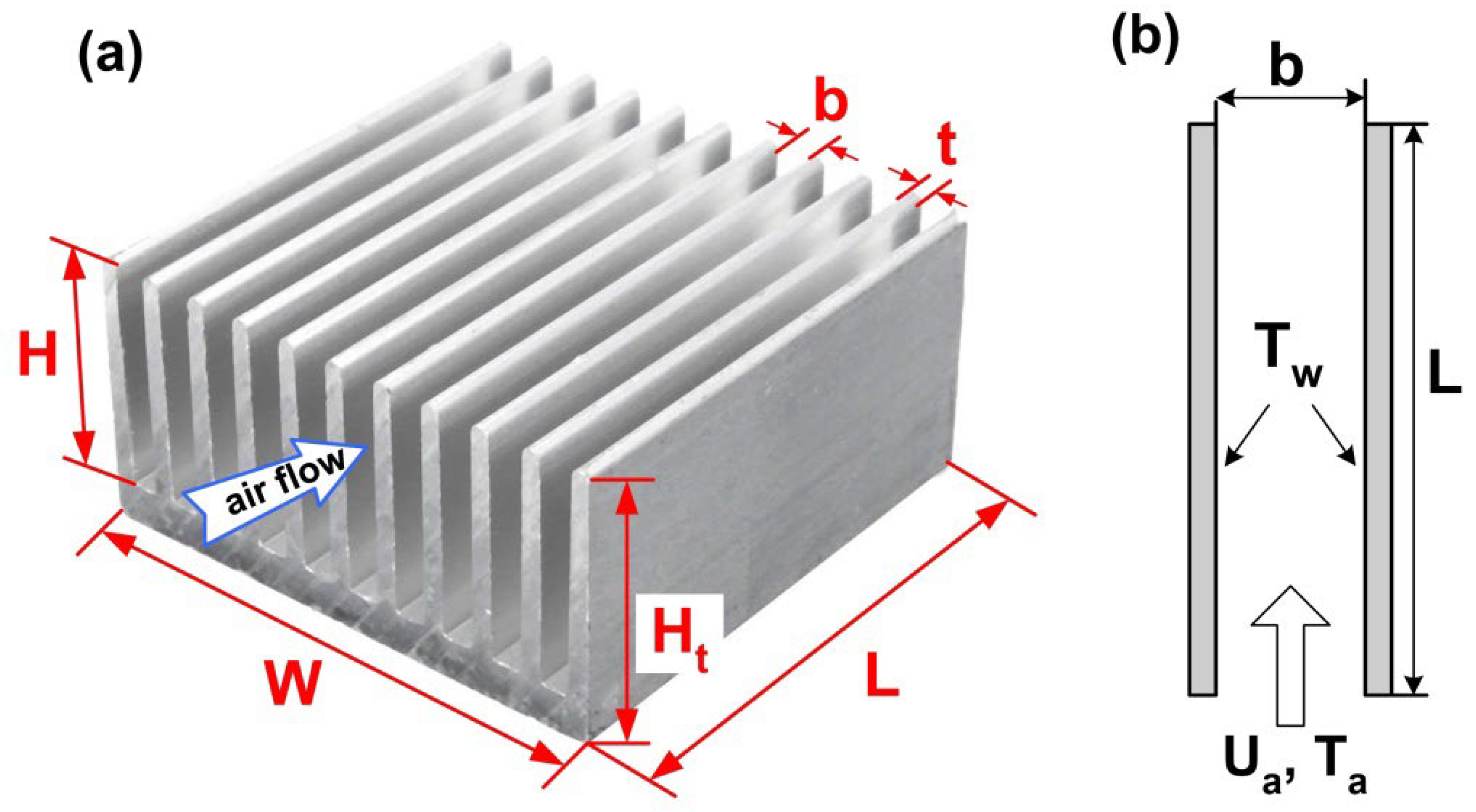
Figure 2.
Schematic diagram of thermal resistance model, along with the main components of the thermoelectric refrigeration system.
Figure 2.
Schematic diagram of thermal resistance model, along with the main components of the thermoelectric refrigeration system.
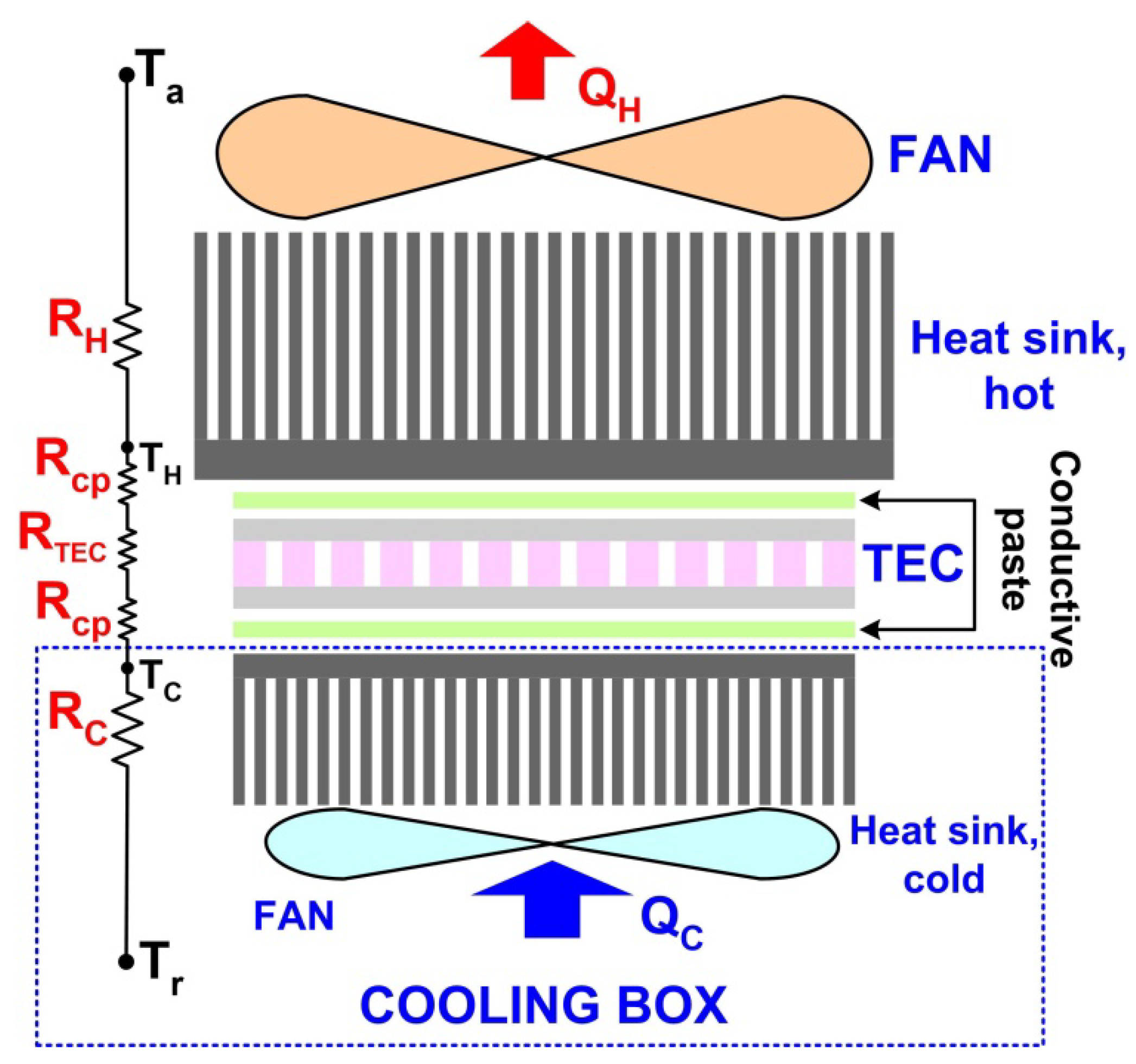
Figure 3.
Schematic description of thermoelectric refrigeration system, tested with different cooling fans and TEC devices.
Figure 3.
Schematic description of thermoelectric refrigeration system, tested with different cooling fans and TEC devices.
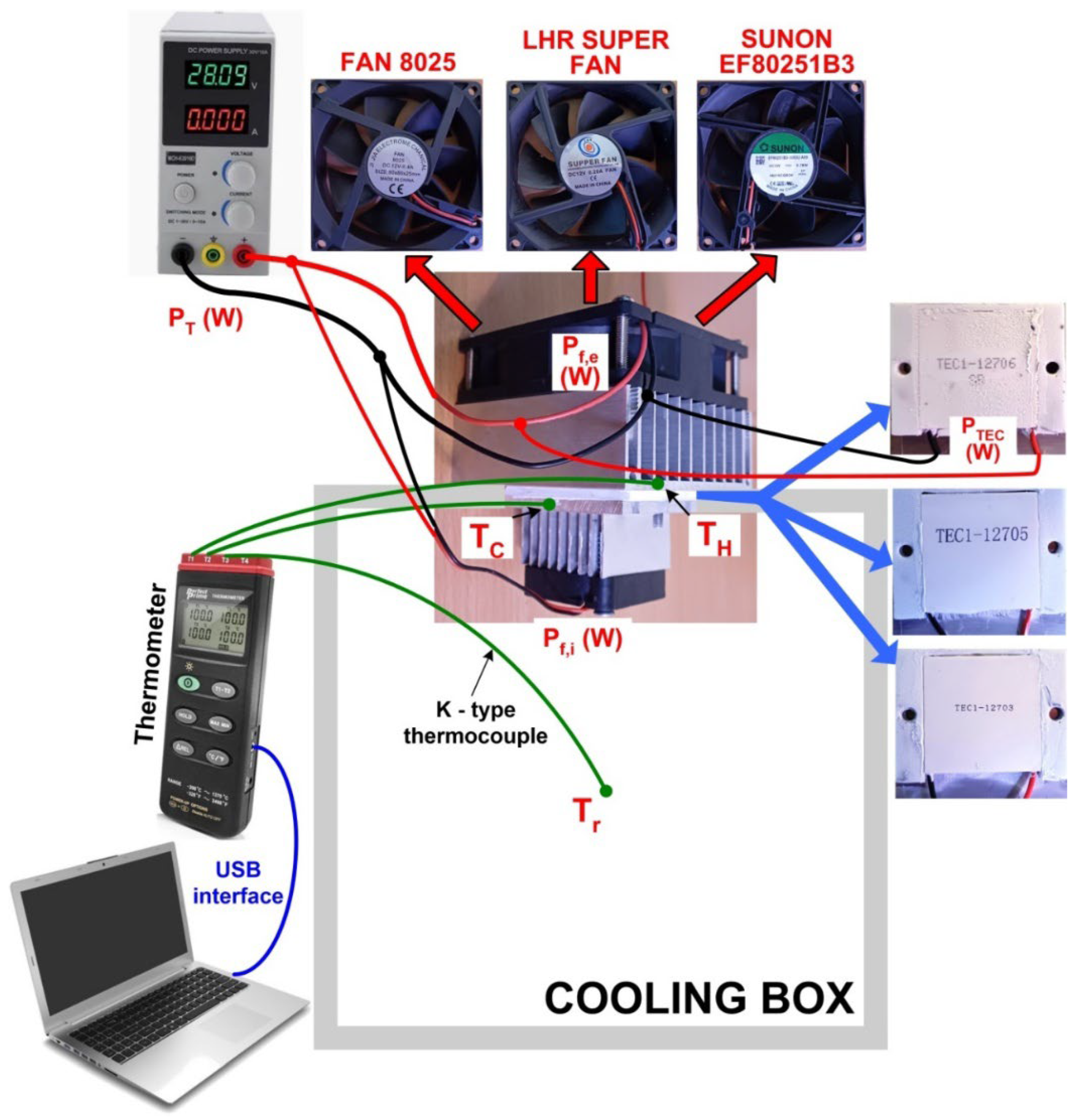
Figure 4.
Experimental rig for the refrigeration system testing with water cooling load.
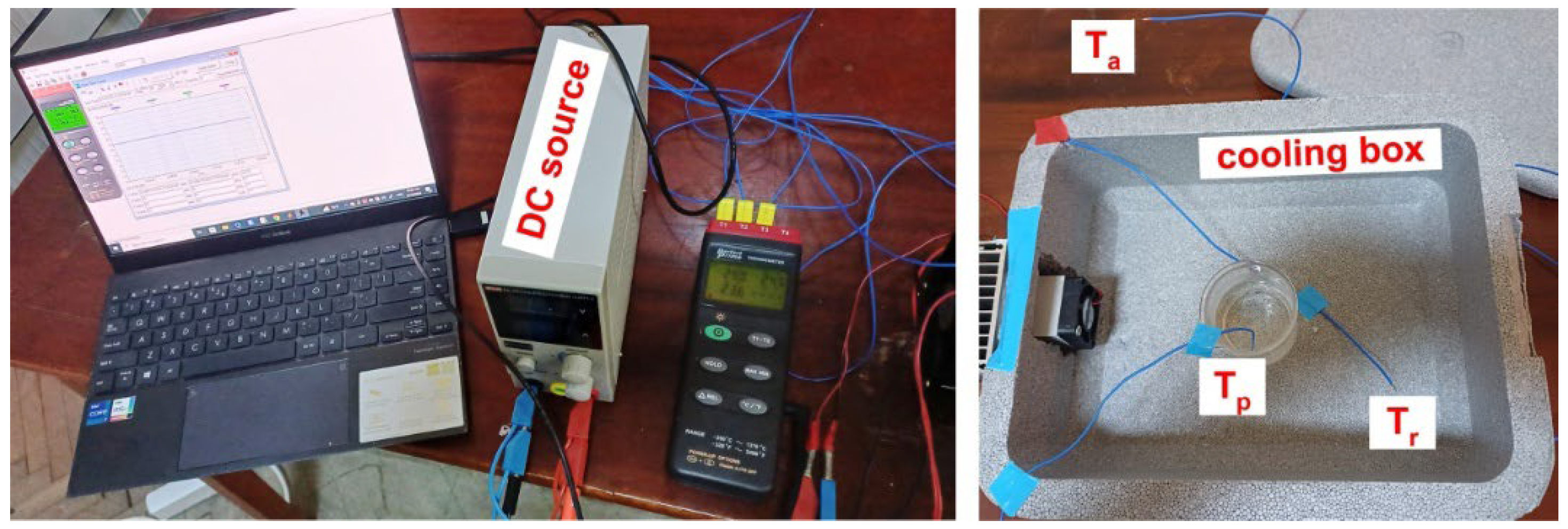
Figure 5.
Variations of the TEC module temperatures and refrigerated air during the cooler testing.
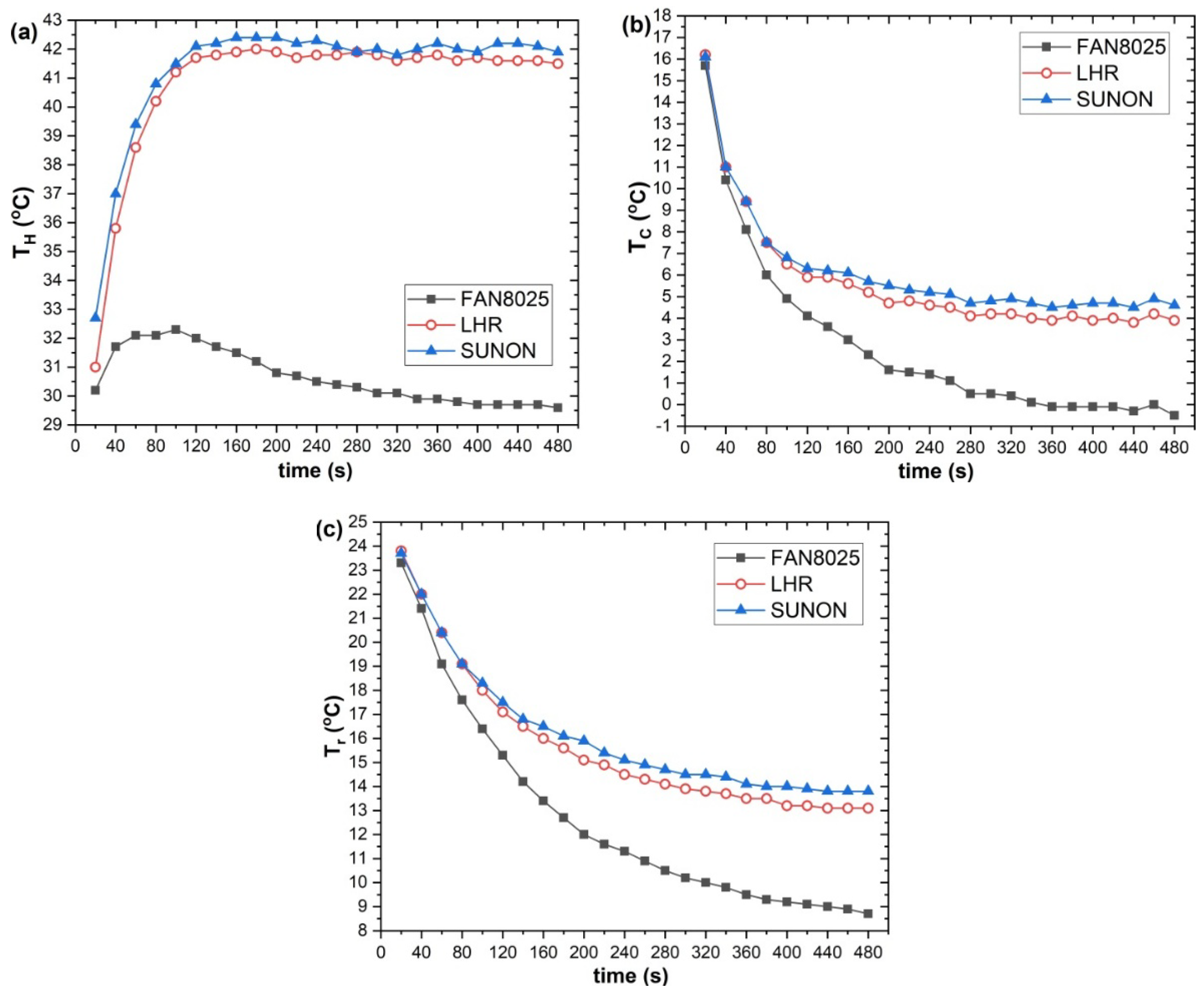
Figure 6.
Evolution of heat dissipation rate for the external heat sink during cooler testing.
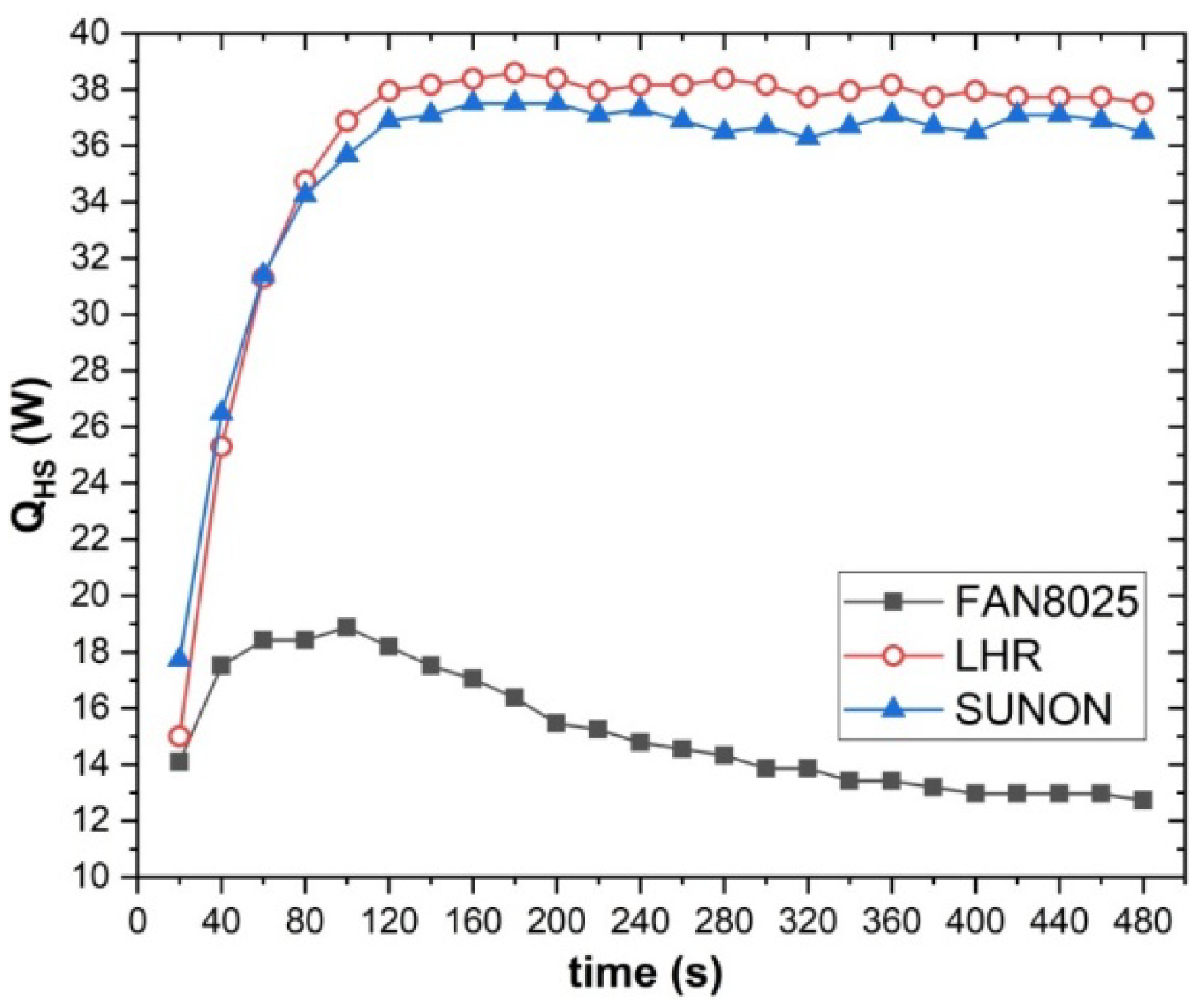
Figure 7.
Evolution of the temperature gradient between the plates of TEC modules.

Figure 8.
Absorbed heat (a), coefficient of performance (b), thermal resistance of the heat sink at the TEC hot side (c) and total thermal resistance of refrigeration system(d) for different TEC modules under cooling test with air load.
Figure 8.
Absorbed heat (a), coefficient of performance (b), thermal resistance of the heat sink at the TEC hot side (c) and total thermal resistance of refrigeration system(d) for different TEC modules under cooling test with air load.
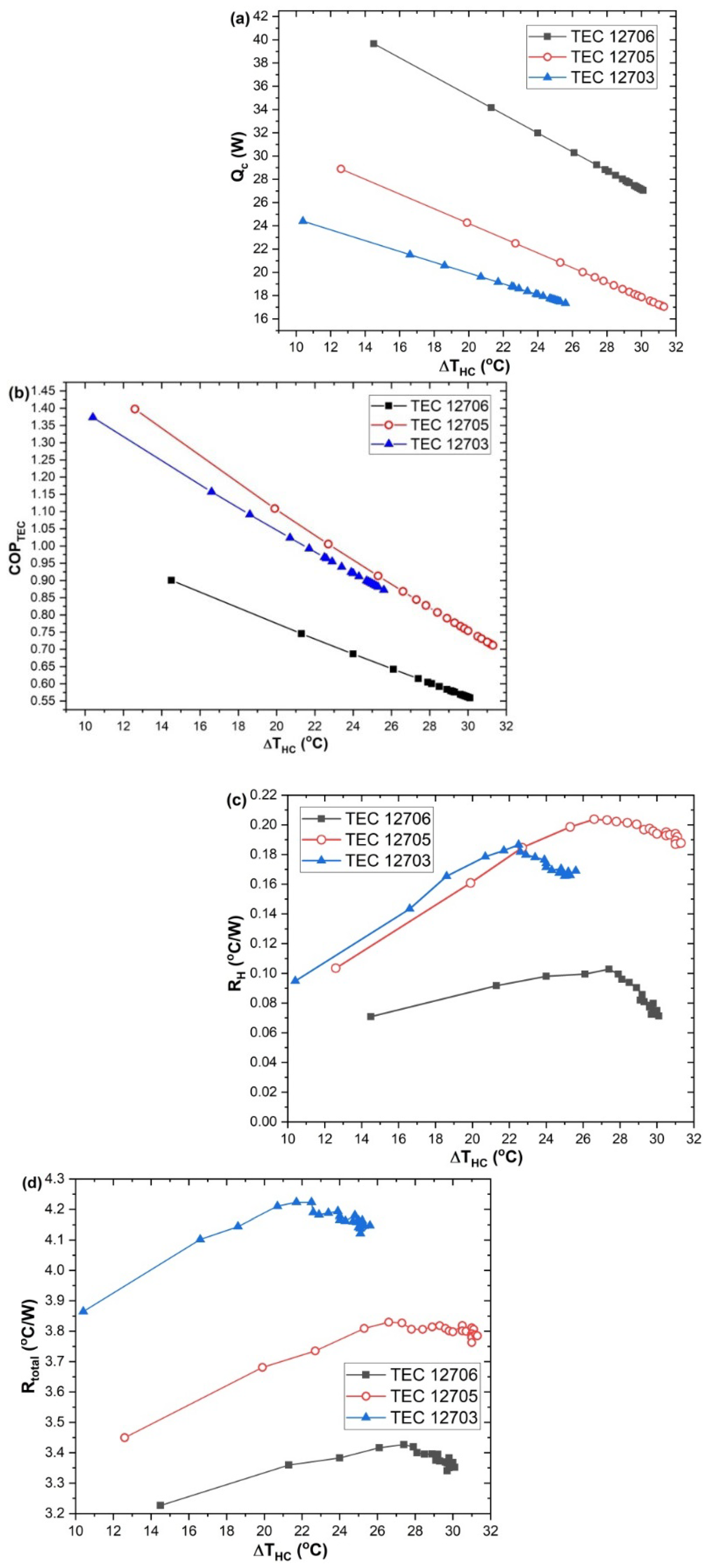
Figure 9.
The evolution with cooling temperature for: (a) irreversibility and (b) exergy efficiency.
Figure 9.
The evolution with cooling temperature for: (a) irreversibility and (b) exergy efficiency.
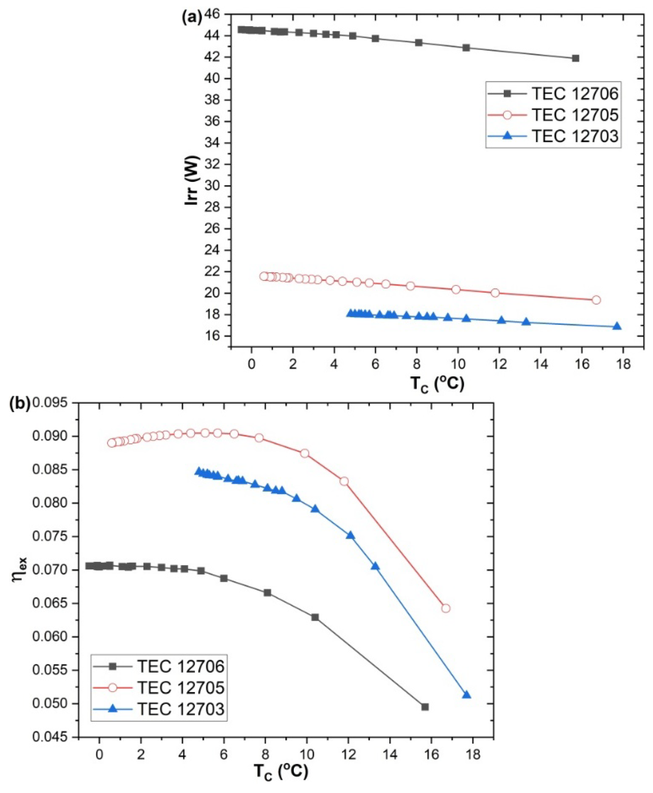
Figure 10.
Variation in temperatures (a) and the coefficient of performance (b) for the refrigeration box with a water cooling load.
Figure 10.
Variation in temperatures (a) and the coefficient of performance (b) for the refrigeration box with a water cooling load.
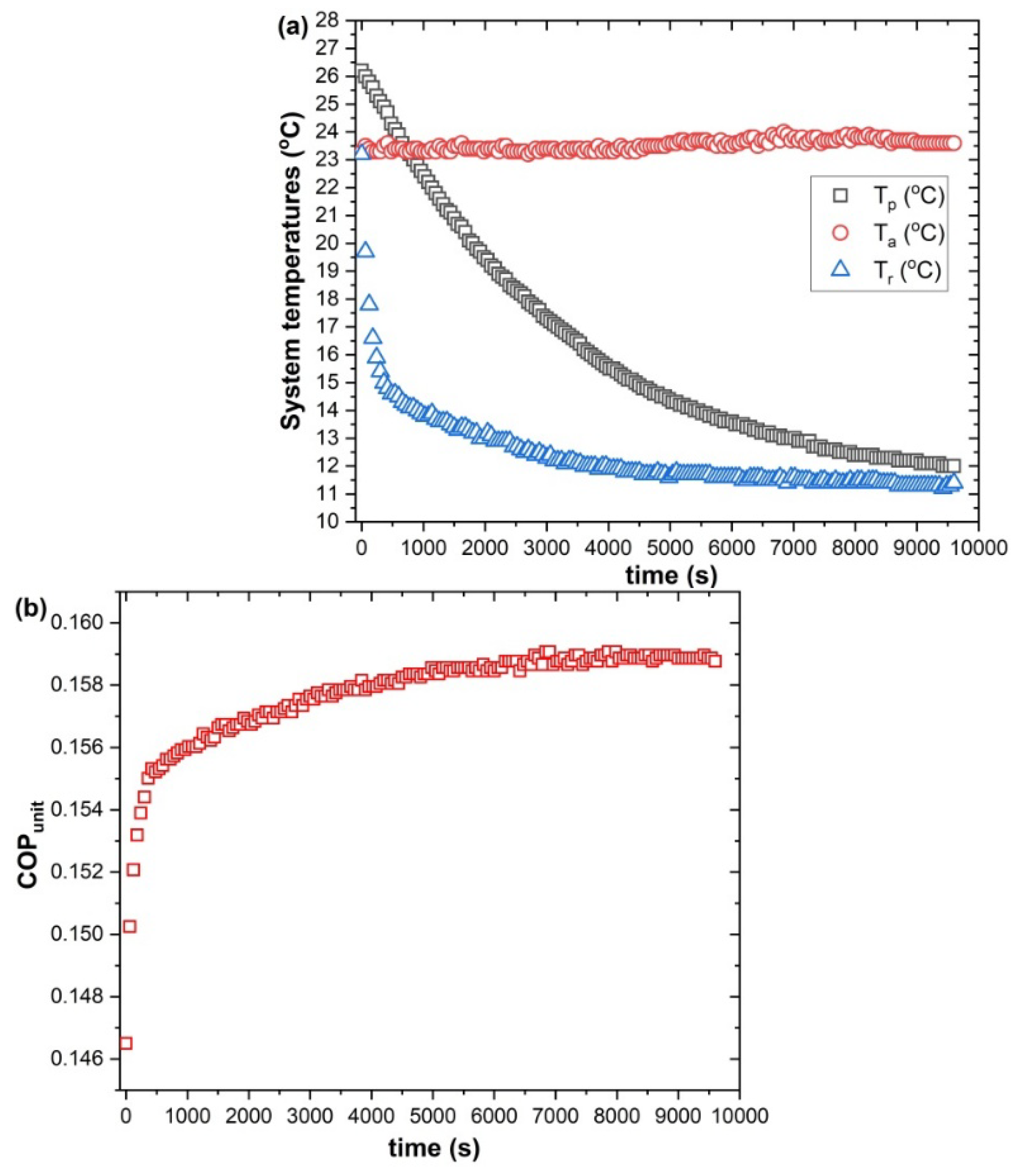
Table 1.
Thermo – physical parameters of TEC devices calculated from performance curves.
| Internal parameters | TEC1-12706 | TEC1-12705 | TEC1-12703 |
|---|---|---|---|
| Sm (V/ K) | 0.056 | 0.0555 | 0.0552 |
| Rm (Ω) | 2.05 | 2.25 | 3 |
| Km (W/K) | 0.562 | 0.511 | 0.372 |
Table 2.
Geometrical parameters of the system heat sinks.
| HS type | N | W (mm) |
L (mm) |
t (mm) |
b (mm) |
Ht (mm) |
H (mm) |
| external | 10 | 68.1 | 80.2 | 1.04 | 6.02 | 27.51 | 25.5 |
| internal | 9 | 39.52 | 39.4 | 0.93 | 4.04 | 26.21 | 21.26 |
Table 4.
Thermal and hydraulic parameters of the heat sink at different convective air tests.
| Cooler type | Reb | Nub | hb (W/m2K) |
|---|---|---|---|
| Fan 8025 | 6905.3 ± 18.7 | 3.74 ± 0.005 | 16.29 ± 0.0008 |
| LHR | 5194.4 ± 33.3 | 3.29 ± 0.01 | 14.54 ± 0.001 |
| SUNON | 4168.9 ± 26.7 | 2.98 ± 0.009 | 13.18 ± 0.007 |
Disclaimer/Publisher’s Note: The statements, opinions and data contained in all publications are solely those of the individual author(s) and contributor(s) and not of MDPI and/or the editor(s). MDPI and/or the editor(s) disclaim responsibility for any injury to people or property resulting from any ideas, methods, instructions or products referred to in the content. |
© 2025 by the authors. Licensee MDPI, Basel, Switzerland. This article is an open access article distributed under the terms and conditions of the Creative Commons Attribution (CC BY) license (http://creativecommons.org/licenses/by/4.0/).
Copyright: This open access article is published under a Creative Commons CC BY 4.0 license, which permit the free download, distribution, and reuse, provided that the author and preprint are cited in any reuse.


