Submitted:
10 June 2025
Posted:
11 June 2025
You are already at the latest version
Abstract
With advancements in radar sensors, communications, and computer technologies, as well as an increasing number of ground observation tasks emerging, Synthetic Aperture Radar (SAR) remote sensing is undergoing a transition from being theory and technology-driven to application-demand driven. Since the late 1960s, Interferometric Synthetic Aperture Radar (InSAR) theories and techniques have continued to develop. They have been significantly applied in various fields such as global topography mapping, ground deformation monitoring, marine observations, and disaster reduction efforts. Recently, space-based InSAR has undergone transformations from single frequency to multi-frequency, from low orbits to high orbits, and from a single platform to multi-platform operations, aiming for high precision and high temporal resolution land observation.
Keywords:
InSAR
; D-InSAR
; single-pass
; repeat-pass
1. Introduction
The interferometric synthetic aperture radar (InSAR) measurement technology, an active quantitative microwave remote sensing technique that has emerged over the past half-century, has been verified as an important technical means for earth observation [1,2,3,4,5,6,7,8,9]. It originated from the "Young's double-slit interference experiment" proposed by Thomas Young in 1801. Principally, it makes use of the amplitude and phase information of SAR images for interference processing and analysis, and plays a decisive role in global topographic mapping, marine hydrological observation, disaster prevention and mitigation, etc., featuring high precision and wide coverage.
Rogers and Ingalls [10] were the first to apply interferometry techniques to terrain observation of Venus and the Moon. In 1974, L.C. Graham [11] proposed the technical principle of using InSAR technology for topographic survey and demonstrated the feasibility of InSAR for topographic survey for the first time, and applied it to X-band airborne radar. Subsequently, the Jet Propulsion Laboratory (JPL) of National Aeronautics and Space Administration (NASA) in the United States conducted the first experimental research on airborne InSAR three-dimensional reconstruction of terrain using airborne side-looking radar, obtaining a digital elevation model (DEM) of San Francisco [12]. In 1988, Goldstein et al. [12] processed SEASAT satellite observation data using InSAR technology, and the topographic maps of Death Valley obtained by them were consistent with the results published by the United States Geological Survey.
With the launch and operation of a large number of SAR satellites, scholars conducted a large number of studies on repeated-pass InSAR technology, effectively promoting the rapid development of related theoretical methods and application technologies. Due to the serious atmospheric delay differences, temporal decorrelation, and low baseline measurement accuracy between multiple passes, repeated-pass InSAR can only be used for surface deformation monitoring and cannot meet the requirements of digital elevation accuracy [13]. To solve the above problems, single-pass interferometric SAR can simultaneously obtain multiple coherent SAR images, such as the earliest Shuttle Radar Topography Mission (SRTM) obtained DEM within the range from 56° south latitude to 60° north latitude that met the Digital Terrain Elevation Data level 2 (DTED-2) standard [14]. The development of InSAR has gone through the process of "ground detection radar - imaging synthetic aperture radar - synthetic aperture radar interferometry", which also indicates that InSAR is the integration of synthetic aperture radar remote sensing imaging and electromagnetic wave interference technologies. The main onboard InSAR systems and technical development history are shown in Figure 1.
This article will elaborate on the development trends of interferometric synthetic aperture radar technology and systems. It mainly starts from repeat-pass interferometry and single-pass interferometry to explore new technologies of synthetic aperture radar interferometric measurement.
2. InSAR Methods
SAR uses range-oriented large-bandwidth pulse compression technology and azimuth-oriented aperture synthesis technology to acquire ground object echoes. After imaging processing, it can realize the observation and characteristic identification of ground image with high resolution. SAR image signal can be expressed as
In the formula: and are the distances from the phase center of the transmitting radar antenna and the receiving radar antenna to the target; is the radar wavelength; is a complex number related to the backscattering of the target and the radar equation. For bistatic radar, . InSAR achieves high-precision relative ranging by interferometric processing of two or more pairs of interferometric SAR images obtained in the same area. Taking two pairs of bistatic SAR images as an example, after interferometric processing, the main and auxiliary SAR images can be expressed as
where: and are the master SAR image and slave SAR image, respectively.
Then the interference phase can be expressed as
where: is the phase Angle operator; and are the oblique distance between the phase center of the master and slave SAR antennas and the target, respectively.
We can see from equation (3)
The accuracy of interferometric phase measurement is related to the phase correlation number γ of master SAR image and slave SAR image. and
where: E (⋅) is the expected function.
The interference phase probability density function of master SAR image and slave SAR image is
where: is multi-look number; Γ (⋅) is the gamma function; f (⋅) is a Gaussian hypergeometric distribution function.
Finally, the interference phase standard difference can be expressed as
3. Status and Application
The technique of interferometric synthetic aperture radar is to find the surface change by comparing two radar images at different time or position. It is mainly divided into repeat-pass interference technology and single-pass interference technology, which is applied to natural disaster monitoring, glacier change, water resources management, land use and change, etc., and also provides data support for the study of climate models, Marine coral reef degradation and other fields.
3.1. Repeat-Pass Interference
Spaceborne SAR system generally uses a single antenna to collect signals. As shown in Figure 2, for a local area, only one SAR image can be obtained by one time satellite flight. Satellite radar repeatedly images the area with a certain time interval and slight orbital deviation, and the SAR images obtained twice can form an interference pair. This configuration is called a single-antenna repeating orbit interference system. After acquiring the initial data of the spaceborne radar system, SAR images can be formed only after computer focusing and filtering [15]. With the in-depth study of InSAR technology, the concept and idea of Differential Interferometric SAR (D-InSAR) were born.
3.1.1. D-InSAR
In 1989, Gabriel et al. [16] first proposed the theory of combining interferometry with differential methods to measure surface deformations, that is, the theory of combining interferometry and differential method to measure surface deformation. They successfully applied this technique to obtain surface deformation data from an irrigation area in California, demonstrating the capability of D-InSAR for high-precision surface deformation monitoring. In 1993, Massonnet and colleagues [17] conducted a study on the Landers earthquake in California, where they used D-InSAR for the first time to extract co-seismic deformation fields, marking the beginning of InSAR's application in the geosciences. Their results were published in Nature, highlighting InSAR's potential and leading to its widespread use in surface deformation monitoring. However, InSAR is highly sensitive to factors such as Atmospheric Phase Screen (APS) and temporal/spatial decorrelation. To address this and enable high-precision, long-term monitoring of surface deformations, researchers began focusing on these challenges after 2001. This led to the development of the various Multi-Temporal InSAR (MT-InSAR) techniques.
The data processing procedure for extracting InSAR deformation information generally includes steps such as registration of primary and secondary SAR images, generation and filtering of interferogram, removal of flat-earth phase, topographic phase removal (i.e., differential processing), phase unwrapping, geometric transformation, and geocoding [18]. The following will focus on the application of D-InSAR in monitoring and analyzing surface deformation caused by seismic activities, volcanic movements, glacier drift, ground subsidence, landslides, etc. For the description and classification of different types of surface deformation, Table 1 presents typical geophysical phenomena and their corresponding surface deformation characteristics. It can be seen that the deformation characteristics presented by different geophysical phenomena are quite different. Before implementing D-InSAR surface deformation detection, investigating and understanding the temporal and spatial characteristics of the monitoring object can guide the selection of appropriate SAR data and setting appropriate processing parameters in the data processing process, and help with the correct interpretation of the deformation field.
In fact, during the SAR interferometric modeling process, the SAR interferometric phase can be regarded as the comprehensive contribution of three factors: the reference ellipsoid, topographic undulation, and surface deformation. On one hand, this is because the low-frequency high-correlation feature of the atmospheric delay phase in spatial distribution can be eliminated by high-pass filtering in a limited research area [4]; while the noise phase can be attributed to systematic errors such as sensor thermal noise, and can be suppressed by low-pass filtering, densified ephemerides, etc. [20]. Therefore, using D-InSAR to measure ground surface deformation is to model the interferometric phase of SAR images and sequentially remove the flat-earth phase and topographic phase. Among them, the flat-earth phase can be calculated and removed based on the SAR satellite orbit parameters and imaging geometric parameters, and the topographic phase can be modeled and removed based on external DEM data or the topographic data generated by another SAR interferometric pair, according to SAR imaging parameters.
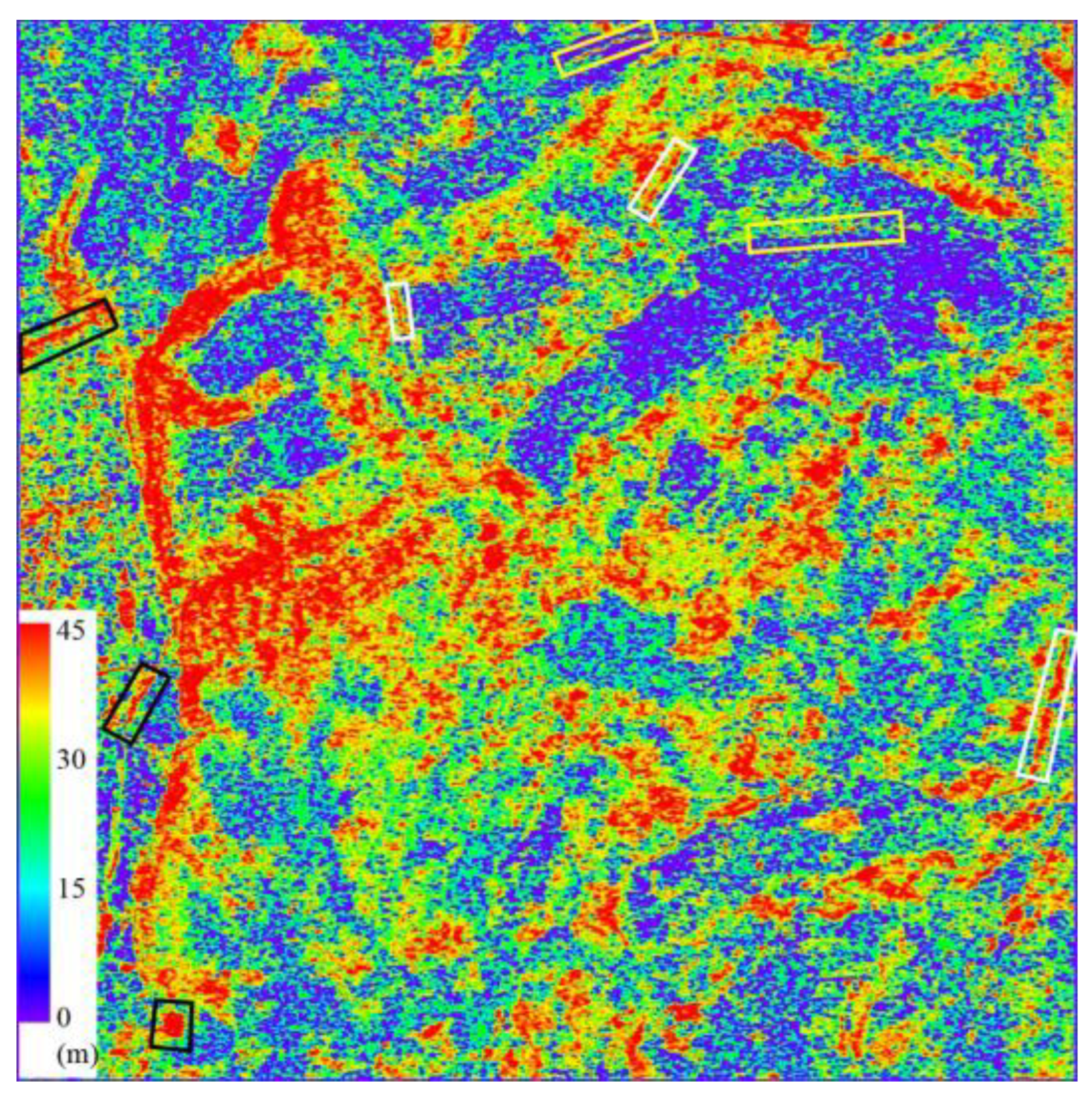
Generating differential interferograms is the primary goal of D-InSAR for monitoring ground surface deformation. Figure 3 shows the basic strategy for generating differential interferograms corresponding to the coseismic deformation field of the 1995 Sakhalin Island earthquake in Russia [4], which is composed of interferograms formed by JERS-1 SAR data. With the phase information of the master SAR image and slave SAR image, and with the assistance of DEM data and orbit data, through differential interferometry processing, differential interferograms reflecting ground surface deformation can be obtained. It can be seen from this that the phase of the differential interferograms shows periodic fringe changes, and each cycle represents a fringe, indicating a phase change of 2π radians, corresponding to half a radar wavelength of deformation.
The size of deformation corresponding to each radian of phase change in the differential interferogram is also called the interferometric sensitivity to displacement of the SAR system. The interferometric sensitivity of the SAR system to deformation is an important indicator for monitoring surface deformation with SAR data. Taking C-band ERS SAR data as an example [21], a deformation of 1 cm along the radar line corresponds to a radar differential interferometric phase change of 2.2 radians (129°); while the same deformation in the L-band PALSAR differential interferogram corresponds to a differential phase change of 0.5 radians (31°) [22]. It can be seen that the D-InSAR interferometric phase is very sensitive to ground surface displacement, and short-wave data is more sensitive than long-wave data. Therefore, if different band SAR data are used to measure the same deformation field, the shorter the radar wavelength, the more fringe periods corresponding to the differential interferogram. Similarly, in the same differential interferogram, the place with a larger deformation gradient corresponds to a denser deformation phase fringe. From the above analysis, by observing the density of phase fringes in the differential interferogram, the concentrated range and intensity of ground surface deformation can be evaluated. Figure 4 shows the differential interferogram of the Izmit earthquake, and the red line segment indicates the location of the fault rupture. It can be seen that the differential interferogram fringes run through the entire interferogram, and deformation occurred within 100 km around the fault rupture due to the earthquake. Moreover, the fringes near the fault are relatively dense, while the ground surface deformation fringes far from the fault are relatively sparse, which is caused by the larger deformation gradient near the fault compared to the far-field region. According to the rule that the surface deformation of 2.8 cm in the line of sight corresponds to a striped pattern cycle, the number of fringes in the deformation field can be observed to estimate the deformation amount in the epicentral area (as shown by the white lines). However, due to the excessive density of fringes in the epicentral area, it is difficult to accurately estimate the ground surface deformation amount in these areas using visual interpretation methods. In the D-InSAR data processing, the phase unwrapping technology is adopted to restore the absolute phase, thereby accurately measuring the ground surface deformation in the epicentral area.
The most common application of D-InSAR deformation monitoring is the measurement of coseismic deformation fields of earthquakes [24]. Since the 1990s, many research institutions have begun to use InSAR to measure the coseismic deformation fields of earthquakes that have occurred worldwide and have carried out inversion work on the sliding fault models [25,26,27]. Figure 5 shows the mosaic map of the coseismic deformation fields of the four 7.7-8.4 magnitude earthquakes that occurred in Chile from 1992 to 2000 calculated from the ERS-1/2 SAR images [28], and Figure 6 shows the coseismic deformation fields and the inversion results of the sliding fault of the 6.8 magnitude earthquake in Bam, Iran in 2003 calculated from the ENVISAT ASAR images [29]. A large number of studies have shown that the application of InSAR in the monitoring and analysis of coseismic deformation fields of earthquakes has obvious technical advantages such as high deformation measurement accuracy and wide coverage. This high-density surface deformation data provides unique key basic data for earthquake mechanism research and model inversion.
It is worth noting that some scholars are exploring the joint monitoring of coseismic deformation before and after earthquakes by combining geodetic techniques such as global navigation satellite system (GNSS) with InSAR technology, attempting to understand the earthquake mechanism more deeply and making new attempts for crustal deformation monitoring and even earthquake prediction [27,30,31]. Compared with conventional geodetic deformation monitoring techniques such as precision level measurement and GNSS, InSAR has the characteristics of high accuracy, high resolution, wide coverage, low cost, safety, and continuous observation. It has incomparable superiority to conventional deformation monitoring methods [18,32]. Table 2 lists the comparison between InSAR and precision level measurement and GNSS technologies. Compared with geodetic technologies based on point observations, InSAR is a unique space geodetic measurement technology based on surface observations, which can supplement the existing low spatial resolution geodetic measurement technologies such as precise leveling measurement and GNSS. Therefore, InSAR provides an economic and effective space earth observation approach for geophysical research and deformation disaster monitoring.
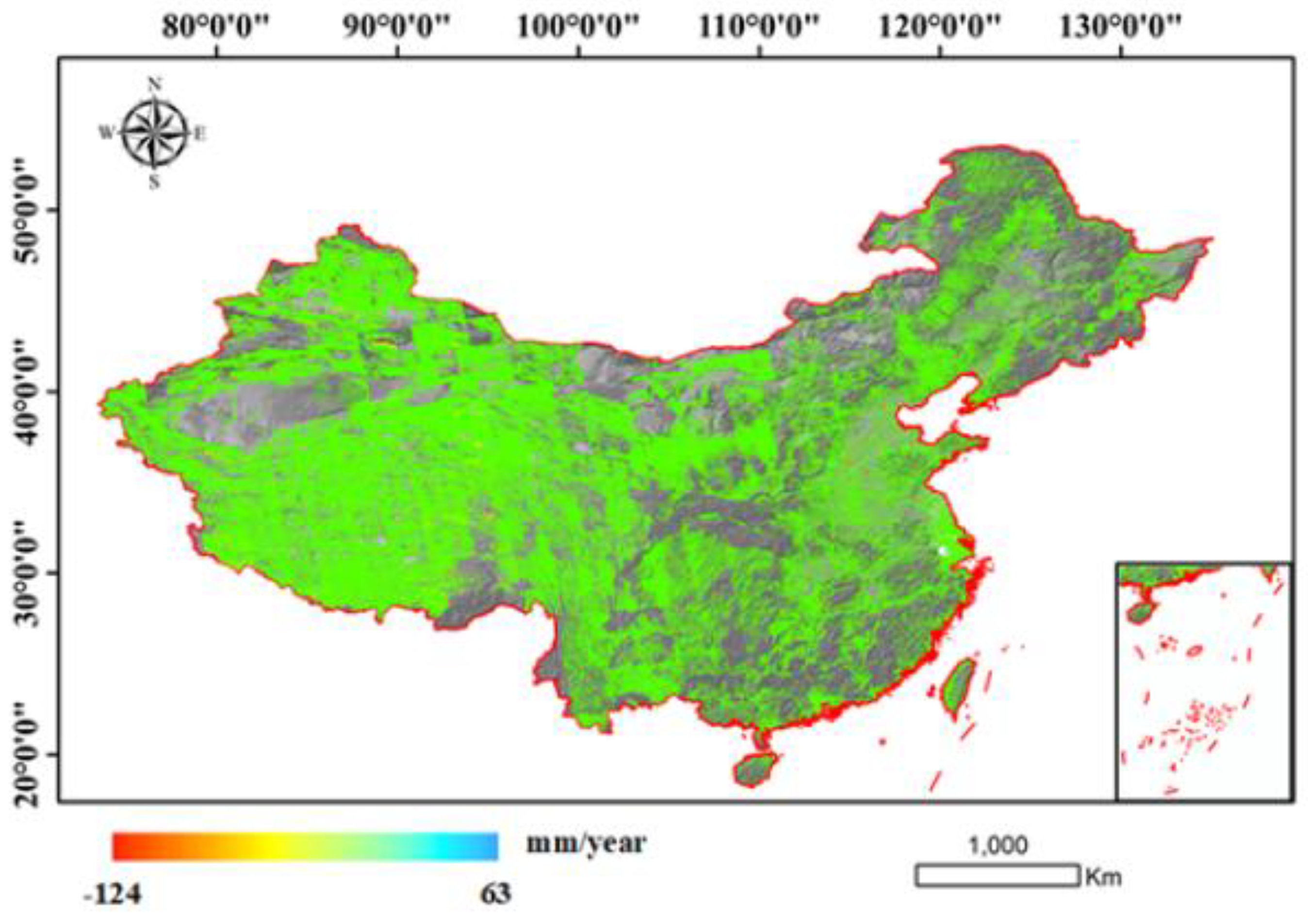
In May 2022, Wuhan University released "a map of ground surface deformation across the country with a resolution of 40 meters and an accuracy of 5 mm/year" [33], which was produced using Sentinel-1A/B time-series InSAR data covering China in 2021. This achievement was verified by Qianxun Position Network Co., Ltd. through the distribution of more than 2,000 base stations of the Beidou ground-based augmentation system in the terrestrial area. The accuracy of the ground surface deformation rate in the Chinese region was 4.82 mm/year. In December 2020, the Aerospace Information Research Institute of the Chinese Academy of Sciences released a national ground subsidy monitoring map based on a supercomputing InSAR system [34,35]. This map is the world's first of its kind, with extensive coverage and a large amount of processed data. In 2022, Li et al. [36] used InSAR time-series technology to systematically detect earthquake-accelerated landslides triggered by the 2016-2017 Central Italy earthquake sequence. This marked the first large-scale detection of earthquake-accelerated landslides, revealing their long-term response to seismic effects.
Figure 7.
InSAR National Deformation Map by Wuhan University[33].
Figure 7.
InSAR National Deformation Map by Wuhan University[33].
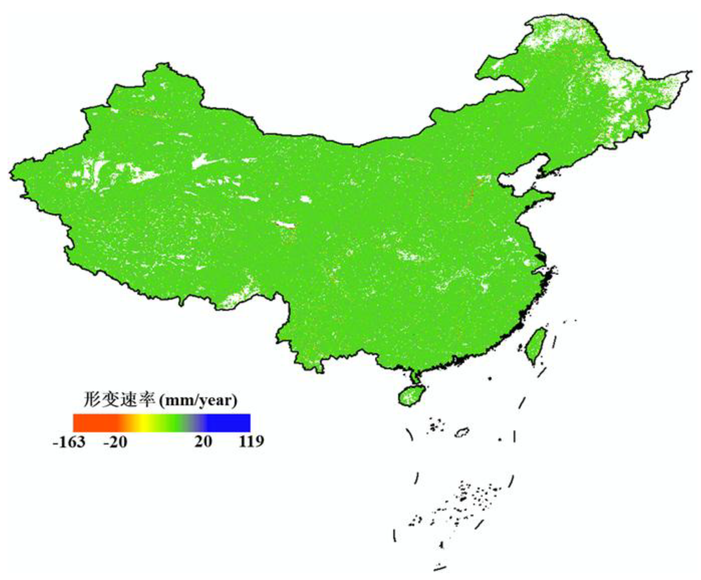
Figure 8.
InSAR National Deformation Map by AIR-CAS [34].
Figure 8.
InSAR National Deformation Map by AIR-CAS [34].
3.1.2. PS-InSAR
In 2001, Ferretti et al. [37] introduced the Permanent Scatterers InSAR (PS-InSAR) technique. Through statistical analysis of time-series SAR data of the same area, high-coherence points (i.e., PS points) were detected. By modeling and analyzing discrete PS points, the influence of atmospheric delay could be weakened, and surface deformation and elevation information could be accurately separated. This technique extracts stable and high-Signal-to-Noise Ratio (SNR) features to eliminate noise and other interferences in the interference map. This method enabled the creation of sub-meter precision surface elevation models and millimeter-level surface deformation monitoring. It has proven especially effective for monitoring infrastructure such as buildings, roads, and dams, often achieving observation precision of 1 millimeter or even better [38].
Ferretti et al. [37,39] successively proposed three methods for identifying permanent scatterers, namely the coherence coefficient threshold method, the amplitude deviation index threshold method, and the phase deviation threshold method. Adam et al. [40] proposed the method using Signal-to-Clutter Ratio (SCR). Hooper et al. [41] proposed the StaMPS method, which selects permanent scatterers by using the maximum likelihood method and compares the results with those of traditional InSAR processing as shown in Figure 9. Ferretti et al. [42] proposed the SqueeSAR method, which combines PS points and Distributed Scatterers (DS) and solves the problem by using the PS-InSAR processing flow, thereby improving the point density of deformation monitoring and expanding the application field of PS-InSAR technology. These methods are based on large data volumes and select permanent scatterers from a statistical perspective, which are not suitable for data processing with small datasets. Therefore, they limit the application of time series radar interferometry [43,44,45].
3.1.3. SBAS-InSAR
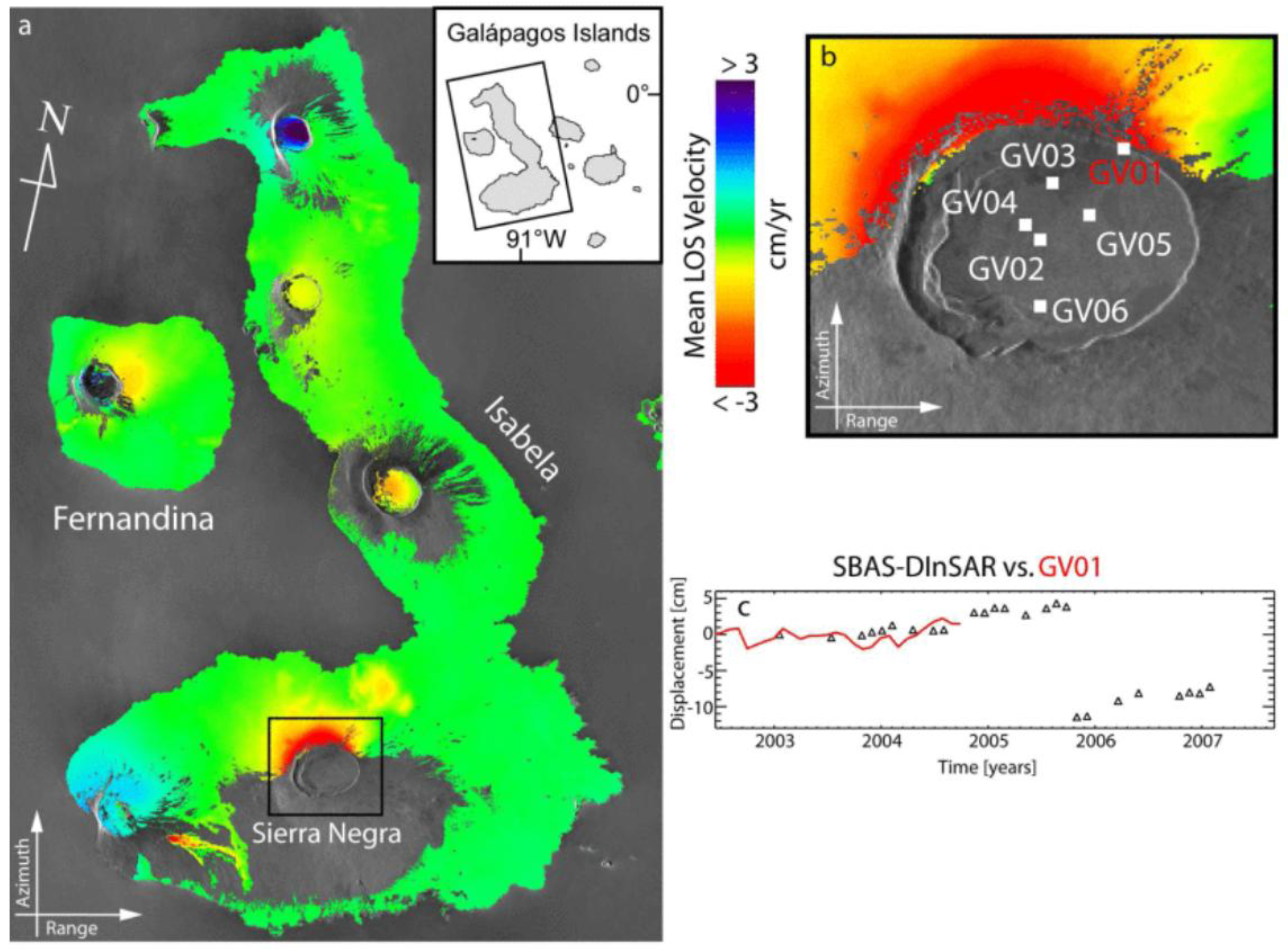
In 2002, Berardino et al. [46] proposed the Small Baseline Subset (SBAS) method. By selecting short time-space baseline interferograms, the SBAS method limited the decoherence problem caused by long time-space baselines [47]. Compared with PS-InSAR technology, the SBAS method selects more interferograms for calculation. Based on the interferogram phase of the high coherence points in the time series, a deformation model is established. Due to the existence of correlated observations in the interferogram phase, the Singular Value Decomposition (SVD) method is adopted to solve the deformation information and elevation correction amount. This method requires multi-view processing of SAR data, so it is mostly used in large-scale surface subsidence surveys[49–55].
Figure 10.
SBAS- InSAR results. (a) Mean deformation velocity map. (b) Zoom of Sierra Negra caldera. The white marks indicate the locations of the stations in the continuous GPS network that has been deployed since 2002. (c) Comparison between the SBAS-InSAR time-series (black triangles) and the LOS projected GPS measurements (red line) in correspondence to the GPS station labeled as GV01 [its location is shown in (b)] [48].
3.2. Single-Pass Interference
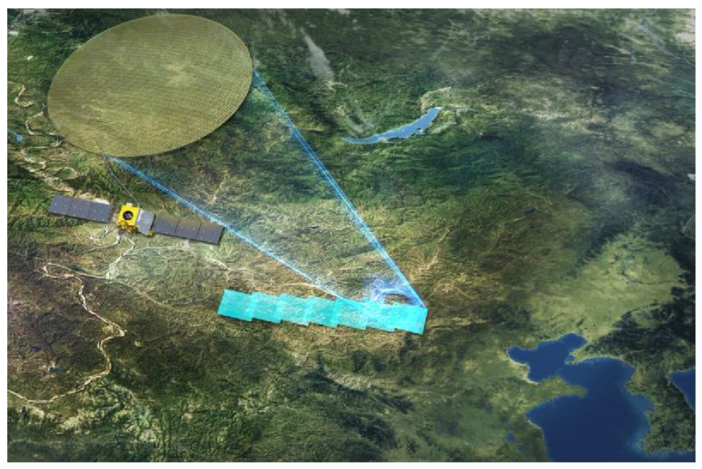
The single-pass mode enables simultaneous acquisition of dual-channel SAR data in a single flight by installing two antennas on the same platform. It has the advantages of being unaffected by time decoherence, having less atmospheric interference, and stable baseline. The single-pass mode can be further classified into Cross Track Interferometry (XTI) and Along Track Interferometry (ATI) based on the different baseline structures. XTI refers to the working mode where the baseline is perpendicular to the heading direction, as shown in Figure 11 (left), and in this mode, one antenna transmits electromagnetic waves while the other two antennas simultaneously receive the reflected information from the ground. The interference phase is caused by the path difference between the two antennas and the ground target, and this path difference has a geometric relationship with the terrain. Therefore, this mode is used to obtain elevation information of the ground surface. ATI mode refers to the working mode where the baseline is parallel to the heading direction, as shown in Figure 11 (right), and the interference phase is mainly caused by the displacement changes of the ground target within two observations. Thus, this mode is often used for detecting ground target movement, mapping of water flow, etc. It is difficult to build two SAR systems with a certain baseline distance on the spacecraft platform, so this mode is mainly used on airborne platforms.
3.2.1. CT-InSAR
Compared with optical satellites, InSAR systems basically do not have limitations on imaging ground targets due to conditions such as day and night, and weather. Especially in areas with perennial rain, uninhabited areas and foreign regions, InSAR systems have unparalleled advantages. Compared with SAR stereo mapping technology, the InSAR technology with phase measurement has higher measurement accuracy. Table 3 lists the comparison between InSAR and other DEM acquisition technologies. Currently, terrain measurement using InSAR technology can already achieve operational application. For example, SRTM system, TanDEM-X system and the mapping project for the blank areas of 1:50,000 topographic maps in western China, etc.
Since interferometric measurement requires two SAR images with high coherence in the same region, and the interferometric phase cannot be directly obtained from the complex images, the generation of DSM requires several steps such as complex image registration, interferogram generation, interferometric phase filtering, phase unwrapping, baseline estimation and DSM reconstruction. The specific processing flow is shown in Figure 12.
In 2000, the SRTM system of the United States [56,57] acquired SAR data ranging from 60°N to 56°S. This system extended a 60m telescopic boom to project an X-band and a C-band antenna outside the cabin, forming a dual-antenna InSAR system with the main antenna inside the cabin. Using InSAR technology, it produced DEM products covering 80% of the global land surface. The product had a planar resolution of 30m×30m, a relative elevation accuracy of 6m, and an absolute elevation accuracy of 16m, meeting the DTED-2 standard in Table 4.
In 2010, the German satellite TanDEM-X was successfully launched and operated in a HELIX configuration with the previous TerraSAR-X satellite [58–60], pioneering true spaceborne dual-station SAR interferometric measurement. Compared with SRTM data, the TanDEM-X DEM expanded from 60°N to 56°S to cover the entire globe, including all regions of the North and South Poles, and the spatial resolution and elevation accuracy increased to 12m and 2m respectively, meeting the HRTI-3 standard in Table 4.
The TianHui-2 dual-satellite formation launched in 2019 [61,62] has a payload of high-resolution synthetic aperture radar and high-precision inter-satellite relative state measurement equipment, etc. It acquires global radar images and auxiliary measurement data in all-weather and all-time conditions, and quickly and efficiently produces digital surface models (DSM).
The PIESAT-1(01) satellites launched in 2022 was developed by Galaxy Aerospace. This satellite system adopts the world's first "1+3" wheel formation multi-satellite distributed interferometric configuration, consisting of 4 high-resolution X-band radar satellites, and has the capabilities of high-precision terrain mapping, high-resolution wide-angle imaging, and high-precision deformation monitoring, etc. It can quickly and efficiently produce high-precision digital surface models (DSM) and complete global non-polar region mapping tasks, and is widely applied in domestic emergency disaster reduction, ecological environment, natural resources and other scenarios. Through the elevation accuracy verification of the RAW DSM products in Yuyang County, Hunan Province using the ICESAT2 laser control point data, the absolute elevation mean error is 3.34m, meeting the terrain mapping accuracy requirements of 1:50,000 scale in hilly areas. The RAW DSM products in Yuyang County, Hunan Province are shown in Figure 13.
3.2.2. AT-InSAR
The Along-Track Interferometry method involves placing two antenna pairs along the flight path to image the same scene. Each antenna processes its own image. Due to the movement of the ocean surface, there will be a phase difference between the two images. This phase difference can be used to measure the line-of-sight velocity of ocean surface currents, as shown in Figure 11 (right). In 2000, Romeiser discussed the feasibility and limitations of ATI flow measurement through model simulation [64], and in 2010, he applied AT-InSAR to TerraSAR-X. The data processing results verified the effectiveness of the in-track interferometry method in flow field measurement and inversion [65].
In February 2000, the SRTM, which was mainly used for precise mapping of global terrain. The aircraft placed the main antenna inside the cabin and the secondary antenna outside, forming a 60-meter long cross-track interferometry baseline and a 7-meter long in-track interferometry baseline [56]. Romeiser and Thompson conducted numerical simulation studies on the imaging mechanism of AT-InSAR for ocean surface currents, proving the feasibility and limitations of AT-InSAR in measuring the radial velocity of ocean surface currents, that is, the along-track interferometry phase is not simply proportional to the radial velocity of ocean surface currents in the line-of-sight direction. It also includes phase deviations caused by Bragg waves, ocean waves, and sea surface wind fields [64]. Romeiser also proposed a composite ocean surface model for calculating the normalized radar backscattering cross section (NRCS) of the ocean surface under medium incidence angles. This model incorporates the analysis of sea surface wind fields and Bragg waves [66,67].
Based on this, Romeiser et al. demonstrated the feasibility of airborne AT-InSAR for measuring ocean surface currents using SRTM interferometric data from the Waddenzee region in the Netherlands and KUSTWAD flow field data [68], and used SRTM interferometric data from the Orkney Islands in northern Scotland to again prove the application prospects of airborne AT-InSAR, launching the DLR's AT-InSAR mission (TerraSAR-X) [69]. They comprehensively discussed the theoretical ocean surface current measurement capabilities of TerraSAR-X AT-InSAR mode, and the results proved that the ocean surface current measurement capability of TerraSAR-X AT-InSAR mode was at least comparable to that of SRTM [70].
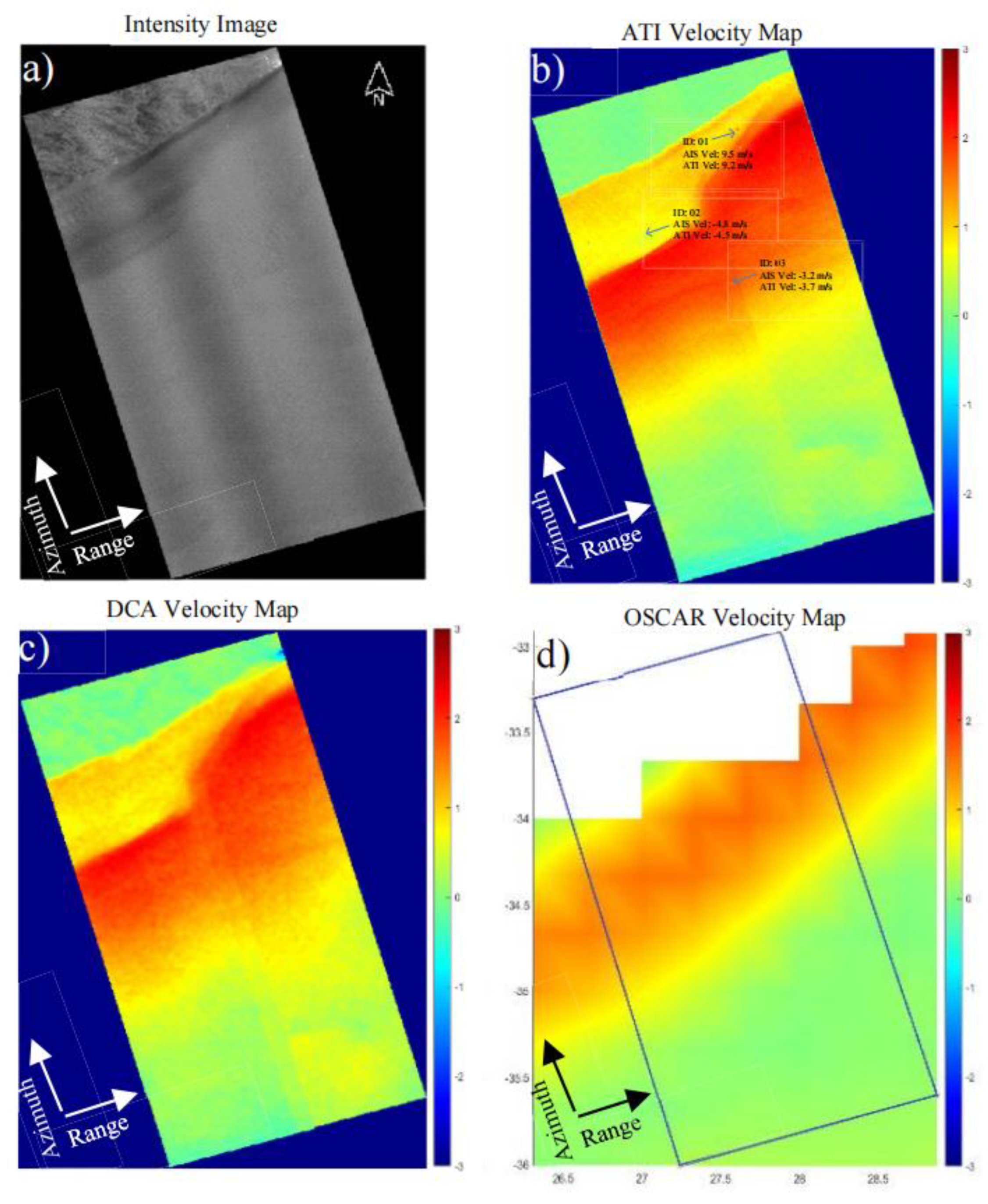
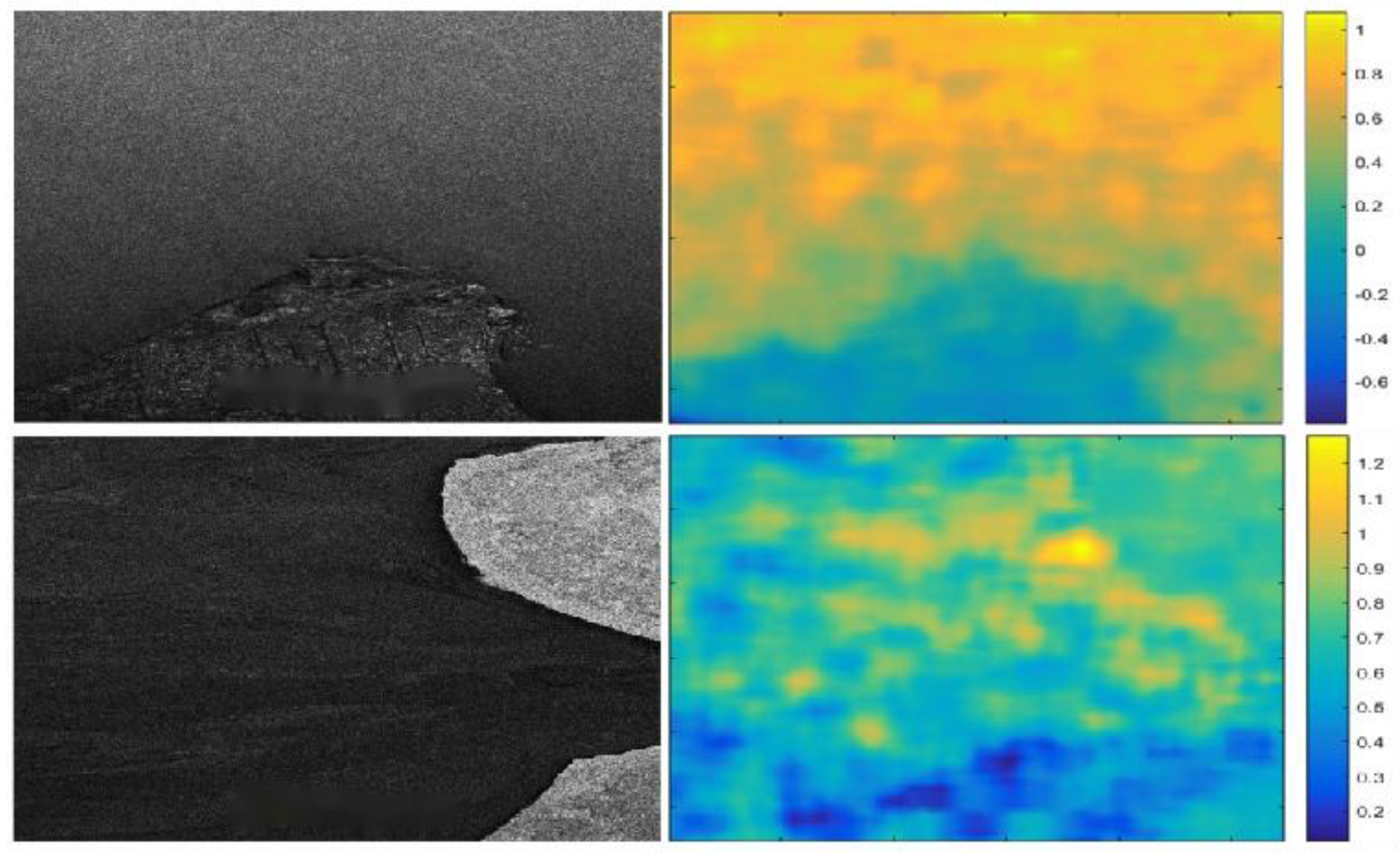
At the European Conference on Synthetic Aperture Radar (EUSAR) in 2022, Ahmed et al. presented an analysis report on the Radarsat-2's MODEX-1 ATI mode and Doppler centroid anomaly (DCA) for estimating the radial velocity of ocean surface currents. The paper processed the Agulhas Current data obtained by Radarsat-2 MODEX-1 in 2021, and the processing results are shown in the following figure. Under the condition of approximately equal accuracy, the spatial resolution of ATI is ten times higher than that of DCA [71].
Figure 14.
ATI and DCA products example from the joint processing chain; Agulhas Current site, on 06 March 2021[71].
Figure 14.
ATI and DCA products example from the joint processing chain; Agulhas Current site, on 06 March 2021[71].
In August 2016, China launched GF-3 satellite, a C-band multi-polarization synthetic aperture radar imaging satellite with a resolution of 1 meter [72–74]. The satellite was equipped with a 15m×1.232m four-polarization waveguide slot phased array SAR antenna [75]. The antenna array surface was divided into 4 deployable panels, each panel contained 6 identical modules, and each module contained 16 unit dual-polarization waveguide slot subarrays, supporting the single antenna dual-aperture ATI experimental mode [76]. In 2019, Yuan Xinzhe et al. conducted the first experiment of measuring ocean surface currents using the ATI mode of GF-3 satellite in Jiaozhou Bay, China. The full-aperture transmitting radar signal was emitted, and the echoes were received simultaneously by two sub-apertures divided in half along the orbit. The effective baseline of the interferometric measurement was 3.75m. The ECMWF (European Centre for Medium Weather Forecasts) wind field was used as the on-site wind speed, and the root mean square error between the HFSWR (High Frequency Surface Wave Radar) data and the measured values was less than 0.2m/s [77].
Figure 15.
The measurement results of ocean surface currents by the ATI mode of GF-3 satellite.
To obtain the two-dimensional ocean surface current, two sets of mutually perpendicular radial velocity components of the ocean surface flow need to be simultaneously acquired. In 1994, Rodriguez et al. [78] first mentioned the extended method of ATI-SAR for estimating ocean surface flow, and in 2001, Frasier and Camp named it dual-beam interferometer (DBI), which can achieve the acquisition of two-dimensional ocean surface current with a single pass [79].
The observation geometry of the DBI method is shown in the following figure. In the coherent radar, a pair of dual-beam antennas are adopted, and each antenna generates a forward and a backward beam. Due to the forward motion of the flight platform, the echo frequency of the forward beam increases, and the echo frequency of the backward beam decreases. The time required for the spatially registered backward antenna echo and forward antenna echo to move between each other is determined according to the traverse antenna baseline distance B. The radar echoes from the two forward beams and the radar echoes from the two backward beams are cross-correlated, generating a pair of interferograms. The phase of each interferogram provides a line-of-sight component of the Doppler surface velocity, and then the vector estimation is obtained by appropriately combining the separated interferograms.
As shown in the right part of Figure 16, the radial velocity measurement of the target point in the forward beam is as follows
Then
Then the phase at the point is
Herein, represents the wave number, represents the coherence time, and . From this, the radial velocity measurement formula can be derived. represents the estimated value of radial velocity. According to the geometric relationship, the radial velocities measured by the forward and backward beams can be used to calculate the two-dimensional ocean surface currents, which are the velocity components of the ocean surface currents along the track and perpendicular to the track respectively:
Among them, is called the projection squint angle. The variance of radial velocity can be obtained by measuring the radial velocity from the forward and backward wave beams:
The derivation of the phase yields the overall variance of the velocity as follows:
At the International Geoscience and Remote Sensing Symposium (IGARSS) in 2011, Christopher Buck introduced the Wavemill project. In November 2011, an airborne test was conducted to verify the feasibility of the squint InSAR method. A software for squint InSAR processing was developed, and the situation of squint InSAR products was evaluated. Further potential was explored to optimize the system design [80]. Regarding the airborne test of the Wavemill project, Yague-Martinez et al. [81] presented the system parameters and processing algorithms of the airborne test at the EUSAR conference in 2012. The airborne test area was in Liverpool Bay and Anglesey, UK.
The formation along track interference has the characteristics of flexible multi-baseline, mixed baseline and multi-angle observation. It can measure ocean surface currents, sea surface wind fields, and ocean waves while also conducting elevation mapping of the sea surface.
In June 2010, TanDEM-X (TDX) was launched into space. Together with TerraSAR-X (TSX) which was launched earlier, they formed a dual-star formation in Helix configuration. The main task of the TSX and TDX radar system formation was to map the global DEM. The working distance could be controlled within 150 to 400 meters [58,59,82,83]. Besides, the TSX and TDX radar system formation could provide baseline along the flight path within zero to a few kilometers range because TDX also had dual-reception mode. After forming a dual-star formation with TSX, it could be equivalent to having four phase centers along the flight path for interferometric SAR with long and short baselines. As shown in Figure 17, the design of long and short baselines can effectively solve the phase ambiguity problem of high-speed scatterers [13]. The long baseline is sensitive to slow motion while the short baseline is sensitive to fast motion.
In early 2012, Romeiser et al. [84,85] first obtained two sets of data with nearly optimal baselines from the TDX satellite formation. The imaging area was in the northern part of Scotland and the Orkney Islands to its north. Besides the along-track interferometric data from the TDX satellite formation, Aperture Switching (AS) mode data from TSX satellite was acquired in this area in 2009, and DRA mode data from TSX satellite was acquired in this area in 2010. By comparing the processing results of TSX satellite DRA mode data processed by DCA and TDX satellite formation data processed by ATI, it was found that the DRA mode must be averaged within a resolution of 1000m×1000m to achieve an error of 0.1m/s, while in the ATI mode, an error of 0.1m/s can reach a resolution of 33m×33m. The results show that the accuracy of the ocean surface flow of DCA is lower than that of the ATI method, approaching the accuracy of the short-baseline ATI method. DCA is an effective alternative method to the single-star dual-channel receiving antenna mode ATI. The ATI processing results of TDX satellite formation prove the true potential of ATI technology when approaching the optimal baseline [86].
4. Trends and Prospects
4.1. Multidimensional
4.1.1. Multi-Star Networking
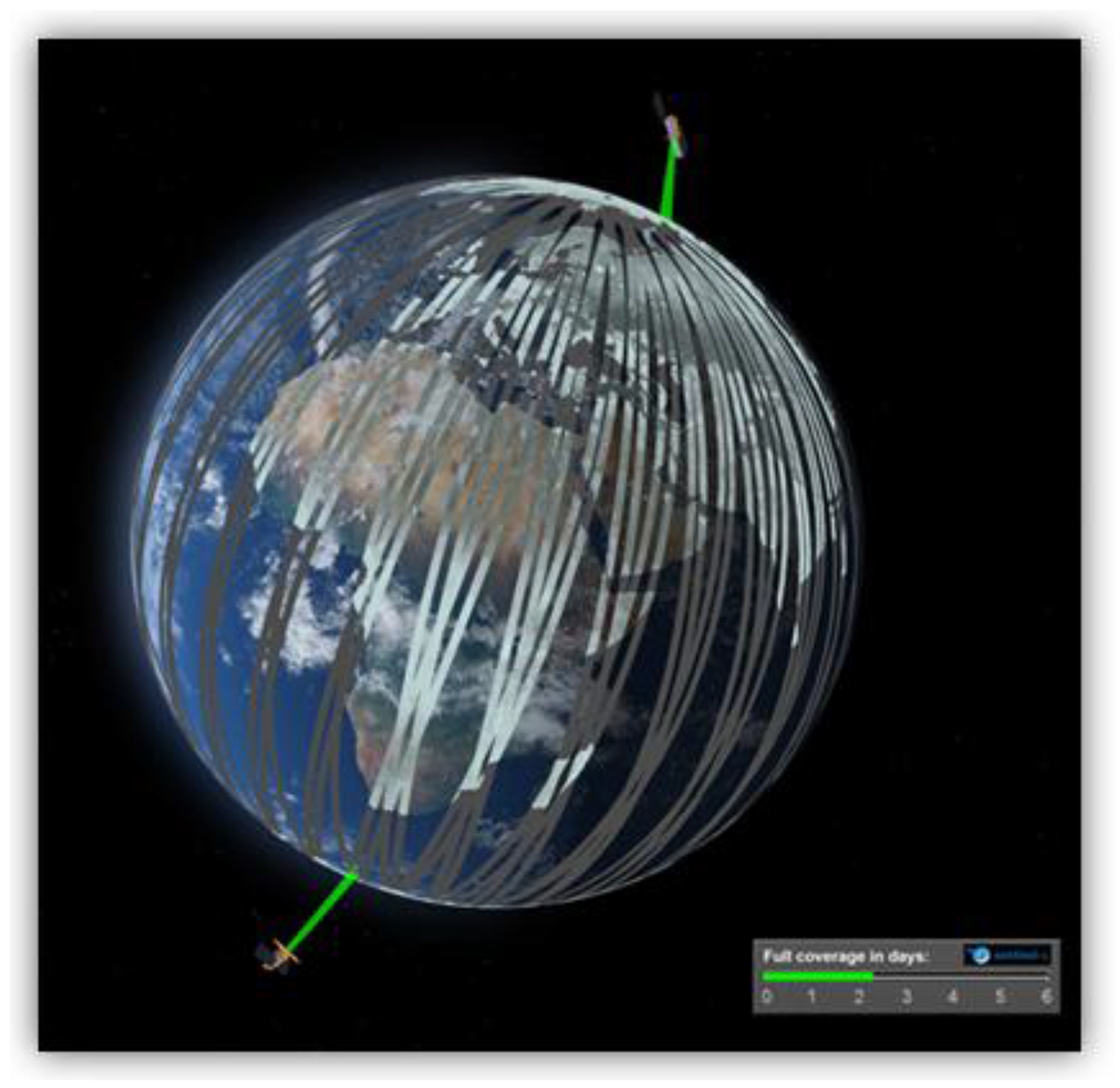
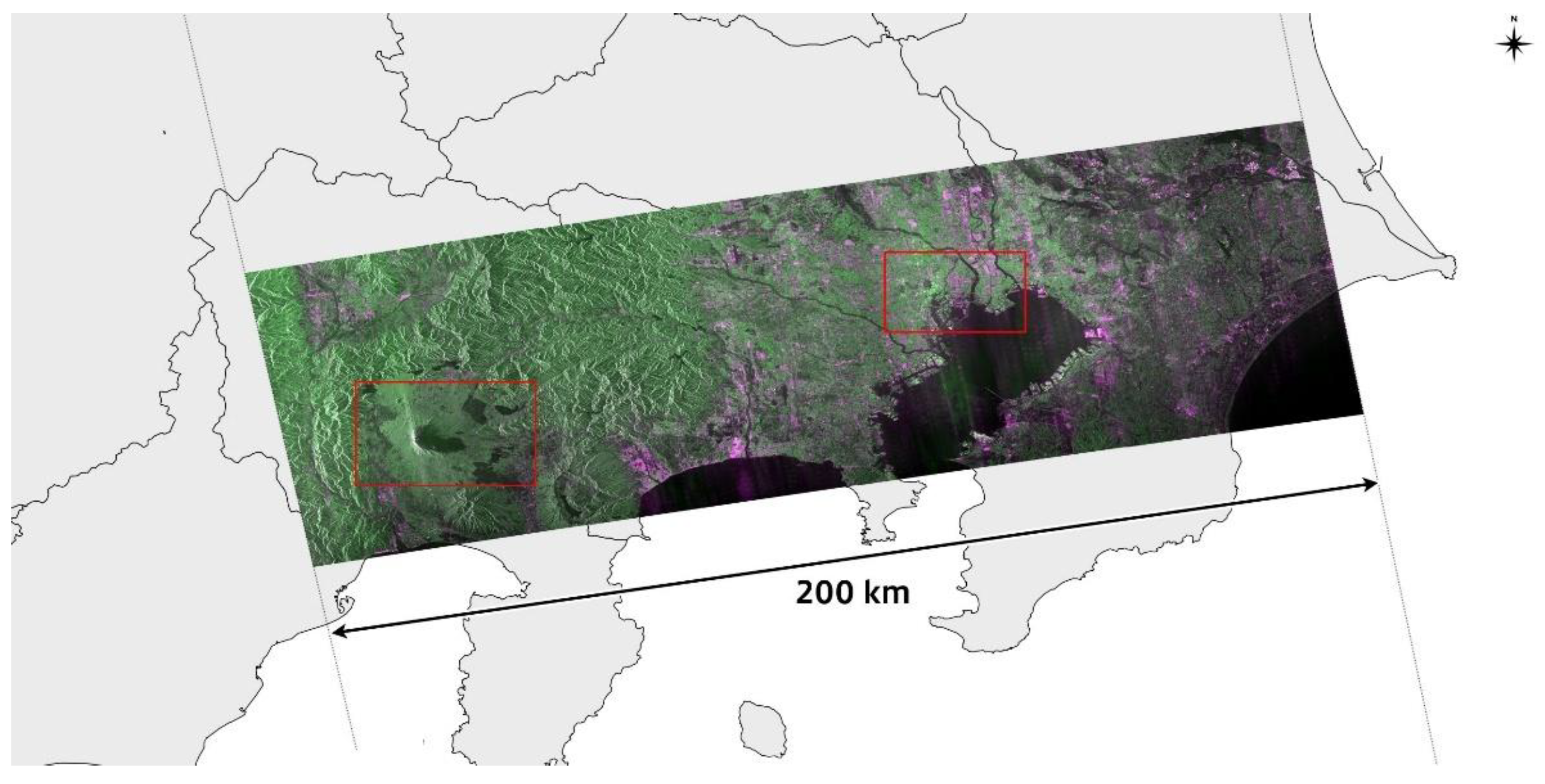
Since the launch of the first satellite, Sentinel-1A, in April 2014, the Sentinel-1 series has played a significant role in the field of Earth observation. In 2016, a second satellite, Sentinel-1B, was successfully launched, further enhancing the mission's capabilities. However, Sentinel-1B ended its mission early in August 2022 due to a technical glitch that prevented it from continuing to acquire data. The third Sentinel-1 satellite (Sentinel-1C) was successfully launched on December 5, 2024 by a Vega-C rocket from the European Spaceport in French Guiana. Equipped with the most advanced C-band synthetic Aperture radar (SAR) instrument, Sentinel-1C is capable of providing high-resolution images of the Earth's surface at all times and in all weather conditions, supporting a variety of critical applications such as environmental management, disaster response and climate change research. In addition, Sentinel-1C introduces an Automatic identification system (AIS) to enhance maritime traffic detection and monitoring capabilities, enabling accurate tracking of a ship's identity, location and direction of travel. Re-form a dual satellite constellation (consisting of two identical satellites in the same orbit but 180° apart) to ensure continuity and efficiency of Earth observation data.
Figure 18.
Sentinel-1 constellation configuration [87].
A large number of studies have shown that Sentinel-1 can continuously and effectively monitor surface deformation. Figure 19 shows Sentinel-1C's ability to monitor ice cover and environmental changes in harsh remote areas [88].
4.1.2. Multibeam
The European Space Agency's Earth Explorer 10 program has improved the Wavemill plan and launched the SEASTAR program [89,90], aiming to provide high-precision and high-resolution two-dimensional products of global ocean surface current vectors and wind vectors with a spatial resolution of 1 km, with a focus on global coastal areas, continental shelves, and marginal ice zones. To achieve global ocean surface current vector observations and simultaneous observations of wind vectors and waves, the European Space Agency has designed a DBI-Ku band dual-polarization SAR satellite. This satellite operates on a sun-synchronous orbit, alternating between rapid revisit orbits (with a repeat cycle of 1 to 2 days) and medium revisit orbits (with a repeat cycle of 5 to 20 days).
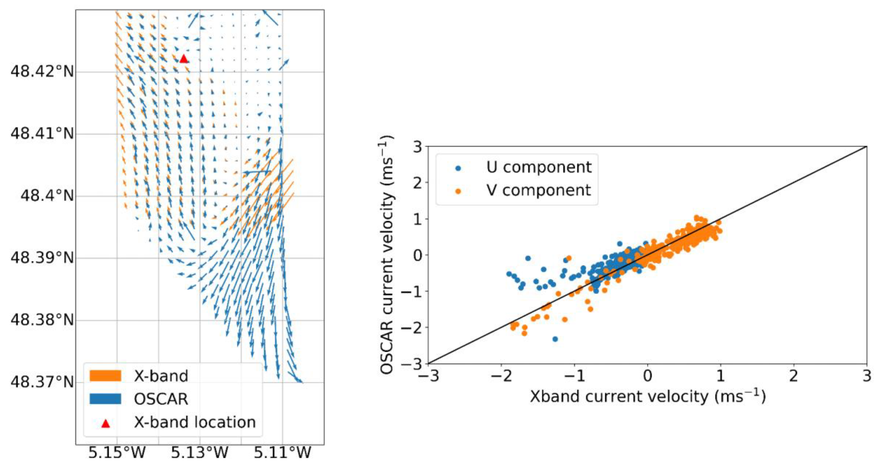
The Ocean Surface Current Airborne Radar (OSCAR) [91–95] is a new generation of airborne radar designed for SEASTAR, used to verify the ability of large-incidence angle three-view ATI-SAR to invert current fields and wind fields. In May 2022, OSCAR conducted flight tests in the Iriose Sea of France, and the results showed that at a resolution of 200 m, the RMSE of ocean currents compared to X-band radar was better than 0.2 m/s [91].
Figure 20.
Comparison of OSCAR and X band radar measurement results.
4.1.3. Multiband
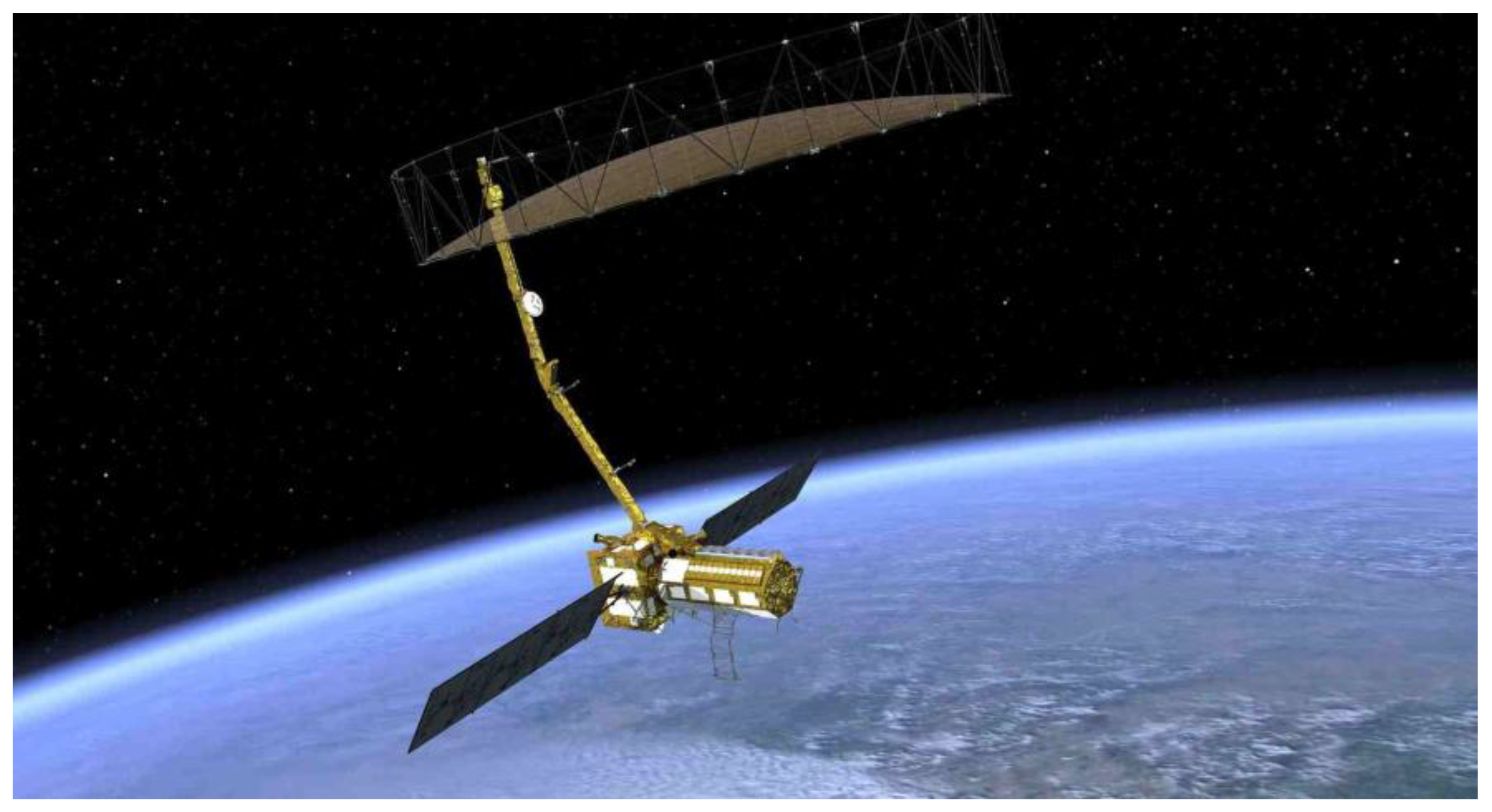
The NASA-ISRO Synthetic Aperture Radar (NISAR) is scheduled to be launched in March 2025. Developed by NASA and ISRO, it is primarily designed to monitor almost all land and ice surfaces on Earth every 12 days. Equipped with a dual-frequency radar system (L-band and S-band), it is used to track vegetation changes, measure ice sheet dynamics, monitor natural disasters such as earthquakes and landslides, and study long-term changes in Earth's structure and climate [96,97].
Figure 21.
NISAR satellite [98].
3.1.4. Multi-Baseline
On a single spaceborne platform, the resolution capability of interferometric synthetic aperture radar (InSAR) is limited. However, by having multiple spaceborne platforms work in coordination, the spatial and temporal resolution of the images can be significantly enhanced, and the formation of satellite constellations can cover broader and more detailed geographical areas. Moreover, formation interferometry technology can dynamically adjust the number of platforms and sensor layouts based on specific mission requirements, and can carry multiple sensors to achieve multi-band monitoring and meet the monitoring needs of different scenarios, thereby enriching the data.
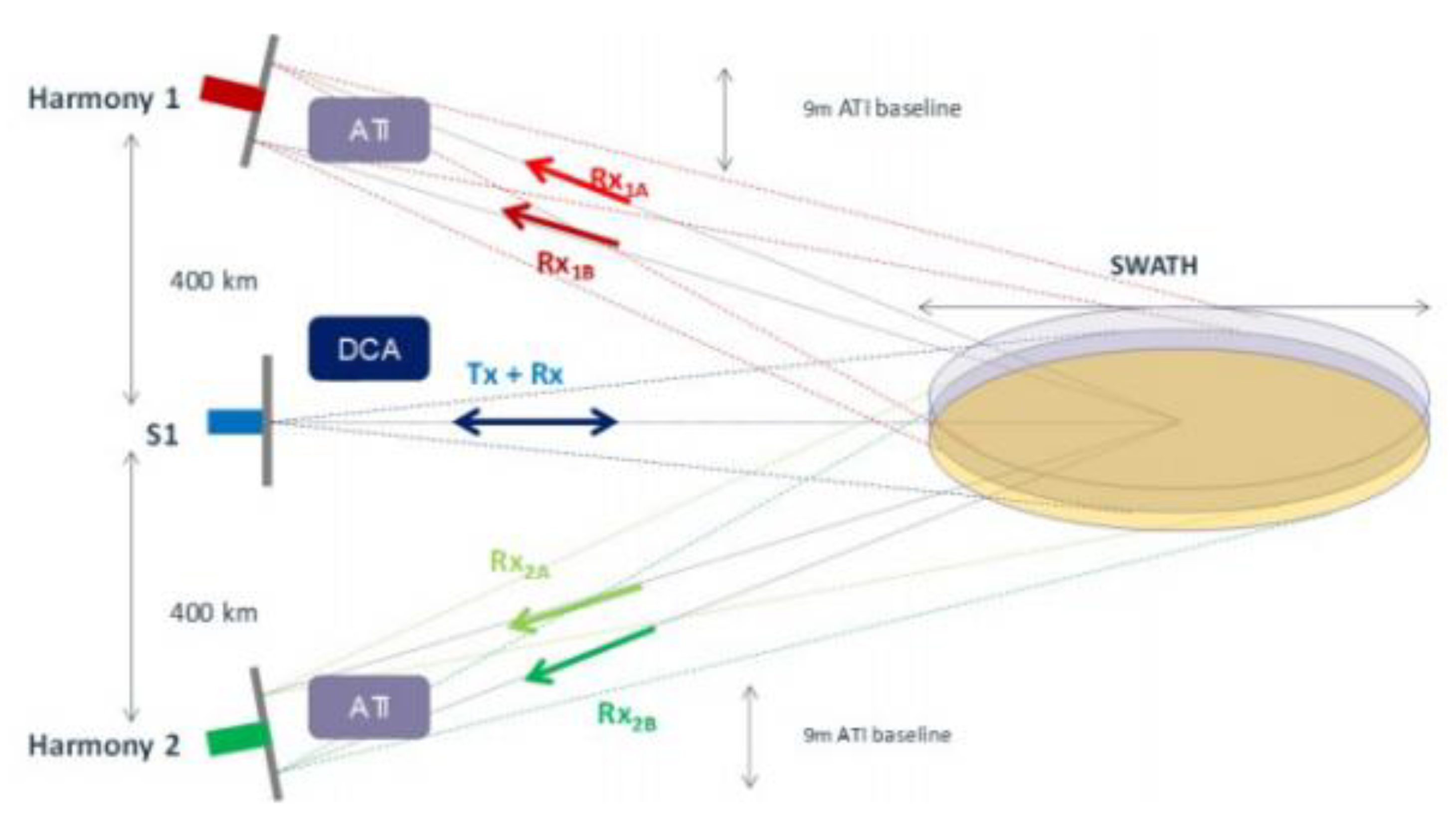
In 2019, at the IGRASS conference, the ESA announced the Harmony as a candidate for the Earth Observation 10 mission [99,100]. The Harmony project plans to launch two SAR satellites weighing less than 500 kg each, carrying only receivers, to receive echoes from Sentinel-1D. Their orbital configuration will be divided into two phases. In the first phase, Harmony-A and Harmony-B satellites will form a cross-track baseline and maintain it for over a year to study the seasonal changes of ice layers. In the second phase, B and A satellites will be distributed approximately 250 km ahead and behind Sentinel-1D, forming two pairs of along-track interferometric pairs to achieve a spatial resolution of 1 to 4 km and a sea surface velocity measurement accuracy of 0.15 m/s.
Figure 22.
Harmony formation configuration.
On April 30, 2019, the China TIANHUI-2 satellites were launched. The TIANHUI-2 can obtain InSAR data for the ground area between 75°S and 82°N latitude on the globe, mainly for the production of high-precision DEM, digital surface models (DSM), and radar orthophoto products [61,101]. The InSAR altitude measurement mode of the fly-by formation is the main working mode of TIANHUI-2. During a single pass, two satellites can obtain the coherent echo data of the same area on the ground in strips, and the data are transmitted to the ground for InSAR altitude measurement processing [102]. In the early stage of orbiting, the two satellites operated in the follow-up mode, with an inter-satellite distance of about 30 km. During this period, the SAR performance indicators of each satellite were tested, and on June 17, when the Sichuan Yibin earthquake occurred, the distance between the satellites was 5 km, and the satellite follow-up mode images of this area were obtained. DSM data were processed, as shown in Figure 24.
Figure 23.
TIANHUI-2 formation configuration. (a) Fly-around formation InSAR; (b) Follow-up formation InSAR.
Figure 23.
TIANHUI-2 formation configuration. (a) Fly-around formation InSAR; (b) Follow-up formation InSAR.
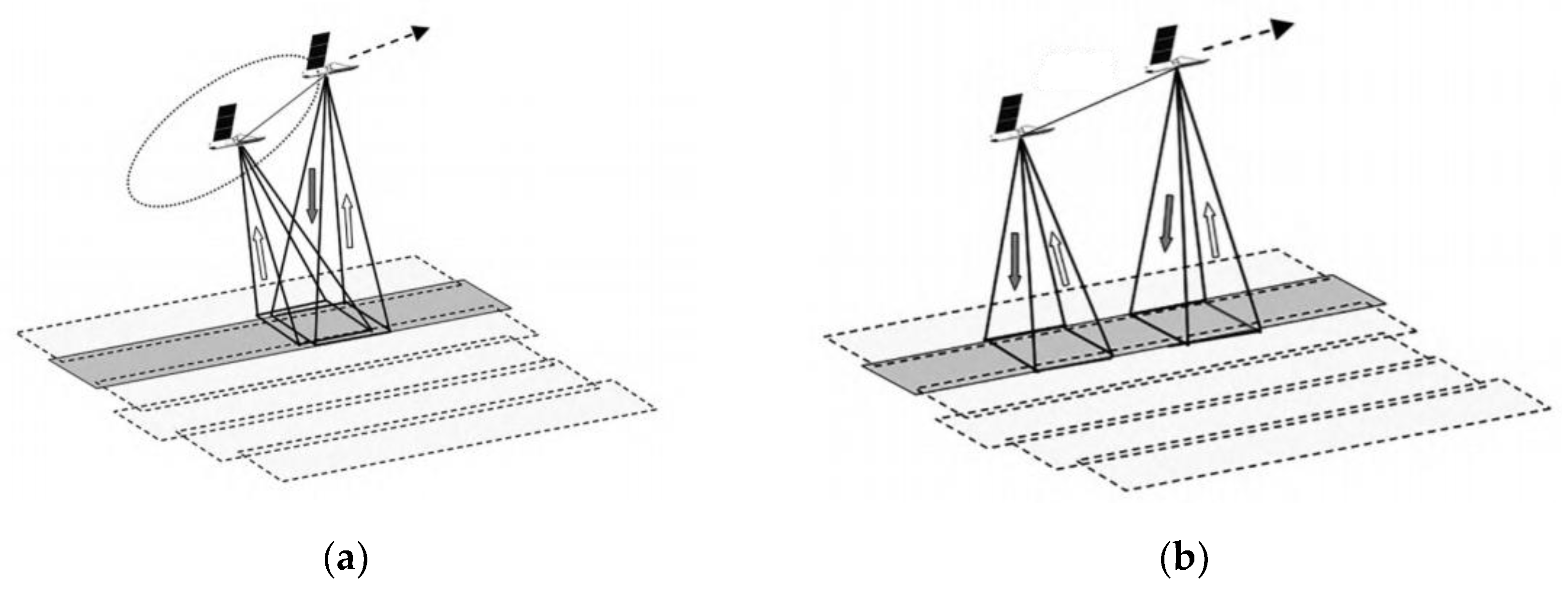
Figure 24.
DSM data in Follow-up mode.
On July 9, the system formed a fly-by formation configuration, with an effective baseline of about 500 m. The system was powered on and InSAR data were obtained that night. The data were transmitted to the ground system, and using self-developed software, the first DSM mapping product was successfully processed at one attempt, as shown in Figure 25. The successful launch of the TIANHUI-2 satellite enabled China’s microwave remote sensing to achieve a stepwise development from single-satellite observation to dual-satellite interferometric mapping, filling the gap in the field of distributed formation radar satellites in China, making China the second country in the world to have a microwave interferometric mapping satellite, and proposing for the first time an international method to solve the absolute ambiguity problem of interferometric phase through system design of dual-frequency imaging, completely getting rid of the dependence on control data. This was a major breakthrough in the construction of China’s aerospace surveying and mapping capabilities. Its all-weather and all-weather data acquisition capability, fast data processing speed, etc., can not only make up for the problem that optical mapping satellites cannot obtain data in areas with perennial cloudy and rainy weather, but also the DSM data obtained quickly can be directly used for the production of topographic maps and orthophotos of optical mapping satellites. This will greatly accelerate the speed of China’s global geographic spatial information construction [103]. The TIANHUI-2 satellite system adopts a dual-satellite inter-satellite fly-by formation and one-launch-dual-reception interferometric technology system, operating in a Sun-synchronous orbit at an altitude of 500 km. The in-orbit test results show that the system is in good operating condition, and its main performance indicators are superior to the design indicators. Its positioning accuracy is comparable to that of the German TDX system and can be used for the production of 1:50,000 scale geographic spatial information products.
On March 30, 2023, China PIESAT-1 satellite was launched. It forms a 1+3 wheel interference formation. Its main tasks are global land surveying and mapping, imaging observation, deformation monitoring, and elevation measurement. The elevation measurement accuracy reaches relative elevation accuracy (CE90) ≤ 3m (flat land, hilly land), 7m (mountainous land, highland land), and absolute elevation accuracy (CE90) ≤ 7m. The mapping accuracy is better than 1:50,000, and the deformation accuracy is 3-5mm/year.
Figure 26.
PIESAT-1 satellite formation.
PIESAT Information Technology Co.,Ltd. Provided the “ PIESAT-1” satellite constellation remote sensing image product set in 2024 [104]. On November 9, 2024, and December 17, 2024, four satellites were launched in one rocket in the form of one satellite per group, forming a 90-degree equip phase in-orbit formation, constituting a 1×4 Walker constellation system. Among them, one satellite serves as the backup satellite for the “ PIESAT-1” main satellite and operates in the main satellite’s orbit, with technical status basically consistent with the main satellite. The PIESAT-2 constellation has single-satellite high-resolution imaging, multi-satellite high-precision interferometric measurement, on-board data processing and autonomous planning, emergency communication and rapid response, as well as continuous and stable data production capabilities. It mainly conducts observation tasks such as global regional regular coverage, rapid revisit of specific areas, high-frequency monitoring of key targets, and emergency call for special scenarios, supporting and serving application demands in fields such as land resources, earthquake, disaster prevention and mitigation, acquisition of basic geographic information, and forestry. The satellites have played an important role in multiple emergency events such as monitoring of the rainstorm and flood disasters in Beijing-Tianjin-Hebei region in 2023, monitoring of the breach of Dongting Lake in Huarong County, Hunan Province, monitoring of rare heavy rain in Huludao, Liaoning Province, monitoring of forest fires and damage in the Abei Forest Farm of Inner Mongolia Forestry Industry, and monitoring of the collapse of the Meida Expressway in Taubao, Guangdong Province. They have supported monitoring of various events more than a hundred times and generated over 500,000 standard image data, covering the entire country.
Figure 27.
DSM and DEM published by PIESAT Information Technology Co.,Ltd (a) Plain Area Data in Laos; (b) Hilly Area Data in Laos; (c) Mountainous and Highland Areas Data in Laos; (d) DEM of the Central Region of Bulgaria.
Figure 27.
DSM and DEM published by PIESAT Information Technology Co.,Ltd (a) Plain Area Data in Laos; (b) Hilly Area Data in Laos; (c) Mountainous and Highland Areas Data in Laos; (d) DEM of the Central Region of Bulgaria.
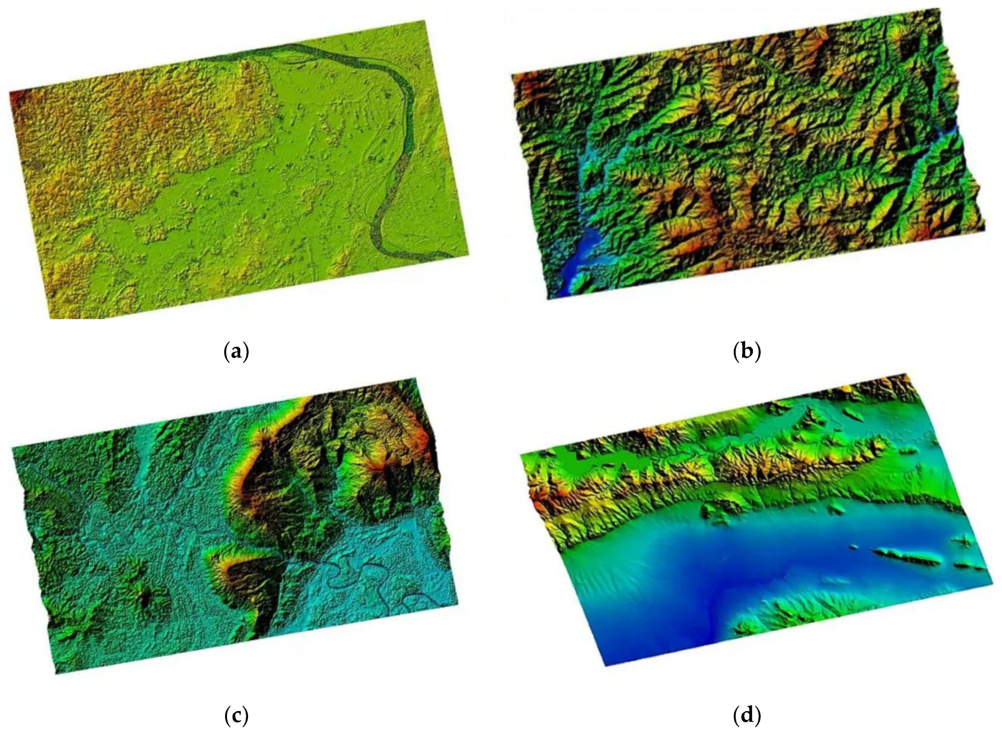
Based on the Digital Surface Model (DSM) products, digital elevation model (DEM) products are generated. The terrain features of the DEM products are clearly visible. The terrain details of mountains, rivers and flatlands are very distinct. Moreover, the high-precision DEM products can ensure the accuracy of terrain analysis and the precision of hydrological modeling, providing reliable data support for various industries' analyses.
Figure 28.
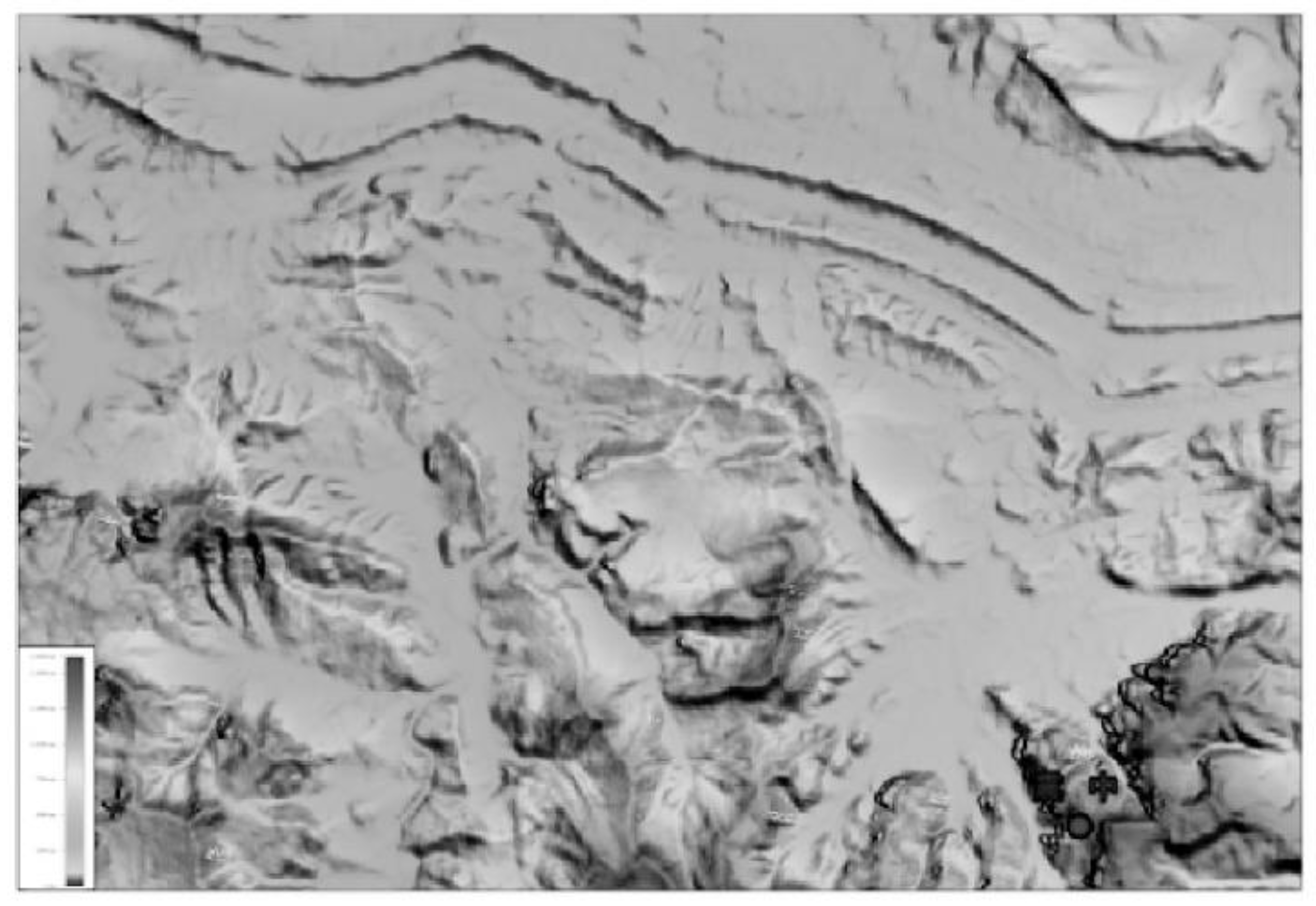
Deformation Monitoring of Muruntau Gold Mine in Uzbekistan.

4.2. High-Frame-Rate
To address the issues of small imaging swath width and long revisit time of low-orbit SAR satellites in imaging the observation area, the Earth-Synchronous Synthetic Aperture Radar (GEO SAR) [105] emerged. By taking advantage of the orbital position of the Earth-Synchronous Orbit, the revisit period for the same location can be increased from the sub-day level of low-orbit SAR to the hour level, and the imaging swath width can be expanded from the hundreds of kilometers of low-orbit SAR to the thousands of kilometers. By improving the temporal resolution of the same observation scene, high-frame-rate SAR images, namely the high-temporal mode, can be obtained, which extends the information to three dimensions. The additional temporal dimension provides more spatio-temporal degrees of freedom. It can provide strong support for timely and effective implementation of disaster emergency response.
The concept of high-orbit SAR satellites was first proposed in 1978 [106], and it remains a research hotspot to this day. NASA of the United States, Cranfield University of the United Kingdom [107], Politecnico di Milano of Italy [108], Vega Company of Russia, China Academy of Space Technology, and other research institutions [109–111] are all conducting research on high-orbit SAR.
Figure 29.
LT-4(01) Satellite configuration (CAST).
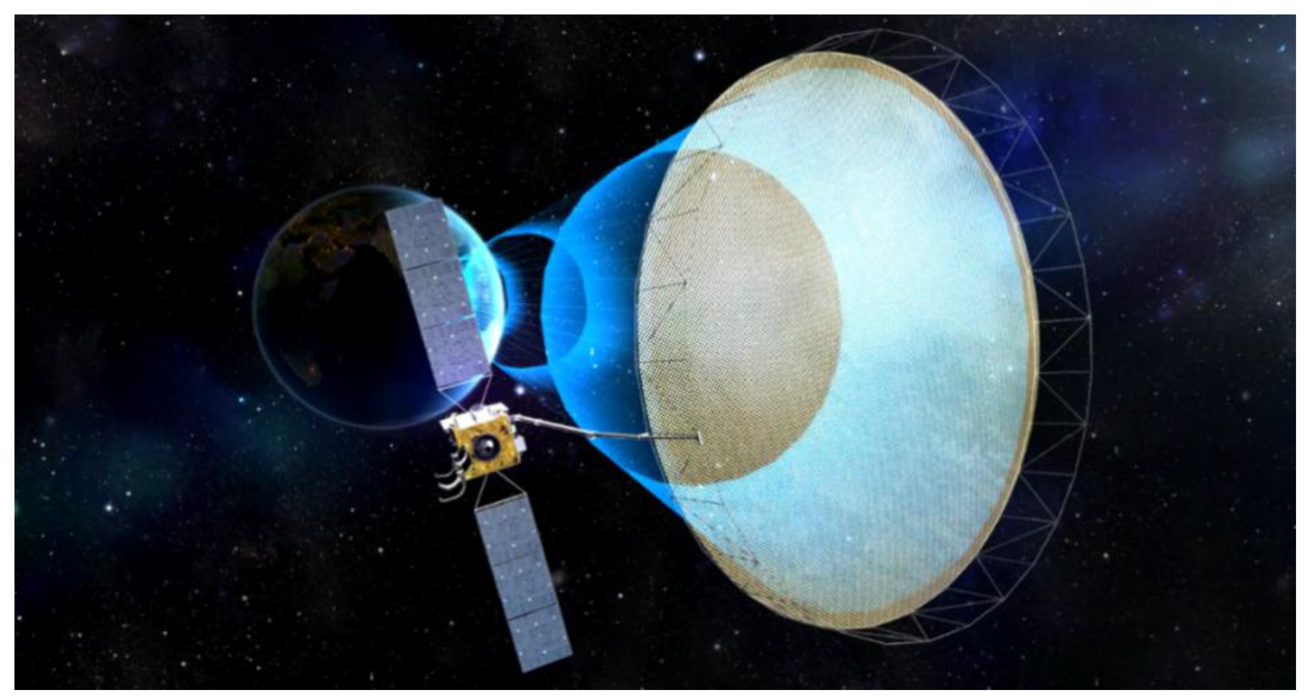
On August 13, 2023, China's LT-4(01) satellite was launched, becoming the world's first Earth-synchronous orbit SAR satellite [111]. The synthetic aperture radar payload carried by the LT-4(01) satellite has advantages such as high resolution, wide coverage, multi-mode, and lightweight. Besides adopting synthetic aperture radar technology, this satellite has another feature, that is, its operating orbit is exceptionally high, about 40,000 kilometers away from the Earth. The higher it flies, the farther it can see.
Figure 30.
LT-4(01) Satellite work diagram (CAST).
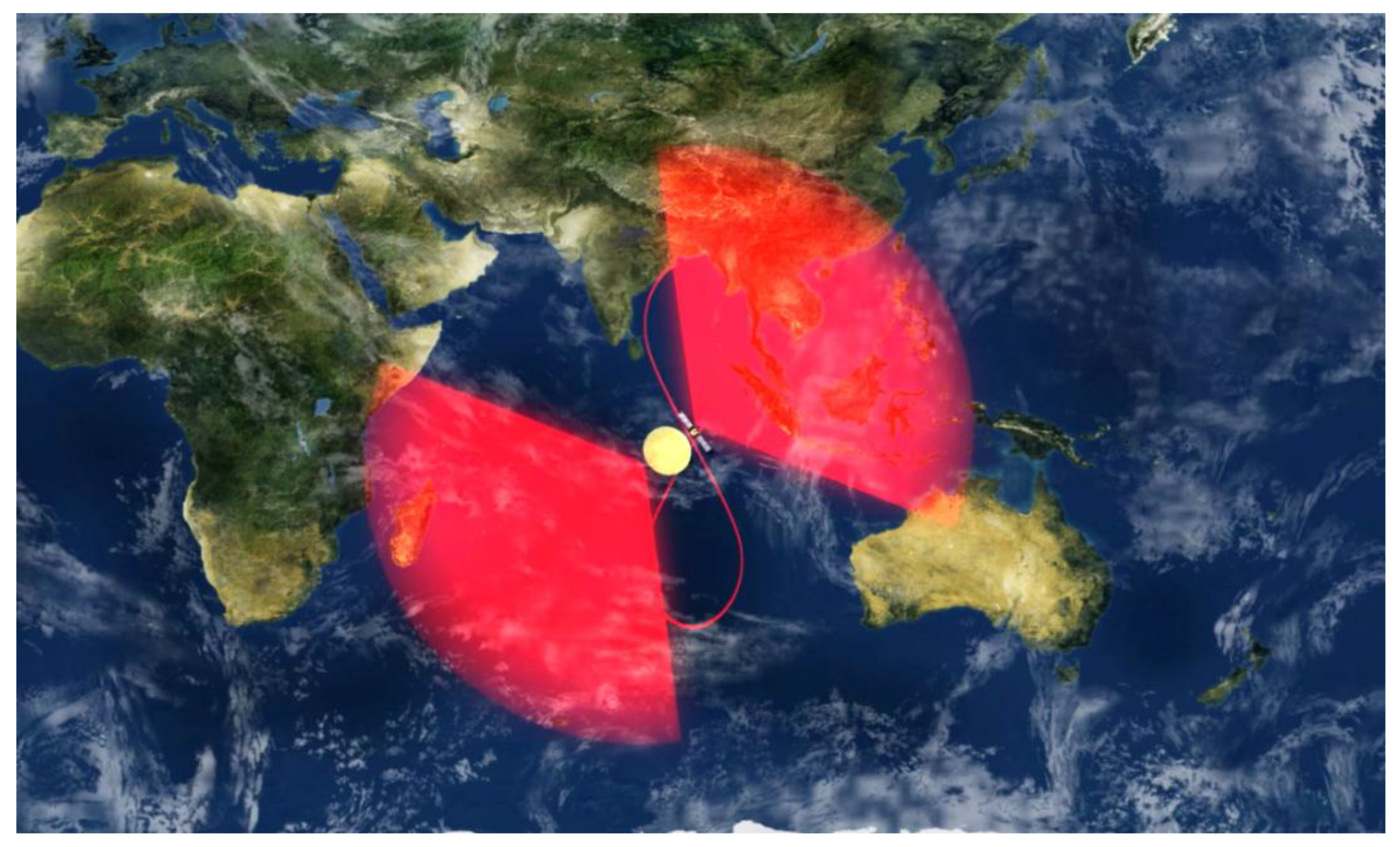
The LT-4(01) satellite operates in an inclined geosynchronous orbit at a distance of nearly 40,000 kilometers from the Earth. Satellites operating on this orbit resemble repeatedly drawing an "8" shape in the sky, enabling relatively continuous observations of a fixed large area. The observation revisit period is short and the imaging swath is wide. Compared with low-orbit satellites and optical satellites, the LT-4(01) satellite combines the advantages of short high-orbit observation revisit periods and wide imaging swaths with the advantages of microwave observation that is not limited by weather conditions (all-weather) and not limited by lighting conditions (all-time). This can improve the recognition accuracy and efficiency of abnormal changes in disaster information and enhance the comprehensive prevention and control capabilities for natural disasters. In the development of the LT-4(01) satellite project, an innovative scheme of a large-aperture annular reflector antenna and phased array feed was proposed for the first time and implemented engineering-wise [112]. The imaging maximum swath of the high-orbit SAR satellite can reach 3,000 km. It has the ability to conduct a full-basin observation of potential flood disasters in the Yangtze River and Yellow River basins. Operating in the scanning mode (50m/3000km), it can complete the coverage of the entire country within 3 days and form a national map. The same efficacy can only be achieved by networking 5 low-orbit SAR satellites.
Figure 31.
LT-4(01) Satellite scanning (CAST).
4.3. PolInSAR
In 1997, S.R. Cloude and K.P. Papathanassiou [113] first studied the impact of frequency and polarization on coherence using SIR-C/X-SAR data, and found that coherence strongly depends on polarization, pioneering research in the field of multipolarization SAR interferometry. Polarimetric SAR interferometry (PolInSAR) offers unique advantages that conventional SAR cannot match, and has gradually become a new research hotspot in the field of SAR data processing [75,114–116]. The TanDEM-X satellite successfully conducted a coordinated flight with the TerraSAR-X satellite in June 2010, forming the world's first single-pass polarimetric interferometric radar system. This system enabled the acquisition of spaceborne polarimetric synthetic aperture radar interferometry (PolInSAR) data without the interference of temporal decorrelation. Kugler et al. [115] applied this technology for forest height inversion and validated its effectiveness under different forest structures and seasonal conditions. In recent years, significant progress has been made in the application of PolInSAR technology for surface vegetation height inversion [117]. With the continued use of both full-polarization and dual-polarization synthetic aperture radar data, PolInSAR has expanded its applications in forest biomass estimation, carbon stock assessment, and tropical forest monitoring.
Figure 32.
The inversion results of dual polarization SAR data are processed by interference method [118].
Figure 32.
The inversion results of dual polarization SAR data are processed by interference method [118].
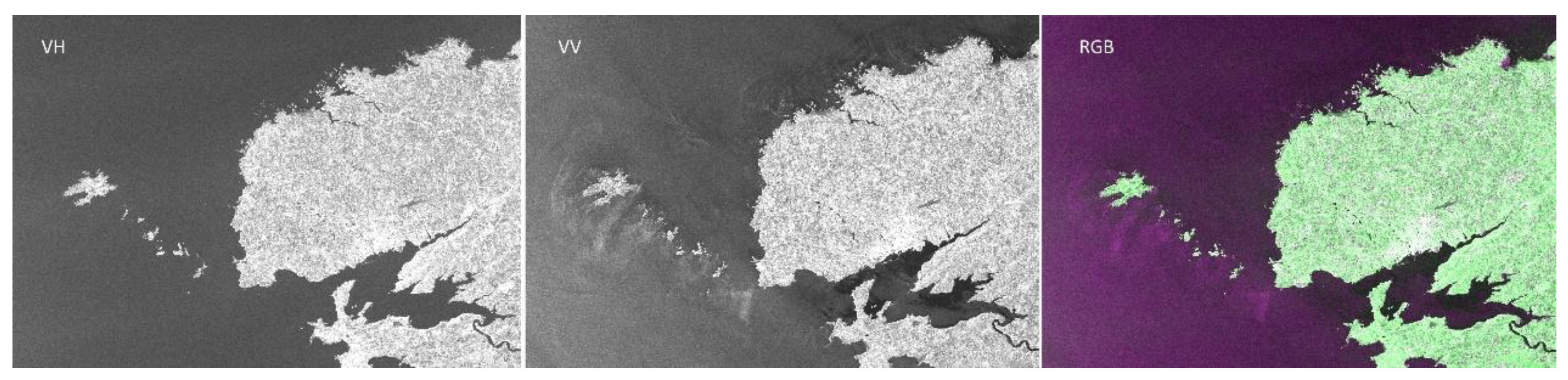
2015, Fu et al. [118] proposed a PolInSAR technique based on dual-polarization SAR data and successfully applied it to forest height estimation by extending the three-stage inversion process and coherence optimization algorithm. Experimental results show that dual-polarization PolInSAR performs comparably to the full-polarization mode, and the proposed volume-only coherence search method significantly enhances inversion accuracy. Figure 36 shows the grayscale of Sentinel-1A under different polarization modes.
Figure 33.
Image acquired by Copernicus Sentinel-1A on 2017/11/01 over Brittany region, France, with VV intensity image, VH intensity image, and RGB color composite. Copernicus Sentinel data (2017) processed by CLS.[87].
Figure 33.
Image acquired by Copernicus Sentinel-1A on 2017/11/01 over Brittany region, France, with VV intensity image, VH intensity image, and RGB color composite. Copernicus Sentinel data (2017) processed by CLS.[87].
4.4. HRWS
Japan launched the Advanced Land Observing Satellite-4 (ALOS-4) on July 1, 2024. The Japan Aerospace Exploration Agency (JAXA) released the first observation images captured by the L-band synthetic aperture radar (PALSAR-3) aboard the satellite from July 15 to 17, 2024 (Japan Standard Time) (Figure 38). "ALOS-4" is the first radar satellite to implement digital beamforming technology on an artificial satellite. While maintaining the high spatial resolution of the previous "ALOS-2", it has expanded the observation range by up to 4 times (200 km wide at a 3m resolution). It is expected to contribute to disaster situation understanding, environmental observations such as forest distribution, and marine observations such as sea ice, together with "ALOS-2".
Figure 34.
ALOS-4 satellite.
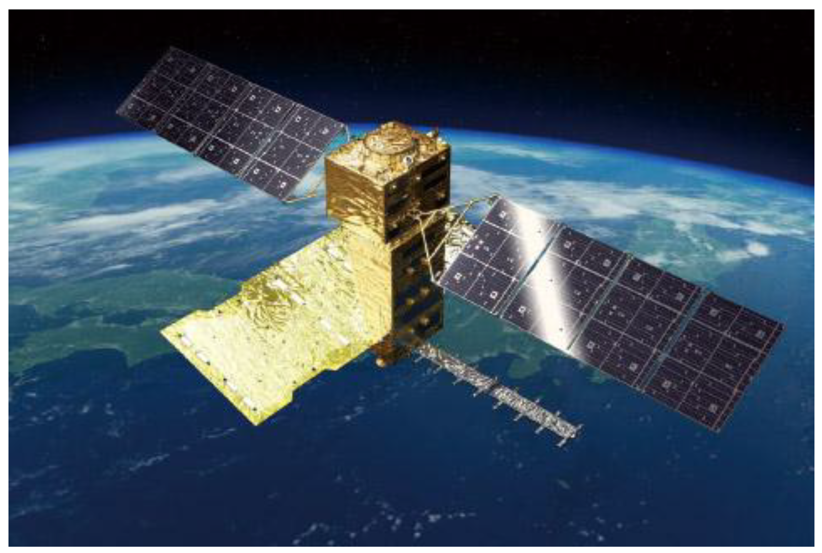
Figure 35.
Observation Map of ALOS-4 on July 15 in the Kanto Region of Japan (3m resolution, 200km width)[119].
Figure 35.
Observation Map of ALOS-4 on July 15 in the Kanto Region of Japan (3m resolution, 200km width)[119].
5. Conclusions
The InSAR technology progress and development trends introduced in this article mainly include repeat-pass interferometry, single-pass interferometry and polarization interferometry. In recent years, the number of launched SAR satellites has been increasing continuously, especially after commercial satellite companies joined the ranks of developing and launching SAR satellites. Moreover, due to the limitations of weather conditions that optical satellites cannot achieve all-weather earth observation, countries around the world need SAR satellites to fill the observation gaps of optical satellites.
Repeat-pass interferometry includes D-InSAR technology, PS-InSAR technology and SBAS-InSAR technology, and its main application field is surface deformation observation. The traditional repeat-pass interferometry has a long revisit period, which cannot meet the timeliness requirements of emergency disaster reduction. Earth-synchronous orbit SAR satellites have a short revisit period and are not affected by weather and night images, which can achieve high-precision feedback of surface deformation products and timely warning.
Single-pass interferometry includes CT-InSAR and AT-InSAR technologies. CT-InSAR technology is mainly applied in DEM and DSM generation, as well as sea surface elevation measurement, while AT-InSAR technology is mainly applied in sea surface flow field measurement and moving target detection. Traditional single-baseline earth observation has a single dimension, and fixed baselines cannot adapt to different terrains and sea conditions. Developing towards multi-satellite and multi-baseline is conducive to achieving multi-dimensional high-precision measurement.
Polarization interferometry has developed from single-polarization to multi-polarization. Different polarization information can effectively help classification and identification, and has played a huge role in promoting applications such as forest biomass estimation and forest height estimation.
Author Contributions
Conceptualization, Q.J.Z. and F.H.J.; methodology, Q.J.Z. and F.H.J.; formal analysis, Q.J.Z. , Y.S.Z. and F.H.J.; investigation, F.H.J.; resources, Q.J.Z. and Y.S.Z.; data curation, Y.X.Q. and F.H.J.; writing—original draft preparation, Q.J.Z. and F.H.J.; writing—review and editing, F.H.J. and Y.X.Q.; visualization, Y.S.Z. and F.H.J.; supervision, Y.X.Q. and Y.S.Z.; project administration, Q.J.Z. and F.H.J.; funding acquisition, Q.J.Z. and Y.S.Z. All authors have read and agreed to the published version of the manuscript.
Funding
This work was supported in part by the National Science Fund under Grant 62201573 and 62031005. This work is supported in part by National Key R&D Program of China #2023YFB3904902, #2023YFB3904900.
Acknowledgments
The authors appreciate the anonymous referees for good suggestions in improving the paper quality.
Conflicts of Interest
The authors declare no conflicts of interest.
References
- DENG Yunkai; YU Weidong; ZHANG Heng; WANG Wei; LIU Dacheng; WANG Robert. Forthcoming Spaceborne SAR Development. Journal of Radars 2020, 9, 1–33. [Google Scholar]
- CHEN Junli; LIU Yanyang; CHEN Zhonghua; ZHAO Di. Spaceborne Interferometric Synthetic Aperture Radar: Status and Prospect. Aerospace Shanghai(Chinese&English) 2021, 38, 96–108. [Google Scholar]
- LI Zhenhong; ZHU Wu; YU Chen; ZHANG Qin; ZHNAG Chenglong; LIU Zhenjiang; ZHANG Xuesong; CHEN Bo; DU Jiantao; SONG Chuang; HAN Bingquan; ZHOU Jiawei. Interferometric synthetic aperture radar for deformation mapping: opportunities, challenges and the outlook. Acta Geodaetica et Cartographica Sinica 2022, 51, 1485–1519. [Google Scholar]
- Ouchi, K. Recent Trend and Advance of Synthetic Aperture Radar with Selected Topics. Remote Sensing 2013, 5, 716–807. [Google Scholar] [CrossRef]
- Yi SHAO; Zhiwei ZHOU; Peifeng MA; Teng WANG. A review of intelligent InSAR data processing: recent advancements, challenges and prospects. Acta Geodaetica et Cartographica Sinica 2024, 53, 1037–1056. [Google Scholar]
- HE Shan; WU Han; LI Jilong. A Review of the Application of InSAR Technology in Digital Terrain Analysis. Science & Technology Vision 2024, 14, 60–64. [Google Scholar]
- WANG Xiaying. Key techniques and their application of InSAR in ground deformation monitoring. Acta Geodaetica et Cartographica Sinica 2022, 51(10), 2244–2244. [Google Scholar]
- ZHAO Xia; MA Xinyan; YU Qian; WANG Zhaobing. Application of high-resolution InSAR technique in monitoring deformations in the Beijing Daxing International Airport. Remote Sensing for Natural Resources 2024, 36, 49–57. [Google Scholar]
- YI Jianfeng; ZHANG Qingjun; LIU Jie; ZHANG Running; ZHAO Lingbo; ZHANG Chi; LIU Yongli. A Review on Development of Formation Flying Interferometric SAR Satellite System. Spacecraft Engineering 2018, 27, 116–122. [Google Scholar]
- Rogers, A.E.E.; Ingalls, R.P. Venus: Mapping the Surface Reflectivity by Radar Interferometry. Science 1969, 165, 797–799. [Google Scholar] [CrossRef]
- Graham, L.C. Synthetic Interferometer Radar for Topographic Mapping. Proceedings of the IEEE 1974, 62, 763–768. [Google Scholar] [CrossRef]
- Zebker, H.A.; Goldstein, R.M. Topographic Mapping from Interferometric Synthetic Aperture Radar Observations. Journal of Geophysical Research: Solid Earth 1986, 91, 4993–4999. [Google Scholar] [CrossRef]
- Krieger, G.; Moreira, A.; Fiedler, H.; Hajnsek, I.; Werner, M.; Younis, M.; Zink, M. TanDEM-X: A Satellite Formation for High-Resolution SAR Interferometry. IEEE Trans. Geosci. Remote Sensing 2007, 45, 3317–3341. [Google Scholar] [CrossRef]
- Werner, M. Operating the X-Band SAR Interferometer of the SRTM. In Proceedings of the IGARSS 2000. IEEE 2000 International Geoscience and Remote Sensing Symposium. Taking the Pulse of the Planet: The Role of Remote Sensing in Managing the Environment. Proceedings (Cat. No.00CH37120); 2000; Vol. 6, pp. 2587–2589. [Google Scholar]
- Moreira, A.; Prats-Iraola, P.; Younis, M.; Krieger, G.; Hajnsek, I.; Papathanassiou, K.P. A Tutorial on Synthetic Aperture Radar. IEEE Geoscience and Remote Sensing Magazine 2013, 1, 6–43. [Google Scholar] [CrossRef]
- Gabriel, A.K.; Goldstein, R.M.; Zebker, H.A. Mapping Small Elevation Changes over Large Areas: Differential Radar Interferometry. Journal of Geophysical Research: Solid Earth 1989, 94, 9183–9191. [Google Scholar] [CrossRef]
- Massonnet, D.; Rossi, M.; Carmona, C.; Adragna, F.; Peltzer, G.; Feigl, K.; Rabaute, T. The Displacement Field of the Landers Earthquake Mapped by Radar Interferometry. Nature 1993, 364, 138–142. [Google Scholar] [CrossRef]
- Hanssen, R. Radar Interferometry: Data Interpretation and Error Analysis. Available online: https://www.semanticscholar.org/paper/Radar-Interferometry%3A-Data-Interpretation-and-Error-Hanssen/341cfe9b84770bed948a6113fd98b71ed380bc07 (accessed on 24 January 2025).
- LIU Guoxiang. Principles and applications of InSAR; Science Press: BeiJing, 2019; ISBN 978-7-03-061185-7. [Google Scholar]
- Monserrat, O.; Crosetto, M.; Luzi, G. A Review of Ground-Based SAR Interferometry for Deformation Measurement. ISPRS Journal of Photogrammetry and Remote Sensing 2014, 93, 40–48. [Google Scholar] [CrossRef]
- Chao, M.; Guifang, Z.; Xuedong, M.; Xinjian, S.; Fangfang, L.; Xiaoke, Z. A Model of In-Depth Displacement under Ms8.1 at Kunlun Earthquake with D-InSAR Co-Seismic Deformation Field. In Proceedings of the 2009 Sixth International Conference on Fuzzy Systems and Knowledge Discovery, August 2009; Vol. 5, pp. 141–144. [Google Scholar]
- Zhu, B.; Chen, H.; Wang, Y. Evaluating the Impact of the 2008 China Wenchuan Earthquake on Airports by Insar Technology and Palsar Data. In Proceedings of the IGARSS 2024 - 2024 IEEE International Geoscience and Remote Sensing Symposium, July 2024; pp. 3461–3464. [Google Scholar]
- Wright, T.; Fielding, E.; Parsons, B. Triggered Slip: Observations of the 17 August 1999 Izmit (Turkey) Earthquake Using Radar Interferometry. Geophysical Research Letters 2001, 28, 1079–1082. [Google Scholar] [CrossRef]
- Rott, H. Advances in Interferometric Synthetic Aperture Radar (InSAR) in Earth System Science. Progress in Physical Geography 2009, 33, 769–791. [Google Scholar] [CrossRef]
- LIU Guoxiang; DING Xiaoli; LI Zhiwei; CHEN Yongqi; LI Yonglin; YU Shuipei. ERS Satellite Radar Interferometry: Pre-earthquake and Coseismic Surface Displacements of the 1999 Taiwan Jiji Earthquake. CHINESE JOURNAL OF GEOPHYSICS 2002, 45, 165–174. [Google Scholar]
- Peltzer, G.; Rosen, P. Surface Displacement of the 17 May 1993 Eureka Valley, California, Earthquake Observed by SAR Interferometry. Science 1995, 268, 1333–1336. [Google Scholar] [CrossRef] [PubMed]
- Hu, J.; Li, Z.W.; Ding, X.L.; Zhu, J.J.; Zhang, L.; Sun, Q. Resolving Three-Dimensional Surface Displacements from InSAR Measurements: A Review. Earth-Science Reviews 2014, 133, 1–17. [Google Scholar] [CrossRef]
- Pritchard, M.E.; Simons, M. A Satellite Geodetic Survey of Large-Scale Deformation of Volcanic Centres in the Central Andes. Nature 2002, 418, 167–171. [Google Scholar] [CrossRef]
- Talebian, M.; Fielding, E.J.; Funning, G.J.; Ghorashi, M.; Jackson, J.; Nazari, H.; Parsons, B.; Priestley, K.; Rosen, P.A.; Walker, R.; et al. The 2003 Bam (Iran) Earthquake: Rupture of a Blind Strike-Slip Fault. Geophysical Research Letters 2004, 31. [Google Scholar] [CrossRef]
- Wright, T. The Earthquake Deformation Cycle. Astronomy & Geophysics 2016, 57, 20–26. [Google Scholar] [CrossRef]
- Wang, X.; Liu, G.; Yu, B.; Dai, K.; Zhang, R.; Chen, Q.; Li, Z. 3D Coseismic Deformations and Source Parameters of the 2010 Yushu Earthquake (China) Inferred from DInSAR and Multiple-Aperture InSAR Measurements. Remote Sensing of Environment 2014, 152, 174–189. [Google Scholar] [CrossRef]
- Xu, C.; Xu, B.; Wen, Y.; Liu, Y. Heterogeneous Fault Mechanisms of the 6 October 2008 MW 6.3 Dangxiong (Tibet) Earthquake Using Interferometric Synthetic Aperture Radar Observations. Remote Sensing 2016, 8, 228. [Google Scholar] [CrossRef]
- A map of surface deformation with a resolution of 40 meters nationwide and an accuracy of 5 mm/year [EB/OL]. Available online: http://www.hbeos.org.cn/xwzx/1/2022-08-22/867.html (accessed on 24 January 2025).
- China's first supercomputing InSAR system achieves nationwide surface deformation monitoring ---- Chinese Academy of Sciences [EB/OL]. Available online: https://www.cas.cn/syky/202012/t20201216_4770987.shtml (accessed on 24 January 2025).
- Duan, W.; Zhang, H.; Wang, C.; Tang, Y. Multi-Temporal InSAR Parallel Processing for Sentinel-1 Large-Scale Surface Deformation Mapping. Remote Sensing 2020, 12, 3749. [Google Scholar] [CrossRef]
- Song, C.; Yu, C.; Li, Z.; Utili, S.; Frattini, P.; Crosta, G.; Peng, J. Triggering and Recovery of Earthquake Accelerated Landslides in Central Italy Revealed by Satellite Radar Observations. Nat Commun 2022, 13, 7278. [Google Scholar] [CrossRef]
- Ferretti, A.; Prati, C.; Rocca, F. Permanent Scatterers in SAR Interferometry. IEEE Transactions on Geoscience and Remote Sensing 2001, 39, 8–20. [Google Scholar] [CrossRef]
- Ferretti, A.; Savio, G.; Barzaghi, R.; Borghi, A.; Musazzi, S.; Novali, F.; Prati, C.; Rocca, F. Submillimeter Accuracy of InSAR Time Series: Experimental Validation. IEEE Transactions on Geoscience and Remote Sensing 2007, 45, 1142–1153. [Google Scholar] [CrossRef]
- Ferretti, A.; Prati, C.; Rocca, F. Nonlinear Subsidence Rate Estimation Using Permanent Scatterers in Differential SAR Interferometry. IEEE Transactions on Geoscience and Remote Sensing 2000, 38, 2202–2212. [Google Scholar] [CrossRef]
- Adam, N.; Kampes, B.; Eineder, M. DEVELOPMENT OF A SCIENTIFIC PERMANENT SCATTERER SYSTEM: MODIFICATIONS FOR MIXED ERS/ENVISAT TIME SERIES. 2004. [Google Scholar]
- Hooper, A.; Zebker, H.; Segall, P.; Kampes, B. A New Method for Measuring Deformation on Volcanoes and Other Natural Terrains Using InSAR Persistent Scatterers. Geophysical Research Letters 2004, 31. [Google Scholar] [CrossRef]
- Ferretti, A.; Fumagalli, A.; Novali, F.; Prati, C.; Rocca, F.; Rucci, A. A New Algorithm for Processing Interferometric Data-Stacks: SqueeSAR. IEEE Transactions on Geoscience and Remote Sensing 2011, 49, 3460–3470. [Google Scholar] [CrossRef]
- Huang, S.A.; Sauber, J.M. Leveraging Multi-Primary PS-InSAR Configurations for the Robust Estimation of Coastal Subsidence. IEEE Geoscience and Remote Sensing Letters 2024, 21, 1–5. [Google Scholar] [CrossRef]
- Nyoman Sudi Parwata, I.; Osawa, T. Surface Deformation Monitoring Induced by Volcanic Activity of Mount Agung, Indonesia, by PS-InSAR Using Sentinel-1 SAR from 2014-2021. In Proceedings of the 2021 7th Asia-Pacific Conference on Synthetic Aperture Radar (APSAR), November 2021; pp. 1–4. [Google Scholar]
- Xu, J.; Gu, S.; Li, J.; Tian, X.; Li, L.; Xu, S. Monitoring and Risk Assessment of Urban Surface Deformation Based on PS-InSAR Technology: A Case Study of Nanjing City. IEEE Journal on Miniaturization for Air and Space Systems 2024, 5, 73–78. [Google Scholar] [CrossRef]
- Berardino, P.; Fornaro, G.; Lanari, R.; Sansosti, E. A New Algorithm for Surface Deformation Monitoring Based on Small Baseline Differential SAR Interferograms. IEEE Transactions on Geoscience and Remote Sensing 2002, 40, 2375–2383. [Google Scholar] [CrossRef]
- Lauknes, T.R.; Zebker, H.A.; Larsen, Y. InSAR Deformation Time Series Using an L₁ -Norm Small-Baseline Approach. IEEE Transactions on Geoscience and Remote Sensing 2011, 49, 536–546. [Google Scholar] [CrossRef]
- Casu, F.; Manconi, A.; Pepe, A.; Lanari, R. Deformation Time-Series Generation in Areas Characterized by Large Displacement Dynamics: The SAR Amplitude Pixel-Offset SBAS Technique. IEEE Transactions on Geoscience and Remote Sensing 2011, 49, 2752–2763. [Google Scholar] [CrossRef]
- Li, Z.; Fielding, E.J.; Cross, P. Integration of InSAR Time-Series Analysis and Water-Vapor Correction for Mapping Postseismic Motion After the 2003 Bam (Iran) Earthquake. IEEE Transactions on Geoscience and Remote Sensing 2009, 47, 3220–3230. [Google Scholar] [CrossRef]
- Sowter, A.; Bateson, L.; Strange, P.; Ambrose, K.; Syafiudin, M.F. DInSAR Estimation of Land Motion Using Intermittent Coherence with Application to the South Derbyshire and Leicestershire Coalfields. Remote Sensing Letters 2013, 4, 979–987. [Google Scholar] [CrossRef]
- Casu, F.; Elefante, S.; Imperatore, P.; Zinno, I.; Manunta, M.; De Luca, C.; Lanari, R. SBAS-DInSAR Parallel Processing for Deformation Time-Series Computation. IEEE Journal of Selected Topics in Applied Earth Observations and Remote Sensing 2014, 7, 3285–3296. [Google Scholar] [CrossRef]
- Samsonov, S.; d’Oreye, N. Multidimensional Time-Series Analysis of Ground Deformation from Multiple InSAR Data Sets Applied to Virunga Volcanic Province. Geophysical Journal International 2012, 191, 1095–1108. [Google Scholar] [CrossRef]
- Guo, S.; Ji, Y.; Tian, X.; Zhang, W.; Kang, W.; Li, Y.; Zhang, T. Deformation Velocity Monitoring in Kunming City Using Ascending and Descending Sentinel-1A Data with SBAS-InSAR Technique. In Proceedings of the IGARSS 2020 - 2020 IEEE International Geoscience and Remote Sensing Symposium; September 2020; pp. 1993–1996. [Google Scholar]
- Lu, X.; Yang, T.; Wang, Z.; Tang, W. Surface Deformation Analysis in Jiuzhaigou, China Using SBAS-InSAR Technique. In Proceedings of the 2021 IEEE International Geoscience and Remote Sensing Symposium IGARSS, July 2021; pp. 5350–5353. [Google Scholar]
- Yan, M.; Zhao, C.; Liu, X.; Wang, B. Sequential SBAS-InSAR Backward Estimation of Deformation Time Series. IEEE Geoscience and Remote Sensing Letters 2024, 21, 1–5. [Google Scholar] [CrossRef]
- Pac, R.D. X-SAR/SRTM - Shuttle Radar Topography Mission: Mapping the Earth from Space. 1999. [Google Scholar]
- Werner, M. Shuttle Radar Topography Mission (SRTM): Experience with the X-Band SAR Interferometer. In Proceedings of the 2001 CIE International Conference on Radar Proceedings (Cat No.01TH8559); October 2001; pp. 634–638. [Google Scholar]
- Moreira, A.; Krieger, G.; Hajnsek, I.; Hounam, D.; Werner, M.; Riegger, S.; Settelmeyer, E. TanDEM-X: A terraSAR-X Add-on Satellite for Single-Pass SAR Interferometry. In Proceedings of the IEEE International IEEE International IEEE International Geoscience and Remote Sensing Symposium, 2004. IGARSS ’04. Proceedings. 2004; IEEE: Anchorage, AK, USA, 2004; Vol. 2, pp. 1000–1003. [Google Scholar]
- Zink, M.; Bachmann, M.; Brautigam, B.; Fritz, T.; Hajnsek, I.; Krieger, G.; Moreira, A.; Wessel, B. TanDEM-X: A Single-Pass SAR Interferometer for Global DEM Generation and Demonstration of New SAR Techniques. In Proceedings of the 2015 IEEE International Geoscience and Remote Sensing Symposium (IGARSS); IEEE: Milan, July, 2015; pp. 2888–2891. [Google Scholar]
- Rodriguez-Cassola, M.; Prats, P.; Schulze, D.; Tous-Ramon, N.; Steinbrecher, U.; Marotti, L.; Nannini, M.; Younis, M.; Lopez-Dekker, P.; Zink, M.; et al. First Bistatic Spaceborne SAR Experiments With TanDEM-X. IEEE Geosci. Remote Sensing Lett. 2012, 9, 33–37. [Google Scholar] [CrossRef]
- LOU Liangsheng; LIU Zhiming; ZHANG Hao; QIAN Fangming; HUANG Yan. TIANHUI-2 satellite engineering design and implementation[J]. Acta Geodaetica et Cartographica Sinica 2020, 49, 1252–1264. [Google Scholar]
- XIANG Jianbing; Lü Xiaolei; FU Xikai; XUE Feiyang; YUN Ye; YE Yu; HE Ke. Bistatic InSAR interferometry imaging and DSM generation for TIANHUI-2[J]. Acta Geodaetica et Cartographica Sinica 2022, 51, 2493–2500. [Google Scholar]
- The first "1+3" wheel formation InSAR commercial satellite data product was released [EB/OL]. Available online: https://www.sastind.gov.cn/n10086200/n10086331/c10391350/content.html (accessed on 24 January 2025).
- Romeiser, R.; Thompson, D.R. Numerical Study on the Along-Track Interferometric Radar Imaging Mechanism of Oceanic Surface Currents. IEEE Trans. Geosci. Remote Sens. 2000, 38, 446–458. [Google Scholar] [CrossRef]
- Romeiser, R.; Suchandt, S.; Runge, H.; Graber, H. Currents in Rivers, Coastal Areas, and the Open Ocean from TerraSAR-X along-Track InSAR. In Proceedings of the 2010 IEEE International Geoscience and Remote Sensing Symposium; IEEE: Honolulu, HI, USA, July, 2010; pp. 3059–3062. [Google Scholar]
- Romeiser, R.; Alpers, W.; Wismann, V. An Improved Composite Surface Model for the Radar Backscattering Cross Section of the Ocean Surface: 1. Theory of the Model and Optimization/Validation by Scatterometer Data. J. Geophys. Res. Oceans 1997, 102, 25237–25250. [Google Scholar] [CrossRef]
- Romeiser, R.; Alpers, W. An Improved Composite Surface Model for the Radar Backscattering Cross Section of the Ocean Surface: 2. Model Response to Surface Roughness Variations and the Radar Imaging of Underwater Bottom Topography. J. Geophys. Res. Oceans 1997, 102, 25251–25267. [Google Scholar] [CrossRef]
- Romeiser, R.; Breit, H.; Eineder, M.; Runge, H.; Flament, P.; de Jong, K.; Vogelzang, J. Validation of SRTM-Derived Surface Currents off the Dutch Coast by Numerical Circulation Model Results. In Proceedings of the IGARSS 2003. 2003 IEEE International Geoscience and Remote Sensing Symposium. Proceedings (IEEE Cat. No.03CH37477), July 2003; Vol. 5, pp. 3085–3087. [Google Scholar]
- Runge, H.; Suchandt, S.; Breit, H.; Eineder, M.; Schulz-Stellenfleth, J.; Bard, J.; Romeiser, R. Mapping of Tidal Currents with SAR along Track Interferometry. In Proceedings of the IEEE International IEEE International IEEE International Geoscience and Remote Sensing Symposium, 2004. IGARSS ’04. Proceedings. 2004, 2004; IEEE: Anchorage, AK, USA, 2004; Vol. 2, pp. 1156–1159. [Google Scholar]
- Romeiser, R.; Runge, H. Theoretical Evaluation of Several Possible Along-Track InSAR Modes of TerraSAR-X for Ocean Current Measurements. IEEE Trans. Geosci. Remote Sensing 2007, 45, 21–35. [Google Scholar] [CrossRef]
- Ahmed, U.I.; Rabus, B.; Geudtner, D.; Rashid, M.; Gierull, C. Along Track Interferometry (ATI) versus Doppler Centroid Anomaly (DCA) Estimation of Ocean Surface Radial Velocity Using RADARSAT-2 Modex-1 ScanSAR Data. In Proceedings of the EUSAR 2022; 14th European Conference on Synthetic Aperture Radar, July 2022; pp. 1–5. [Google Scholar]
- Zhao, L.; Zhang, Q.; Li, Y.; Qi, Y.; Yuan, X.; Liu, J.; Li, H. China’s Gaofen-3 Satellite System and Its Application and Prospect. IEEE Journal of Selected Topics in Applied Earth Observations and Remote Sensing 2021, 14, 11019–11028. [Google Scholar] [CrossRef]
- Zhang, Q. System Design and Key Technologies of the GF-3 Satellite. Acta Geodaetica et Cartographica Sinica 2017, 46(3), 269–277. [Google Scholar] [CrossRef]
- ZHANG Qingjun; HAN Xiaolei; LIU Jie. Technology Progress and Development Trend of Spaceborne Synthetic Aperture Radar Remote Sensing. Spacecraft Engineering 2017, 26, 1–8. [Google Scholar]
- Qingjun, Z.; Yadong, L. Overview of Chinese First C Band Multi-Polarization SAR Satellite GF-3. AEROSPACE CHINA 2017, 18, 22–31. [Google Scholar] [CrossRef]
- REN Bo; ZHAO Lingbo; ZHU Fuguo. Design of C-band Multi-polarized Active Phased Array Antenna System for GF-3 Satellite. Spacecraft Engineering 2017, 26, 68–74.
- Yuan, X.; Lin, M.; Han, B.; Zhao, L.; Wang, W.; Sun, J.; Wang, W. Observing Sea Surface Current by Gaofen-3 Satellite Along-Track Interferometric SAR Experimental Mode. IEEE Journal of Selected Topics in Applied Earth Observations and Remote Sensing 2021, 14, 7762–7770. [Google Scholar] [CrossRef]
- Rodríguez, E.; Imel, D.; Houshmand, B. Two-Dimensional Surface Currents Using Vector along-Track Interferometry. proc piers' 1995. [Google Scholar]
- Frasier, S.J.; Camps, A.J. Dual-Beam Interferometry for Ocean Surface Current Vector Mapping. IEEE Trans. Geosci. Remote Sens. 2001, 39, 401–414. [Google Scholar] [CrossRef]
- Buck, C.; Aguirre, M.; Donion, C.; Petrolati, D.; D’Addio, S. Steps towards the Preparation of a Wavemill Mission. In Proceedings of the 2011 IEEE International Geoscience and Remote Sensing Symposium; IEEE: Vancouver, BC, Canada, July, 2011; pp. 3959–3962. [Google Scholar]
- Yague-Martinez, N.; Márquez, J.; Cohen, M.; Lancashire, D.; Buck, C. Wavemill Proof-of-Concept Campaign. Processing Algorithms and Results. In Proceedings of the EUSAR 2012; 9th European Conference on Synthetic Aperture Radar, April 2012; pp. 312–315. [Google Scholar]
- Zink, M. TanDEM-X Mission Status. In Proceedings of the 2012 IEEE International Geoscience and Remote Sensing Symposium; IEEE: Munich, July, 2012; pp. 1896–1899. [Google Scholar]
- Zink, M.; Moreira, A. TanDEM-X Mission: Overview, Challenges and Status. In Proceedings of the 2013 IEEE International Geoscience and Remote Sensing Symposium - IGARSS; IEEE: Melbourne, Australia, July, 2013; pp. 1885–1888. [Google Scholar]
- Romeiser, R.; Runge, H.; Suchandt, S.; Kahle, R.; Rossi, C.; Bell, P.S. Quality Assessment of Surface Current Fields From TerraSAR-X and TanDEM-X Along-Track Interferometry and Doppler Centroid Analysis. IEEE Trans. Geosci. Remote Sensing 2014, 52, 2759–2772. [Google Scholar] [CrossRef]
- Suchandt, S.; Runge, H.; Suchandt, S. High-Resolution Surface Current Mapping Using TanDEM-X ATI. In Proceedings of the EUSAR 2014; 10th European Conference on Synthetic Aperture Radar, Berlin, Germany, 2014; pp. 1–4. [Google Scholar]
- Romeiser, R. Surface Current Measurements by Spaceborne Along-Track inSAR - terraSAR-X, tanDEM-X, and Future Systems. In Proceedings of the 2015 IEEE/OES Eleveth Current, Waves and Turbulence Measurement (CWTM); IEEE: St. Petersburg, FL, 2015; pp. 1–4. [Google Scholar]
- S1 Mission. Available online: https://sentiwiki.copernicus.eu/web/s1-mission (accessed on 5 February 2025).
- Sentinel-1C Captures First Radar Images. Available online: https://www.esa.int/Applications/Observing_the_Earth/Copernicus/Sentinel-1/Sentinel-1C_captures_first_radar_images (accessed on 5 February 2025).
- Gommenginger, C.; Chapron, B.; Martin, A.; Marquez, J.; Brownsword, C.; Buck, C. SEASTAR: A New Mission for High-Resolution Imaging of Ocean Surface Current and Wind Vectors from Space. In Proceedings of the EUSAR 2018; 12th European Conference on Synthetic Aperture Radar, Aachen, Germany, 2018; pp. 1–4. [Google Scholar]
- Gommenginger, C.; Chapron, B.; Hogg, A.; Buckingham, C.; Fox-Kemper, B.; Eriksson, L.; Soulat, F.; Ubelmann, C.; Ocampo-Torres, F.; Nardelli, B.B.; et al. SEASTAR: A Mission to Study Ocean Submesoscale Dynamics and Small-Scale Atmosphere-Ocean Processes in Coastal, Shelf and Polar Seas. Front. Mar. Sci. 2019, 6, 457. [Google Scholar] [CrossRef]
- McCann, D.L.; Martin, A.C.H.; Macedo, K.; Carrasco Alvarez, R.; Horstmann, J.; Marié, L.; Márquez-Martínez, J.; Portabella, M.; Meta, A.; Gommenginger, C.; et al. A New Airborne System for Simultaneous High-Resolution Ocean Vector Current and Wind Mapping: First Demonstration of the SeaSTAR Mission Concept in the Macrotidal Iroise Sea. EGUsphere 2024, 1–23. [Google Scholar] [CrossRef]
- Martin, A.; McCann, D.; Macedo, K.; Meta, A.; Gommenginger, C.; Portabella, M.; Marié, L.; Filipot, J.F.; Marquez, J.; Martín-Iglesias, P.; et al. Ocean Surface Current Airborne Radar (OSCAR): A New Instrument to Measure Ocean Surface Dynamics at the Sub-Mesoscale.
- Martin, A.; Macedo, K.; Portabella, M.; Marié, L.; Marquez, J.; McCann, D.; Carrasco, R.; Duarte, R.; Meta, A.; Gommenginger, C.; et al. OSCAR: A New Airborne Instrument to Image Ocean-Atmosphere Dynamics at the Sub-Mesoscale: Instrument Capabilities and the SEASTARex Airborne Campaign. 2023. [Google Scholar] [CrossRef]
- McCann, D.; Martin, A.; Macedo, K.; Gommenginger, C.; Marié, L.; Alvarez, R.C.; Meta, A.; Iglesias, P.M.; Casal, T. OSCAR: Validation of 2D Total Surface Current Vector Fields during the SEASTARex Airborne Campaign in Iroise Sea, May 2022.; Copernicus Meetings. 2023. [Google Scholar]
- Gommenginger, C.; Martin, A.C.H.; McCann, D.L.; Egido, A.; Hall, K.; Martin-Iglesias, P.; Casal, T. Imaging Small-Scale Ocean Dynamics at Interfaces of the Earth System with the SeaSTAR Earth Explorer 11 Mission Candidate; Copernicus Meetings. 2023. [Google Scholar]
- Work Continues on NISAR Satellite as Mission Looks Toward Launc. Available online: https://nisar.jpl.nasa.gov/news/58/work-continues-on-nisar-satellite-as-mission-looks-toward-launch (accessed on 5 February 2025).
- McDonald, K.; Podest, E.; Steiner, N.; Tesser, D.; Zimmermann, R.; Niessner, A.; Rios, M.; Urquiza, J.D.; Huneini, R.; Downs, B.; et al. NISAR: Seeing Beyond the Trees to Understand Wetlands, Forests and Biodiversity. In Proceedings of the IGARSS 2024 - 2024 IEEE International Geoscience and Remote Sensing Symposium, July 2024; pp. 6775–6778. [Google Scholar]
- NISAR (NASA-ISRO Synthetic Aperture Radar) - eoPortal. Available online: https://www.eoportal.org/satellite-missions/nisar (accessed on 4 February 2025).
- Lopez-Dekker, P.; Rott, H.; Prats-Iraola, P.; Chapron, B.; Scipal, K.; Witte, E.D. Harmony: An Earth Explorer 10 Mission Candidate to Observe Land, Ice, and Ocean Surface Dynamics. In Proceedings of the IGARSS 2019 - 2019 IEEE International Geoscience and Remote Sensing Symposium; IEEE: Yokohama, Japan, 2019; pp. 8381–8384. [Google Scholar]
- Theodosiou, A.; Kleinherenbrink, M.; Lopez-Dekker, P. Wide-Swath Ocean Topography Using Formation Flying Under Squinted Geometries: The Harmony Mission Case. In Proceedings of the 2021 IEEE International Geoscience and Remote Sensing Symposium IGARSS; IEEE: Brussels, Belgium, July 11, 2021; pp. 2134–2137. [Google Scholar]
- LOU Liangsheng; LIU Zhiming; ZHANG Hao; QIAN Fangming; ZHANG Xiaowei. Key technologies of TIANHUI-2 satellite system. Acta Geodaetica et Cartographica Sinica 2022, 51, 2403–2416. [Google Scholar]
- BAO Zhongwen; MA Li; MA Honghai. Analysis of Operation Maintenance and Application of TianHui-2 Satellite. Geomatics & Spatial Information Technology 2023, 46, 135–138.
- LI Da; CAO Yujia; HAO Lianxiu; Guan Haitao. Comparative analysis of DSM extraction accuracy from Tianhui-2 and ZY-3 satellites. Geomatics & Spatial Information Technology 2024, 47, 115–118. [Google Scholar]
- "Aerospace HongTu, No. 1" satellite remote sensing image product set [EB/OL]. Available online: https://book.yunzhan365.com/gdtl/tojf/mobile/index.html (accessed on 5 February 2025).
- Hobbs, S.; Mitchell, C.; Forte, B.; Holley, R.; Snapir, B.; Whittaker, P. System Design for Geosynchronous Synthetic Aperture Radar Missions. IEEE Transactions on Geoscience and Remote Sensing 2014, 52, 7750–7763. [Google Scholar] [CrossRef]
- Tomiyasu, K. Synthetic Aperture Radar in Geosynchronous Orbit. In Proceedings of the 1978 Antennas and Propagation Society International Symposium; March 1978; Vol. 16, pp. 42–45. [Google Scholar]
- Bruno, D.; Hobbs, S.E. Radar Imaging From Geosynchronous Orbit: Temporal Decorrelation Aspects. IEEE Transactions on Geoscience and Remote Sensing 2010, 48, 2924–2929. [Google Scholar] [CrossRef]
- Monti Guarnieri, A.; Leanza, A.; Recchia, A.; Tebaldini, S.; Venuti, G. Atmospheric Phase Screen in GEO-SAR: Estimation and Compensation. IEEE Transactions on Geoscience and Remote Sensing 2018, 56, 1668–1679. [Google Scholar] [CrossRef]
- Cai-Pin, L.I.; Ming-Yi, H.E.; Ya-Lin, Z.H.U.; Guang-Ting, L.I.; Bo, L.I.U. Imaging Experiment with Long Integrated Time and Curved Trajectory for Geosynchronous Obit SAR. Chinese Space Science and Technology 2015, 35, 17. [Google Scholar] [CrossRef]
- Hu, C.; Chen, Z.; Dong, X.; Cui, C. Multistatic Geosynchronous SAR Resolution Analysis and Grating Lobe Suppression Based on Array Spatial Ambiguity Function. IEEE Transactions on Geoscience and Remote Sensing 2020, 58, 6020–6038. [Google Scholar] [CrossRef]
- ZHANG Qingjun; NI Chong; DAI Chao; LIU Liping; TANG Zhihua; SHU Weiping. System design and key technologies of No.4 land exploration satellite 01. Chinese Space Science and Technology 2025, 45, 1–11. [Google Scholar]
- FENG Tao; ZAHNG Qingjun; LIN Kunyang; WANG Lipeng; ZHANG Qiao; YANG Jungang; XIAO Yong. System design of spaceborne large aperture perimeter truss antenna. Chinese Space Science and Technology 2025, 45, 24–33. [Google Scholar]
- Papathanassiou, K.P.; Cloude, S.R. Polarimetric Effects in Repeat-Pass SAR Interferometry. In Proceedings of the IGARSS’97. 1997 IEEE International Geoscience and Remote Sensing Symposium Proceedings. Remote Sensing - A Scientific Vision for Sustainable Development; August 1997; Vol. 4, pp. 1926–1928. [Google Scholar]
- Tang, F.; Li, Z.; Zhang, Q.; Suo, Z.; Zhang, Z.; Xing, C.; Guo, H. Polarimetric Synthetic Aperture Radar Speckle Filter Based on Joint Similarity Measurement Criterion. Remote Sensing 2023, 15, 5224. [Google Scholar] [CrossRef]
- Kugler, F.; Schulze, D.; Hajnsek, I.; Pretzsch, H.; Papathanassiou, K.P. TanDEM-X Pol-InSAR Performance for Forest Height Estimation. IEEE Transactions on Geoscience and Remote Sensing 2014, 52, 6404–6422. [Google Scholar] [CrossRef]
- Ma, L.; Zhang, Q.; Liu, J.; Bian, M.; Wang, Z.; Wang, Y. Dual-Frequency Pol-SAR Interferometry Employing Formation Flying Based on Master Satellite and Distributed Small Satellite. In Proceedings of the 2019 6th Asia-Pacific Conference on Synthetic Aperture Radar (APSAR); IEEE: Xiamen, China, November, 2019; pp. 1–5. [Google Scholar]
- Gierull, C.H.; Sikaneta, I. Potential Marine Moving Target Indication (MMTI) Performance of the RADARSAT Constellation Mission (RCM). In Proceedings of the EUSAR 2012; 9th European Conference on Synthetic Aperture Radar, April 2012; pp. 404–407. [Google Scholar]
- Wenxue, F.; Huadong, G.; Xinwu, L.; Bangsen, T.; Zhongchang, S. Extended Three-Stage Polarimetric SAR Interferometry Algorithm by Dual-Polarization Data. IEEE Transactions on Geoscience and Remote Sensing 2016, 54, 2792–2802. [Google Scholar] [CrossRef]
- JAXA | First Observation Image of L-Band Synthetic Aperture Radar (PALSAR-3) on Advanced Radar Satellite "DAICHI-4" (ALOS-4) [EB/OL]. Available online: https://www.jaxa.jp/press/2024/07/20240731-1_j.html (accessed on 4 February 2025).
Figure 1.
Development history of the world's major space-borne InSAR systems and technologies.
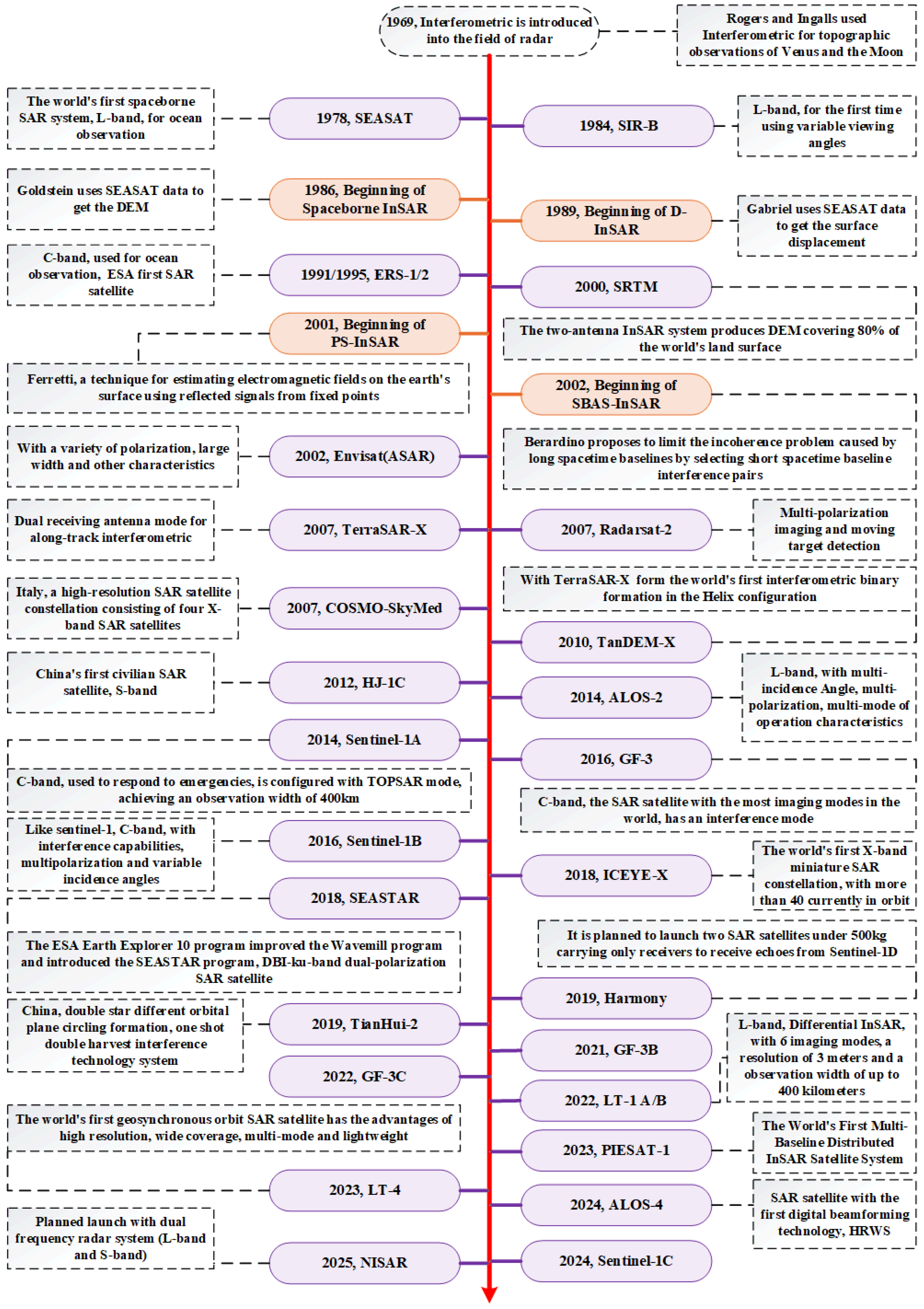
Figure 2.
Spaceborne SAR system.
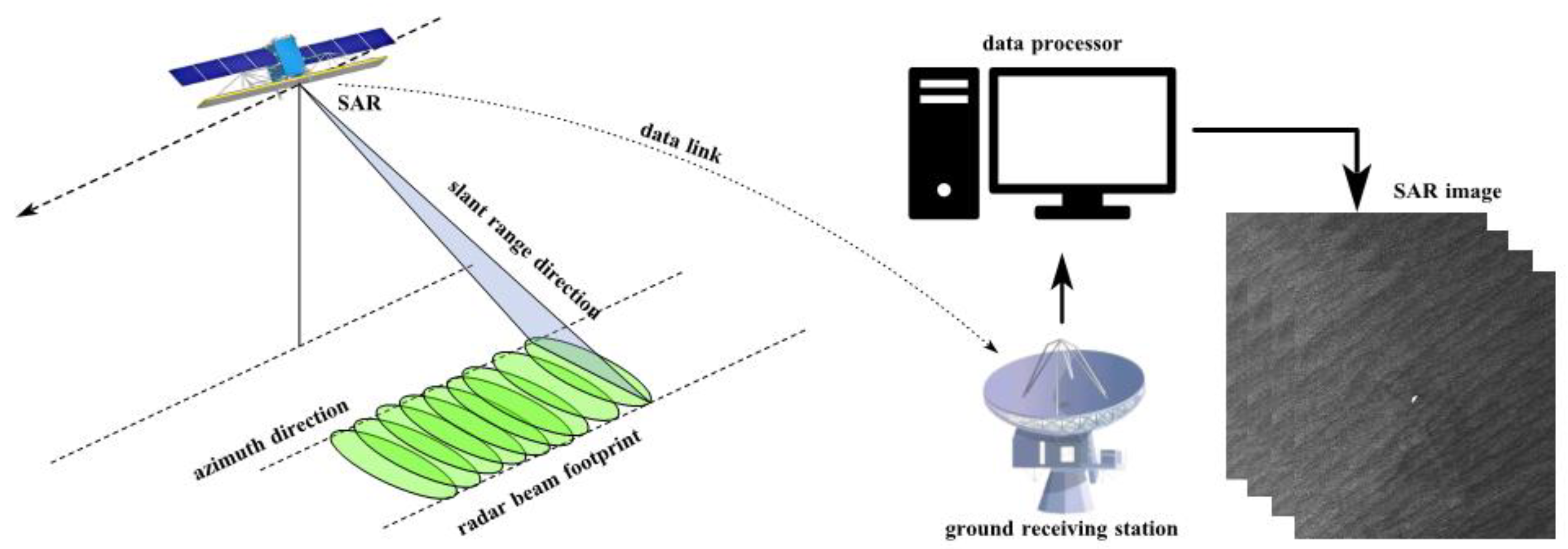
Figure 3.
Flow for the measurement of surface elevation change by D-InSAR.[4].
Figure 3.
Flow for the measurement of surface elevation change by D-InSAR.[4].
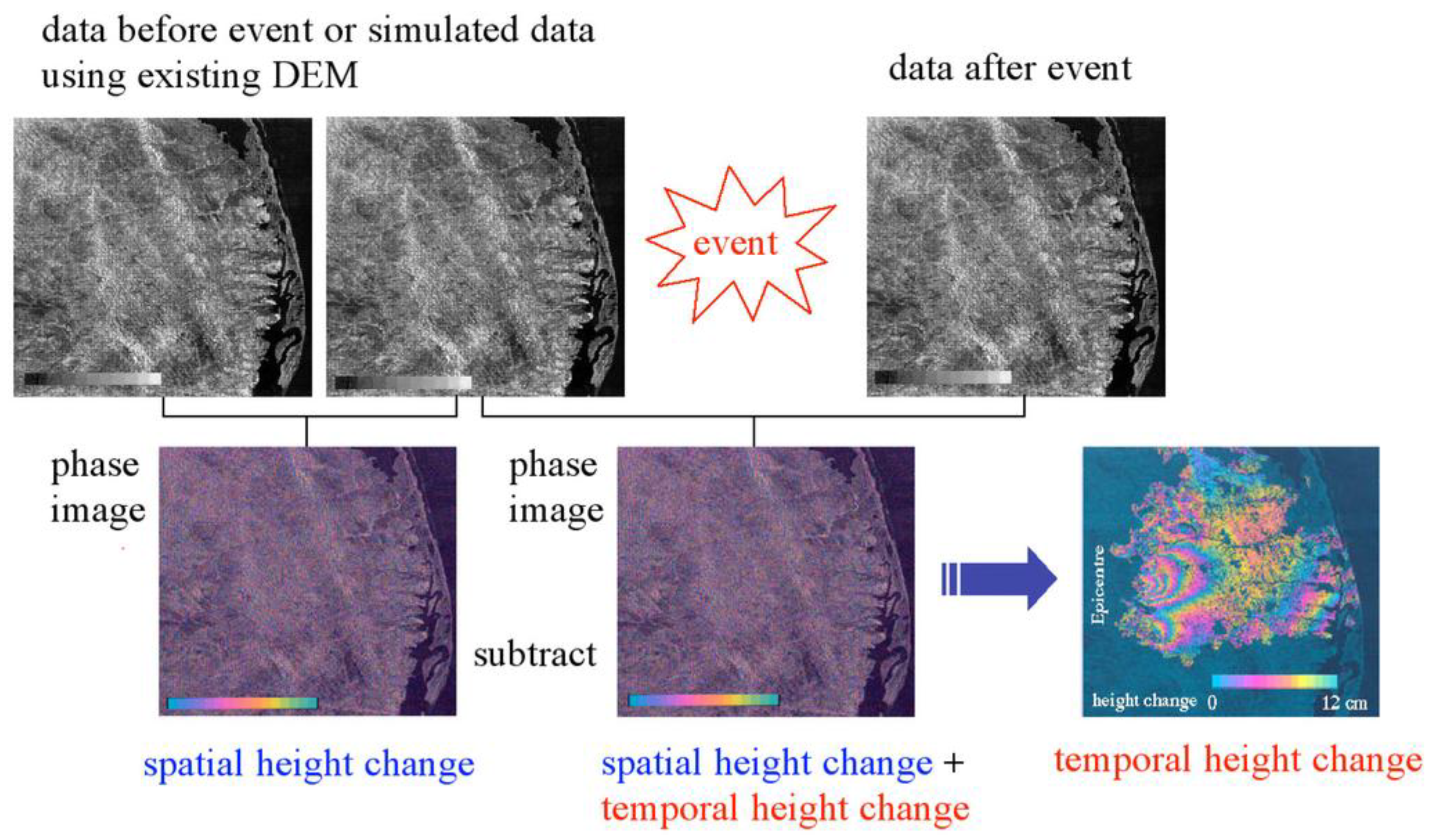
Figure 4.
1999 Türkiye Mw7.1 Izmit earthquake by D-InSAR.[23].
Figure 4.
1999 Türkiye Mw7.1 Izmit earthquake by D-InSAR.[23].
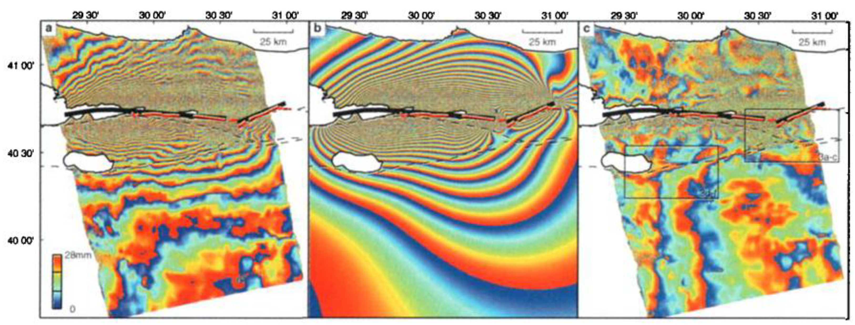
Figure 5.
1992~2000 Chile earthquakes by D-InSAR.[28].
Figure 5.
1992~2000 Chile earthquakes by D-InSAR.[28].
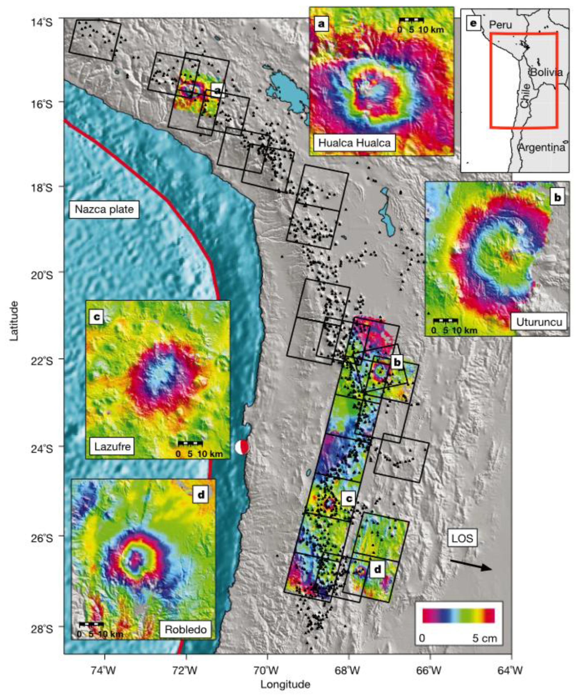
Figure 6.
2003 Bam Mw6.8 earthquake and deformation by D-InSAR.[29].
Figure 6.
2003 Bam Mw6.8 earthquake and deformation by D-InSAR.[29].
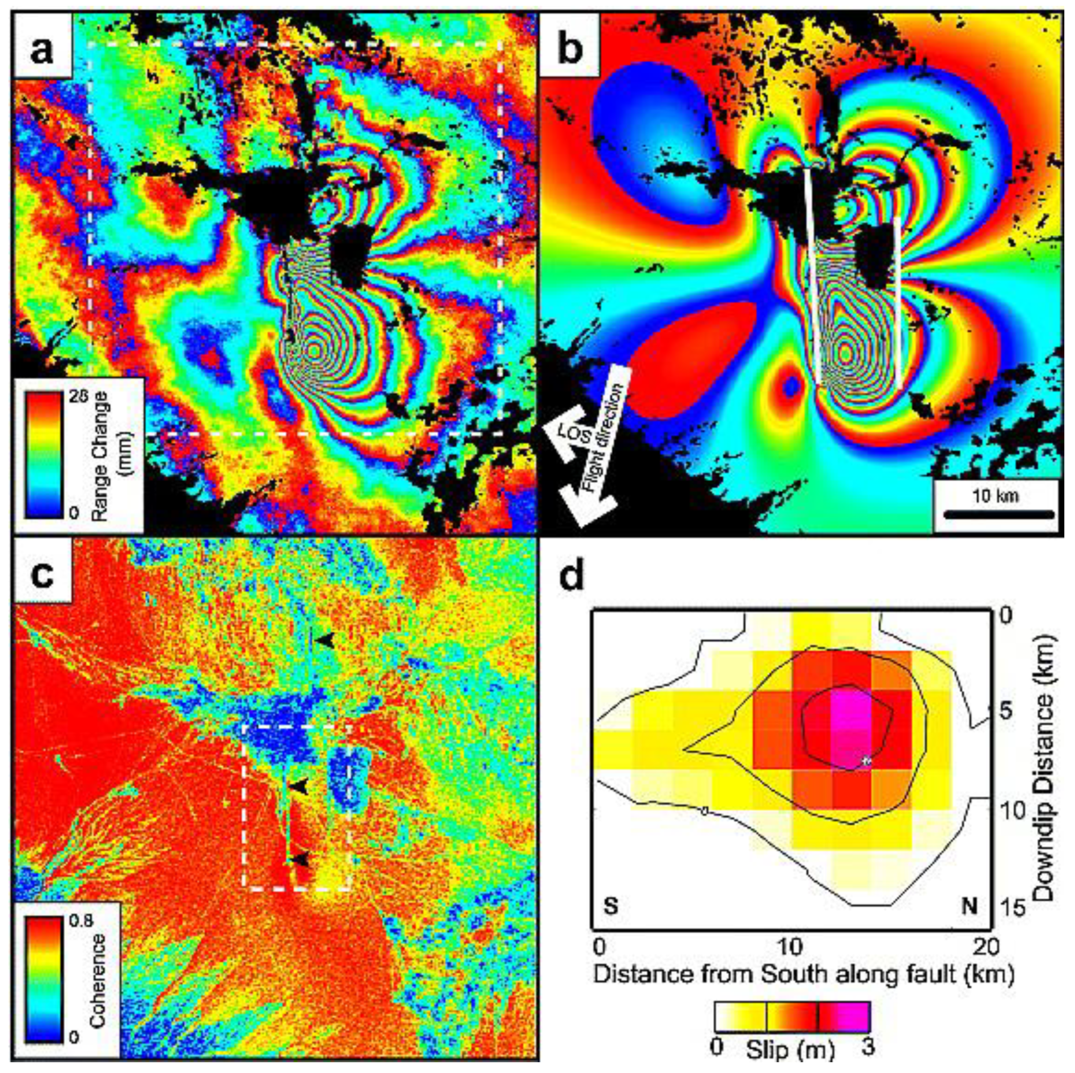
Figure 9.
Comparison of wrapped multi-looked interferograms from (top) conventional InSAR and (bottom) the wrapped phase of individual PS, corrected for DEM error [41].
Figure 9.
Comparison of wrapped multi-looked interferograms from (top) conventional InSAR and (bottom) the wrapped phase of individual PS, corrected for DEM error [41].
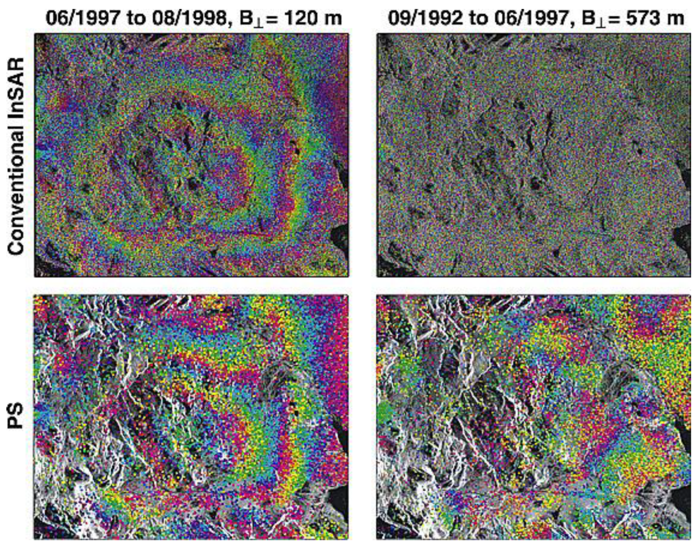
Figure 11.
Geometry of repeat-pass. (a) CT (Cross-Track)-InSAR; (b) AT (Along-Track)-InSAR.
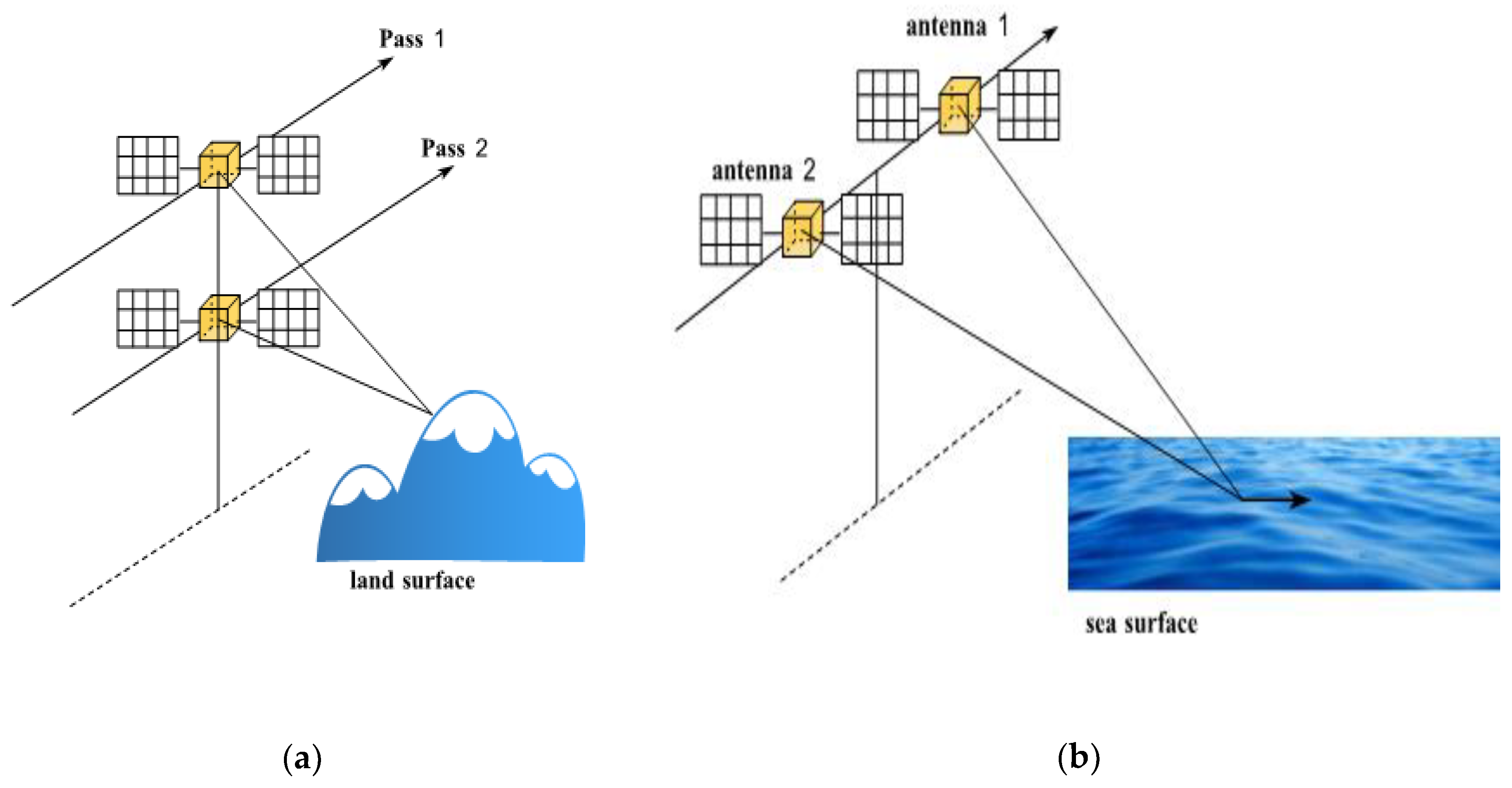
Figure 12.
Flow of CT-InSAR DEM generation [4].
Figure 12.
Flow of CT-InSAR DEM generation [4].
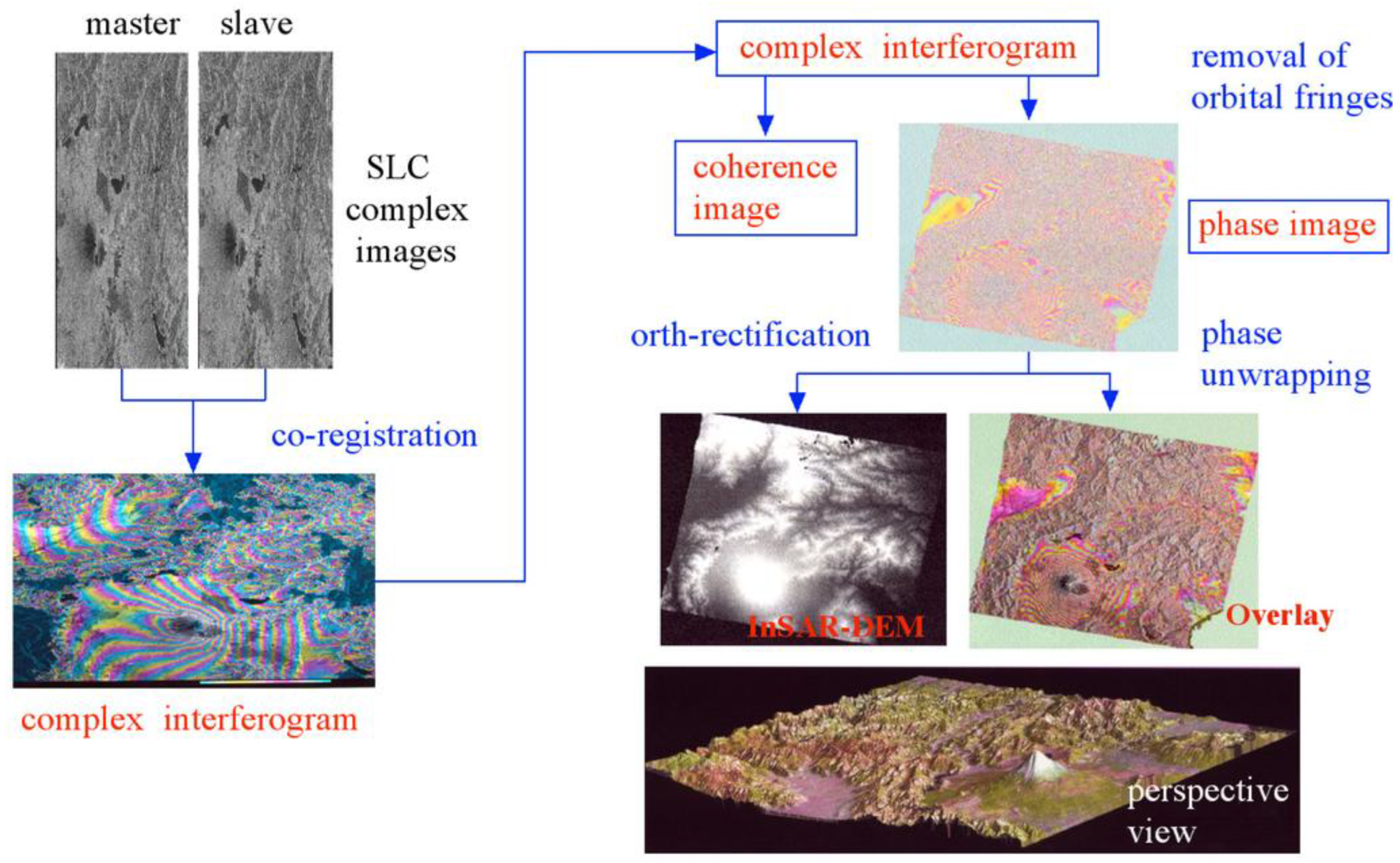
Figure 13.
Yueyang County, Hunan Province DSM generation [63].
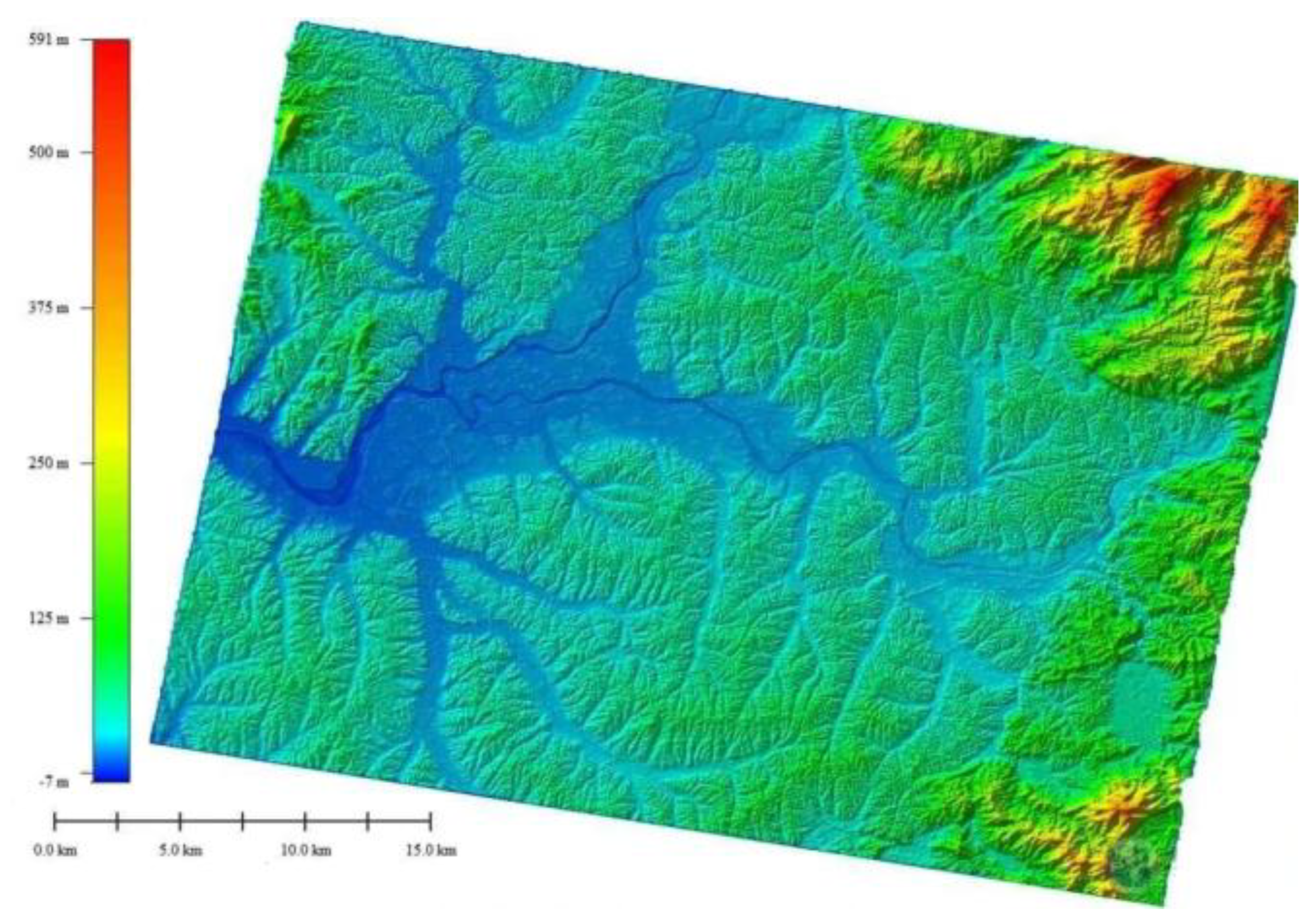
Figure 16.
The observation geometry of the DBI method.
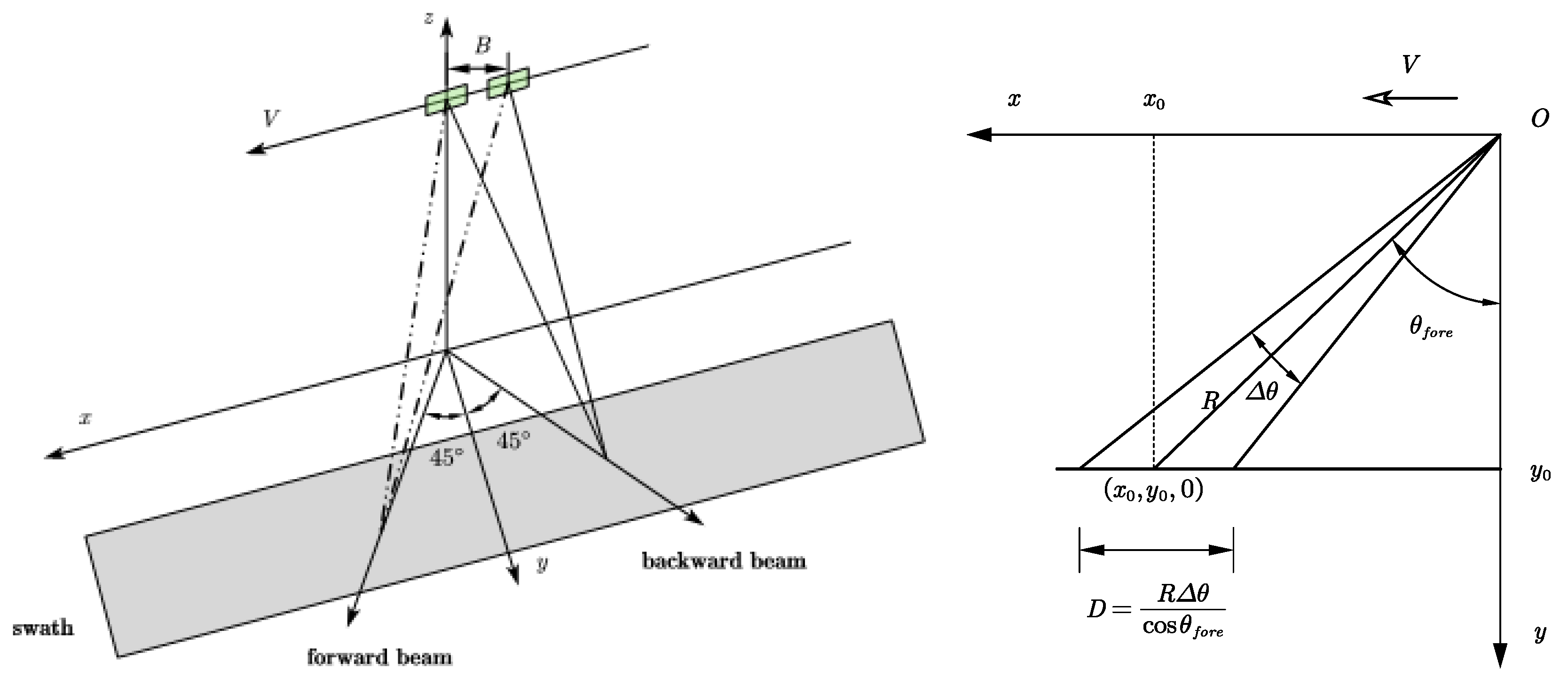
Figure 17.
TSX and TDX AT-InSAR system.
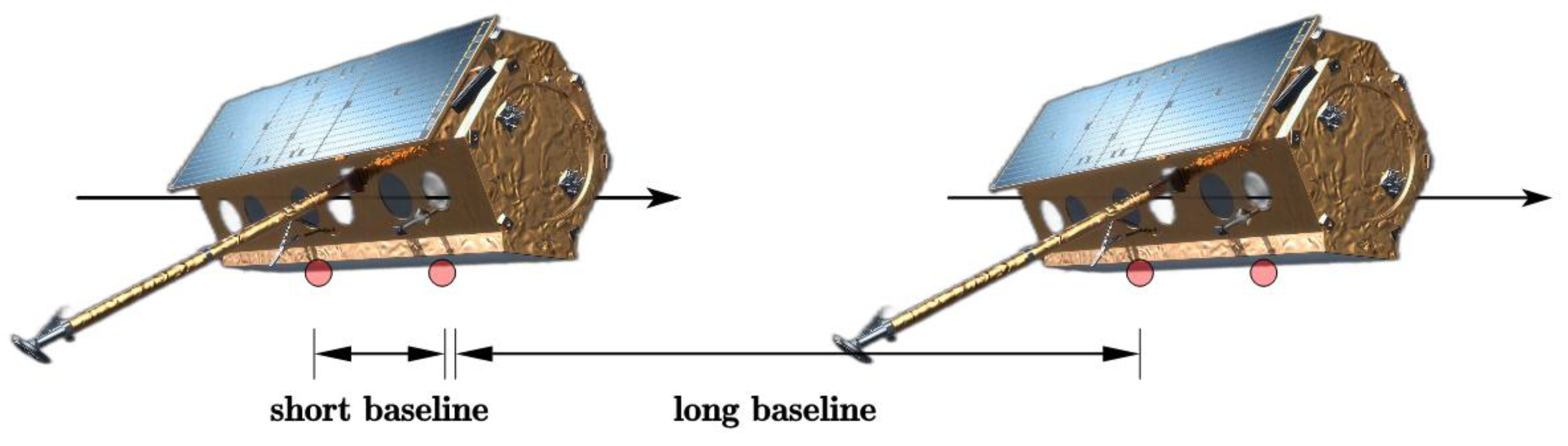
Figure 19.
Norway's Svalbard islands are covered by ice caps [88].
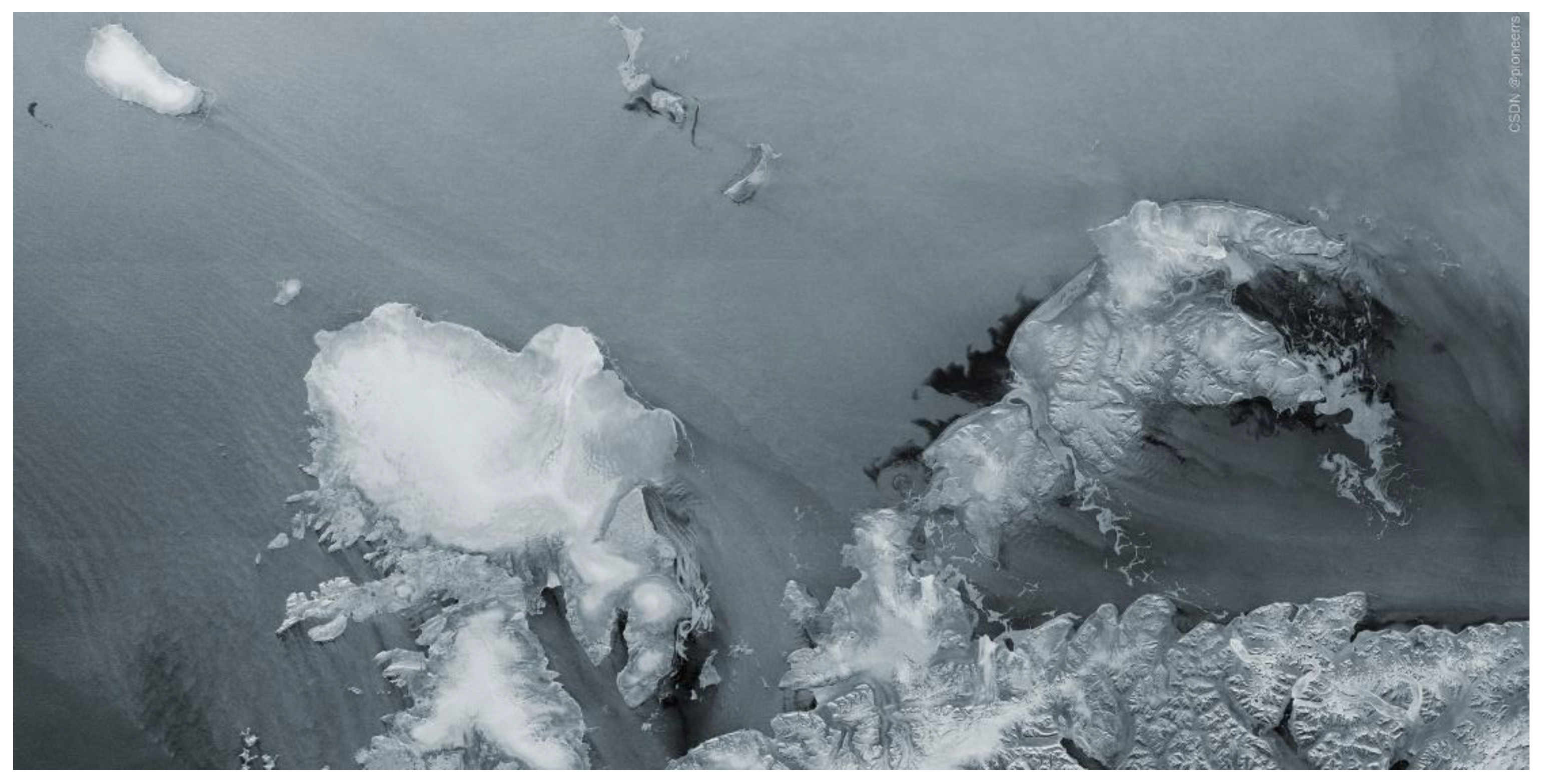
Figure 25.
DSM data in Fly-around mode.
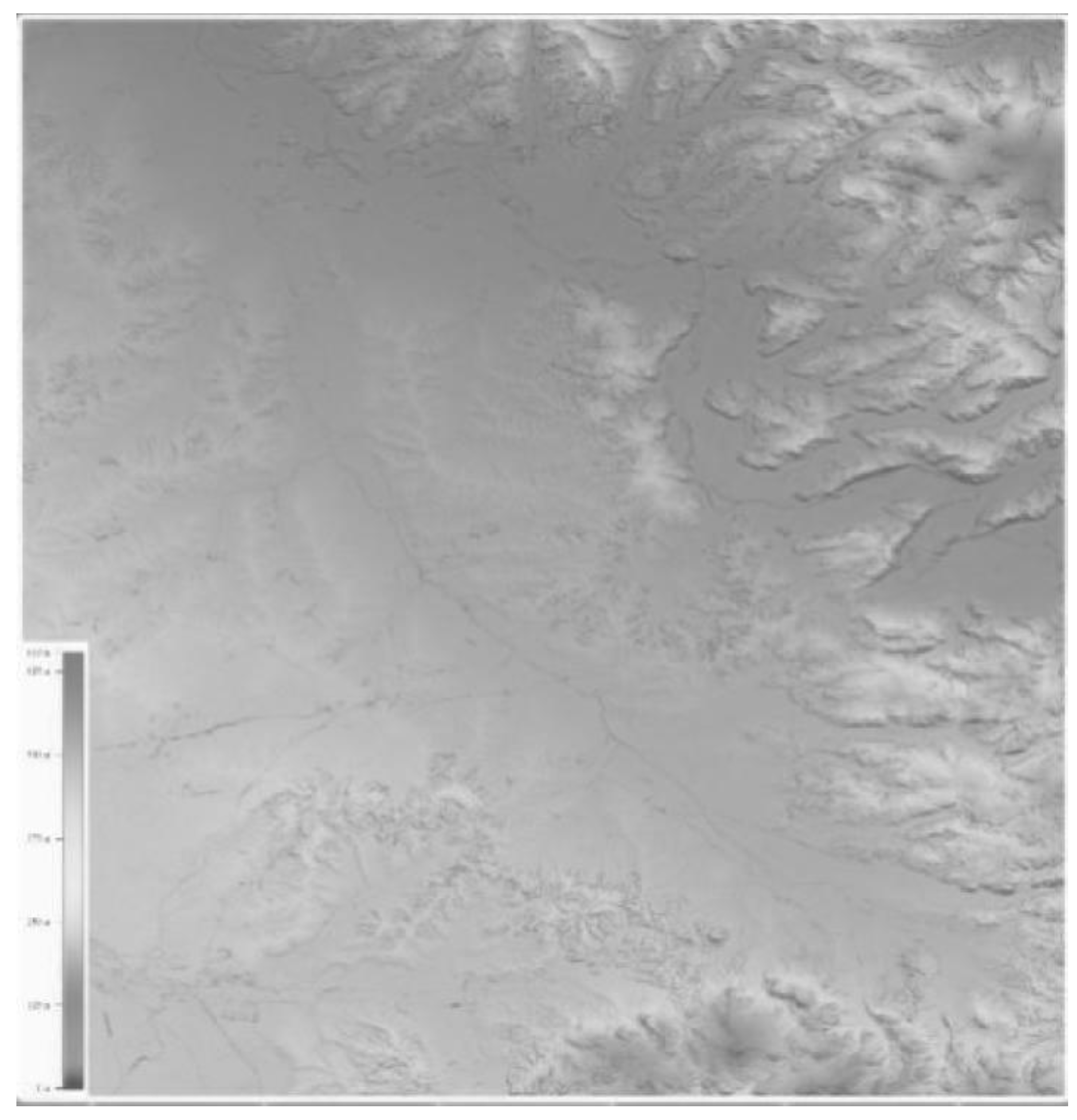

Table 1.
Classification of typical surface deformation phenomena[19].
Table 1.
Classification of typical surface deformation phenomena[19].
| Geophysical phenomenon | Process classification | Spatial scale/km | Deformation scale/mm | |||
|---|---|---|---|---|---|---|
| Instantaneous | Slow | Reversible | Irreversible | |||
| Active volcano rises or sinks | — | ✓ | ✓ | — | < 20 | < 5 |
| Volcanic eruption | ✓ | — | — | ✓ | < 20 | > 50 |
| Earthquake coseismic deformation | ✓ | — | — | ✓ | 50~100 | > 50 |
| Deformation before and after earthquake | — | ✓ | — | ✓ | 50~100 | < 5 |
| Crustal fault movement | — | ✓ | — | ✓ | > 20 | < 5 |
| Surface settlement | — | ✓ | — | ✓ | 0.5~20 | 1~20/a |
| Mining subsidence | ✓ | — | — | ✓ | 0.1~10 | 1~100/d |
| Landslide (foreboding) | — | ✓ | — | ✓ | 1~20 | 1 |
| Landslide (Eruption) | ✓ | — | — | ✓ | 1~20 | > 1000 |
Table 2.
This is a table. Tables should be placed in the main text near to the first time they are cited.
Table 2.
This is a table. Tables should be placed in the main text near to the first time they are cited.
| Measurement | Precision level | GNSS | D-InSAR |
|---|---|---|---|
| Spatial coverage | Discrete point | Discrete point | Surface covering |
| Accuracy | mm | mm | mm |
| Periodic velocity | Long and slow | Short and fast | Short and fast |
| Operating condition | According to the weather | All-weather | All-weather |
| Cost | High | higher | low |
Table 3.
Comparison of InSAR and other DEM acquisition techniques.
| DEM acquisition technique | Coverage | DEM accuracy |
|---|---|---|
| Ground | Local, large scale mapping range | 0.01~0.1m |
| Airborne photogrammetry | Region | 0.1~1m |
| Airborne lidar | Region | 0.5~2m |
| InSAR | Regional to global | 1~20m |
| Shadow mapping | Regional to global | Slope<=2°,22m |
| Stereo mapping | Region | 10~100m |
Table 4.
Comparison of Digital Terrain Elevation Data (DTED-2) and High Resolution Terrain Information (HRTI-3) specifications [4].
Table 4.
Comparison of Digital Terrain Elevation Data (DTED-2) and High Resolution Terrain Information (HRTI-3) specifications [4].
| Requirement | Specification | DTED-2 | HRTI-3 |
|---|---|---|---|
| Relative vertical accuracy | 90% linear point-to-point | 12 m (slope<20%) | 2 m (slope<20%) |
| error over a 1° × 1° cell | 15 m (slope>20%) | 4 m (slope>20%) | |
| Absolute vertical accuracy | 90% linear error | 18 m | 10 m |
| Relative horizontal | 90% circular error | 15 m | 3 m |
| Horizontal accuracy | 90% circular error | 23 m | 10 m |
| Spatial resolution | independent pixels | 30 m (1 arc sec at equator) | 12 m (0.4 arc sec at equator) |
Disclaimer/Publisher’s Note: The statements, opinions and data contained in all publications are solely those of the individual author(s) and contributor(s) and not of MDPI and/or the editor(s). MDPI and/or the editor(s) disclaim responsibility for any injury to people or property resulting from any ideas, methods, instructions or products referred to in the content. |
© 2025 by the authors. Licensee MDPI, Basel, Switzerland. This article is an open access article distributed under the terms and conditions of the Creative Commons Attribution (CC BY) license (http://creativecommons.org/licenses/by/4.0/).
Copyright: This open access article is published under a Creative Commons CC BY 4.0 license, which permit the free download, distribution, and reuse, provided that the author and preprint are cited in any reuse.


