Submitted:
03 June 2025
Posted:
05 June 2025
You are already at the latest version
Abstract
.Sulfide are frequently met in natural mineral water and in different waste water streams. The consequent water treatment or utilization and strongly impeded by this fact. The sulfide removal or at least reduction can be accomplished in different ways but there is one straightforward method. It consists in capturing sulfide on carbon-based sorbent with the consequent sorbent regeneration producing electricity in a liquid fuel cell mode. Hence, there is multiple effect of sulfide removal and utilization as energy combined with water pre-treatment for various purposes.
The present study demonstrates this idea for the case of sulfide containing mineral waters and waste streams from alcohol and beverage manufacturing to be used for biogas production.
The experiments were made in a liquid phase fuel cell. The electrode compartments were separated by anion-exchange membrane. Electroconductive charcoal, produced by pyrolysis of sunflower seed husks and doped by zinc oxide was used as sorbent and electrode.
The yield of biogas produced from vinasse was increased up to four times for treated substrate compared to the reference case.
The experiments of treatment of natural water for sulfide removal by this method shows sustainable performance of the sorbent for up to twelve consecutive runs.
Keywords:
sulfide removal
; chemo-sorption
; biogas production
; fuel cell application
1. Introduction
Hydrogen sulfide is frequently met in nature, as a component of mineral waters, as a by-product of organic matter biodegradation and as a waste product of various industrial applications, like oil processing, mining, tanning, pulp and paper processing, etc. The presence of hydrogen sulfide in natural water and in waste streams in industry in undesirable because of its high toxicity and corrosivity for the metal elements of industrial equipment. Being very toxic, it is harmful for environment even at very low concentrations. One enormous source of hydrogen sulfide exists in the deep waters of the Black Sea [1]. The latter fact and the very large amounts of polluted air and water to be treated make its removal very costly. There are different methods for its removal, like chemical ones (oxidation, adsorption. absorption, sedimentation) [2,3,4] physical ones (membrane separation, condensation, ion exchange) and biological methods, like biofiltration, where hydrogen sulfide is oxidized to sulfate by thiobacteria [5].
Among the chemical methods, oxidation and absorption seem expensive, because of the huge industrial streams to be processed. The same applies to the sedimentation as sulfide of heavy metals because of their adverse effect on environment and human health.
There is another possibility to treat waste streams at low concentrations of hydrogen sulfide. It consisted in the use of hydrogen (or sulfide at all) as a reductor in fuel cells. Similar attempts were made for waste gas stream [6] where hydrogen sulfide was oxidized to elemental sulfur and for aqueous solutions in liquid phase fuel cell [7]. The advantages of this approach are: the processes are straightforward with involved few operations. It is energy saving because of the generation of electromotive force.
The previous hydrogen removal is required for some industrial processes, e.g. biogas production from organic waste [8]. The latter contain hydrogen sulfide being harmful for the bacterial consortium degrading the organic matter to combustible biogas and nitrogen-rich residue. It was proposed recently an integrated method for hydrogen sulfide adsorption on charcoal doped by zinc oxide [9]. The regeneration of the adsorbent was accomplished in a fuel cell mode in aqueous medium. The electroconductive charcoal served as anode and the adsorbed pollutant as zinc sulfide was oxidized and washed out as sulfate or sulfite.
The principal sketch of the process is shown in Figure 1.
2. Materials and Methods
1.1. Fuel Cell Experiments
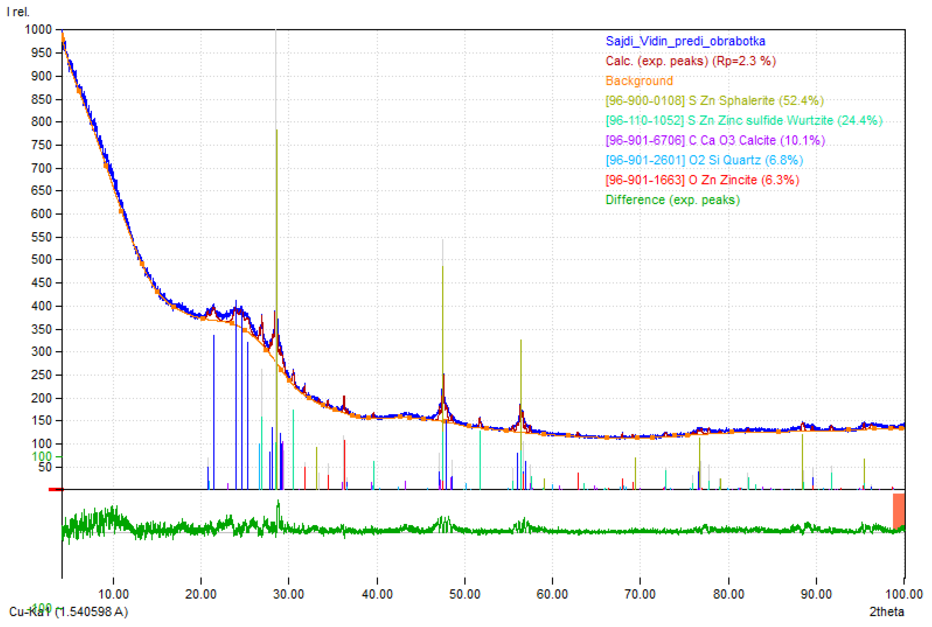
Experiments were carried out in continuous mode in a rectangular fuel cell, shown in Figure 2. The substrate solution was fed into the anodic space by with a flow rate of 0.02 or 0.4 l/h. The anodic space was packed by sorbent particles of charcoal doped by zinc oxide. The sorbent was prepared by pyrolysis of residual soot from tire production soaked with zinc acetate. Its XRD-diagram is shown in Figure 3. The sorbent particles were of 0.1cm average size. The prepared chemo-sorbent is electro-conductive and thus it enlarges the apparent anode area. The fuel cell shown in Figure 2 has a cross section of 100 sq/cm. The electrodes are 10 ×10 cm square-shaped plates of sintered graphite (a Cometech OOD production).
Oxygen was introduced by direct aeration passing air through the sodium chloride solution filling the cathode space with a flow rate of 500 L/h or by passing through the fuel cells a solution of supporting electrolyte previously saturated by oxygen.
The void operating volume for the packed anode space was 50 mL For the cathode one it was 50 mL too.
The fuel cell compartments were separated by anion-exchange membrane (a Selemion production, Japan). The first step of the experiments was continuous saturation of the sorbent in the anode space by sulfide contained in the substrate solutions at open circuit. During the saturation the open circuit voltage (OCV) of the cell was measured. Samples from the inlet and outlet solution were taken and analyzed for sulfide. The saturation ended when the open circuit voltage remained constant for certain time, e.g. three successive measurements. The sorption capacity (wt.%) was calculated by the difference in inlet and outlet concentration for the used flow rate.
The second step was closed circuit process of anode oxidation of the retained sulfide to sulfate in a fuel cell mode. It was carried out in two modes: static one and continuous wash-out by solution of supporting electrolyte.
Electromotive force was generated together with regeneration of the chemo-sorbent by in situ anode oxidation of the retained sulfide. The case of anode reaction involving hydroxylic anion exchange with their standard potential are presented. The main processes in the fuel cell are the following.
First step:
ZnO + S2- = ZnS - chemo-sorption
Second step:
ZnS +8OH- -8e = ZnO + SO42-, E0 = - 0.69 V,
Fuel cell anode oxidation, sorbent regeneration. There is double benefit in this process: sulfide removal and energy production.
The electrochemical cathode reaction is:
O2 + H2O +4e- = 4OH-,, E0 = 0.401 V.
The treated substrates for biogas production were residual stillage from ethanol distillation, residual vinasse from wine production and lactate containing whey. All they were taken from industrial processes in Bulgarian enterprises. A sodium chloride solution (16 g dm-3) in distilled water was used as a supporting electrolyte for the anodic compartment for wash-out in the continuous fuel cell mode. The cathode compartment was fed continuously by the same supporting electrolyte but previously aerated by air.
The organic substrates were purged by nitrogen prior to feeding the sorbent.
As supporting electrolyte sodium chloride aqueous solution during the fuel cell operations was used.
The pH of the initial solution varied between 7.3 and 12.6 depending on the sulfide concentration from 18 to 400 mg dm-3.
Twelve experiments were carried out. After each saturation, polarization curves were taken at different current densities varying the external resistance of the circuit. Then, experiments on the cell discharge through selected ohmic resistance by continuous feed by sulfide solutions were carried out. The electric current values were calculated by the Ohm’s law from the measured cell voltage and the external resistance.
The amounts of oxidized sulfide were calculated from the measured electric current according to the Faraday’s law and compared to the converted sulfide according to the analyses.
where:
i—electric current, A; •
m—mass of reacting substance, g;
t—time, s;
M—molar mass of reacting substance, g;
n—number of exchanged electrons;
F = 96,484 C mol−1 , Faraday constant
One must have in mind that sulfide can participate in various redox reactions with various products with different number of exchanged electrons. This variety becomes more diverse at higher sulfide concentrations. A short list of such reactions is shown in Table 1.
The quantitative analysis for sulfide was made photometrically with N,N-dimethyl-nphenylenediamine in the presence of Fe (III) to form methylene blue [11]. Sulfate and sulfite were qualitatively tested by the addition of barium chloride. Barium sulfite is soluble in acid medium whereas barium sulfate is not. The presence of thiosulfate was checked by the addition of ferric salts leading to purple color.Polysulfides give a colored clear solution (yellow for S2 2-) with deposition of colloidal sulfur in acid medium. All other chemicals used for analyses were of p.a. grade.
1.1. Biogas Production
The experiments for biogas production from the treated organic substrates were accomplished in lab-scale mode. Amounts of 150 ml of the treated substrates were mixed with 300 ml active ted sludge from wastewater treatment plant. The sealed flasks with the samples were kept at 320C in a water bath under static conditions. The released biogas was collected in a gas holder. The experiments continued 30-35 days. Parallel reference tests with substrates without treatment were also carried out.
3. Results
3.1. The Sorbent Composition
A XRD-diagram of the used sorbent is shown in Figure 3. The quantitative analysis of the XRD diagrams shows the following composition of the sorbent (wt.%): sphalerite (ZnS, 52.4); wurzite (ZnS, 24.4); calcite (CaCO3, 10.1); quarz (SiO2, 6.8); zincite (ZnO, 6.3). After 12 runs the amount of wurzite dropped considerably to 16.6% and zincite is slightly reduced to 5.1%. This observation can be explained by wash-out of sulfite and sulfate formed after oxidation of sulfide in the sorbent during the fuel cell operations. Sphalerite is practically not reduced. The sorption capacity remained almost constant (about 0.12 %wt.) because its active component is zincite is slightly reduced.
Figure 3.
XRD-diagram for the prepared chemo-sorbent as anode, containing zinc oxide and sulfide.
3.2. Sulfide Sorption and Removal
The experimental conditions for sulfide sorption and removal are shown in Table 2. There is no clear correlation between the substrate origin, the initial sulfide concentration and open circuit voltage. But it was found that the sulfide anions are completely captured by the sorbent.
A polarization curve for a fuel cell operating with already saturated sorbent is shown in Figure 4. The straight line means there no overpotential at low currents, nor mass transfer limitations at higher ones.
An elution curve of the sorbent in a fuel cell mode for the step of sorbent regeneration under static conditions is shown in Figure 5. It is visible that electric current reaches almost zero values, i.e. after the sorbent regeneration there is practically no more sulfide retained on the sorbent. The analytically determined amounts of sulfide after the runs under static conditions correspond to the initially introduced amounts.
The mass of the removed sulfide by electrochemical oxidation in fuel cell mode was calculated from the current yield according to the Faraday’s law, Equation (1). However, the obtained values for sulfide oxidation depend on the number of electrons exchanged on the anode, cf. Table 1. Some results are shown in Figure 6.
It is evident for the cases of vinasse and stillage as substrates, that reactions with exchange of one electron are not realistic. The more probable exchange of two electrons on the anode was confirmed by the presence of sulfite and sulfate at the end solution after the fuel cell discharge or in the exit solution, when continuous wash-out took place. More probable is the oxidation of sulfite to sulfate, cf. reaction 2, Table 1.
In the case of high initial sulfide concentrations, i.e. when whey was tested the calculated yields of oxidized sulfide were much lower than the ones determined analytically. This fact can be explained by parallel parasite reactions in the bulk giving different polysulfides as products.
3.3. Biogas Production
Comparison of the results of biogas production after sulfide removal and without it is shown in Figure 7 for the case of vinasse as substrate. It is evident that the accumulative biogas yield is more than three times higher than the reference case. That is why, it could be concluded that there is neat positive effect of the sulfide removal.
This process of sulfide removal is more advantageous compared to the ones for hydrogen sulfide removal from the already produced biogas. Those are scrubbing by water, iron hydroxide, sodium hydroxide and solid phase adsorption. All they imply treatment of the resulting sulfide containing waste which is costly and environmentally inappropriate.[12]. More suitable seems the combined solid phase adsorption with photocatalytic oxidation [13].
4. Discussion
A new and simple method for removal of hydrogen sulfide and sulfide anions from natural and industrial waters is proposed. It based on integrated processes of adsorption (or chemo-sorption) and the consequent removal of sulfide from the sorbent by oxidation in aqueous solutions to harmless sulfite and sulfate. The method is significant with the energy generated in the fuel cell enabling the supply (at least partially) the equipment with energy.
The method is demonstrated by the chemosorption of sulfide to zinc oxide embedded in charcoal as a carrier. The next step is the oxidation of the formed zinc sulfide to sulfite and sulfate to be removed from the sorbent and to restore its sorption capacity. Hence, the purified streams can be used for different applications being not toxic, nor corrosive.
The proposed method has neat advantages before the known processes of scrubbing, adsorption, sedimentation because of its simplicity and avoidance of auxiliary process of secondary waste treatment and excessive energy spending.
5. Conclusions
- A simple method for hydrogen sulfide removal from aqueous solutions is proposed. It consists in capturing sulfide anions by chemo-sorption on zinc oxide attached to carbon-based carrier with the consequent sorbent recovery in a fuel cell mode. The sulfide removal is accompanied by energy production to help the process performance. There is multiple effect of sulfide removal and utilization as energy combined with water pre-treatment for various purposes.
- In the present study the treatment of waste streams from alcohol, beverage and milk manufacturing to be used for biogas production is presented. Complete sulfide removal was attained.
- The method can be extended for treatment of sulfide containing mineral waters and waste streams enabling the use of the purified water for industrial purposes.
- The yield of biogas produced from vinasse was increased up to four times for treated substrate compared to the reference case.
Author Contributions
Conceptualization, V.B. and L.L.; methodology, V.B. L.L..; validation, S.S. and I.A.; formal analysis, V.B.; investigation, S.S, I.A.; resources, L.L.; writing—original draft preparation, V.B.; writing—review and editing, V.B.; supervision, V.B.; project administration, V.B.; funding acquisition, V.B. All authors have read and agreed to the published version of the manuscript
Funding
This research was funded by the Fund for Scientific Research, Bulgaria, grant KP-06-H67/3.
Institutional Review Board Statement
Not applicable.
Informed Consent Statement
Not applicable.
Data Availability Statement
Not applicable.
Conflicts of Interest
The authors declare no conflicts of interest.
References
- Midilli, A.; Ay, M.; Kale, A.; Nejat Veziroglu, T. A parametric investigation of hydrogen energy potential based on H2S in Black Sea deep waters. Int. J. Hydrogen Energy 2007, 32, 117–124. [CrossRef]
- Jangam, K.; Chen, Y.-Y.; Qin, L.; Fan, L.-S.; Perspectives on reactive separation and removal of hydrogen sulfide. Chem. Eng. Sci. 2021, X 1, 100105. [CrossRef]
- 8 Innovations in Hydrogen Sulfide Removal, Oil Field Team, The Oil & Gas Hub, 2024.09. 8 Innovations in Hydrogen Sulfide Removal.
- Pudi, A,; Rezae, M.; Baschetti, M.G.; Signorini, V.; Mansouri, S.S. Hydrogen sulfide capture and removal technologies: A comprehensive review of recent developments and emerging trends. Separ. Purif. Technol. 2022, 298, 121448. [CrossRef]
- Vikrant, K.; Suresh Kumar Kailasa, S.K.; Tsang, D.C.W.; Sang Soo Lee, S.S.; Kumar, P.; Giri, B.S.; Ram Sharan Singh, R.S.; Kim, K.H. Biofiltration of hydrogen sulfide: Trends and challenges, J. Cleaner Prod. 2018, 187, 131-147. [CrossRef]
- Dutta, P.K.; Rabaey, K.; Yuan, Z.; Keller, J. Spontaneous electrochemical removal of aqueous sulfide. Water Res. 2008, 42, 4965–4975. [CrossRef]
- Beschkov, V.; Razkazova-Velkova, E.; Martinov, M.; Stefanov, S. Electricity Production from Marine Water by Sulfide-Driven Fuel Cell, Appl. Sci. 2018, 8, 1926.;. [CrossRef]
- Kulkarni, M.B.; Ghanegaonkar, P.M.Hydrogen sulfide removal from biogas using chemical absorption technique in packed column reactors. Global J. Environ. Sci. Manag. 2019, 5, 155-166.. [CrossRef]
- Stefanov, S.; Uzun D.; L. Ljutzkanov, L.; V. Beschkov, V. Sulfide driven fuel cell performance enhanced by integrated chemosorption and electricity generation., Bul. Chem. Commun. 2024, 56, 379-387.
- Suhotin, A.M. Guidebook on Electrochemistry (in Russian); Himia: Leningrad, Russia, 1981.
- Rees, T.D.; Gyllenpetz, A.B.; Docherty, A.C. The determination of trace amounts of sulphide in condensed steam with N-diethyl-P-phenylenediamine. Analyst 1971, 96, 201–208. [CrossRef]
- Ghimire, A.; Gyawali, R.; Lens, P.N.L. Lohani, S.P. Technologies for removal of hydrogen sulfide (H2S) from biogas, Chapter 11 in: Emerging Technologies and Biological Systems for Biogas Upgrading, Editors: Aryal, N.; Ottosen, L.D.M.; Kofoed, M.V.W.; Pant, D. Academic Press, Cambridge, Ma. U.S.A. 2021, pp. 295-320. [CrossRef]
- Fonseca-Bermúdez, Ó.J.; Giraldo, L.; Sierra-Ramírez, R.; Giraldo, L.; Moreno-Piraján, J.C. Removal of hydrogen sulfide from biogas by adsorption and photocatalysis: a review. Environ Chem Lett. 2023, 21, 1059–1073. [CrossRef]
Figure 1.
Principle sketch of the proposed process. Phase 1 – charging the sorbent in the anode space by sulfide and feeding the bioreactor. Phase 2 – sulfide oxidation in a fuel cell mode with generation of electromotive force. The present work shows experimental results for sulfide removal from three substrates of natural origin prior to biogas production combined with the adsorbent regeneration in a fuel cell mode. Comparison of the biogas yield with and without sulfide removal is given too.
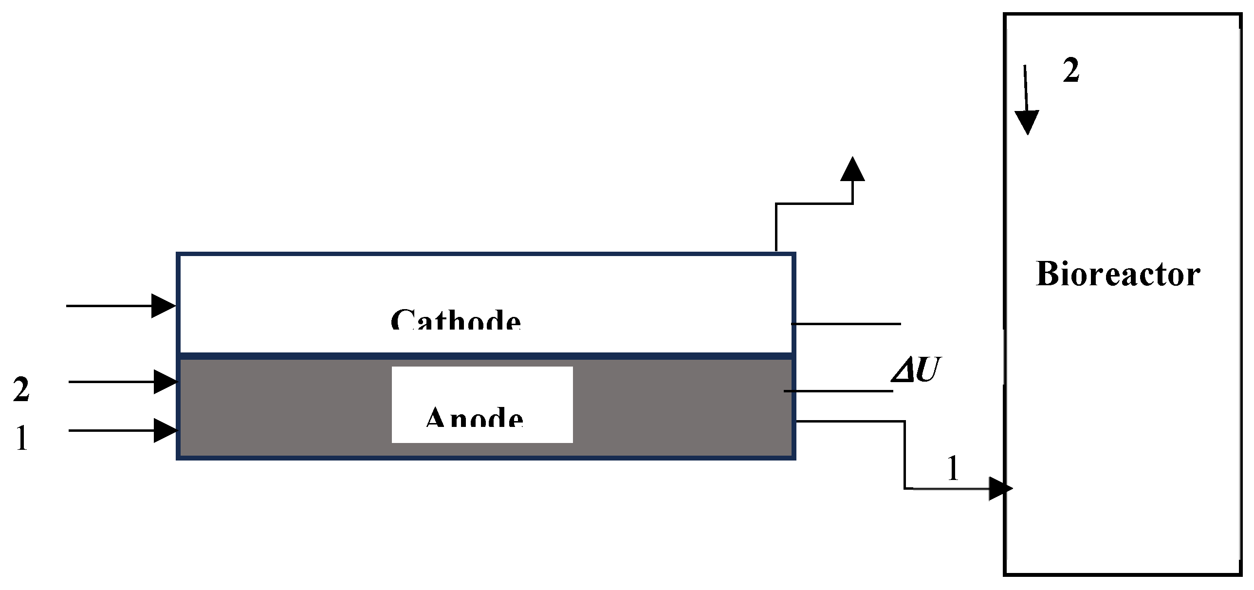
Figure 2.
Set-up of a single rectangular fuel cell with 100 sq/cm electrode and membrane area.
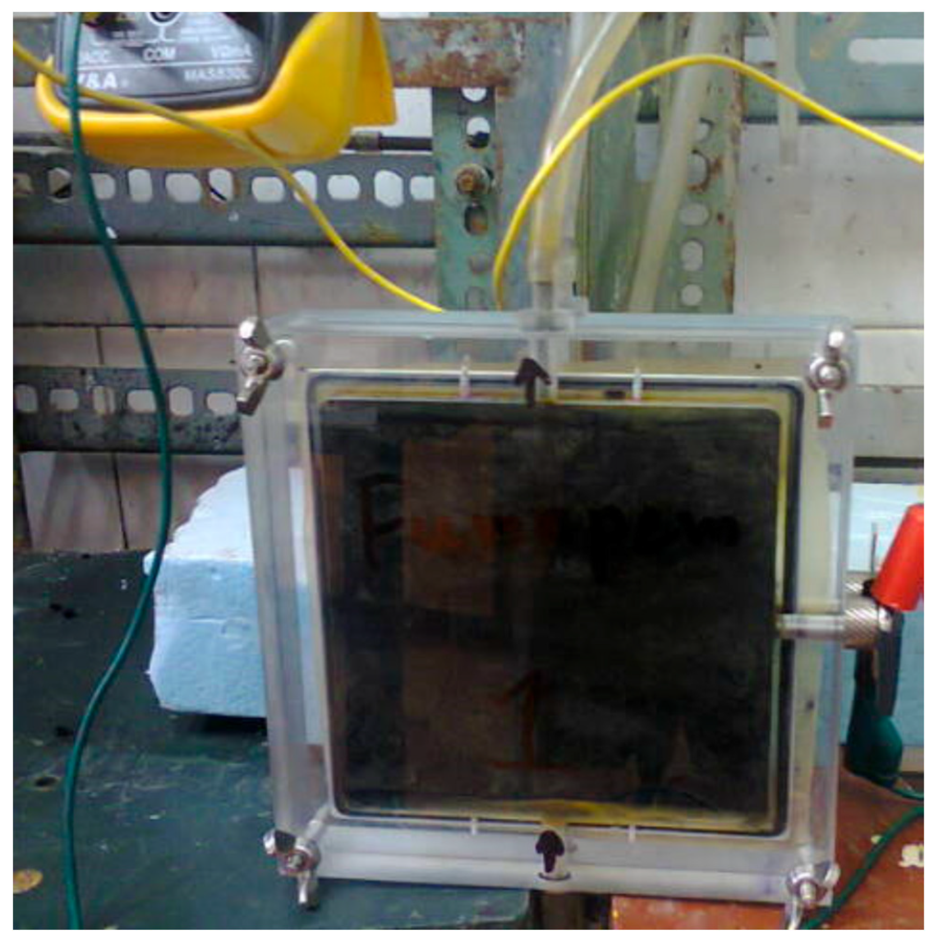
Figure 4.
Polarization curve for fuel cell saturated by stillage substrate, 79.1 mg/d-3 initial sulfide concentration.
Figure 4.
Polarization curve for fuel cell saturated by stillage substrate, 79.1 mg/d-3 initial sulfide concentration.
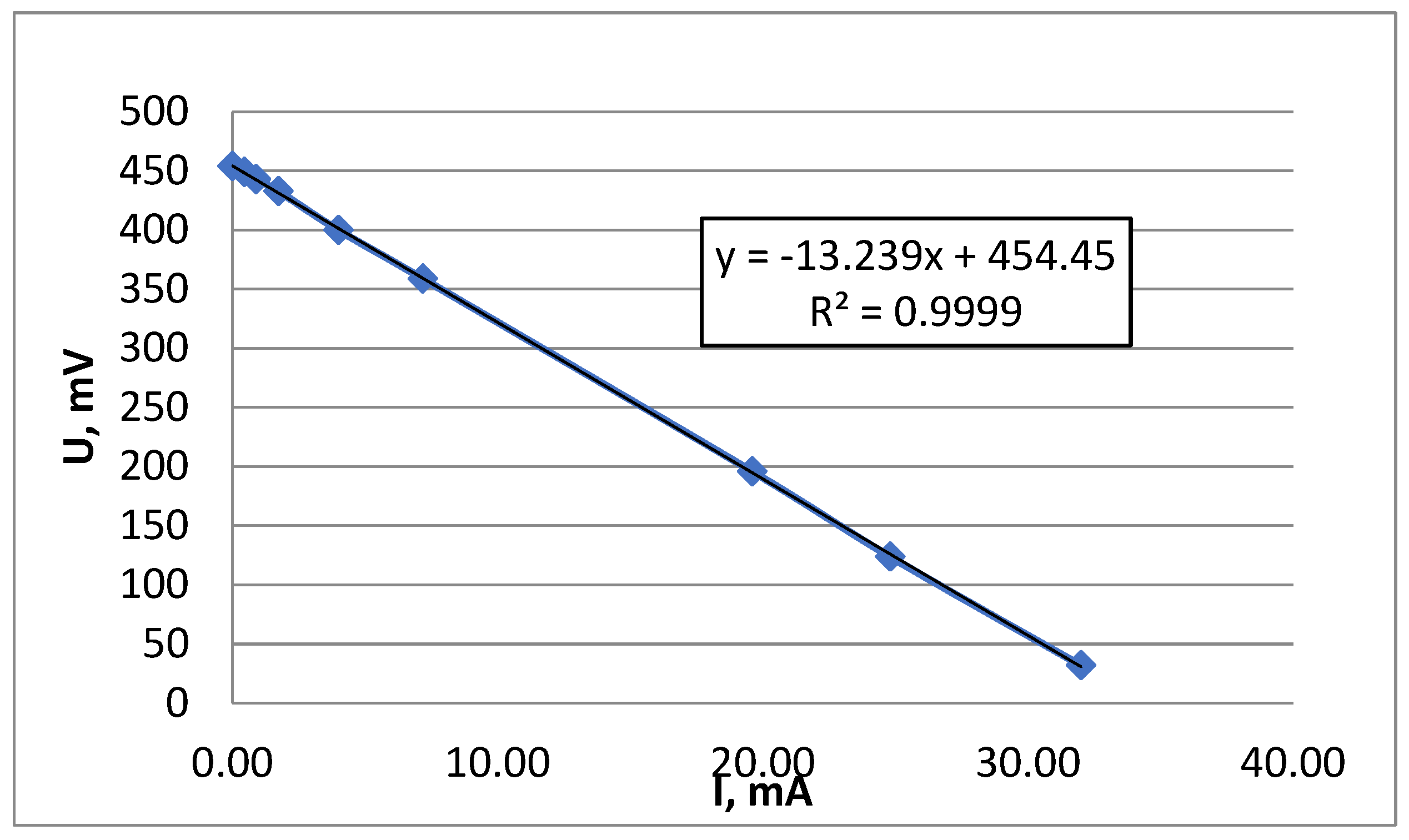
Figure 5.
Electric current during fuel cell discharge under static conditions. Stillage solution, 79.1 mg dm-3 initial sulfide concentration.
Figure 5.
Electric current during fuel cell discharge under static conditions. Stillage solution, 79.1 mg dm-3 initial sulfide concentration.

Figure 6.
Comparison of the mass yield of removed sulfide in fuel cell mode calculated according to Faraday’s law and the analytically determined ones. Processes under static conditions.
Figure 6.
Comparison of the mass yield of removed sulfide in fuel cell mode calculated according to Faraday’s law and the analytically determined ones. Processes under static conditions.

Figure 7.
Comparison of the biogas yields with and without preliminary sulfide removal for the case of vinasse (150 ml) as substrate. Addition of activated sludge (300 ml).
Figure 7.
Comparison of the biogas yields with and without preliminary sulfide removal for the case of vinasse (150 ml) as substrate. Addition of activated sludge (300 ml).
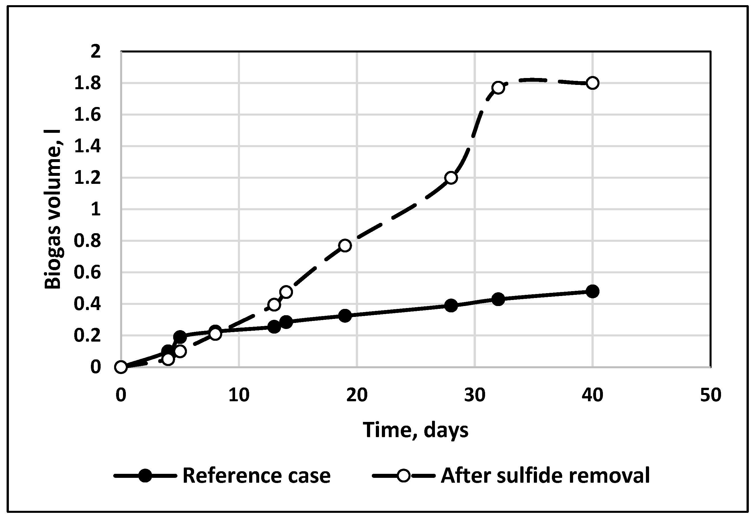

Table 1.
Short excerpt of redox reactions involving sulfide oxidation [10].
Table 1.
Short excerpt of redox reactions involving sulfide oxidation [10].
| No. | Reversible anode reaction | Number of exchanged electrons, n | Standard electrode potential, V, 25oC |
| 1 | SO3 2− + 3H2O + 6e = S2− + 6OH− | 6 | -0.91 |
| 2 | SO4 2− + H2O + 2e = SO3 2− + 2OH− | 2 | -0.66 |
| 3 | S22− + 2e = 2S2− | 1 | -0.524 |
| 4 | S + 2e = S2− | 2 | -0.480 |
| 5 | S2O3 2− + 6H+ +8e = 2S2− + 3H2O | 4 | -0.006 |
| 6 | SO4 2− + 4H2O + 8e = S2− + 8OH− | 8 | -0,693 |
Table 2.
The limit open circuit voltage determined for different organic substrates after saturation.
Table 2.
The limit open circuit voltage determined for different organic substrates after saturation.
| Substrate | Sulfide concentration, mg dm-3 | Open circuit voltage, V |
| Vinasse | 54.3 | 0.37 |
| Vinasse | 62.3 | 0.37 |
| Whey | 182 | 0.52 |
| Whey | 358 | 0.47 |
| Whey | 392 | 0.51 |
| Stillage | 18 | 0.30 |
| Stillage | 39.7 | 0.34 |
| Stillage | 79.1 | 0.45 |
Disclaimer/Publisher’s Note: The statements, opinions and data contained in all publications are solely those of the individual author(s) and contributor(s) and not of MDPI and/or the editor(s). MDPI and/or the editor(s) disclaim responsibility for any injury to people or property resulting from any ideas, methods, instructions or products referred to in the content. |
© 2025 by the authors. Licensee MDPI, Basel, Switzerland. This article is an open access article distributed under the terms and conditions of the Creative Commons Attribution (CC BY) license (http://creativecommons.org/licenses/by/4.0/).
Copyright: This open access article is published under a Creative Commons CC BY 4.0 license, which permit the free download, distribution, and reuse, provided that the author and preprint are cited in any reuse.


