
Submitted:
30 May 2025
Posted:
03 June 2025
You are already at the latest version
Abstract
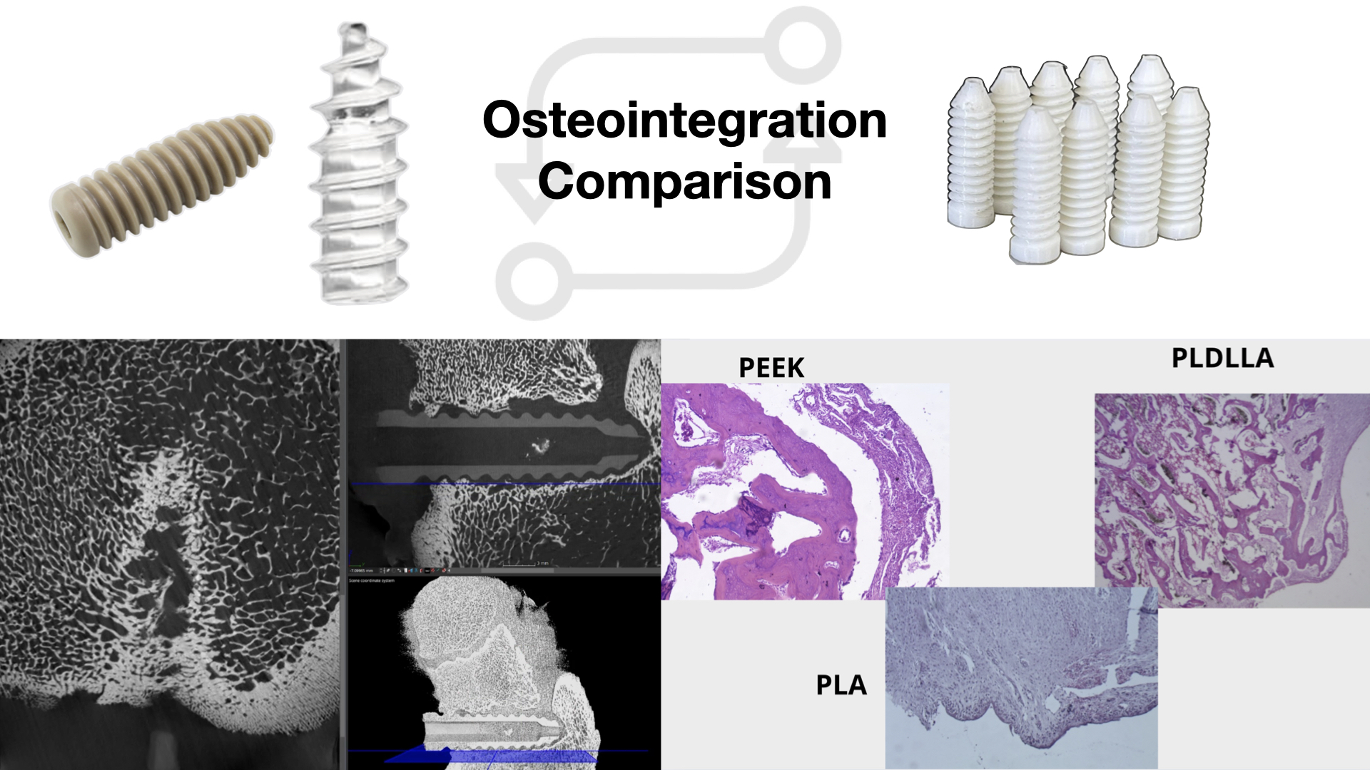
Background/Objectives: Biodegradable polymers like poly(L-lactide-co-D,L-lactide) (PLDLLA) and polyetheretherketone (PEEK) are clinically used as temporary orthopedic implants. Although polylactic acid (PLA) has comparable mechanical properties, its 3D-printed form lacks clinical validation. This study aimed to assess whether 3D-printed PLA exhibits biocompatibility, structural stability, and bone integration similar to PLDLLA and PEEK. Methods: The study consisted of in vitro and in vivo phases. In vitro, 3D-printed PLA screws were immersed in simulated body fluid (SBF) to evaluate structural integrity and degradation. In vivo, PLA, PLDLLA, and PEEK screws were implanted into porcine femurs and analysed by computed tomography and histological examination to assess osseointegration and implant stability. Results: In vitro, PLA maintained structural integrity in SBF without premature degradation. In vivo, PLA exhibited progressive bone formation and osteointegration by 3–4 months, though neovascularization was limited. PLDLLA showed direct cortical bone integration with mild inflammation, while PEEK induced fibrointegration without osteoid formation. Conclusions: 3D-printed PLA demonstrated biocompatibility and bone integration comparable to PLDLLA and a more favorable osteogenic response than PEEK. These findings support its potential as a biodegradable orthopedic implant, though further studies are needed to confirm long-term clinical safety and efficacy.
Keywords:
3D-printed
; osteointegration
; biodegradable materials
1. Introduction
Due to the continuous rise in global consumption driven by population growth and industrial demand, there is an increasing emphasis on developing advanced materials that address both functional performance and environmental sustainability [1]. Among these, polymers have become indispensable owing to their versatility and widespread use across multiple industries, including healthcare [2]. From packaging and textiles to biomedical devices and surgical sutures, synthetic polymers play a central role in modern life, particularly due to their adaptability in medical applications such as surgical implants and coatings [3].
While polymers offer remarkable versatility and have become essential across multiple sectors, their extensive use has also contributed to significant environmental concerns. Over 100 million tons of plastic are produced globally each year, a substantial portion is used for disposable packaging with a short life cycle, often ending up in landfills where decomposition can take over a century [1,4]. Considering these challenges, biodegradable polymers have emerged as a sustainable alternative, offering the potential to reduce long-term ecological impact while supporting innovation in fields such as regenerative medicine and bioengineering [5].
Biodegradable polymers can be classified into natural (collagen, chitosan, alginate) and synthetic types (polylactic acid (PLA), polycaprolactone (PCL), and poly (L-lactide-co-D, L-lactide [PLDLLA]) [6,7]. These materials are increasingly utilized in medical applications due to their tuneable degradation rates, biocompatibility, and mechanical versatility, making them ideal for temporary implants and fixation devices.
Beyond biodegradable options, certain non-resorbable polymers have also gained prominence in medical fields due to their exceptional mechanical and structural properties. One notable example is polyether ether ketone (PEEK) a high-performance thermoplastic known for its biocompatibility, strength, and radiolucency [8]. Though it does not degrade within the body, PEEK is commonly used in applications where long-term stability and durability are required, such as spinal cages, craniofacial implants and orthopaedic fixation devices [9].
In the field of orthopaedics, the use of bioresorbable materials for bone fixation has become a widely researched topic because of their potential to eliminate the need for hardware removal and reduce long-term complications associated with permanent implants [10]. Traditional metallic devices, while offering excellent mechanical strength, often require secondary surgical removal [11], which introduces additional risks such as stress shielding and disruption of natural bone remodelling. In contrast, bioresorbable materials like PLDLLA are designed to degrade gradually within the body, supporting bone healing and promoting natural bone remodelling without the need for secondary interventions [12].
In addition to these bioresorbable materials, non-degradable polymers, such as polyether ether ketone (PEEK), have also gained significant attention in orthopaedic applications. Unlike resorbable materials, PEEK remains stable within the body, providing consistent support for bone healing over extended periods [8].
Another material of interest is polylactic acid (PLA) which has emerged as a promising biodegradable polymer with excellent physical and mechanical properties. It can be processed into rigid or flexible forms and is gradually reabsorbed by the body, making it especially attractive for medical use [13]. Traditionally, PLA has been successfully used in applications such as surgical sutures, orthodontics, and orthopaedics [12]. More recently, its versatility has extended to the field of 3D printing, where it is being explored for the fabrication of custom bone fixation devices [14]. This emerging approach allows for the creation of patient specific implants, opening new possibilities for personalized orthopaedic treatments.
Despite these significant advancements in orthopaedic implants in recent years, which have led to the development of materials with biocompatible, biodegradable, and high mechanical strength properties, there remains limited research on the application of 3D printed PLA for bone fixation [15]. Materials such as PLDLLA and PEEK have been widely used in humans for bone screws, demonstrating adequate osteointegration and tissue compatibility [10]. However, the use of 3D printed PLA in humans for this purpose has not been fully explored, and its osteointegration capacity and biological behaviour are still not well understood.
This study compares the histological and imaging results of three materials: PLDLLA, PEEK, and 3D printed PLA, after implantation in piglets, aiming to assess whether PLA exhibits similar osteointegration and tissue response as PLDLLA and PEEK. The lack of previous evidence regarding the use of 3D printed PLA for orthopaedic implants justifies the need for this investigation, with the goal of evaluating its viability as an alternative material for bone fixation.
Therefore, this study aimed to evaluate the osteointegration and biocompatibility of bone screws made from 3D printed PLA, and to compare their biological performance to that of clinically established materials such as PEEK and PLDLLA, using a porcine model. To achieve this, the study involved a 12-month in vivo assessment encompassing preoperative, operative and postoperative phases. Immune responses were monitored, imaging studies were conducted to assess osteointegration, and the mechanical performance of each material was comparatively analysed.
With the continuous advancement of technology, the healthcare sector is increasingly incorporating innovative solutions aimed at improving the quality and efficiency of patient care. In the field of orthopaedics and traumatology, materials such as PEEK and PLDLLA have demonstrated favourable clinical outcomes and are typically manufactured through injection moulding- a technique in which thermoplastic pellets are meted an injected into precision moulds to produce devices such as orthopaedic screws [16]. While effective, this method is limited by the high cost of production, the need for specialized equipment, and reduced flexibility in customizing implants to patient-specific anatomy.
In contrast, the emergence of 3D printing introduces a transformative approach that enables the fabrication of personalized, anatomically tailored implants using biodegradable materials like polylactic acid (PLA) [17]. This technology not only allows for faster prototyping and lower production costs but also expands access to custom orthopaedic solutions in low resource settings [14]. Evaluating the biological behaviour and mechanical performance of 3D printed PLA is therefore essential to determine its potential as a viable and accessible alternative to traditionally manufactured in clinical orthopaedic practice.
To address this knowledge gap and evaluate the potential of 3D printed PLA as a viable material for orthopaedic fixation, we designed an in vitro and in vivo experimental protocol using a porcine model.
2. Materials and Methods
This research was conducted as part of a two-year preclinical study designed to evaluate the biocompatibility, biodegradation, and osteointegration of 3D printed PLA screws as well as to compare their biological performance with clinically established materials such as PEEK and PLDLLA. The project was developed in two complementary phases, using a unified experimental approach to evaluate the performance of the materials.
The first phase of the study focused on the design, fabrication and preliminary testing of PLA bone screws. The screws were designed using 3D printing technology to create custom prototypes, which were then subjected to in vitro testing. This involved immersion in simulated body fluid at 37°C for periods ranging from 1 to 10 months, to promote biodegradation and mimic the in vivo conditions that would be encountered port-implantation. During this phase, the degradation process of the PLA screws was closely monitored, evaluating changes in mass, surface structure, and mechanical integrity over time. The results of these in vitro tests provided insights into the biodegradation kinetics of PLA under conditions simulating the human body’s internal environment. Subsequently, the PLA screws were implanted into a porcine model for in vivo evaluation. These implants were evaluated at 1, 2, 4, 5, 8, and 10-month intervals to monitor the interaction between the screws and the surrounding tissue, as well as to determine the degree of osteointegration and degradation. Explant analysis was conducted using advanced imaging techniques such as computed tomography and histopathological examination, allowing for a comprehensive evaluation of tissue response, bone growth and the overall biocompatibility of the PLA material.
The second phase of this study focused on a comparative in vivo evaluation of commercially relevant materials, PEEK and PLDLLA, implanted in a porcine model. Twelve weaned piglets, aged six weeks, were selected for the experimental protocol. Each animal received two transfer screws: one composed of PEEK inserted into the right femur and one made of PLDLLA placed in the left femur, both accompanied by autograft tissue to simulate ligament fixation.
The screws, measuring 5 mm in diameter and 15-18 mm in length, were implanted under sterile conditions. Surgical access involved a posterolateral incision approximately 3 cm long over the proximal third of the femur, followed by meticulous dissection to expose the neck and trochanter.
The animals were fasted for 12 hours prior to surgery and received a multimodal anaesthetic regimen: initial intramuscular sedation followed by intravenous general anaesthesia and analgesia to ensure comfort throughout the procedure. Postoperative care included local wound management, penicillin based antibiotic therapy (12,000,000 U for three days), and administration of analgesics.
One piglet was euthanized each month over a 12-month period using intravenous overdose of phenobarbital, following prior anaesthesia. This method complied with the Mexican standard NOM 033-SAG/ZOO-2014, to ensure a humane, stress-free, and environmentally responsible procedure.
Following euthanasia, bilateral femoral samples were collected and analysed to assess the degree of bone integration and surrounding tissue response. Evaluations included computed tomography to examine screw positioning, healing progression and integration, alongside histopathological examination using haematoxylin-eosin staining. At 4x magnification, the presence of mature bone deposition and fibrosis within the screw cavity was assessed to determine osteointegration. At 20x, additional parameters such as neovascularization, osteoid deposition and synovial metaplasia were examined. This multi-parameter analysis allowed a comprehensive understanding of the biocompatibility and osteoconductive performance of each material under physiological conditions.
3. Results
Phase 1: In vitro biodegradation analysis of PLA screws
1.1. Visual Analysis Following In-Vitro Testing
A photographic documentation of the PLA screws following the in vitro biodegradation testing is presented below. Visual comparison between the screws in their initial state (Figure 1, Figure 2, Figure 3, Figure 4, Figure 5, Figure 6, Figure 7, Figure 8, Figure 9 and Figure 10) and after 10 months of immersion in simulated body fluid (Figure 11) revealed evident morphological changes. Specifically, degradation was observed at the crests of the screw threads, where small PLA fragments were detected following prolonged exposure. These fragments were absent in the screws prior to immersion, indicating the initiation of a biodegradation process. Notably, the initial signs of this potential degradation mechanism were detectable from the fifth month of exposure onwards (Figure 6).
1.2. Weight Analysis Following In-Vitro Testing
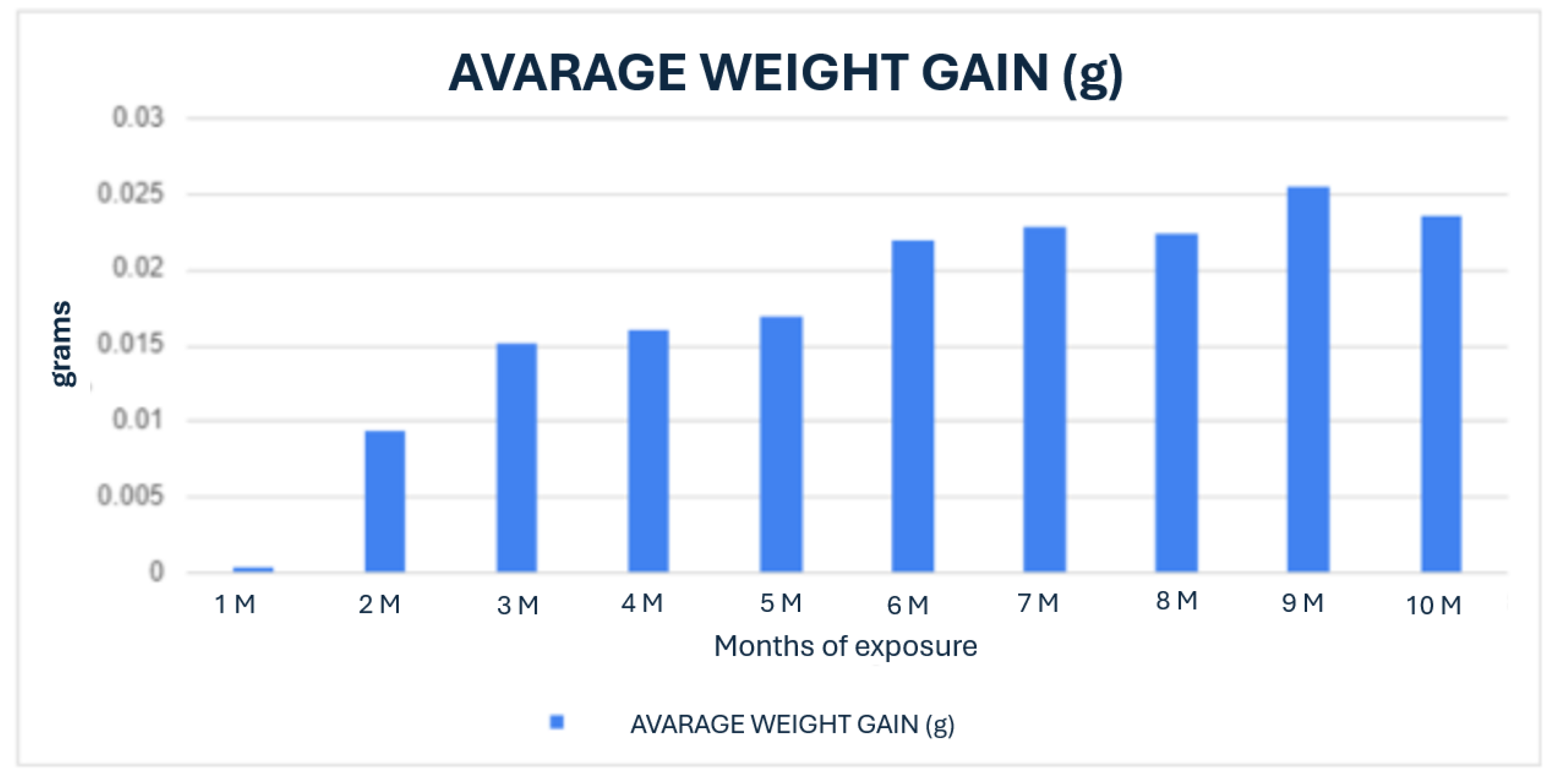
In Graph 1, the weight gain of the PLA screws resulting from their interaction with the simulated body fluid is shown, illustrating the behaviour over the 10-month monitoring period. It is observed that as the exposure time increases, there is a corresponding increase in the weight of the screws. This increase may be attributed to the absorption of the simulated body fluid solution, or the salts present within it. This absorption process could lead to changes in the physicochemical properties of the PLA screws.
Graph 1.
Average weight gain over 10 months of PLA screws exposed to simulated body fluid.
Phase 2: In vivo evaluation in porcine model
2.1. Computed Tomography Evaluation
First month.
PLA: The right femur of the first surgically treated piglet at one-month post-operation was assessed through axial slices, sagittal reconstruction, and 3D visualisation. The PLA screw implant appeared perichondral positioned and perpendicular to the longitudinal axis of the bone (Figure 12).
PEEK: The femur shows preserved bone structure, with a regular cortical course in the non-intervened regions. The growth plate is visible, correlating with the specimen’s age. A discontinuity is observed towards the ceiling of the insertion canal. A hypodense screw is identified in relation to the cortical bone, inserted into the metaphyseal region of the femur with orientation towards the femoral head. The screw appears less dense than the surrounding bone tissue, which is consistent with polymeric material. Notably, in the proximal third of the insertion site, a hypodense linear image and a discontinuity in the trabecular and cortical bone are observed, extending to the growth cartilage and the bottom of the insertion canal. In terms of biocompatibility and tissue response, there is a lack of bone coverage in the upper region of the bone channel and poor trabeculation in the lower distal third. However, no gas accumulation is observed in the surrounding soft tissues, nor are there signs of osteolysis adjacent to the implant application. The femoral geometry remains preserved, indicating a stable integration environment for the implant (Figure 13).
PLDLLA: In a 3D reconstruction view, the screw appears circumferentially, with a slight increase in bone density around it, suggesting initial bone growth that has not yet fully reached the implant. In the lateral view, slight bone growth is evident, with more development in the proximal third of the screw, indicating more pronounced consolidation in that area. Additionally, small hyperdensities within the screw suggest the presence of bone growth inside it. These findings reflect early progress in the osteogenic response and screw integration, although the consolidation process is still in its initial stages. (Figure 14)
- Second month.
PLA: A postoperative evaluation of the left femur of a porcine model was conducted at two months following implantation (Figure 15), utilizing axial cuts. Sagittal reconstruction, and 3D imaging. In the sagittal view revealed a slight increase in bone density accompanied by enhanced trabecular architecture. In the transverse slice, the PLA screw appears with a circular shape, with areas of higher density indicating mild bone growth around it. (Figure 15)
PEEK: In the 3D reconstructed presentation, the axial view shows the screw with a circular morphology, highlighting a hyperdense area in the middle third of the implant, indicative of bone growth within the screw. In the lateral view, a hyperdensity surrounding the screw is observed, reflecting bone growth that follows the shape of the insertion tunnel, accompanied by an increase in the surrounding trabecular bone. This pattern suggests an appropriate osteogenic response, with an ongoing implant integration process.(Figure 16)
PLDLLA: The left femur sample shows preserved bone integrity, with no evidence of fractures or postoperative fragmentation, and a regular cortical contour in the non-operated regions. An increase in trabecular bone density adjacent to the insertion canal is observed, with adequate coverage along the grooves of the PLDLLA screw. The screw appears hypodense compared to the cortical bone, consistent with the properties of a polymeric material, and is transversely inserted into the metaphyseal region of the femur. Its axial alignment and positioning are appropriate, with no signs of displacement or loosening. No inflammatory reactions or soft tissue collections are detected adjacent to the implant site, and no presence of gas is noted. Overall, the computed tomography study demonstrates good bone integration with no evidence of displacement or loosening. (Figure 17)
Third month.
PLA: The right femur of a surgically treated pig was examined after a three-month postoperative period using axial cuts, sagittal reconstruction, and 3D visualization. In the transverse section, a significant increase in bone trabeculation is observed, obstructing approximately 90% of the tunnel created for the insertion of the screw. In the sagittal view, an increase in circumferential hyperdensity around the screw is noted, indicating enhanced bone growth that contributes to a more stable fixation. (Figure 18)
PEEK: Postoperative evaluation of the right femur in a pig with a PEEK screw implant at three months shows the screw positioned in the proximal diaphysis of the femur. In the sagittal view, the implant appears with a circumferential shape, surrounded by a hyperdense area corresponding to cortical and trabecular bone. Trabecular formation is observed around the implant, with hypodense regions where the screw contacts the bone marrow. The surrounding bone maintains its structural architecture without signs of rarefaction or loss of density. (Figure 19)
PLDLLA: In a 3D reconstruction, the sagittal view reveals a circumferentially shaped screw. A hyperdense area is observed in the mid-third region of the screw, indicating ongoing bone growth. The lateral view confirms proper positioning of the screw within the femoral tunnel, occupying approximately 60% of the insertion tunnel. (Figure 20)
Fourth month.
PLA: Partial view of the left femur in a pig at a four-month postoperative follow-up, assessed through axial slices, sagittal reconstruction, and 3D visualization. Across all images, hyperdense areas identified, indicating bone growth into the interior of the PLA screw. Additionally, there is a partial increase in circumferential density toward the distal third of the screw, suggesting proper osseointegration and bone formation. (Figure 21)
PEEK: In the tomographic study at the fourth postoperative month, the polymer screw (PEEK) is observed following a lateralised trajectory within the medullary canal. In the sagittal and transverse projections, the femoral bone exhibits preserved structural integrity. However, suboptimal trabecular coverage is noted, particularly at the lateral and distal ends of the screw. While the proximal end shows adequate trabecular apposition, the mid to distal regions display insufficient bone integration, especially at the tip of the screw. This suggests a limited osteointegration response in those areas.
The overall bone response indicates mild biocompatibility, with sparse trabecular formation and minimal new bone coverage in the affected zones. Additionally, a few small gas bubbles are visible in the adjacent soft tissues, without signs of significant inflammatory reaction. These findings support a predominantly fibrointegrative rather than osteointegrative pattern at this stage of evaluation. (Figure 22)
PLDLLA: In sagittal slices, the screw appears with a circumferential shape, showing slight hyperdensity, which may suggest a bone growth process in that area. Surrounding the crew, a more hypodense area corresponding to the bone marrow is observed. In the lateral projection, the middle third of the screw is seen in contact with the bone marrow, while bone growth is present in the distal and proximal thirds of the implant, contributing to progressive fixation. Additionally, minimal trabecular bone growth is observed around the screw, indicating initial consolidation and integration of the implant into the surrounding bone structure. (Figure 23)
2.2. Histological Analysis
The following section presents the histological analysis of the bone tissue samples obtained after the surgical implantation of the screws. These histological sections allow for a detailed examination of bone remodelling, osteointegration, and tissue response to the implanted materials.
- First month
PLA: The PLA screw insertion site is in the articular cartilage. At this early stage, no evidence of bone growth is observed. However, a notable epithelial change is present around the screw, suggesting the development of a pseudoarthrosis. The histological section also reveals the presence of small-caliber blood vessels scattered throughout the tissue, along with signs of synovial metaplasia in the epithelium surrounding the screw. Additionally, areas of hyaline cartilage are identified.(Figure 24)
PEEK: Histological analysis reveals absence of osseointegration and presence of fibrointegration with fibrous tissue interposed between the implant and the surrounding bone. Moderate periprosthetic fibrosis is observed, characterized by the proliferation of dense connective tissue around the implant. Additionally, moderate periprosthetic inflammation is present, marked by the infiltration of immune cells, indicating an active yet controlled inflammatory response. There is prominent neovascularization and lymphoid infiltration, suggesting a sustained immune reaction. No evidence of synovial metaplasia is found. The histological sections show fibroconnective tissue located between the bone trabeculae and the implant, confirming the lack of direct bone integration. (Figure 25)
PLDLLA: In this case, histological analysis reveals absence of osseointegration, indicating that no direct union has been established between the PLDLLA implant and the surrounding bone tissue. However, fibrointegration is present, suggesting the presence of fibrous tissue at the bone-implant interface. Periprosthetic fibrosis is mild, indicating a moderate tissue response without excessive fibrous encapsulation. Neovascularization is high, reflecting significant formation of new blood vessels in the area adjacent to the implant. Focal osteoid presence is observed, indicating a limited degree of osteogenic activity at the implant interface. (Figure 26)
-Second month.
PLA: At the second postoperative month, the PLA screw is in the metaphyseal region, at the junction between the diaphysis and epiphysis of the porcine femur, as observed in the sagittal section. Histological analysis reveals poor osseointegration; however, osteoblasts are present at the bone implant interface, indicating the onset of new tissue formation. Areas of developing osteoid are also visible. Hyaline cartilage remains present, though its thickness appears reduced compared to the first postoperative month, suggesting progression in bone remodelling. At 20x magnification, no signs of periprosthetic inflammation are observed, unlike the first month there is no evidence of synovial metaplasia or neovascularization, suggesting stabilization of the local tissue response. (Figure 27)
PEEK: Histological sections revealed an absence of osteointegration; however, abundant mature connective tissue with prominent neovascularisation was observed, indicating an active attempt at vascular regeneration in the periprosthetic area. This neovascularisation may represent the body’s attempt to repair or adapt to the implant. A pronounced periprosthetic fibrosis was noted, characterized by increased collagen deposition and the formation of dense fibrous tissue surrounding the implant. A focal deposit of osteoid was identified, yet no significant new bone formation was evident, suggesting a limited osteogenic response. Mild periprosthetic inflammation was also noted, with no signs of synovial metaplasia, further supporting a low grade but chronic tissue reaction. (Figure 28)
PLDLLA: Sections revealed mature bone with minimal periprosthetic connective tissue, abundant neovascularisation, and a moderate inflammatory infiltrate. The lack of osteoid suggests that bone mineralisation occurred efficiently, without signs of delayed or abnormal matrix deposition. This, along with the presence of mature bone, indicates a more favourable osteointegrative environment compared to PEEK. The absence of synovial metaplasia reinforces the notion of a stable and well-regulated local tissue response, highlighting PLDLLA´s potential for successful integration and biofunctionality within bone tissue. (Figure 29)
- Third month.
PLA: The PLA screw was observed to be inserted epiphyseally, a location clearly visible in sagittal sections. Macroscopically, notable bone growth was identified within the interior of the screw, suggesting an active osteoconductive process. Histologically, under 4x magnification, evidence of osteointegration was apparent, indicating a favourable interaction between the biomaterial and surrounding bone tissue. At higher magnification (20x), neovascularisation appeared scarce, suggesting that while new blood vessel formation had initiated, it remained limited at this stage. A mild presence of loose connective tissue was also identified, representing a modest degree of periprosthetic fibrosis. This combination of findings suggests that the PLA screw promoted a moderate biological response, with promising signs of osteointegration but relatively limited vascular support. (Figure 30)
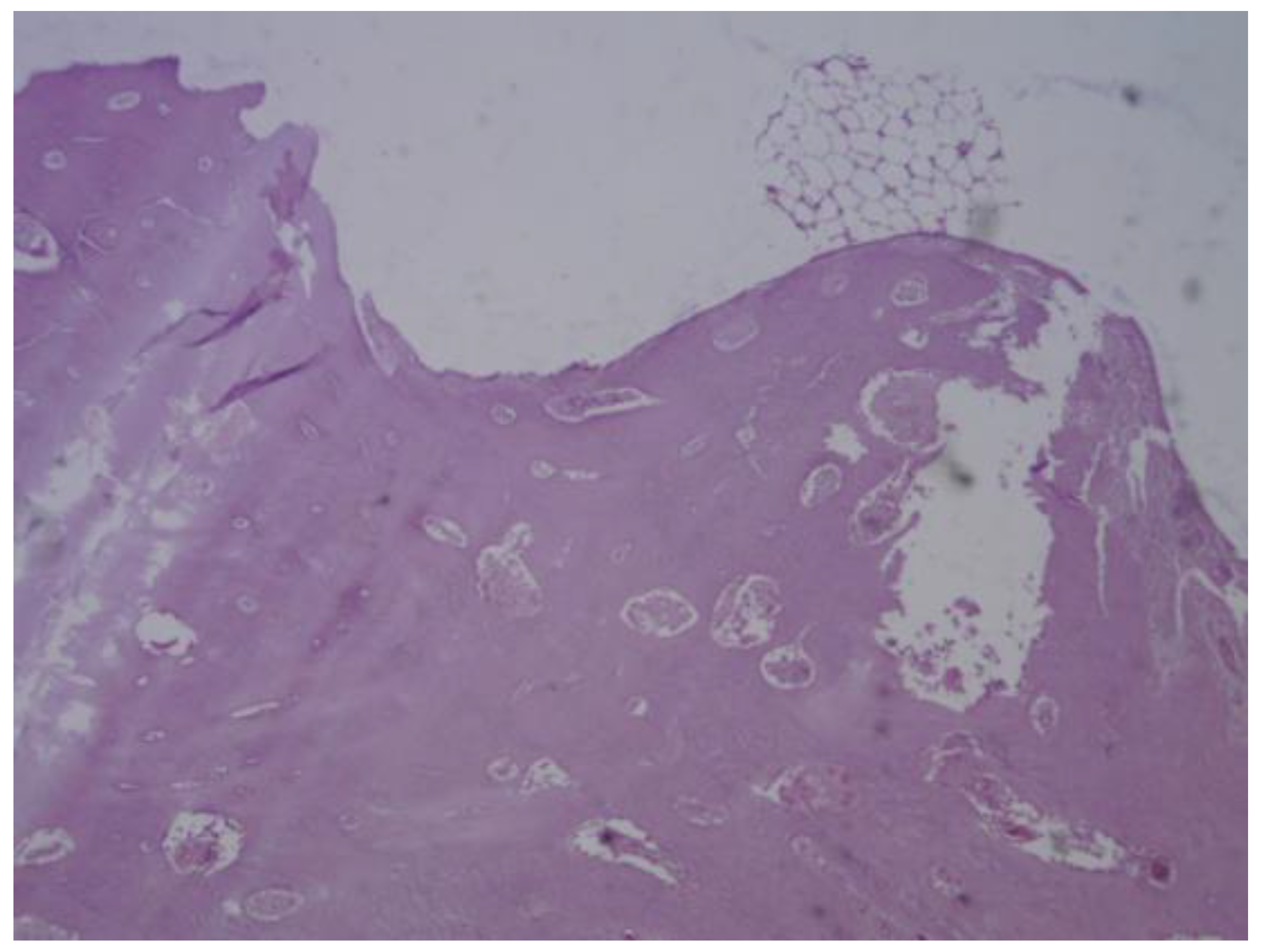
PEEK: The histological samples obtained at both the third and fourth months revealed a predominantly fibrointegrative response, characterised by the presence of a mature fibrous capsule encasing the implant. Cortical bone was observed in direct contact with the prosthesis, accompanied by areas of mature periprosthetic fibrosis, suggesting a degree of mechanical stability and material anchorage. The fibrotic reaction was moderate, with mild inflammatory infiltrates and limited neovascularisation, all of which reflect a favourable biocompatibility profile. Notably, no osteoid formation or synovial metaplasia was identified, indicating the absence of abnormal bone matrix deposition or undesirable cellular transformation. These findings suggest that PEEK elicits a stable yet primarily fibrous integration rather than a true osteointegration. (Figure 31)
- Third month.
PLA: The screw was located diaphyseal, as confirmed by its appearance in transverse histological section. Macroscopically, a distinct bone layer was observed surrounding the crew, indicative of ongoing bone remodelling. Histologically, under 20x magnification, signs of osteointegration were apparent, demonstrating direct interaction between bone tissue and the implant surface. Sparse neovascularisation was observed, suggesting limited yet active vascular development in the area. Additionally, the presence of loose connective tissue indicated a mild periprosthetic fibrotic reaction. These findings suggest that PLA supports gradual bone integration while maintaining biocompatibility and a stable inflammatory profile. (Figure 32)
PLDLLA: Histological post-implantation analysis at both the third and fourth months revealed cortical bone in close apposition to the prosthesis, accompanied by mature periprosthetic fibrosis. Effective osteointegration was evident, indicating that the material achieved direct bone contact without the interposition of fibrous tissue a key indicator of stable mechanical and biological integration. The periprosthetic fibrosis and inflammatory response were both mild, with minimal cellular infiltration, reflecting excellent biocompatibility. Scattered neovascularisation was present, supporting ongoing tissue remodelling. Importantly, there were no signs of synovial metaplasia or osteoid formation, further confirming the absence of pathological tissue reactions. Overall, these findings support a stable and successful osseous integration of the PLDLLA implant. (Figure 33)
4. Discussion
This study assessed the behaviour of bioabsorbable screws- specifically PLA, PLDLLA and PEEK- through three phases: an in vitro analysis in simulated body fluid (SBF), computed tomography imaging, and histological evaluation in a porcine model. These stages allowed us to explore the biocompatibility, bone integration and tissue response to various biomaterials used in bone fixation.
During the in vitro phase, the 3D-printed PLA screw was immersed in SBF to mimic the physiological environment of bone tissue. A progressive surface degradation of the material was observed, along with morphological changes consistent with the formation of a hydroxyapatite-like layer. This suggests potential bioactivity of the PLA, which could enhance its integration within the actual bone environment. The ability of PLA to alter its surface when exposed to SBF supports its viability as an osteoconductive biomaterial.
In the computed tomography analysis, although precise quantitative measurements were not completed, there was clear qualitative evidence of increasing periprosthetic bone density around the PLA and PLDLLA implants. This suggests a tendency toward bone integration. In contrast, the PEEK implants demonstrated less apparent bone contact, consistent with the material´s bioinert properties. These tomographic findings support the results observed in the subsequent histological phase.
Histological analysis provided a more detailed view of the osteointegration process and the tissue response to each material. PLA initially presented with pseudoarthrosis and synovial-like metaplasia but later exhibited progressive osteoid formation and direct bone-implant contact. PLDLLA demonstrated a more efficient integration, with mature bone formation from the second month, minimal fibrosis, and only mild inflammation, with no evidence of synovial metaplasia. In contrast, PEEK showed a predominantly fibrointegrative pattern, with mature fibrous capsule, limited osteogenic activity, and a persistent but low-grade inflammatory response, highlighting its limited potential for direct bone integration.
Taken together, these findings suggest that both PLA and PLDLLA exhibit bioactive properties conducive to bone integration, with PLDLLA displaying the most favourable osteointegrative and biocompatibility profile in this model. While PLA exhibited a slower response, it showed promising signs of remodelling and osteocondution. Conversely, although PEEK was well tolerated by surrounding tissues, it failed to achieve direct bone contact, limiting its applicability in situations requiring active osseointegration.
5. Conclusions
This study enabled a comprehensive evaluation of the biological and structural performance of bioabsorbable screws made from PLA, PLDLLA and PEEK, encompassing three experimental phases: in vitro testing, computed tomography imaging and histological analysis in a porcine model.
The findings suggest that both PLA and PLDLLA possess bioactive properties that promote osteointegration, with PLDLLA demonstrating a faster and more efficient response characterised by mature bone formation and minimal inflammatory reaction. Although PLA exhibited a slower integration process, it showed progressive bone remodelling and osteoconductive potential. In contrast, PEEK, despite being well tolerated by surrounding tissues, showed limited direct bone integration and a tendency toward fibrointegration.
These results support the use of biodegradable materials such as PLA and PLDLLA in surgical procedures requiring temporary bone fixation, particularly when promoting bone regeneration without implant removal is desirable. Future studies involving long-term follow-up and quantitative analysis will be essential to reinforce these conclusions and optimise the design of personalised implants through 3D printing.
Author Contributions
Conceptualization, Edmundo Berumen-Nafarrate; Data curation, Carolina Valdez-Velázquez; Formal analysis, Arturo Luevano-González and Jesus Maynez-Villalobos; Funding acquisition, Edmundo Berumen-Nafarrate and Víctor Orozco-Carmona; Investigation, Brissa Gómez-Salgado and Brianda Aragón-García; Methodology, Brissa Gómez-Salgado and Brianda Aragón-García; Project administration, Víctor Orozco-Carmona; Resources, David Chung-Arceo, Edith Sáenz-Flores and Lorenzo Buenabad-Carrasco; Supervision, Edmundo Berumen-Nafarrate; Validation, Edmundo Berumen-Nafarrate and Víctor Orozco-Carmona; Visualization, Arturo Luevano-González and Gregorio Vázquez-Olvera; Writing – original draft, Carolina Valdez-Velázquez; Writing – review & editing, Nadia Portillo-Ortiz and David Servin-Pérez. All authors have read and agreed to the published version of the manuscript.
Funding
This research received no external funding.
Institutional Review Board Statement
The study was conducted in accordance with the Declaration of Helsinki and approved by the Institutional Review Board of the Autonomous University of Chihuahua (UACH), with protocol code: CI-010-23, approved on May 18th, 2023
Data Availability Statement
The original contributions presented in this study are included in the article/supplementary material. Further inquiries can be directed to the corresponding author(s).
Acknowledgments
We would like to express our sincere gratitude to all the individuals and institutions whose support, dedication, and collaboration made this research possible. This project was the result of collective effort, and we are sincerely thankful to everyone who contributed to its success. We are especially grateful to the Faculty of zootechnics and ecology for providing the pig models, ensuring their proper care and nutrition, and for their consistently positive and willing support throughout the course of the study. Our thanks also go to the Advanced Materials Research Center (CIMAV), for granting access to the imaging equipment used for computed tomography, with special thanks to the engineer whose technical assistance made this stage of the project feasible.Our heartfelt appreciation goes to Dr Edmundo Berumen-Nafarrate and Dr Víctor Orozco-Carmona for their unwavering support, guidance, and commitment to the development of this research.Lastly, we extend our sincere thanks to all those who, directly or indirectly, contributed to the realisation of this work through their effort, professionalism, and dedication.
Conflicts of Interest
The authors declare no conflicts of interest.
References
- Geyer R, Jambeck JR, Law KL. Production, use, and fate of all plastics ever made. Sci Adv. 2017;3(7):e1700782. [CrossRef]
- Thakur VK, Thakur MK. Processing and characterization of natural cellulose fibers/thermoset polymer composites. Carbohydr Polym. 2014;109:102–117.
- Greene AH, Bumgardner JD, Yang Y, Moseley J, Haggard WO. Chitosan-coated stainless steel screws for fixation in contaminated fractures. Clin Orthop Relat Res. 2008 Apr;466(7):1699–1704. PMID: 18443893; PMCID: PMC2505247. [CrossRef]
- Aradilla, D., Oliver, R & Estrany, F. (2012). Polímeros biodegradables: una alternativa de futuro a la sostenibilidad del medio ambiente. Técnica industrial, 297, 76-80.
- Nair LS, Laurencin CT. Biodegradable polymers as biomaterials. Prog Polym Sci. 2007;32(8-9):762–798. [CrossRef]
- Middleton JC, Tipton AJ. Synthetic biodegradable polymers as orthopedic devices. Biomaterials. 2000;21(23):2335–2346.
- Rodríguez-Alba, E., Bernal Dubón, A. E., Gaitán López, H.E., Godoy, C.A.K., Salguero Mérida, J. B., Toledo Hernández, E. M., Vásquez Maldonado, C. L., & Martínez-Richa, A. (2021). La ciencia de los polímeros biodegradables. Departamento de Química, Universidad de Guanajuato, 10, 1-15.
- Kurtz SM, Devine JN. PEEK biomaterials in trauma, orthopedic, and spinal implants. Biomaterials. 2007;28(32):4845–4869.
- Kurtz SM. PEEK Biomaterials Handbook. Oxford: Elsevier; 2012.
- Shen C, Jiang SD, Jiang LS, Dai LY. Bioabsorbable versus metallic interference screw fixation in anterior cruciate ligament reconstruction: a meta-analysis of randomized controlled trials. Arthroscopy. 2010;26(5):705–713.
- Böstman O, Pihlajamäki H. Clinical biocompatibility of biodegradable orthopaedic implants for internal fixation: A review. Biomaterials. 2000;21(24):2615–2621.
- Middleton JC, Tipton AJ. Synthetic biodegradable polymers as orthopedic devices. Biomaterials. 2000;21(23):2335–2346.
- Auras, R., Harte, B., & Selke, S. (2004). An overview of polylactides as packaging materials. Macromolecular Bioscience, 4(9), 835-864.
- Ventola, C. L. (2014). Medical Applications for 3D Printing: Current and Projected Uses. P&T, 39(10), 704–711.
- Farah S, Anderson DG, Langer R. (2016). Physical and mechanical properties of PLA, and their functions in widespread applications — A comprehensive review. Advanced Drug Delivery Reviews, 107, 367–392.
- Toth JM, Wang M, Estes BT, Scifert JL, Seim HB, Turner AS. (2006). Polyetheretherketone as a biomaterial for spinal applications. Biomaterials, 27(3), 324–334.
- Murphy SV, Atala A. (2014). 3D bioprinting of tissues and organs. Nature Biotechnology, 32(8), 773–785.
- Aragón García BS. Tornillos de ácido poliláctico (PLA) realizados en impresora 3D modelado por deposición fundida (FDM) aplicados en modelo animal porcino [Tesis de licenciatura]. Chihuahua: Universidad Autónoma de Chihuahua; 2024.
Figure 1.
Photographic record of the PLA screw in its initial conditions prior to immersion. (A) top view showing the screw point and thread alignment; (B) side view highlighting the thread pitch and surface finish.
Figure 1.
Photographic record of the PLA screw in its initial conditions prior to immersion. (A) top view showing the screw point and thread alignment; (B) side view highlighting the thread pitch and surface finish.
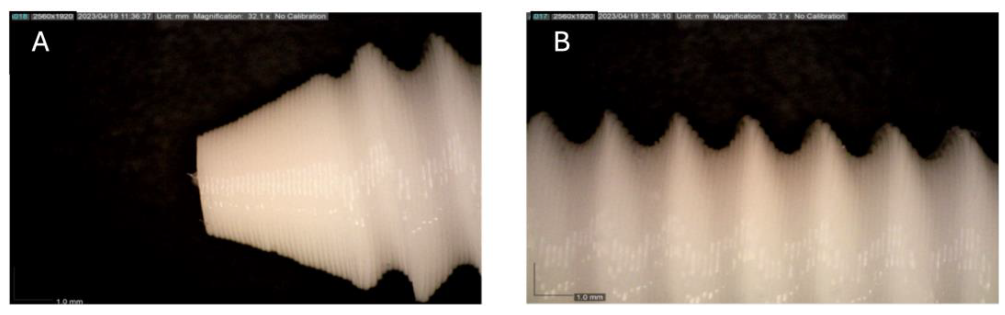
Figure 2.
Photographic record of the PLA screw after 1 month of exposure to simulated body fluid (A) top view showing the screw point and thread alignment; (B) side view highlighting the thread pitch and surface finish.
Figure 2.
Photographic record of the PLA screw after 1 month of exposure to simulated body fluid (A) top view showing the screw point and thread alignment; (B) side view highlighting the thread pitch and surface finish.
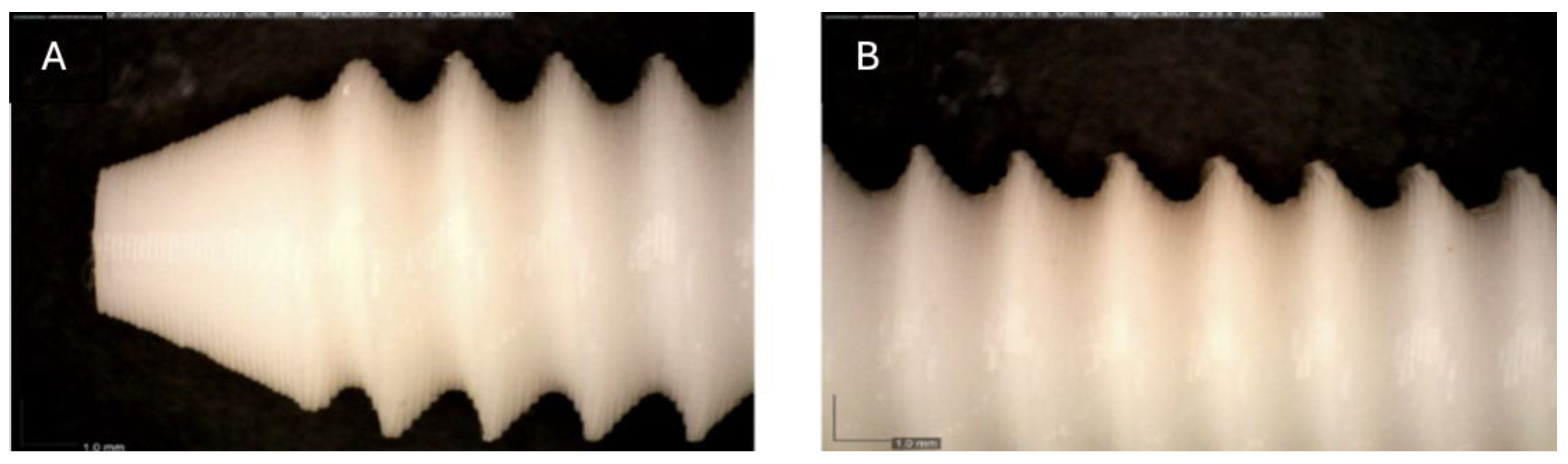
Figure 3.
Photographic record of the PLA screw after 2 months of exposure to simulated body fluid. (A) top view showing the screw point and thread alignment; (B) side view highlighting the thread pitch and surface finish.
Figure 3.
Photographic record of the PLA screw after 2 months of exposure to simulated body fluid. (A) top view showing the screw point and thread alignment; (B) side view highlighting the thread pitch and surface finish.
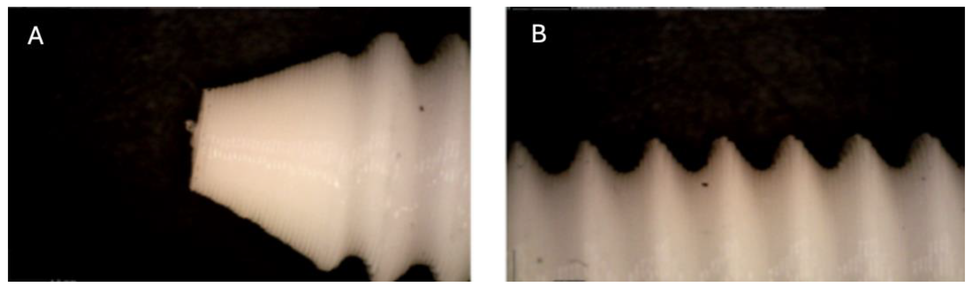
Figure 4.
Photographic record of the PLA screw after 3 months of exposure to simulated body fluid. (A) top view showing the screw point and thread alignment; (B) side view highlighting the thread pitch and surface finish.
Figure 4.
Photographic record of the PLA screw after 3 months of exposure to simulated body fluid. (A) top view showing the screw point and thread alignment; (B) side view highlighting the thread pitch and surface finish.
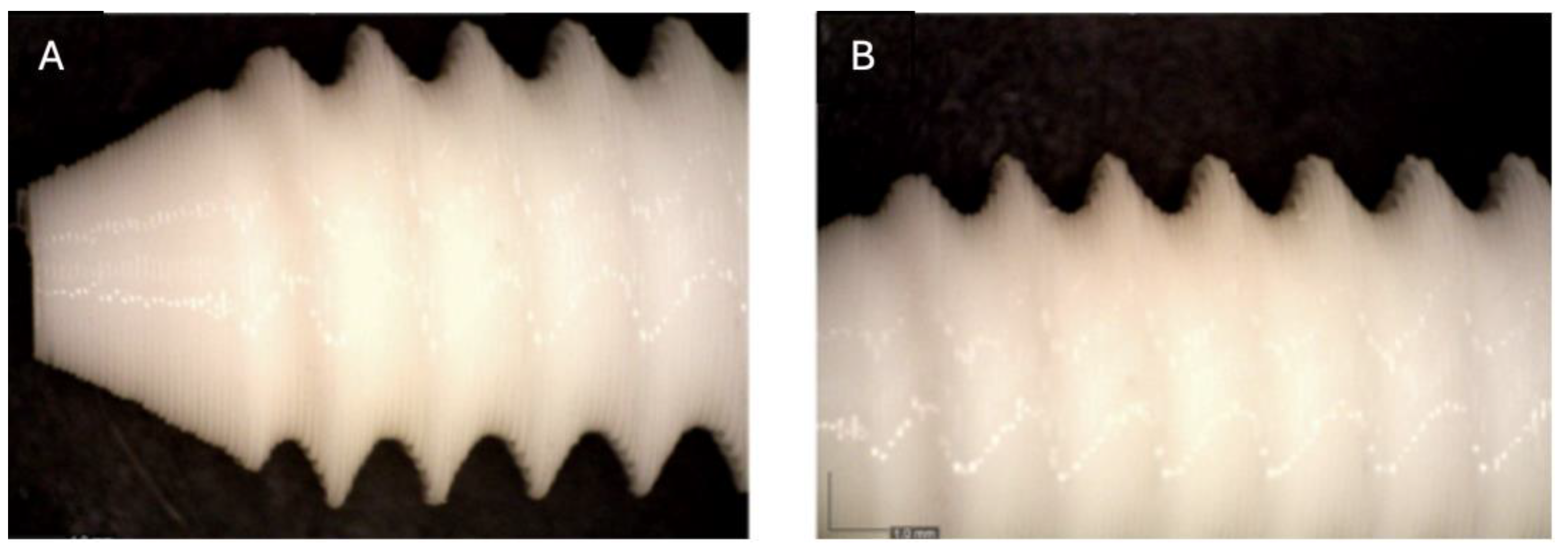
Figure 5.
Photographic record of the PLA screw after 4 months of exposure to simulated body fluid. (A) top view showing the screw point and thread alignment; (B) side view highlighting the thread pitch and surface finish.
Figure 5.
Photographic record of the PLA screw after 4 months of exposure to simulated body fluid. (A) top view showing the screw point and thread alignment; (B) side view highlighting the thread pitch and surface finish.
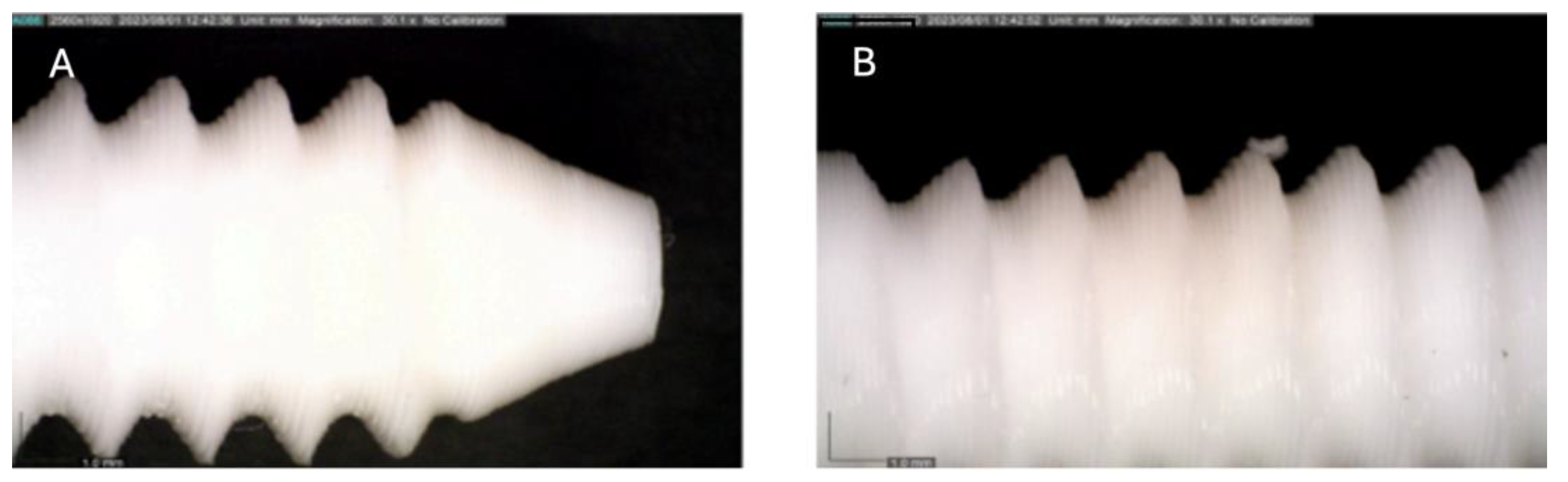
Figure 6.
Photographic record of the PLA screw after 5 months of exposure to simulated body fluid. (A) top view showing the screw head and thread alignment; (B) side view highlighting the thread pitch and surface finish; (C) top view showing the screw point.
Figure 6.
Photographic record of the PLA screw after 5 months of exposure to simulated body fluid. (A) top view showing the screw head and thread alignment; (B) side view highlighting the thread pitch and surface finish; (C) top view showing the screw point.
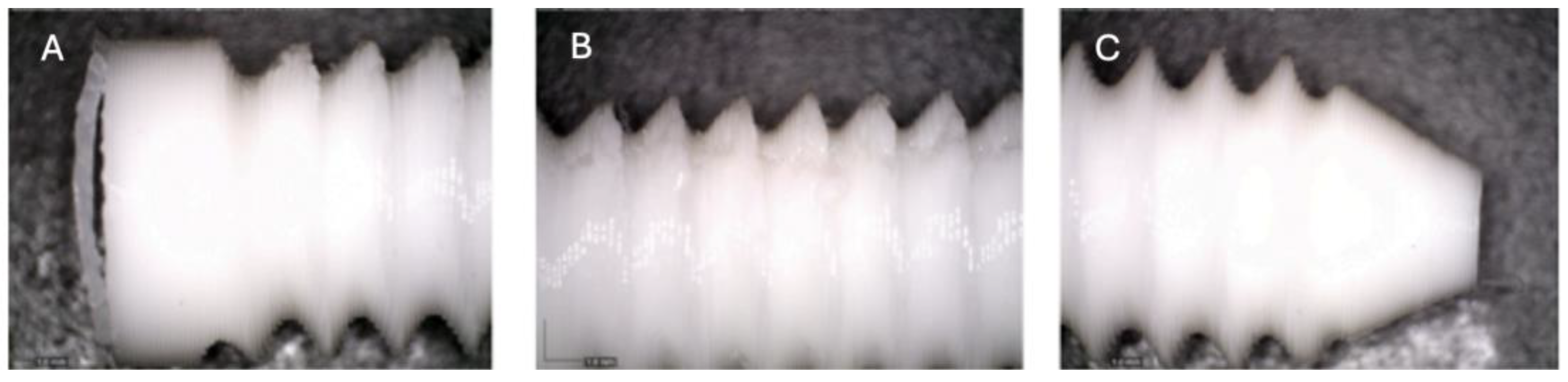
Figure 7.
Photographic record of the PLA screw after 6 months of exposure to simulated body fluid. (A) top view showing the screw point and thread alignment; (B) side view highlighting the thread pitch and surface finish.
Figure 7.
Photographic record of the PLA screw after 6 months of exposure to simulated body fluid. (A) top view showing the screw point and thread alignment; (B) side view highlighting the thread pitch and surface finish.
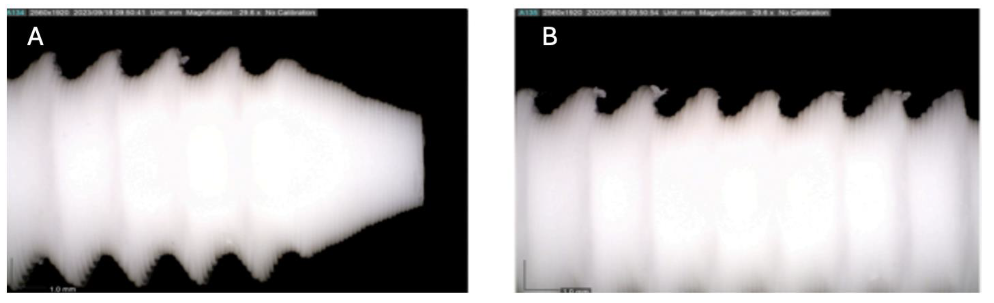
Figure 8.
Photographic record of the PLA screw after 7 months of exposure to simulated body fluid. (A) top view showing the screw point and thread alignment; (B) side view highlighting the thread pitch and surface finish.
Figure 8.
Photographic record of the PLA screw after 7 months of exposure to simulated body fluid. (A) top view showing the screw point and thread alignment; (B) side view highlighting the thread pitch and surface finish.
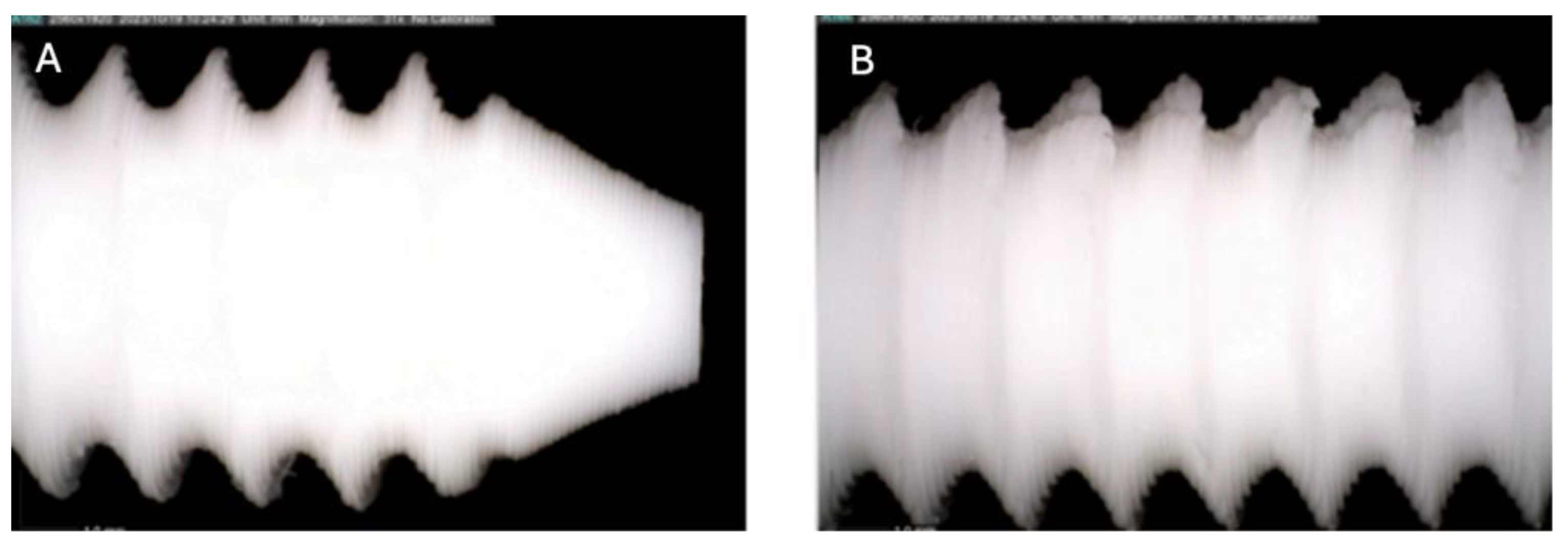
Figure 9.
Photographic record of the PLA screw after 8 months of exposure to simulated body fluid. (A) top view showing the screw point and thread alignment; (B) side view highlighting the thread pitch and surface finish.
Figure 9.
Photographic record of the PLA screw after 8 months of exposure to simulated body fluid. (A) top view showing the screw point and thread alignment; (B) side view highlighting the thread pitch and surface finish.
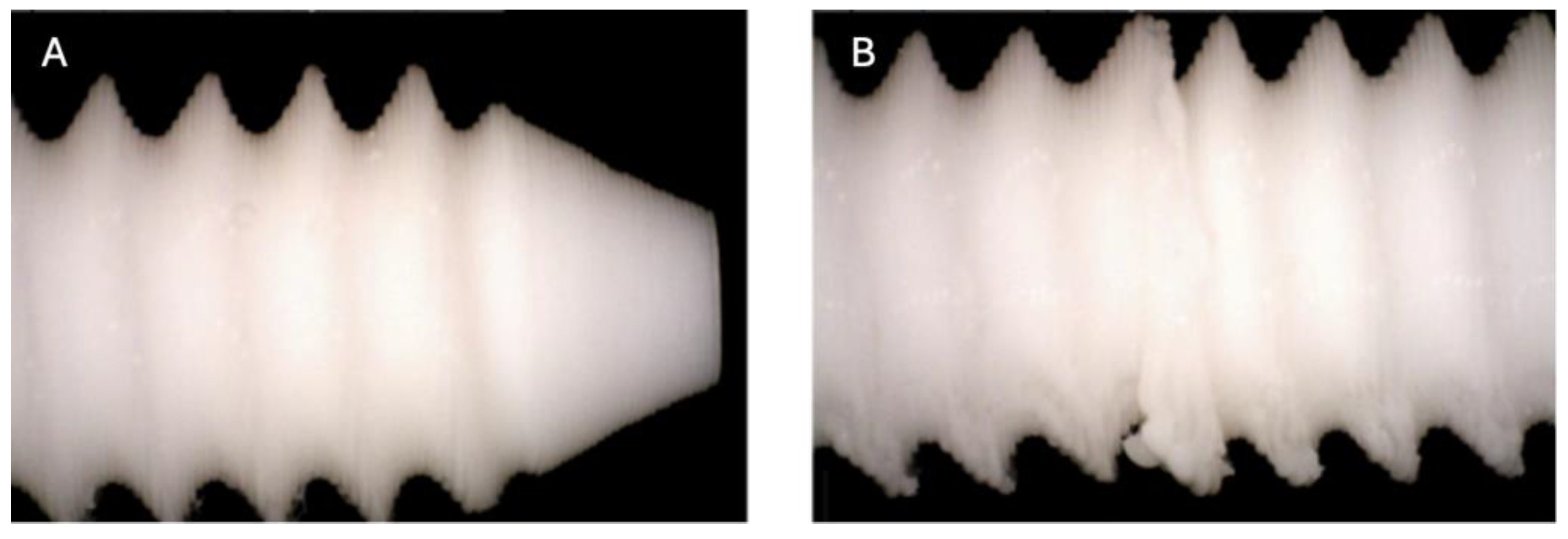
Figure 10.
Photographic record of the PLA screw after 9 months of exposure to simulated body fluid. (A) top view showing the screw point and thread alignment; (B) side view highlighting the thread pitch and surface finish.
Figure 10.
Photographic record of the PLA screw after 9 months of exposure to simulated body fluid. (A) top view showing the screw point and thread alignment; (B) side view highlighting the thread pitch and surface finish.
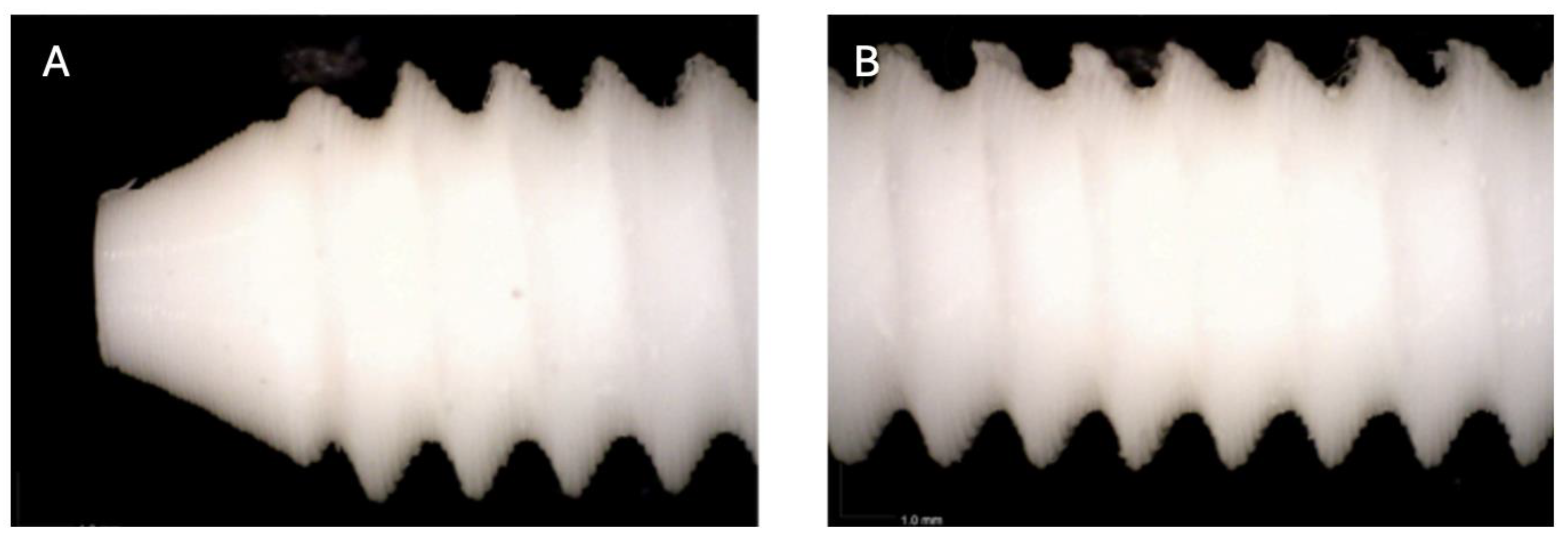
Figure 11.
Photographic record of the PLA screw after 10 months of exposure to simulated body fluid. (A) top view showing the screw point (B, C, D) side view highlighting the thread pitch and surface finish.
Figure 11.
Photographic record of the PLA screw after 10 months of exposure to simulated body fluid. (A) top view showing the screw point (B, C, D) side view highlighting the thread pitch and surface finish.
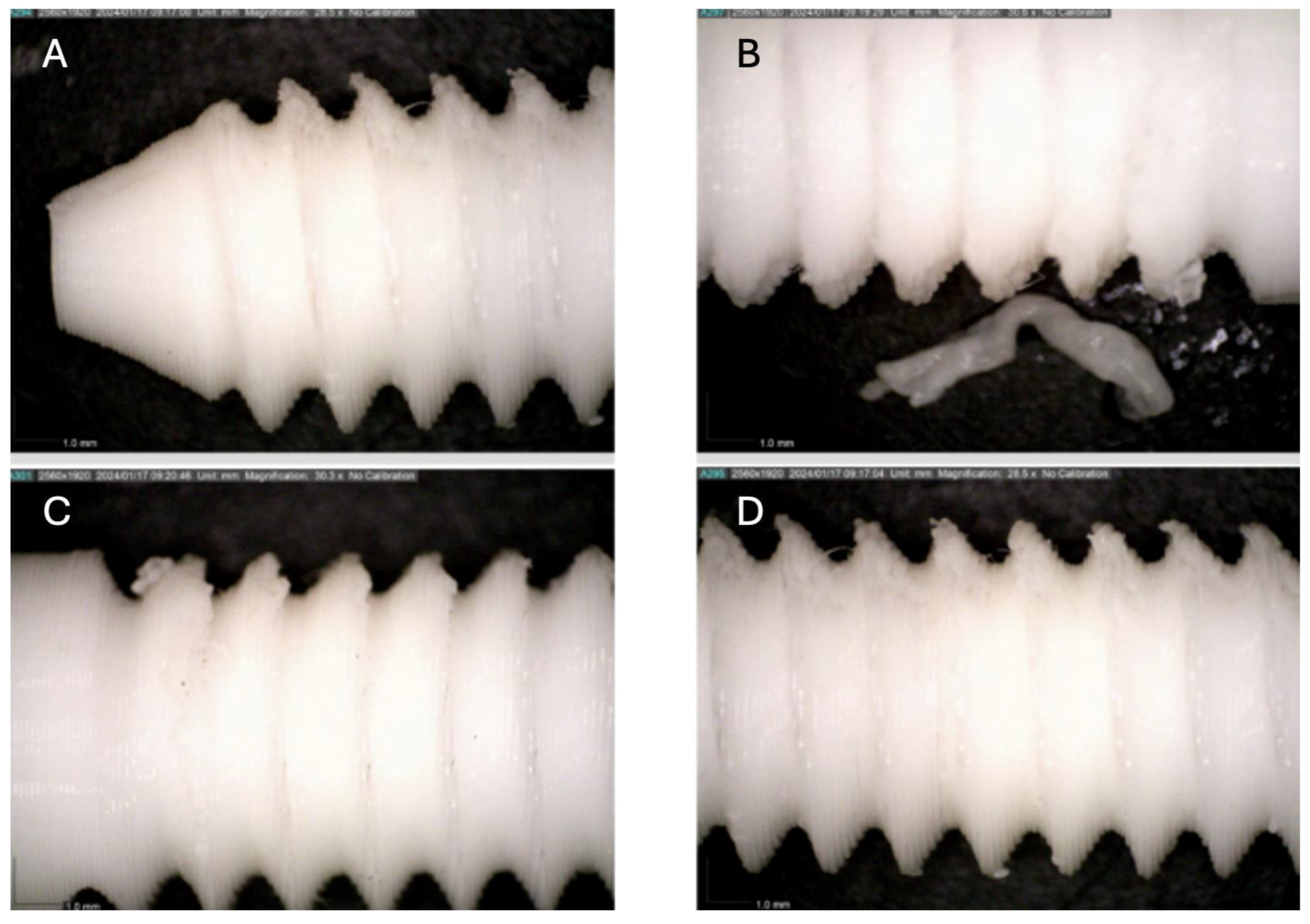
Figure 12.
Computed tomography study of the right femur sample, one-month post-surgery, with PLA material. (A) axial slice, (B) sagittal reconstruction, and (C) 3D visualisation.
Figure 12.
Computed tomography study of the right femur sample, one-month post-surgery, with PLA material. (A) axial slice, (B) sagittal reconstruction, and (C) 3D visualisation.
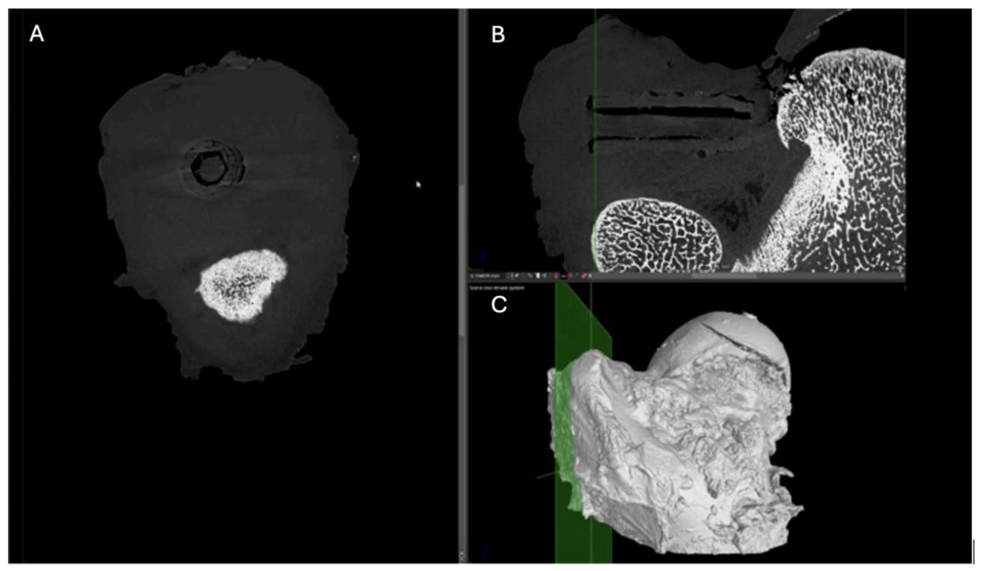
Figure 13.
Computed tomography study of the right femur sample, one-month post-surgery, with PEEK material. (A) axial slice, (B) sagittal reconstruction, and (C) 3D visualisation.
Figure 13.
Computed tomography study of the right femur sample, one-month post-surgery, with PEEK material. (A) axial slice, (B) sagittal reconstruction, and (C) 3D visualisation.
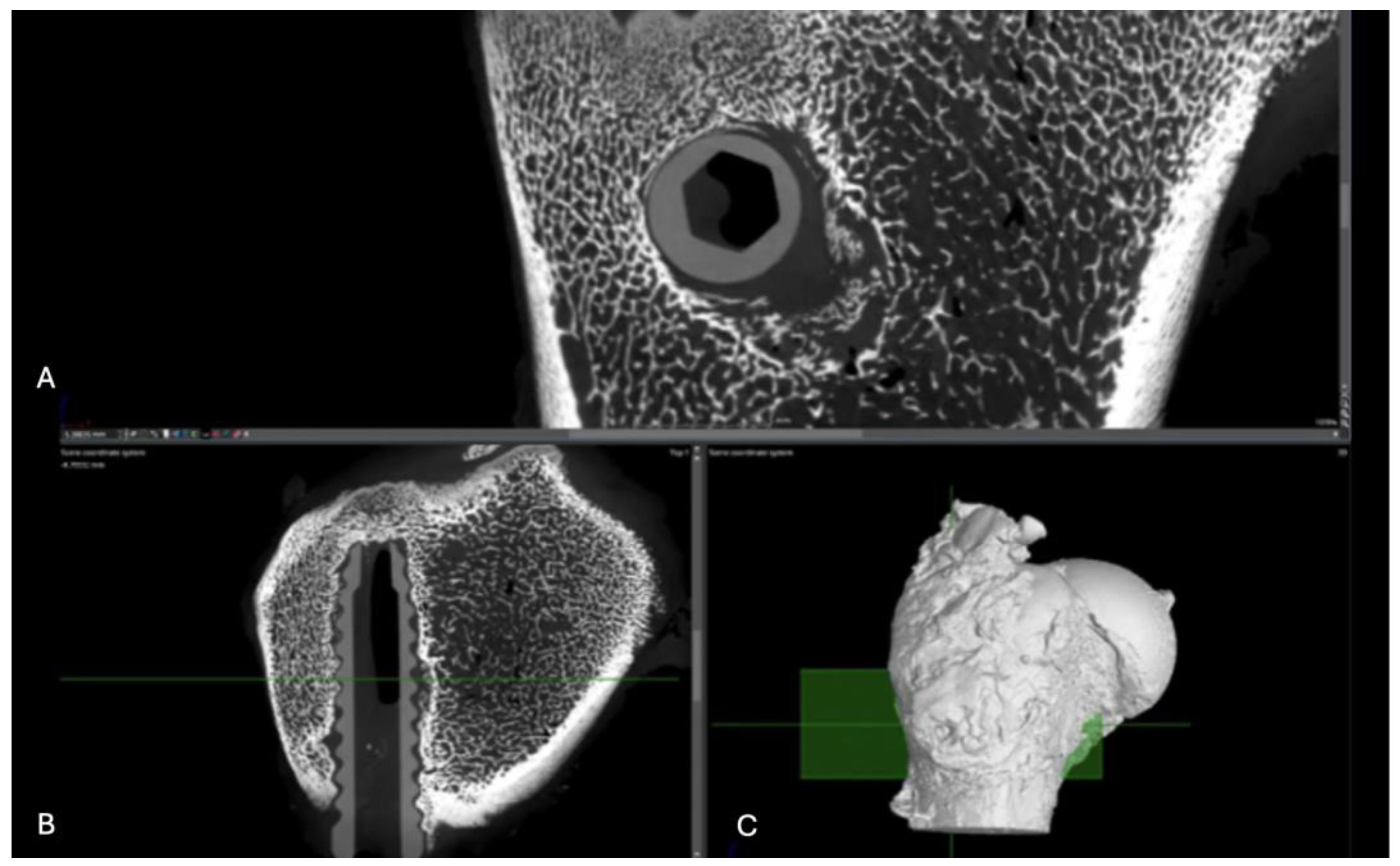
Figure 14.
Computed tomography study (A) axial slice, (B,D,E,F) sagittal reconstruction, and (C) 3D visualisation of the left femur sample, one-month post-surgery, with PLDLLA material.
Figure 14.
Computed tomography study (A) axial slice, (B,D,E,F) sagittal reconstruction, and (C) 3D visualisation of the left femur sample, one-month post-surgery, with PLDLLA material.
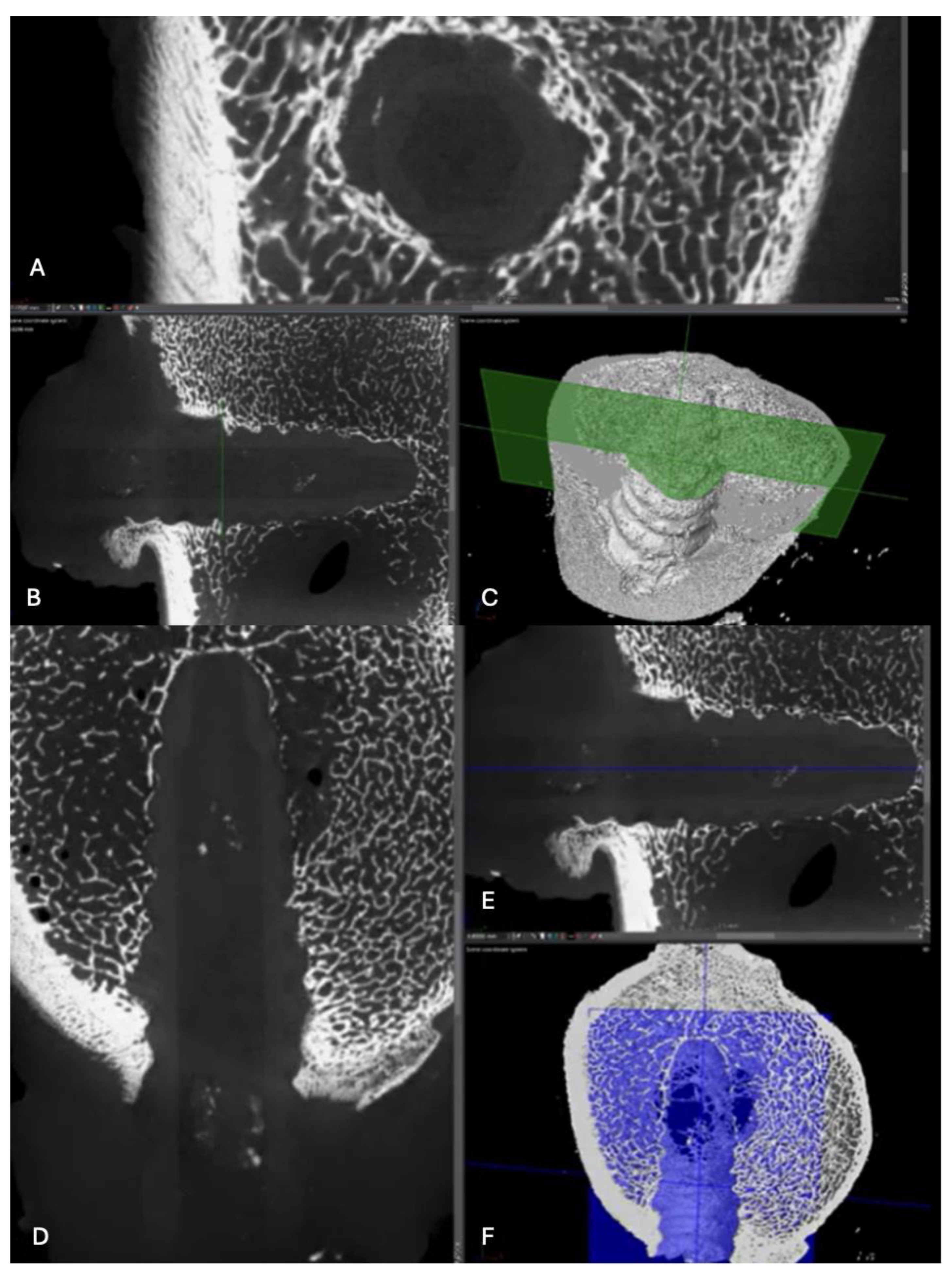
Figure 15.
Computed tomography study (A) sagittal reconstruction (B) axial slice, and (C) 3D imaging of the left femur sample, two-month post-surgery, with PLA material.
Figure 15.
Computed tomography study (A) sagittal reconstruction (B) axial slice, and (C) 3D imaging of the left femur sample, two-month post-surgery, with PLA material.
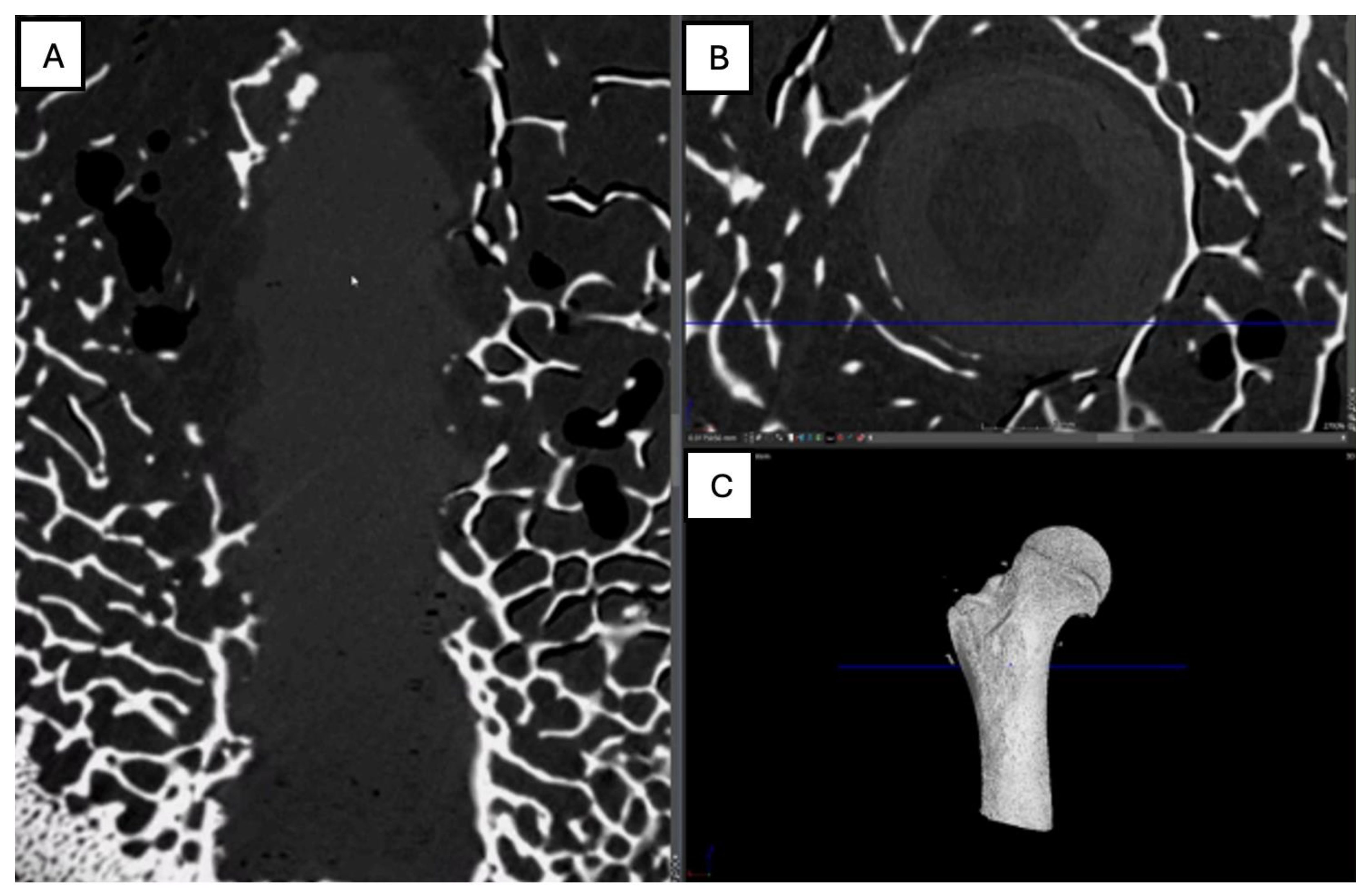
Figure 16.
Computed tomography study of the right femur sample, two-month post-surgery, with PEEK material. (A) axial slice, (B,D,E,F) sagittal reconstruction, and (C) 3D imaging.
Figure 16.
Computed tomography study of the right femur sample, two-month post-surgery, with PEEK material. (A) axial slice, (B,D,E,F) sagittal reconstruction, and (C) 3D imaging.
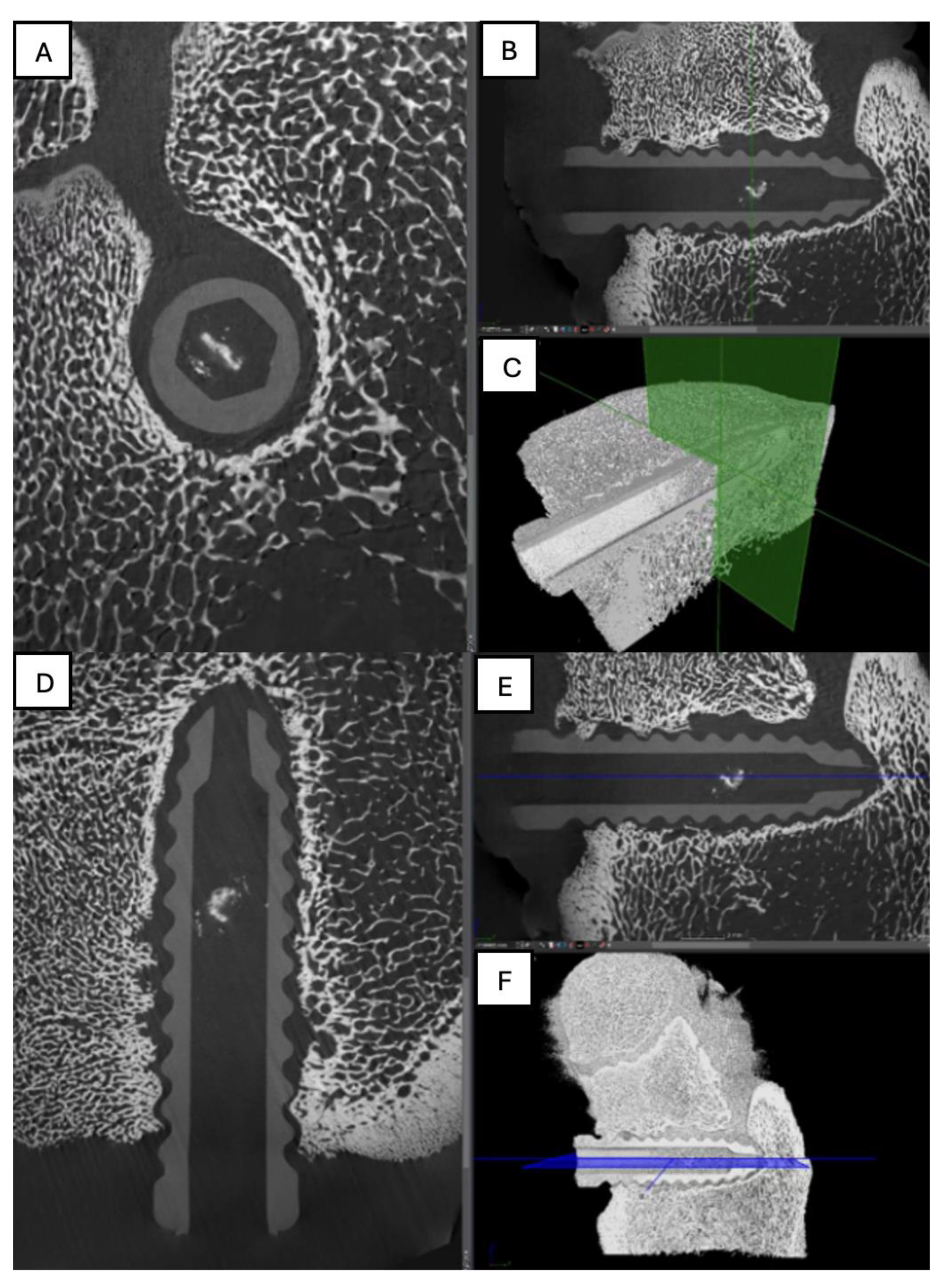
Figure 17.
Computed tomography study of the left femur sample, (A,B,C) sagittal reconstruction. two-month post-surgery, with PLDLLA material.
Figure 17.
Computed tomography study of the left femur sample, (A,B,C) sagittal reconstruction. two-month post-surgery, with PLDLLA material.
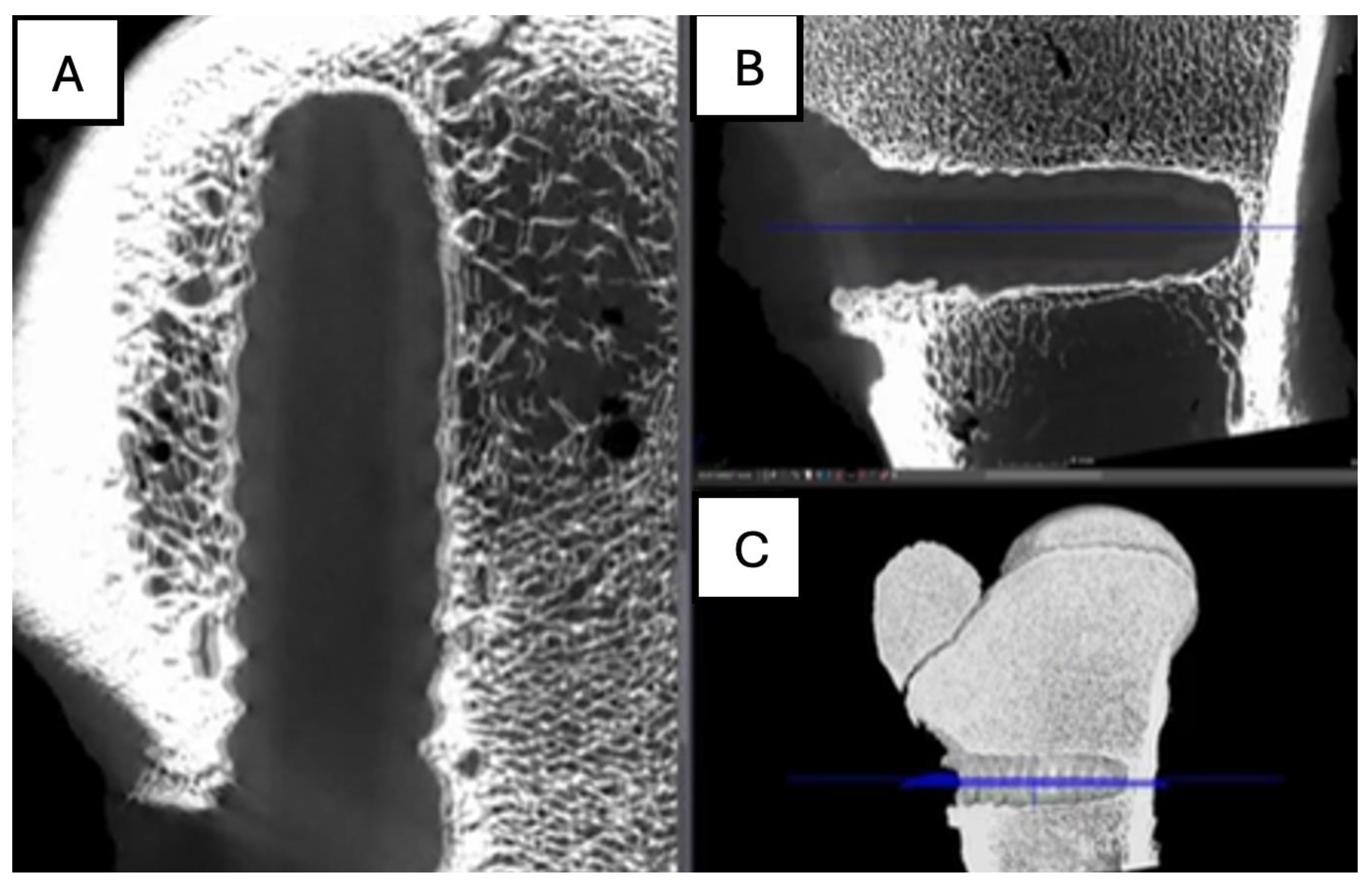
Figure 18.
Computed tomography study of the right femur sample, three-month post-surgery, with PLA material. . (A) sagittal reconstruction, (B) axial and (C) 3D imaging.
Figure 18.
Computed tomography study of the right femur sample, three-month post-surgery, with PLA material. . (A) sagittal reconstruction, (B) axial and (C) 3D imaging.
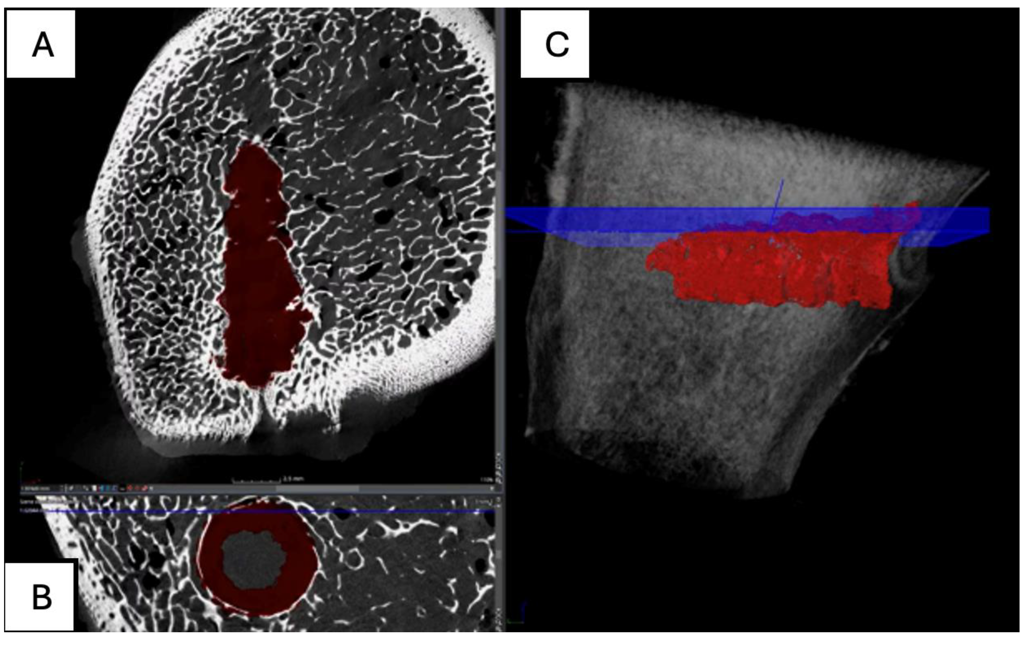
Figure 19.
Computed tomography study of the right femur sample, three-month post-surgery, with PEEK material. (A,B,C,E,F) sagittal and (D) axial reconstruction.
Figure 19.
Computed tomography study of the right femur sample, three-month post-surgery, with PEEK material. (A,B,C,E,F) sagittal and (D) axial reconstruction.
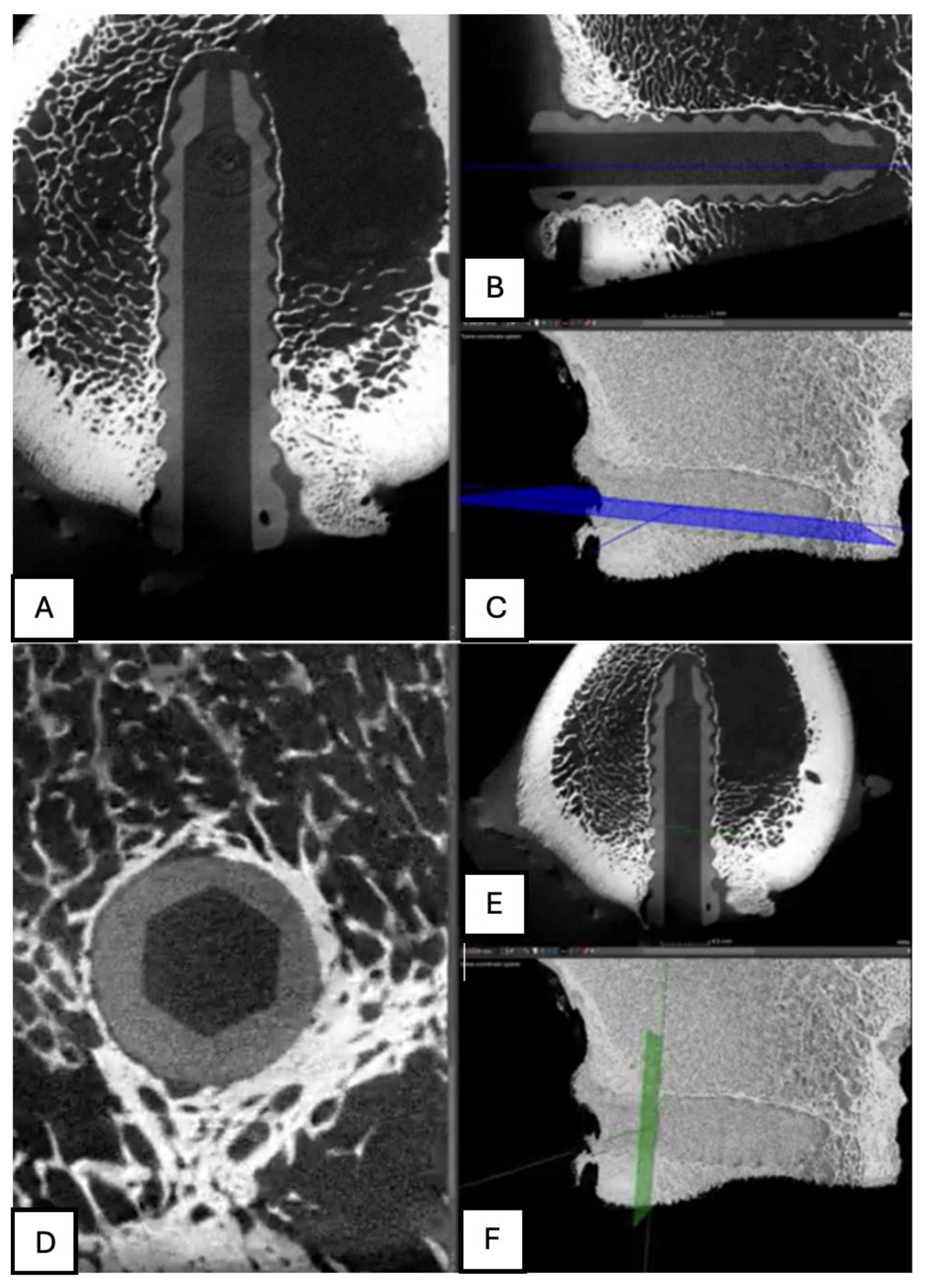
Figure 20.
Computed tomography study of the left femur sample, three-month post-surgery, with PLDLLA material. (A, F)Axial and (B,C,D,E) sagittal reconstruction.
Figure 20.
Computed tomography study of the left femur sample, three-month post-surgery, with PLDLLA material. (A, F)Axial and (B,C,D,E) sagittal reconstruction.
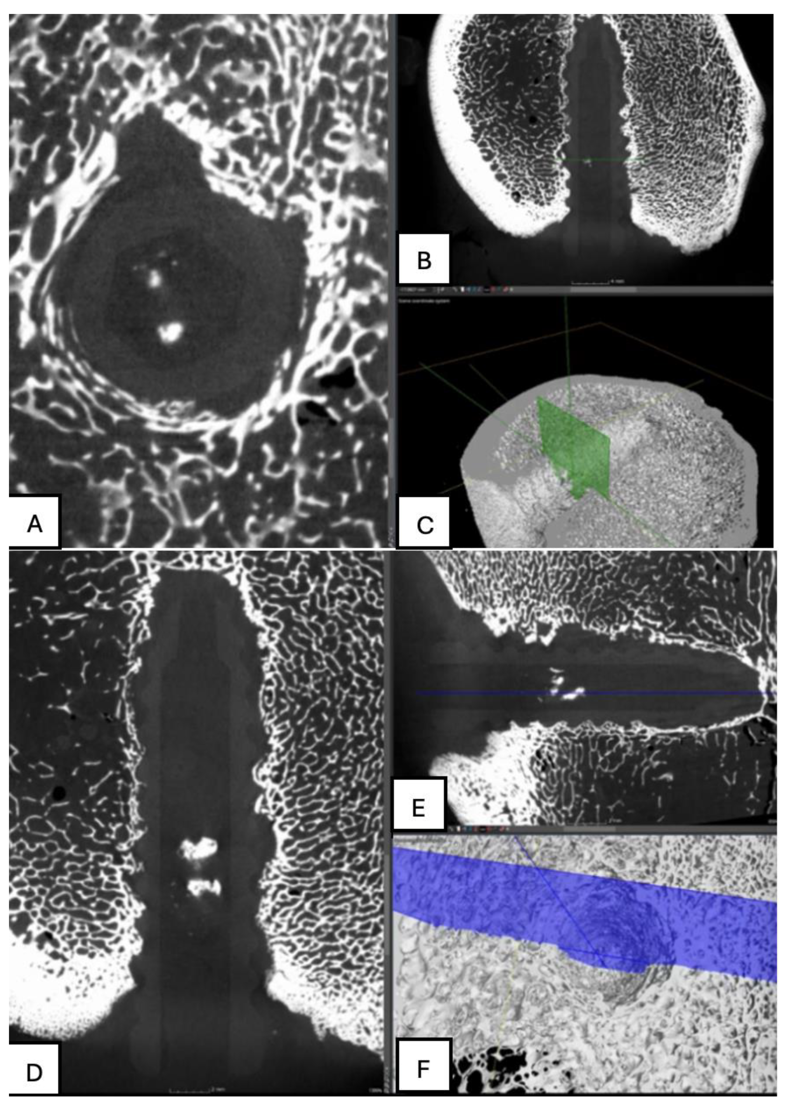
Figure 21.
Computed tomography study of the left femur sample, fourth-month post-surgery, with PLA material. (A) axial, (B) sagittal reconstruction and(C) 3D imaging.
Figure 21.
Computed tomography study of the left femur sample, fourth-month post-surgery, with PLA material. (A) axial, (B) sagittal reconstruction and(C) 3D imaging.
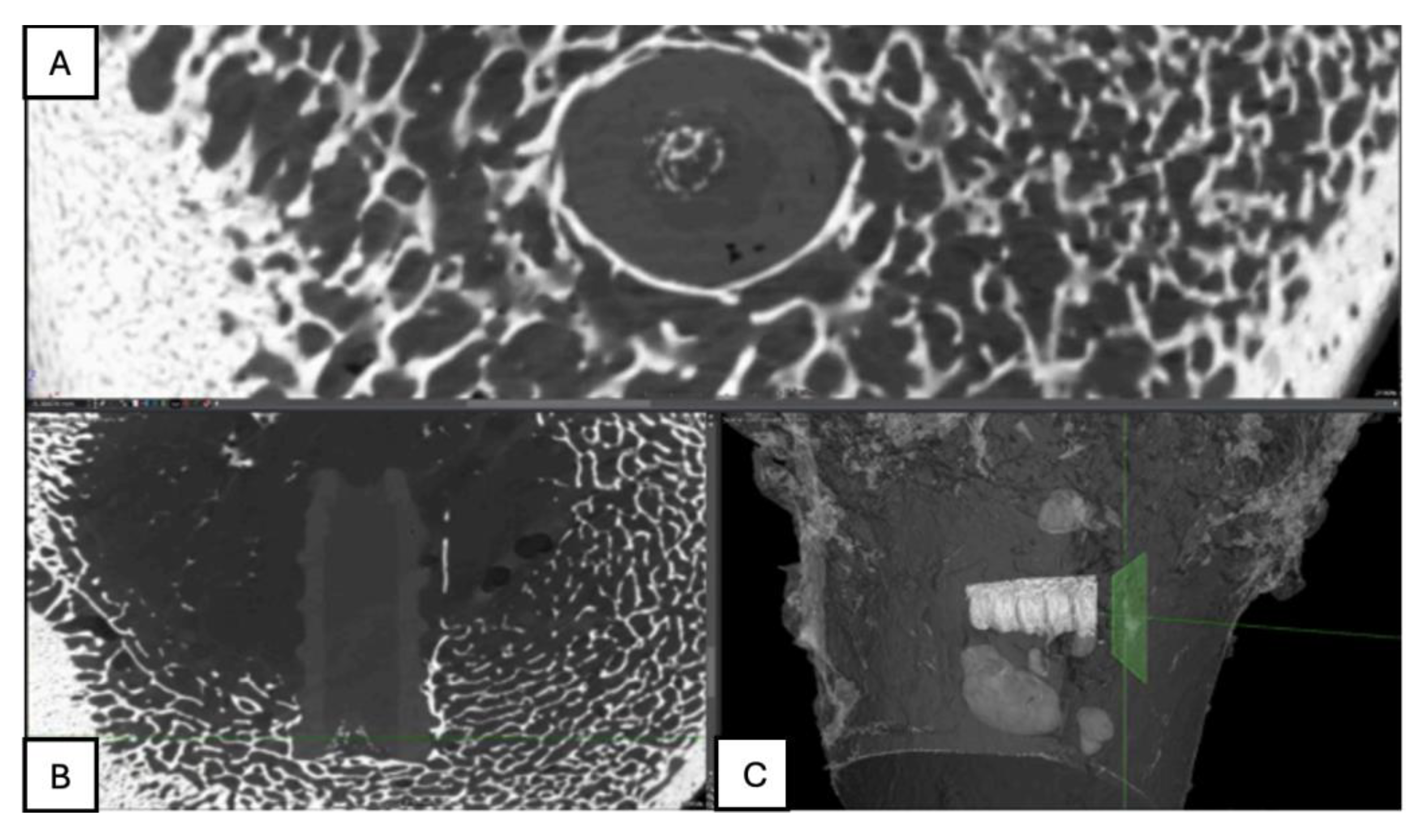
Figure 22.
Computed tomography study of the right femur sample, fourth-month post-surgery, with PEEK material. (A,B,C) sagittal reconstruction.
Figure 22.
Computed tomography study of the right femur sample, fourth-month post-surgery, with PEEK material. (A,B,C) sagittal reconstruction.
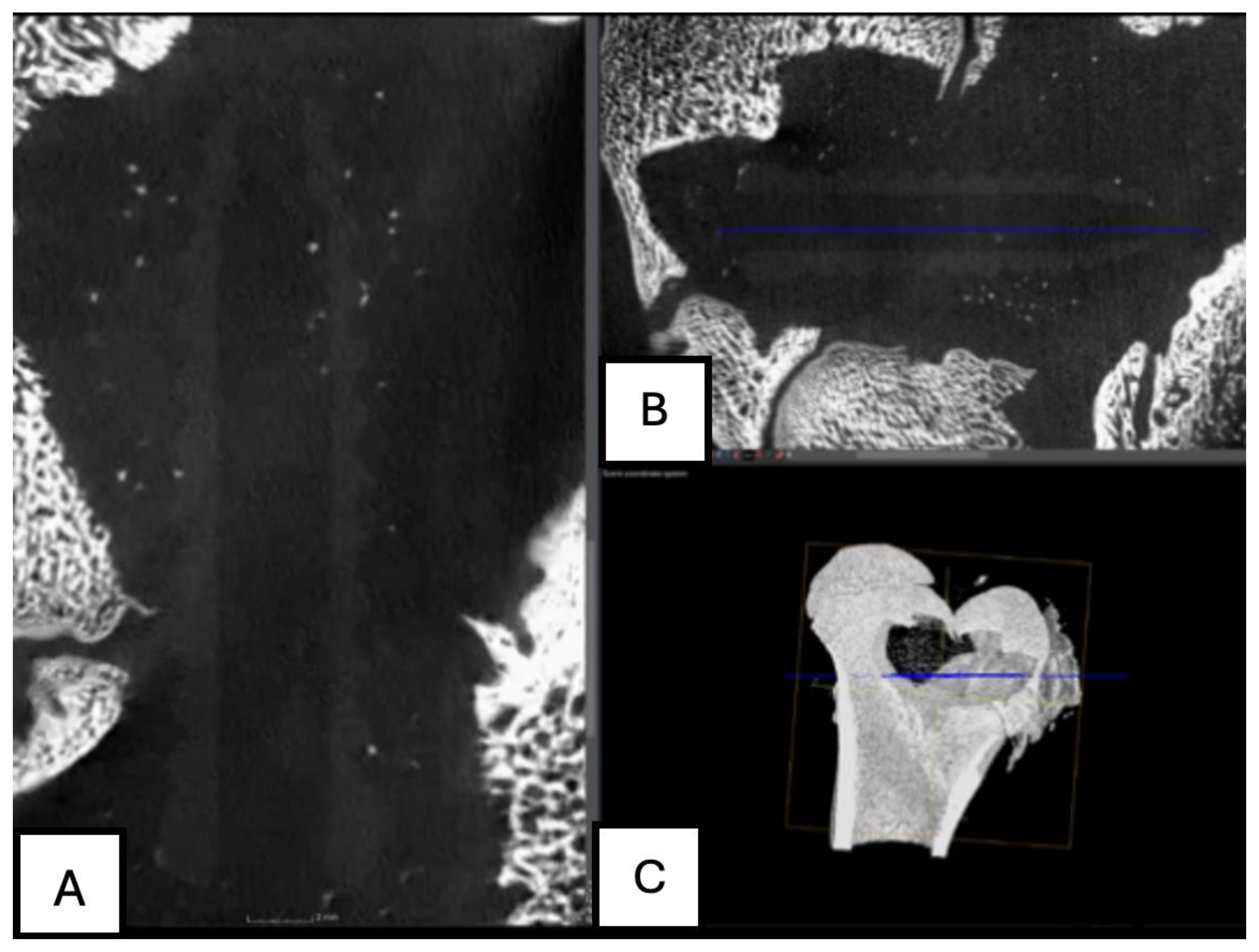
Figure 23.
Computed tomography study of the left femur sample, fourth-month post-surgery, with PLDLLA material. (A,B,C,E,F) Sagittal and (D) axial reconstruction.
Figure 23.
Computed tomography study of the left femur sample, fourth-month post-surgery, with PLDLLA material. (A,B,C,E,F) Sagittal and (D) axial reconstruction.
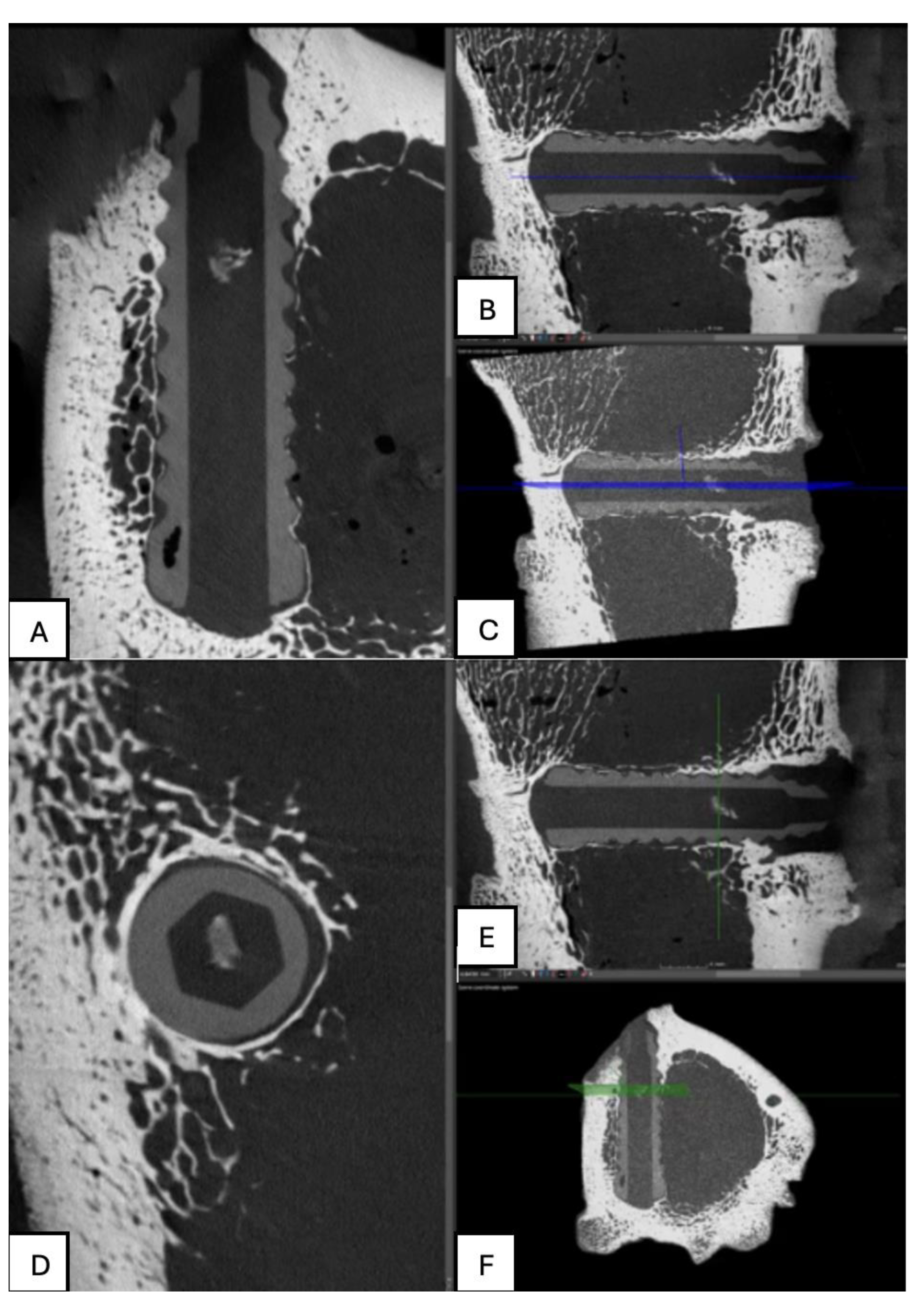
Figure 24.
(A) PLA screw insertion site is in the articular cartilage. (B) presence of small-caliber blood vessels scattered throughout the tissue, along with signs of synovial metaplasia in the epithelium surrounding the screw.
Figure 24.
(A) PLA screw insertion site is in the articular cartilage. (B) presence of small-caliber blood vessels scattered throughout the tissue, along with signs of synovial metaplasia in the epithelium surrounding the screw.
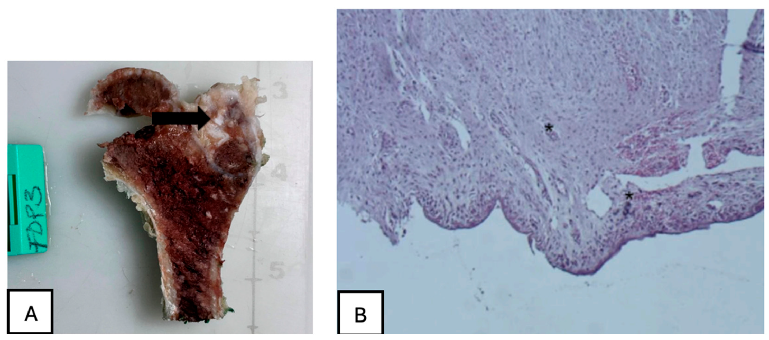
Figure 25.
PEEK screw histological analysis reveals absence of osseointegration and presence of fibrointegration with fibrous tissue interposed between the implant and the surrounding bone.
Figure 25.
PEEK screw histological analysis reveals absence of osseointegration and presence of fibrointegration with fibrous tissue interposed between the implant and the surrounding bone.
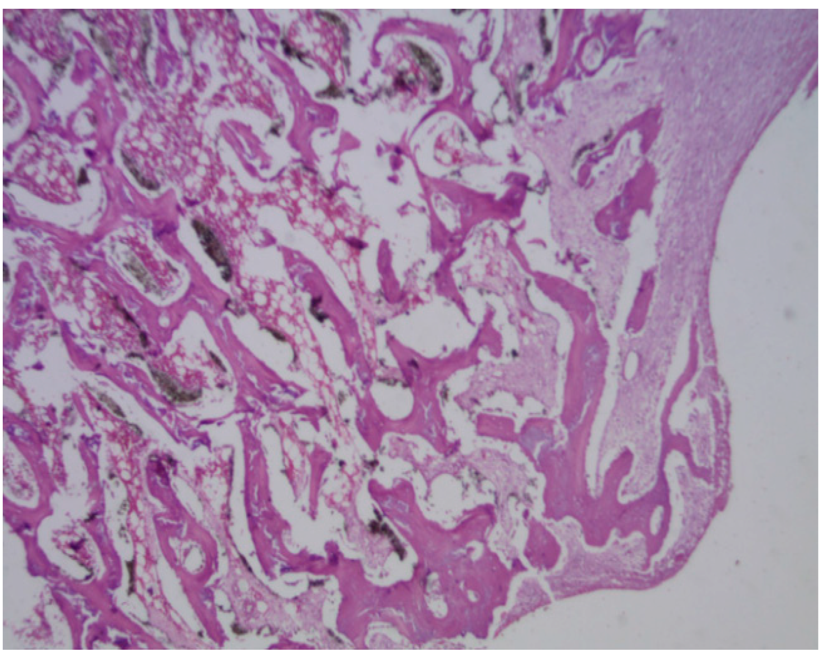
Figure 26.
PLDLLA periprosthetic fibrosis is mild, indicating a moderate tissue response without excessive fibrous encapsulation.
Figure 26.
PLDLLA periprosthetic fibrosis is mild, indicating a moderate tissue response without excessive fibrous encapsulation.
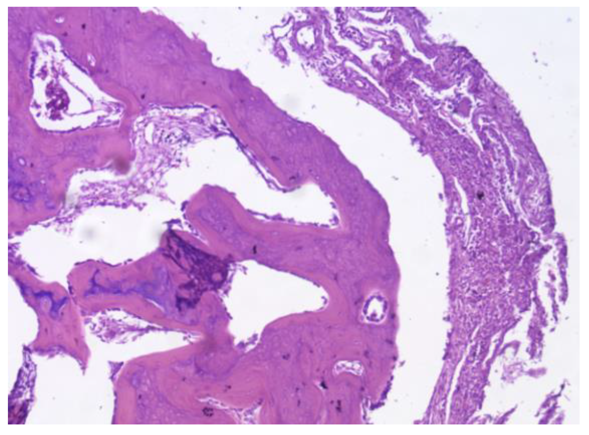
Figure 27.
(A) PLA screw is in the metaphyseal region; (B) At 20x magnification, no signs of periprosthetic inflammation are observed, unlike the first month there is no evidence of synovial metaplasia or neovascularization, suggesting stabilization of the local tissue response.
Figure 27.
(A) PLA screw is in the metaphyseal region; (B) At 20x magnification, no signs of periprosthetic inflammation are observed, unlike the first month there is no evidence of synovial metaplasia or neovascularization, suggesting stabilization of the local tissue response.
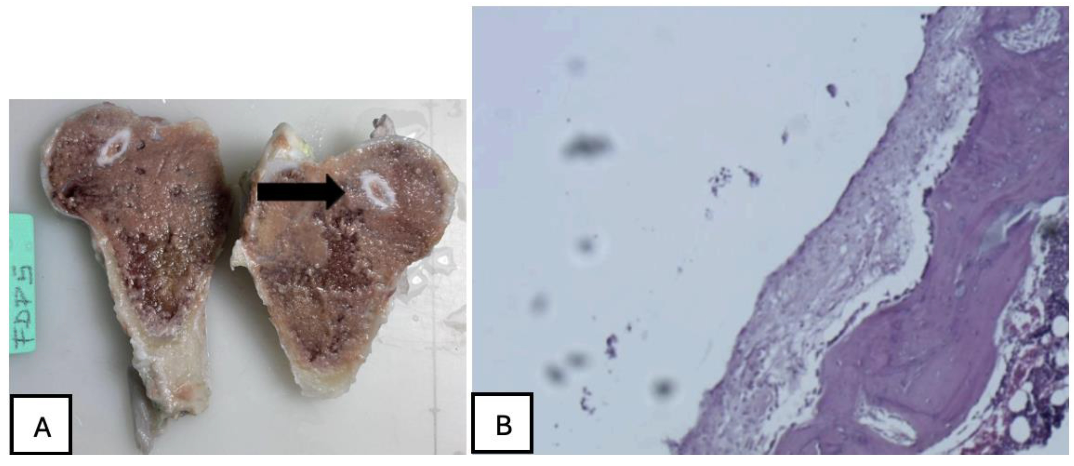
Figure 28.
Mature connective tissue with prominent neovascularisation was observed in PEEK screw histological analysis, indicating an active attempt at vascular regeneration in the periprosthetic area.
Figure 28.
Mature connective tissue with prominent neovascularisation was observed in PEEK screw histological analysis, indicating an active attempt at vascular regeneration in the periprosthetic area.
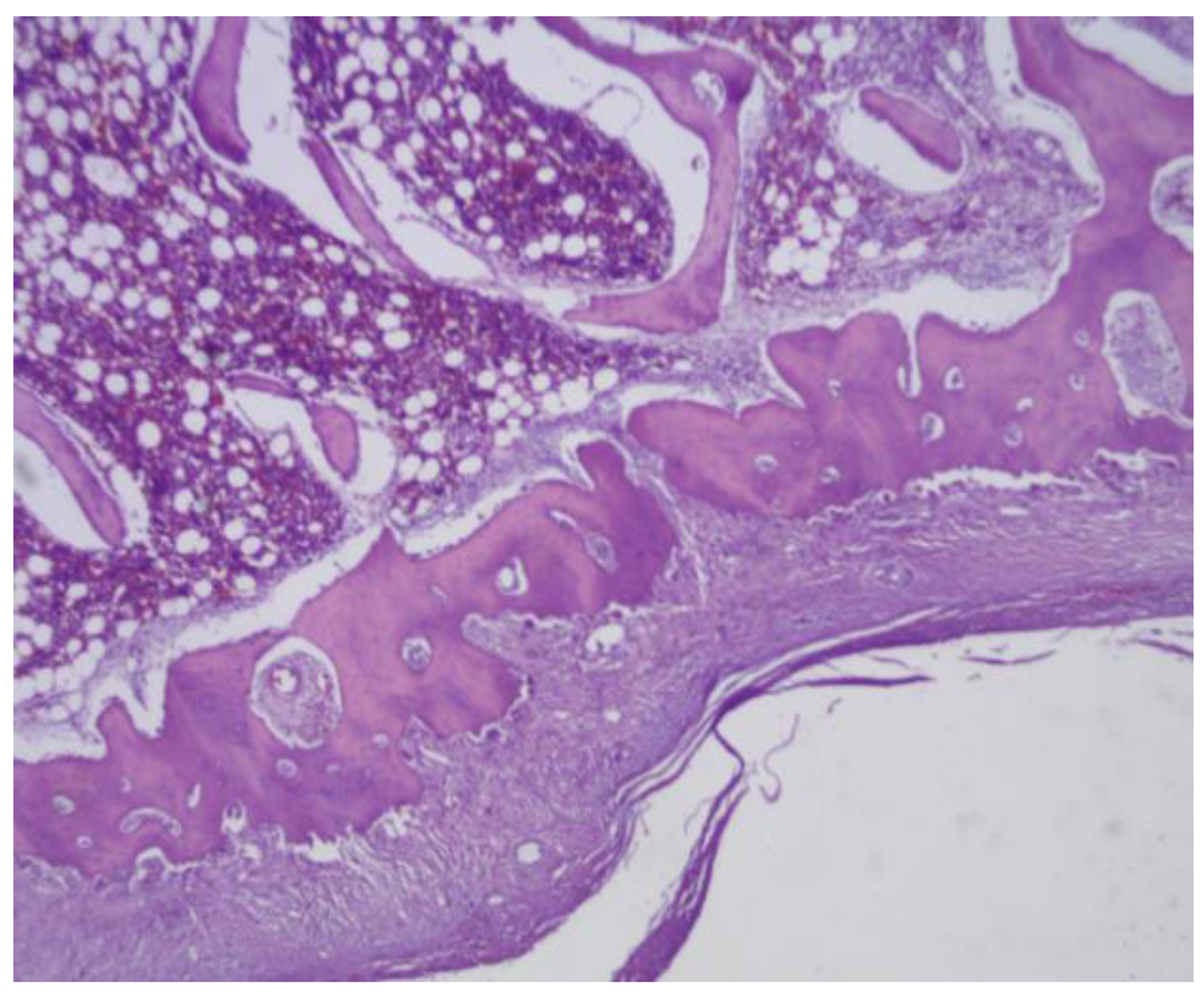
Figure 29.
The presence of mature bone, indicates a favourable osteointegrative environment in PLDLLA screw.
Figure 29.
The presence of mature bone, indicates a favourable osteointegrative environment in PLDLLA screw.
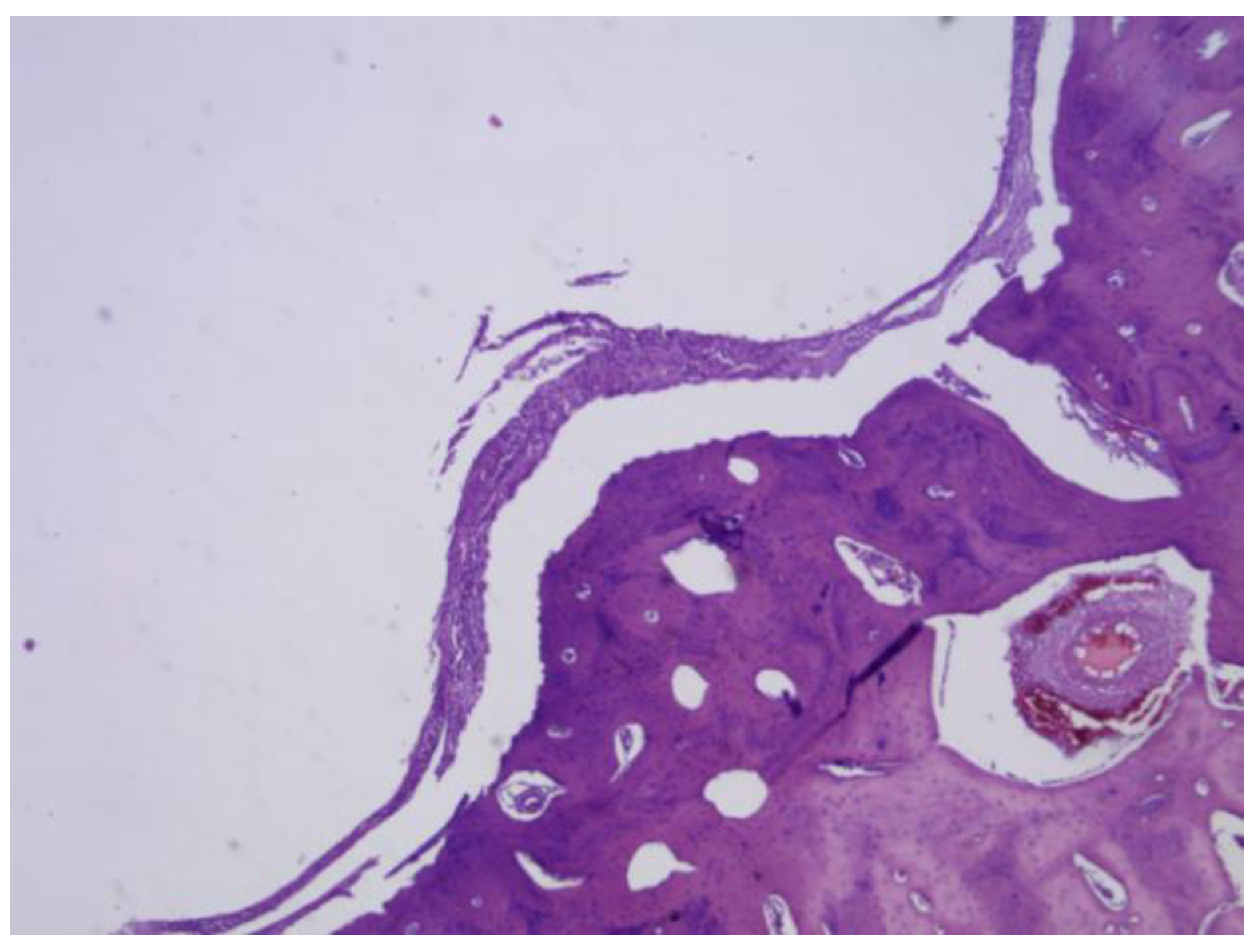
Figure 30.
(A) PLA screw is in the epiphyseally region. (B) Mild presence of loose connective tissue was identified histologically, representing a modest degree of periprosthetic fibrosis.
Figure 30.
(A) PLA screw is in the epiphyseally region. (B) Mild presence of loose connective tissue was identified histologically, representing a modest degree of periprosthetic fibrosis.
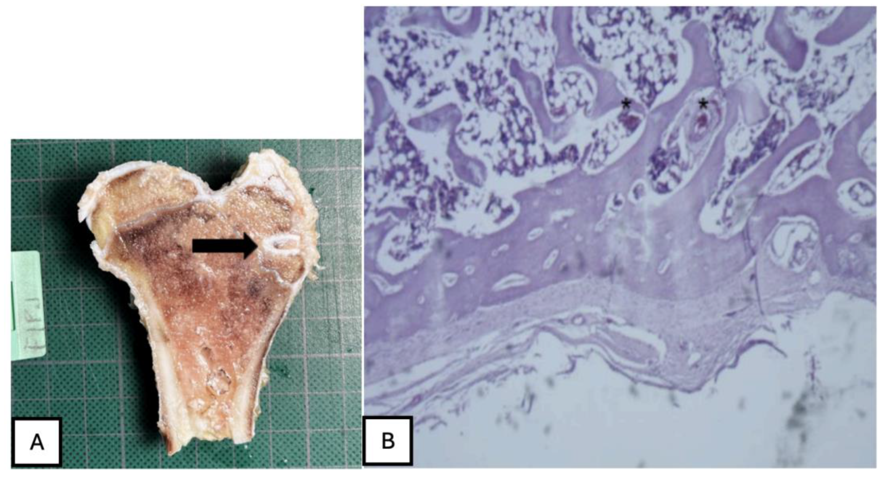
Figure 31.
No osteoid formation or synovial metaplasia was identified, indicating the absence of abnormal bone matrix deposition or undesirable cellular transformation.
Figure 31.
No osteoid formation or synovial metaplasia was identified, indicating the absence of abnormal bone matrix deposition or undesirable cellular transformation.
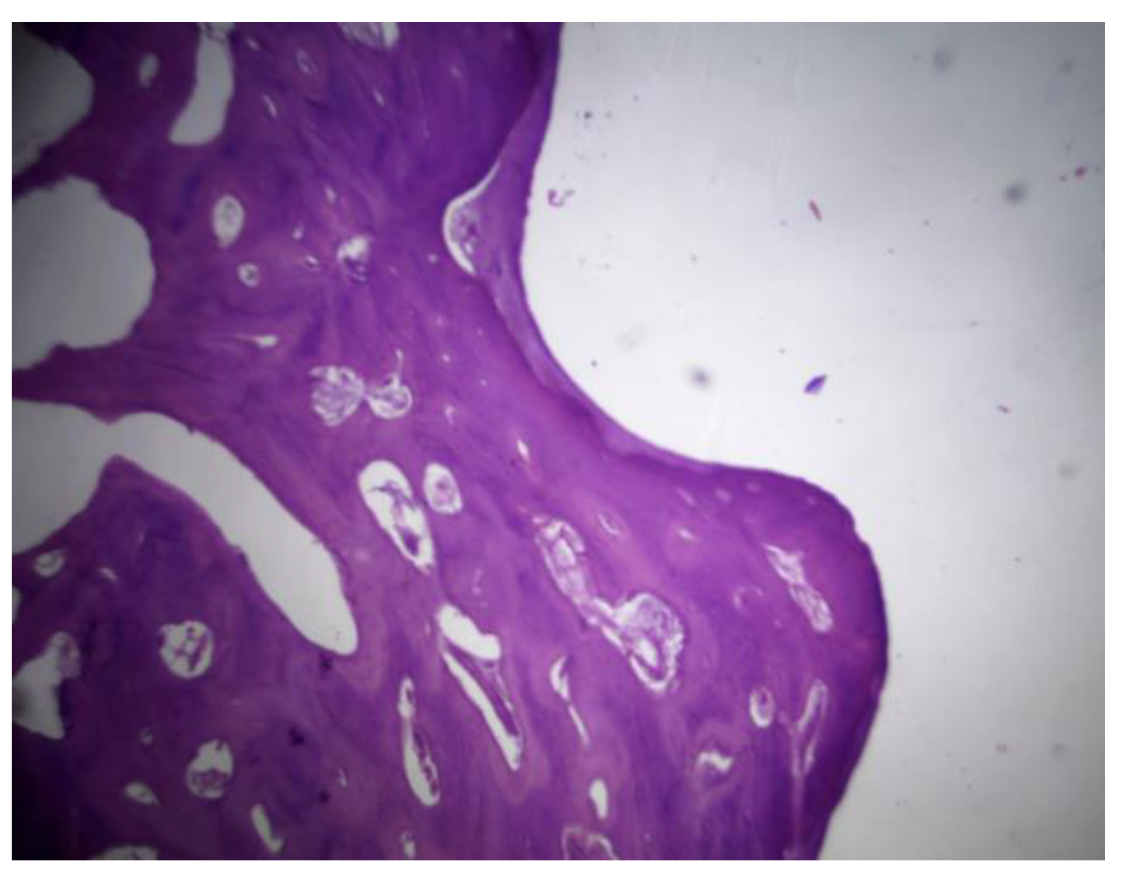
Figure 32.
(A) PLA screw is in the diaphyseal region. (B) signs of osteointegration were apparent, demonstrating direct interaction between bone tissue and the implant surface. Sparse neovascularisation was observed, suggesting limited yet active vascular development in the area.
Figure 32.
(A) PLA screw is in the diaphyseal region. (B) signs of osteointegration were apparent, demonstrating direct interaction between bone tissue and the implant surface. Sparse neovascularisation was observed, suggesting limited yet active vascular development in the area.
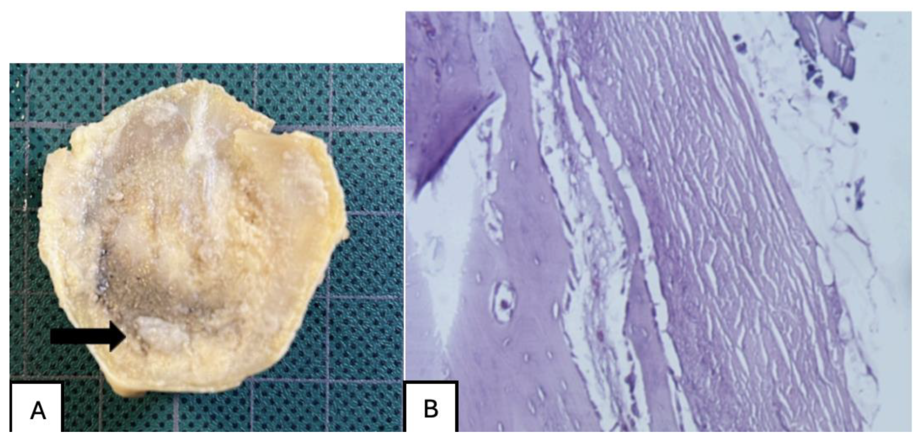
Figure 33.
PLDLLA histological analysis shows cortical bone in close apposition to the prosthesis, accompanied by mature periprosthetic fibrosis.
Figure 33.
PLDLLA histological analysis shows cortical bone in close apposition to the prosthesis, accompanied by mature periprosthetic fibrosis.
Disclaimer/Publisher’s Note: The statements, opinions and data contained in all publications are solely those of the individual author(s) and contributor(s) and not of MDPI and/or the editor(s). MDPI and/or the editor(s) disclaim responsibility for any injury to people or property resulting from any ideas, methods, instructions or products referred to in the content. |
© 2025 by the authors. Licensee MDPI, Basel, Switzerland. This article is an open access article distributed under the terms and conditions of the Creative Commons Attribution (CC BY) license (http://creativecommons.org/licenses/by/4.0/).
Copyright: This open access article is published under a Creative Commons CC BY 4.0 license, which permit the free download, distribution, and reuse, provided that the author and preprint are cited in any reuse.


