Submitted:
28 May 2025
Posted:
28 May 2025
You are already at the latest version
Abstract
The study presents an innovative pipeline for processing, compressing, and remotely visualizing large-scale numerical simulations of fluid dynamics in a virtual wind tunnel (VWT), leveraging Virtual and Augmented Reality (VR/AR) for enhanced analysis and high-end visualization. The workflow addresses the challenges of handling massive databases obtained via Direct Numerical Simulation (DNS) while maintaining visual fidelity, promoting full immersion, and ensuring efficient rendering for user interaction. We are performing fully immersive visualization of high-fidelity numerical results of supersonic spatially-developing turbulent boundary layers (SDTBL) under strong concave/convex curvatures at a freestream Mach number of 2.86 (i.e., supersonic flow). The selected numerical tool is Direct Numerical Simulation (DNS) with high spatial/temporal resolution. The comprehensive DNS information sheds important light on the transport phenomena inside turbulent boundary layers subject to strong deceleration or Adverse Pressure Gradient (APG) caused by concave walls as well as to strong acceleration or Favorable Pressure Gradient (FPG) caused by convex walls at different wall thermal conditions (i.e., Cold, Adiabatic and Hot walls). The process begins with .vts file input from DNS, which is visualized using the ParaView software. Multiple iso-contours for parameters such as velocity and temperature are generated, applying custom formulas to create visualizations at various floating-point precisions (16-bit, 32-bit, 64-bit). These visualizations, representing different fluid behaviors based on DNS with high spatial/temporal resolution and millions of “numerical sensors”, are treated as individual time frames and exported in GLTF format. Our approach demonstrates significant improvements in rendering speed and user experience, particularly when dealing with datasets comprising hundreds of high-resolution frames from Computational Fluid Dynamics (CFD) simulations. By utilizing server-side compression and cloud rendering, we overcome the limitations of on-device processing, enabling smooth and responsive interactions even with large, complex fluid dynamics datasets. This pipeline represents a substantial advancement in scientific visualization of fluid dynamics, offering researchers and engineers a powerful tool for exploring and analyzing large-scale CFD simulations in an immersive, intuitive environment. Additionally, we leverage Unity’s Profile Analyzer and Memory Profiling tools with the purpose of identifying major bottlenecks and resource-consuming events during contour running, with a keen focus on enhancing GPU and CPU efficiency. In conclusion, the materials and methods employed in this project were instrumental in systematically collecting, analyzing, and interpreting performance data from DNS databases. Future work will focus on optimizing compression algorithms for fluid-specific data and expanding the range of supported simulation parameters to enhance the pipeline’s versatility across various fluid dynamics applications.
Keywords:
turbulent boundary layer
; DNS
; supersonic flows
; VR
; AR
; remote visualization
; HoLolens
1. Introduction
The visualization of complicated fluid dynamics, particularly supersonic spatially-developing turbulent boundary layers (SDTBL), presents considerable problems due to the high spatial and temporal resolution required to effectively portray these complex phenomena. With the availability of large datasets that give a thorough understanding of turbulent flows, Direct Numerical Simulation (DNS) has emerged as a crucial tool in this field. Visualization and analysis are hampered by the vast amount and complexity of DNS data. Furthermore, the main goal of Computational Fluid Dynamics (CFD) simulations is to accurately recreate fluid behavior and motion, allowing for a more profound comprehension of physical phenomena under particular circumstances. Reaching this objective frequently calls for taking into account different geometric arrangements and scales, which presents substantial computational hurdles. Because they depend on computationally expensive techniques, traditional CFD programs usually require extended runtimes in order to reach convergence, as well as storage capacity. However, the emergence of high-performance GPUs with massively parallel, multi-threaded architectures has completely changed the game, allowing even simple CFD algorithms to provide results almost instantly, Bednarz et al. [1]. Because of this advancement, engineers and scientists may now more easily and effectively analyze the results of CFD simulations by including visual analytics as a potent tool. One of the primary objectives of our project is to develop an adaptive scientific-visualization framework that can adjust to the special needs of datasets that are simulated using high spatial/temporal numerical simulations. Our technology improves the user’s capacity to modify, highlight, or scale spatial data that shows fluid dynamics into many visual formats and sizes to fulfill specific analytical demands. These formats include iso-surfaces, points, vectors, and voxels. A particle size slider is a crucial component of the user interface that provides easy control over the visualization and allows for a more informative and customized connection with the data. New developments have brought even more attention to the possibilities of incorporating virtual reality (VR), augmented reality (AR), and mixed reality (MR) into CFD operations [2]. One work that stands out uses computational fluid dynamics (CFD) in conjunction with four-dimensional flow-sensitive magnetic resonance imaging (4D-MRI) to examine the flow dynamics in a multi-staged femoral venous cannula. The vital requirement for accurate validation methodologies is shown by the study’s 7% disparity between experimental data and CFD models [3]. The results also showed that the cannula’s proximal holes had the maximum inflow and velocity, producing a Y-shaped inflow profile. This information is useful for improving cannula designs for extracorporeal therapy.
Additionally, a notable development in the sector is the fusion of Building Information Modelling (BIM) via CFD and VR, made possible by programs like Autodesk Revit, CFD Simulation, and 3D Max [4]. With this method, immersive virtual reality environments may be created, allowing users to interact and visualize CFD simulation results in a more natural and interesting way. Accurate data representation is greatly improved, and the user experience is increased as well. Additionally, a state-of-the-art method, known as Mixed Reality Particle Tracking Velocimetry (MR-PTV), has surfaced that offers confirmed, real-time visualizations of particle velocities inside flow fields. According to [5], MR-PTV provides accurate flow visualizations through the use of synchronized front-facing cameras in MR headsets, which has significant implications for industrial and educational applications. In this manuscript, we expand on these advances by studying the remote visualization of direct numerical simulation (DNS) with Unity game engine [6], specifically by employing different iso-surface values and vortex core identification techniques, such as the Q-criterion by [7]. Our methodology, which makes use of the Microsoft Azure software, tackles the difficulties associated with maintaining large-scale data storage and allows for the effective and efficient visualization of complicated datasets. This process improves interpretability and allows interactive exploration of fluid dynamics models derived from previously conducted CFD simulations, which is consistent with the advancements made in AR, VR, and MR technologies. Additionally, it has been demonstrated that using augmented reality (AR) in CFD visualization is a creative and practical way to handle important issues with planning, maintenance, collaboration, and simulation. Enhancing comprehension of design choices and observation of real-world situations, augmented reality technology offers a user-friendly interface for direct interaction with information. Precise tracking of the device and user positions, accomplished by vision-based, sensor-based, and hybrid tracking techniques, is crucial to the success of augmented reality systems. These technologies’ combination with portable devices and head-mounted displays (HMDs) has made it easier to create AR applications that are not only easy to use but also successful in lessening the pain that is typical of extended use [8]. There are still some issues, though, especially with high spatial/temporal resolution DNS databases visualized in a time-dependent fashion (i.e., flow animation) on mobile devices due to the sizes of the time frames. The extensive usage of vtk files for CFD data representation faces several challenges because of their intricate structure, which necessitates significant processing resources and extra steps that are sometimes restricted by the capabilities of mobile devices. Our effort aims to overcome these obstacles by making unsteady three-dimensional CFD results accessible and successfully communicated in AR contexts through the optimization of data formats and visualization approaches.
Subsequent research, like the creation of a virtual Gerotor pump prototype [9], highlights the potential of sophisticated visualization methods in CFD. A completely functional Digital Twin is modeled after this prototype, which combines experimental data with CFD modeling findings. It makes it easier to compare performance evaluations with preliminary design conditions, which leads to better-informed testing and design scenarios. CFD data integration streamlines the design process and reduces the need for additional CAD tools by giving instant performance feedback within this virtual prototype. This case study demonstrates the wider range of applications for visualization technologies in engineering and how they can improve the precision and effectiveness of intricate design procedures. Ultimately, the advancement of research capacities and the expansion of fluid dynamics’ practical applications depend on the integration of advanced visualization technologies like AR, VR, and MR into CFD workflows [10]. By expanding the possibilities for immersive experiences and real-time interaction, these technologies push the limits of what is feasible in both academic and professional settings. They also improve the interpretability of complicated simulations.
The core objective of this study is to develop an immersive, interactive platform that improves the interpretation of these intricate datasets by integrating DNS data with Extended Reality (XR) settings, notably Virtual Reality (VR), Augmented Reality (AR), and remote visualization. With the use of XR, this work seeks to transform the visualization of fluid dynamics, offering a novel approach to understanding these intricate processes [11]. A key focus of this research is the implementation of server-side data compression techniques. These methods significantly reduce file sizes while preserving essential visual information, addressing the critical need for efficient data handling in augmented reality applications. The compressed GLTF files, each representing a time frame of the fluid simulation, are then imported into the Unity game engine software. Within Unity, a custom animation script is developed to orchestrate the sequence of frames to give the user the sensation of an animated flow, creating a dynamic visualization of the fluid behavior in the virtual wind tunnel. This animated sequence is then integrated with the Azure Remote Rendering framework, leveraging cloud computing capabilities for enhanced performance. The final stage involves connecting the rendered output to Microsoft HoloLens 2, enabling users to interact with the fluid simulations in an augmented reality environment. This connection facilitates real-time, high-quality rendering of complex fluid dynamics directly in the user’s field of view, allowing for intuitive analysis of flow patterns, turbulent events, and other flow properties. The Unity profiling analysis includes data collection for diverse scenarios by changing the number of contours shown. This dataset encompasses critical performance metrics, ranging from CPU and GPU usage to rendering, memory allocation, video operations, physics, UI batching, global illumination, virtual texturing, and more. This plan was designed to minimize the impact of assets or events that significantly consume time and memory during contour running. The emphasis was on optimizing GPU and CPU performance for an overall enhancement of the VWT’s efficiency. Although the present implementation of the proposed virtual platform is specifically tailored to the visualization of supersonic boundary-layer flow phenomena, the underlying methodologies and system architecture are inherently generic. Consequently, the framework can be readily adapted to a wide array of domains and environments, such as pedagogical simulation, biomedical visualization, architectural modeling, molecular dynamics, advanced manufacturing processes, and immersive virtual tourism—to facilitate high-fidelity, fully immersive visualization experiences [12,13].
2. Direct Simulation of Turbulent Wall-Bounded Flows
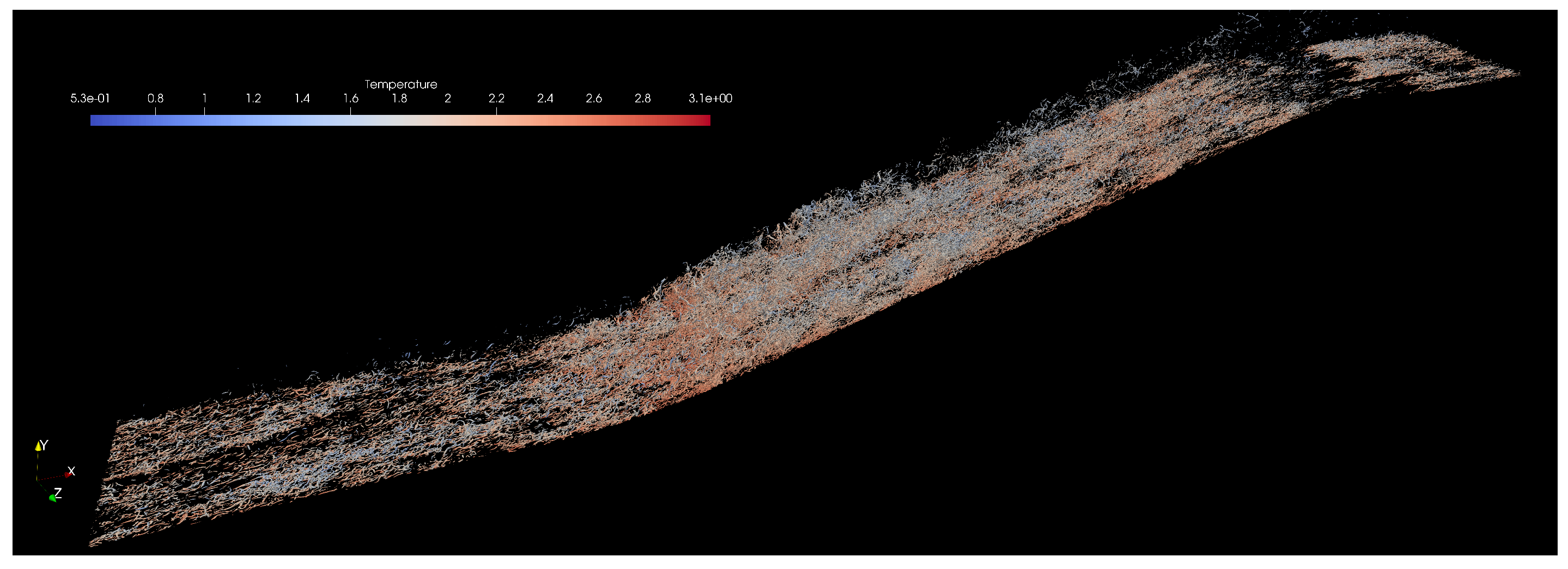
It is well known in fluid dynamics and wall-bounded flows that most of the transport of mass, momentum, and heat takes place inside boundary layers. Numerically speaking, accurately solving this thin shear layer is arduous, not to mention if the purpose is to capture turbulence, compressibility, and wall curvature effects, particularly at large Reynolds numbers and complex geometries. Furthermore, three-dimensionality and unsteadiness are “the rule, not the exception", making the boundary layer problem formidable and resource-consuming. Moreover, Direct Numerical Simulation (DNS) is a numerical tool that resolves all turbulence length and time scales in Computational Fluid Dynamics (CFD). As a consequence, it supplies the most precise spatial/temporal resolution possible of the fluid flow within the boundary or shear layer. The downside is the tremendous computational resources needed not only in the running stage of the flow solver but also during the storage and postprocessing phase [14,15]. We concern ourselves with turbulent boundary layers that evolve along the flow direction, showing a non-homogeneous condition along the streamwise direction due to turbulent entrainment (i.e., spatially-developing turbulent boundary layers, SDTBL). DNS of SDTBL requires time-dependent inflow turbulence prescription at the computational domain inlet. In this study, a method for prescribing realistic turbulent velocity inflow boundary conditions [16] is employed. The methodology has been extended to high-speed turbulent boundary layers in [14]. Furthermore, accounting for surface curvature effects induces non-trivial difficulties to the problem, since the boundary layer is subject to critical distortion due to the combined streamwise-streamline (Adverse and Favorable) pressure gradients. Figure 1 shows a lateral view of a current complex geometry (concave and convex wall curvatures) in supersonic turbulent boundary layers with 385M cells. The Reynolds number () or Von Karman number range is 900-2600, which represents a real challenge for the DNS approach. Preliminary results in Figure 1 (numerical simulation is close to the statistically steady flow stage) exhibit instantaneous fluid density contours in adiabatic walls with an evident observation (inclined line at the gray-white zone interface) of the oblique shock wave generated by the concave surface, which slows down the incoming supersonic flow (APG). In Figure 2, vortex cores are extracted and visualized via the Q-criterion methodology [7]. Clearly, at such high Reynolds numbers, the turbulence structures look finer and more isotropic. The presence of APG at the concave curvature enhances turbulence production and velocity fluctuations, as demonstrated by the high concentration of vortex cores. On the other hand, the convex curvature results in a very strong flow acceleration or Favorable Pressure Gradient (FPG) in the supersonic expansion (note the presence of expansion waves in the density contours plot). The very strong favorable pressure gradient on the incoming flow induces quasi-laminarization, [17]. It can be observed that a very low density of vortex cores exists downstream of the convex curvature.
In this manuscript, we are employing a DNS database [18] of supersonic concave-convex geometries for our augmented reality (AR) purposes. The computational domain possesses 10M cells. Three wall thermal conditions were prescribed: Cold, Adiabatic, and Hot conditions. The Reynolds number () or Von Karman number range is 214-684. Readers are referred to [10] for additional scientific visualization details.
Figure 1.
Contours of instantaneous density for the supersonic boundary layer at Mach 2.86 (flow from left to right).
Figure 1.
Contours of instantaneous density for the supersonic boundary layer at Mach 2.86 (flow from left to right).
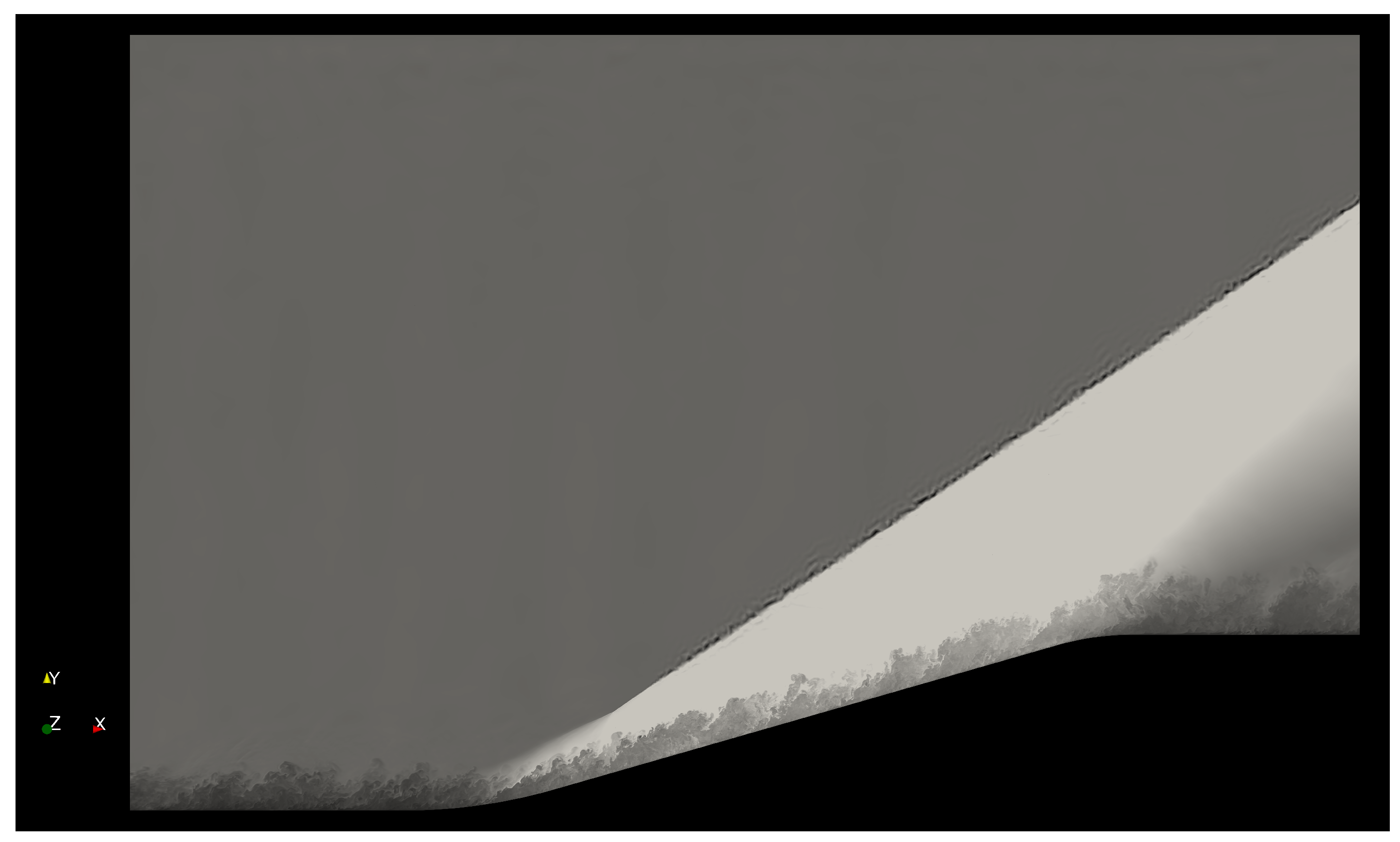
Figure 2.
Iso-surfaces of vortex cores via the Q-criterion method colored by instantaneous temperature at high Reynolds numbers.
Figure 2.
Iso-surfaces of vortex cores via the Q-criterion method colored by instantaneous temperature at high Reynolds numbers.
3. DNS Data Post-Processing for XR Visualization
Processing the large-scale simulations is a non-trivial task that demands a scalable and efficient solution. In this study, we are making use of our in-house Aquila library [15]. Aquila is a modular library for post-processing large-scale simulations, which enables large datasets by operating out-of-core and providing the illusion of an in-memory dataset through asynchronous data pre-fetching [19]. The library uses an MPI backend for distributed memory communication and HDF5 [20] for efficient and compressed files at the storage backend. Our approach to high-performance calculations requiring instantaneous flow parameters is an asynchronous dispatch engine that handles scheduling without input from the domain expert. Currently, we focus on TBB (Threading Building Blocks) as our threading layer [21,22]. TBB incorporates a non-centralized, highly scalable work-stealing scheduler amenable to unbalanced workloads. Our implementation also approaches issues such as conditional masking of flow variables via Boolean algebra, which avoids excessive memory allocations in favor of additional integer calculations. Optimizing compilers are capable of generating machine instructions accounting for the wide backends in modern CPUs and concurrent floating point/integer units in modern GPUs, taking advantage of the added integer computations. All in all, our post-processing infrastructure is scalable from platforms with constrained performance to large-scale supercomputers with thousands of CPU/GPU cores.
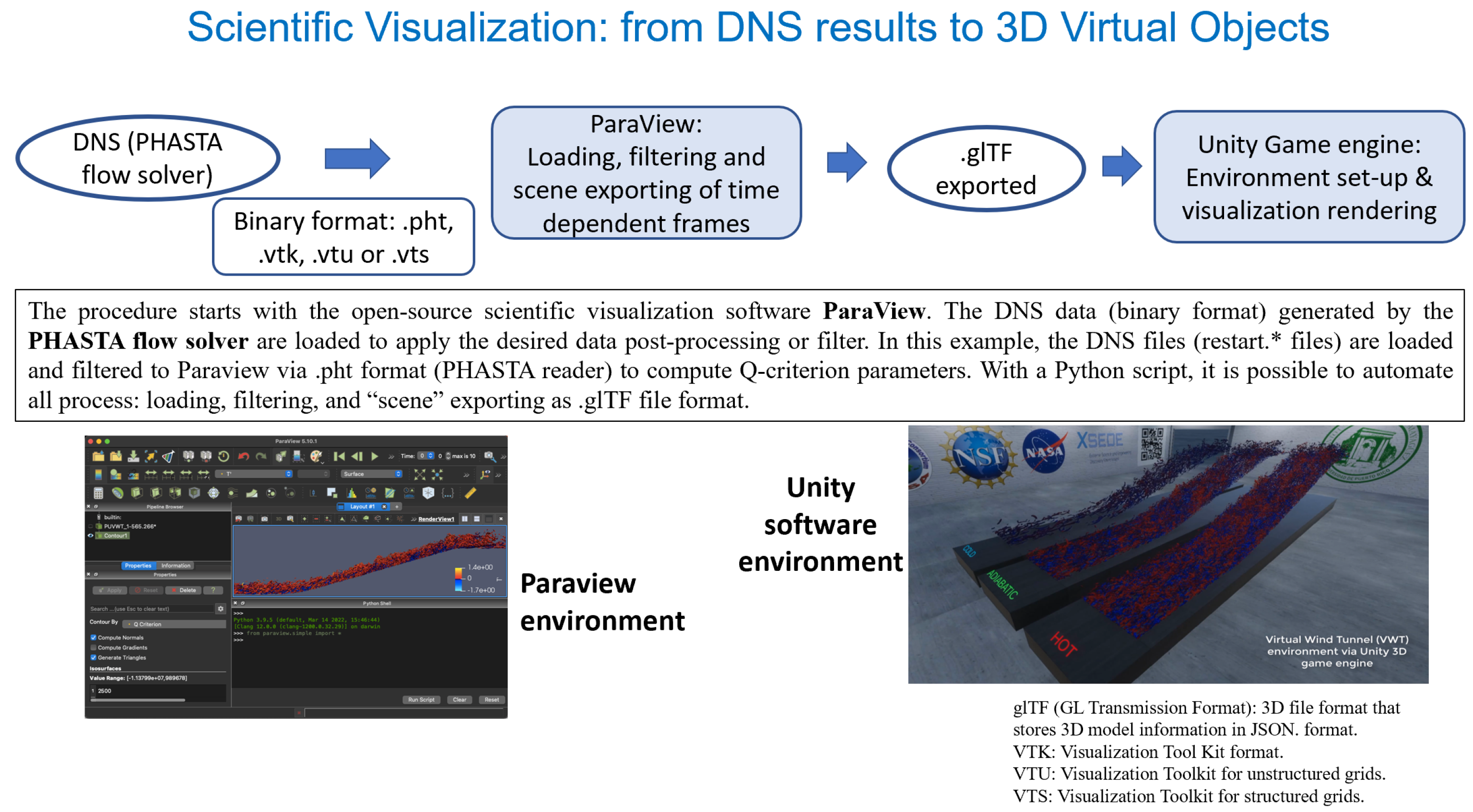
The DNS dataset size utilized in the present study at low Reynolds numbers is 736GB (approximately 4,000 volumetric flow fields). The ongoing DNS dataset at much higher Reynolds numbers is estimated to reach around 28TB by collecting 6,200 three-dimensional flow fields. Visualization of 3D database is performed by means of the modular interface VTK library [23] (.vts, .vtu or .vtk formats, including the .pht format as the PHASTA flow solver reader), which enables visualization in ParaView [24]. Figure 3 depicts the corresponding pipeline procedure from high spatial/temporal resolution data to Unity game engine rendering in our Virtual Wind Tunnel (VWT). The procedure starts with the open-source scientific visualization software ParaView. The DNS data (binary format) generated by the PHASTA flow solver are loaded to apply the desired data post-processing or filter. In the left image of Figure 3, the DNS files (restart.* files from the PHASTA flow solver) are loaded and filtered to Paraview via .pht format (PHASTA reader) to compute Q-criterion parameters. With a Python script, it is possible to automate all process: loading, filtering, and “scene” exporting as GLTF file format [10]. Once prepared, the data is imported into Unity to develop a Virtual Wind Tunnel (VWT), a virtual environment where users can visualize and interact with DNS results on-demand, offering a truly immersive experience.
The study focuses on visualizing turbulent fluid flows, specifically supersonic spatially-developing turbulent boundary layers (SDTBL), using DNS data with high spatial and temporal resolution. Exploring the use of Direct Numerical Simulation (DNS) database for visualization in augmented reality (AR) technologies, such as HoloLens Gen. 2, and Microsoft Azure as backend to alleviate local computational usage and rendering resources.
Figure 3.
Pipeline process for flow visualization in our Virtual Wind Tunnel in Unity game engine.
4. Data Optimization and Compression via GLB Encoding
We implemented a custom C# script executed in a Node.js environment using the GLTF library to merge individual GLTF frames into a single GLTF. Efficient asset preparation is essential for performance-sensitive scientific visualization, particularly when handling high-frequency real-time rendering of dense frame-based simulation output. To facilitate real-time rendering of temporally resolved flow fields in Unity, we devised a streamlined pipeline to consolidate multiple GLTF files, each representing a distinct time step, into a singular binary GLTF file suitable for optimized runtime execution.
Experiments that were conducted to evaluate the performance and memory efficiency of the GLTF and GLB formats using 40-frame simulations, focused on the Hot, Cold, and Adiabatic wall conditions. In these simulations, these three wall conditions of GLTF cases were run concurrently, resulting in average memory usage and noticeable performance fluctuations due to the separate handling of meshes, textures, and animations inherent in the GLTF format. In contrast, the GLB format, which consolidates all assets into a single binary file, exhibited superior memory management and reduced performance variance. In particular, GLB-based simulations demonstrated a significant reduction in garbage collection (GC) related spikes in profile analysis, leading to smoother and more stable system performance. Statistical analysis revealed that the GLB format achieved up to 25% memory savings in all tested cases. Specifically, the Cold wall saw a reduction of 22.84%, the Hot wall 25.23%, and the Adiabatic wall 25.00%, as shown in Table 1. These results highlight that the binary nature of GLB files not only reduces file sizes but also minimizes memory overhead and optimizes asset loading efficiency, making it a more efficient format for large-scale simulations and real-time applications. Consequently, the GLB format proves to be more effective in terms of memory usage, performance stability, and garbage collection management compared to the GLTF format.
4.1. Optimizing Scientific Visualization in Unity: Compression Strategies for GLTF to GLB
For the analysis, two separate projects were created in Unity (version 2022). Our first project used 40 individual GLTF frames for the Cold, Hot, and Adiabatic simulation situations. In this configuration, each frame was loaded and handled as an individual resource. For the second project, all 40 frames were combined into a single GLB file and converted to binary format for better asset management. The aim of this approach was to compare the performance and memory efficiency between the handling of separate GLTF files and a single GLB file during long-duration simulations. The subsequent section presents a comprehensive overview of the data compression optimization process and its impact on enhancing real-time simulation performance.
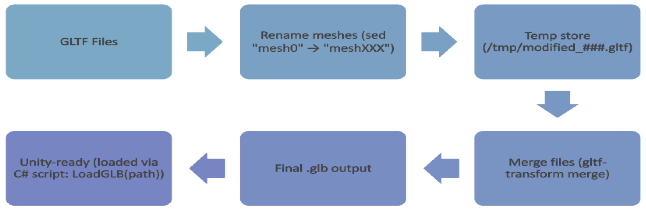
This process was automated using a Bash script (Figure 4) executed within a Linux shell environment through Windows Subsystem for Linux (WSL2), specifically Ubuntu 20.04 distribution. The script performed three critical operations: (a) the input GLTF files—each corresponding to a unique simulation frame - were deterministically sorted using lexicographic ordering based on filename indices to preserve temporal continuity, (b) automatic disambiguation of duplicate mesh identifiers - mesh objects originally labeled "mesh0" across all files were uniquely renamed (e.g., "mesh000", "mesh001", etc.) using stream editing (sed) during preprocessing, and (c) the modified assets were programmatically merged using the gltf-transform merge tool from the @gltf-transform/cli library (v3.0+) toolkit, installed via Node.js which is built on top of the GLTF 2.0 specification, and offers high-performance conversion and restructuring of GLTF assets. The script leverages mktemp to manage temporary processing directories, ensuring non-destructive input handling.
The transformation into GLB format yielded a compact binary representation that embeds geometry, material, animation, and metadata into a single, compact file. Compared to loading individual GLTF assets, this consolidation reduces filesystem I/O latency, improves Unity’s scene instantiation time, and minimizes memory fragmentation during rendering. Additionally, this approach mitigates common issues such as duplicated object names and inconsistent asset paths, which are prevalent when loading files independently in Unity’s runtime environment. However, Unity’s import limit of 2GB per asset posed a constraint. Consequently, merged GLBs were restricted to 40 frames to stay within this boundary. The resulting GLB asset encapsulates all 40 individual time-step frames, structurally arranged to support animated rendering workflows within Unity’s Scriptable Render Pipeline (SRP). This approach minimizes memory fragmentation, improves CPU-GPU transfer latency, and circumvents identifier collisions that arise when using separately imported GLTF files.
Figure 4.
C# Script Workflow for GLTF to GLB Conversion and Optimization.
Future research will focus on enhancing performance through dynamic streaming and modular asset loading techniques to further mitigate Unity’s 2GB asset import limit. Dynamic streaming will allow assets to be loaded on demand, optimizing memory usage and reducing load times, especially for larger datasets. Additionally, modular asset loading will enable selective asset loading, ensuring that only the necessary assets are loaded into memory at any given time, further improving performance and scalability. These approaches aim to address current limitations and maximize the potential of GLB for high-fidelity, resource-intensive applications. Ultimately, GLB will continue to offer substantial benefits in asset management and runtime efficiency, solidifying its position as the optimal format for complex scientific visualization tasks.
5. Unity Profiling Tools for Performance and Memory Optimization
In this section, we provide an in-depth, analysis and optimization procedure for enhancing performance and Unity’s memory usage throughout scientific visualization simulation. The study employs a multi-faceted evaluation framework, including thermal wall condition-based performance assessment over a particular interval, in-depth profiling using Unity’s Performance Profiler along with the Garbage Collector (GC) incremental being disabled, and inspection of memory consumption trends across execution timelines in Unity’s Memory Profiler. Unity offers a comprehensive profiling ecosystem to analyze and optimize the performance of real-time applications. Two critical components in this suite are the Profile Analyzer and the Memory Profiler, which enable systematic evaluation of runtime execution behavior and memory utilization.
The Profile Analyzer operates on data captured from Unity’s native Profiler and facilitates statistical analysis across multiple frames. It supports detailed inspection of CPU-intensive operations, including markers such as PlayerLoop, EditorLoop, and render pipeline stages like ExecuteRenderGraph and DoRenderLoop_Internal. By aggregating data per frame, it computes aggregate metrics such as mean, median, min, max, and standard deviation, allowing developers to identify execution hotspots, temporal anomalies, and performance regressions across test conditions. This tool is significantly effective for comparative analysis between build variants, platform targets, or rendering configurations.
The Memory Profiler provides a snapshot-based segmented breakdown of memory allocations within Unity’s execution environment. It differentiates between Tracked Memory (memory explicitly managed by Unity, considering the resource files, materials, and scripts) and Untracked Memory (memory that is not directly visible to the engine, typically from native or external sources). The profiler also reports Managed Heap statistics: Specifically, In Use (actively referenced memory) and Reserved (pre-allocated but unused heap space), as well as fragmentation and object lifecycle data based on the Graphics Drivers, Executable, and DLLs. These metrics prove to be essential for evaluating garbage collection behavior through GC (Garbage Collector) incremental, asset loading overhead, and memory retention issues.
Profiling analysis conducted across multiple configurations of our Unity-based scientific visualization project revealed ten markers that consistently contributed the highest computational load. Notably, PlayerLoop and EditorLoop—which represent the core execution cycles of runtime and editor environments, respectively—demonstrated substantial performance consumption, indicating that both play a critical role in driving the animation and scene updates of our flow visualizations. Markers associated with Unity’s High Definition Render Pipeline (HDRP), including HDRenderPipelineRenderCamera, Inl_HDRenderPipelineRenderCamera, and Inl_HDRenderPipelineAllRenderRequest, reflect the rendering intensity inherent in our project, which involves high-resolution contour animations and shader-heavy visuals. Additionally, the ExecuteRenderGraph and Inl_ExecuteRenderGraph markers, responsible for coordinating render pass execution through HDRP’s Render Graph architecture, were significant contributors to frame time, highlighting the complexity of rendering layered flow fields across multiple podiums. The presence of Inl_RecordRenderGraph further emphasizes the cost of preparing and recording these passes, particularly when rendering large GLTF/GLB assets in real time. The marker UnityEngine.CoreModule.dll!UnityEngine.Rendering underscores the low-level rendering tasks initiated by Unity’s core systems, and its high resource usage suggests shader compilation and draw call management are nontrivial in our pipeline. Finally, Profiler.FlushCounters, though not directly part of the gameplay loop, consumed measurable resources due to the profiling process itself, particularly when capturing the data per frame. Together, these markers provide critical insights into optimization targets, especially under the memory and computational constraints imposed by our use of GLTF/GLB formats and real-time streaming of scientific data.
Secondly, enabling or disabling incremental garbage collection wherever appropriate and monitoring memory allocation through Unity’s Memory Profiler can help minimize GC-related spikes. Key optimization techniques involve minimizing memory fragmentation through proper asset loading/unloading management and leveraging object pooling to reduce allocation frequency. Compression of textures, shaders and meshes, along with efficient handling of native code (including graphics drivers and DLLs), can significantly reduce memory overhead. Additionally, minimizing the memory footprint of untracked allocations, such as those from external libraries or plugins, is crucial for overall optimization. To further optimize memory usage, it is critical to monitor memory spikes during scene transitions or asset loading and to ensure that unused objects and unmanaged memory are disposed of appropriately to prevent memory leaks. Continuous monitoring of both tracked and untracked memory using Unity’s Memory Profiler enables the reduction of GC-related performance issues. The process and outcomes of these attempts to optimize simulation execution for real-time applications are described in the following phases.
5.1. Thermal Wall Conditions Based Stability Evaluation: Hot, Cold and Adiabatic
To evaluate the effect of runtime period on performance and resource usage, the flow simulations were conducted at intervals of 5, 10, and 15 minutes. Performance metrics were recorded throughout the experiment to calculate how increase in simulation per affected execution time (in milliseconds) and system stability for both long-duration formats. Results demonstrate that performance stabilizes with an increase in runtime, indicating the potential for long-duration simulations with predictable resource consumption when optimized correctly. This procedure highlighted the variations in memory handling and performance stability between the GLTF and GLB formats, particularly in extended simulation scenarios.
Preliminary profiling data derived from the Unity-based implementation reveal that the Hot wall flow scenario consistently incurs longer execution times across the majority of key computational markers when compared to the Cold and Adiabatic boundary conditions. This empirical observation aligns with established theoretical expectations in both fluid dynamics and computational visualization. Specifically, hot-wall boundary conditions promote increased flow isotropy and the development of finer-scale turbulent structures, which in turn generate more complex iso-contour topologies and elevated particle interaction densities (heavier frame files). Within the Unity environment, such flow characteristics manifest as increased computational overhead, primarily due to intensified mesh deformation, a greater number of vertex manipulations, and more frequent shader evaluations executed per frame. Furthermore, the presence of thermally induced vortical structures necessitates the instantiation of denser particle fields, thereby amplifying draw call frequency and real-time physics computation demands during animation rendering.
Such elevated complexity in simulation and visualization directly affects performance metrics like PlayerLoop, Editorloop HDRenderPipelineRenderCamera, and ExecuteRenderGraph, leading to a measurable increase in frame time and resource usage for the Hot case. The render pipeline, especially in the HDRP framework, experiences additional computational overhead when processing complex materials and lighting conditions related to thermal plumes and gradients.
Figure 5.
Comparison of mean execution times for the top 10 most resource-consuming markers across Cold, Hot, and Adiabatic flow cases over a 15-minute runtime period.
Figure 5.
Comparison of mean execution times for the top 10 most resource-consuming markers across Cold, Hot, and Adiabatic flow cases over a 15-minute runtime period.
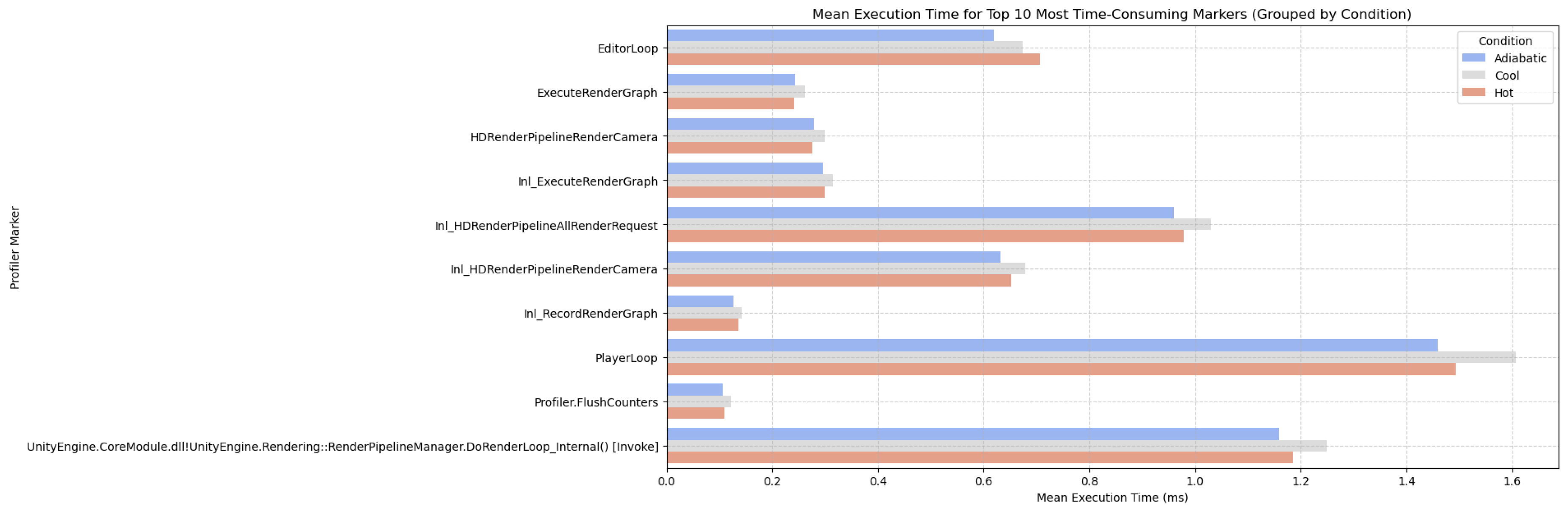
Notably, during extended runtime evaluations (e.g., 15-minute continuous execution), the Cold flow case begins to demonstrate computational resource utilization that is comparable to, or marginally exceeds, that of the Hot case for specific performance markers (Figure 5). This observed shift is principally attributable to the cumulative memory allocation patterns and asset management behaviors inherent to the Unity engine. Specifically, the increasing complexity of mesh geometries and the rendering of high-resolution contour plots in the Cold scenario progressively impose greater demands on both memory and processing subsystems. Despite this transition, the initial observation—that the Hot flow configuration incurs a higher computational load—remains significant, as it provides critical insight into the influence of thermofluidic properties (e.g., elevated temperatures and intensified turbulence) on Unity’s real-time visualization efficiency.
5.2. Profiler Based Performance Comparison: GLTF vs GLB
A profiler-based comparative analysis was conducted using Unity’s Profile Analyzer to evaluate execution performance between Unity projects utilizing individual GLTF files and a merged GLB file. Each project contained 40 frames across three thermal flow cases - Cold, Hot, Adiabatic, with simulations executed over a 15-minute interval to ensure consistent performance environment. Profiling in this procedure focused on the top 10 highly effective markers PlayerLoop, EditorLoop, HDRenderPipelineRenderCamera, Inl_ExecuteRenderGraph, and DoRenderLoop_Internal. Figure 6 presents the mean execution time comparison, showing that the GLTF-based project (blue) consistently demonstrated lower execution times compared to the GLB-based project (red) across critical render and update loops. The results highlight that the GLTF format sustains additional runtime overhead, likely due to its distributed structure, which requires multiple discrete resource loading operations, along with an increase in shader/material update costs during real-time data rendering. Whereas, the GLB format having monolithic binary structure allows more streamlined memory access and faster resource decoding, resulting in lower execution times across complex rendering and simulation stages.
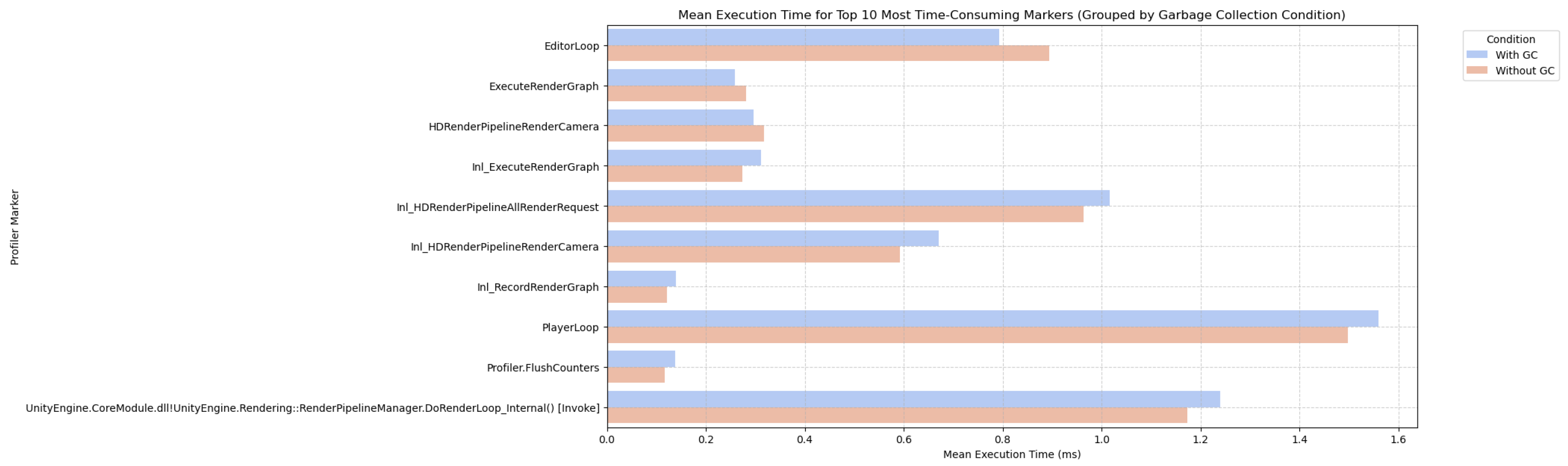
Furthermore, targeted optimizations involving Unity’s Garbage Collector (GC) configuration were evaluated to optimize memory stability during high-load simulations. Disabling incremental GC yielded a significant decrease in runtime memory spikes and improved overall simulation efficiency (Figure 7), particularly during intensive flow animations. This evaluation aimed to assess computational efficiency and determine the optimal format for large-scale scientific visualization workflows in Unity. These findings suggest that, although GLTF format remains advantageous for modular resource management, GLB, along with disabled Garbage Collector (GC) configurations, is worthier for real-time computational performance and runtime efficiency in scientific visualization workflows in Unity. To maximize performance in expansive simulations, pre-processing strategies like merging individual GLTF frames into optimized GLB assets are essential, guaranteeing improved rendering stability and decreased loading overhead without compromising on any scientific detail.
Figure 6.
Comparison of mean execution times for the top 10 most performance-consuming profiler markers across GLTF and GLB projects.
Figure 6.
Comparison of mean execution times for the top 10 most performance-consuming profiler markers across GLTF and GLB projects.
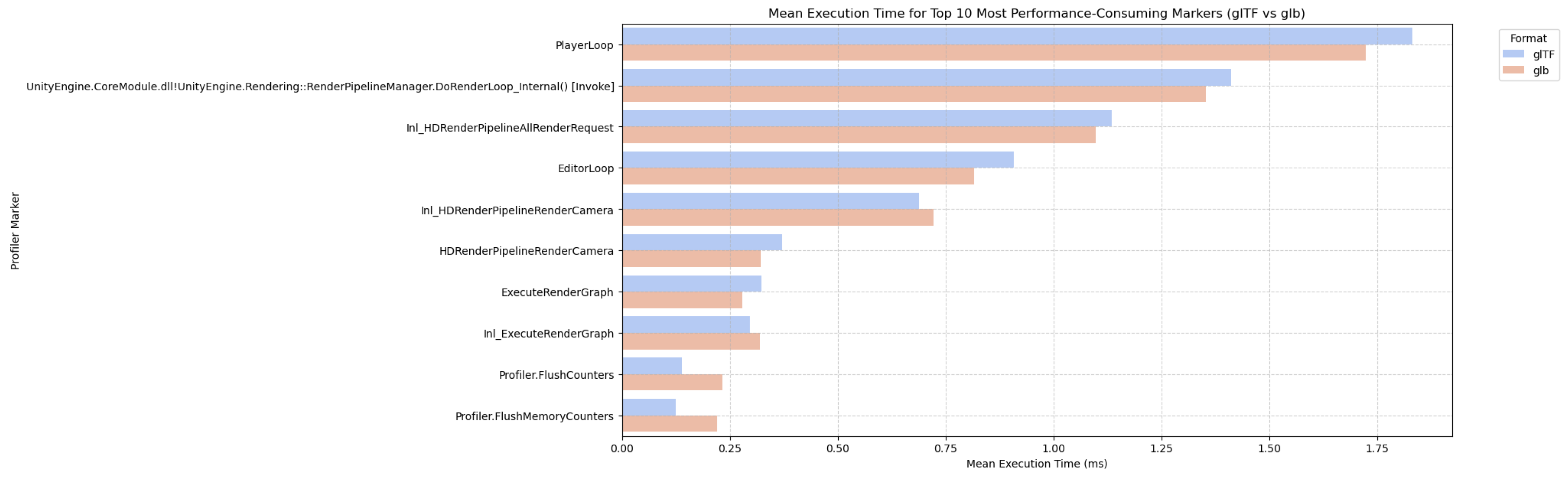
Figure 7.
Comparison of Mean Execution Times for Top 10 Markers with Garbage Collection Enabled and Disabled.
Figure 7.
Comparison of Mean Execution Times for Top 10 Markers with Garbage Collection Enabled and Disabled.
5.3. Memory Utilization Analysis for GLTF vs GLB in Scientific Visualization
In high-fidelity scientific visualization applications such as Direct Numerical Simulation (DNS) flow animations, efficient memory management plays a pivotal role in ensuring smooth runtime performance and scalability, particularly in immersive environments like virtual and mixed reality. To evaluate runtime performance and optimize resource loading along with animation, two approaches were recorded: one utilizing 40 individually loaded and animated GLTF files, and the other employing 40 merged GLB files. Both configurations were evaluated using Unity’s Memory Profiler tool during the execution of animated flow visualizations that provided quantitative insight into the distribution of memory usage between managed, tracked, and untracked segments. The goal of this experiment was to analyze the memory utilization patterns associated with each method and to determine which approach offers a more optimized memory consumption for high-volume simulation data.
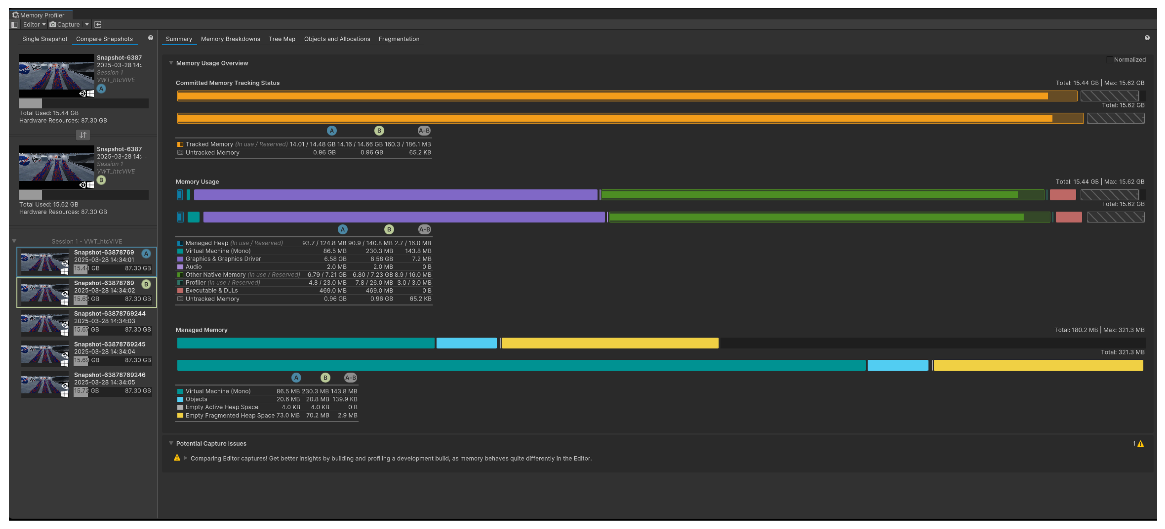
The GLTF-based project recorded a total memory usage of 17.22 GB (Figure 8), with tracked memory at 14.82 GB in use (out of 16.10 GB reserved) and untracked memory totaling 1.12 GB. In contrast, the GLB-based setup reported a lower total memory usage of 15.44 GB (Figure 9), with tracked memory at 14.01 GB (reserved: 14.48 GB) and untracked memory at 0.98 GB. This notable reduction of approximately 10.3% in total usage illustrates how binary asset consolidation in the GLB format leads to more efficient memory handling. Additionally, a lower memory reservation gap in the GLB project indicates tighter memory control, reducing fragmentation, and improving predictability.

Table 2.
Memory Consumption Metrics for 40 Individual GLTFs and 40 Merged GLB.
| Metric | 40 GLTFs (Individual) | 40 GLB (Merged) | Reduction |
|---|---|---|---|
| Total Memory Usage | 17.22 GB | 15.44 GB | 1.78 GB (10.3%) |
| Tracked Memory (In Use / Reserved) | 14.82 GB / 16.10 GB | 14.01 GB / 14.48 GB | 810 MB in use |
| Untracked Memory | 1.12 GB | 0.98 GB | 140 MB |
| Managed Heap (In Use / Reserved) | 215.6 MB / 850 MB | 93.7 MB / 124.8 MB | 121.9 MB used |
A significant difference was also observed in managed heap usage, which directly relates to the .NET runtime’s memory allocation. The GLTF version used 215.6 MB of the heap (reserved: 850 MB), while the GLB version used only 93.7 MB (reserved: 124.8 MB). This stark contrast implies higher garbage collection overhead and frequent allocations in the GLTF approach, likely due to the repetitive instantiation of metadata such as GameObjects, materials, and meshes. In contrast, the GLB strategy minimized these allocations by embedding all assets into a single reusable structure, reducing the load on the garbage collector, and improving runtime consistency.
Figure 8.
Memory Profiler Snapshot Summary for 40 individual GLTFs.
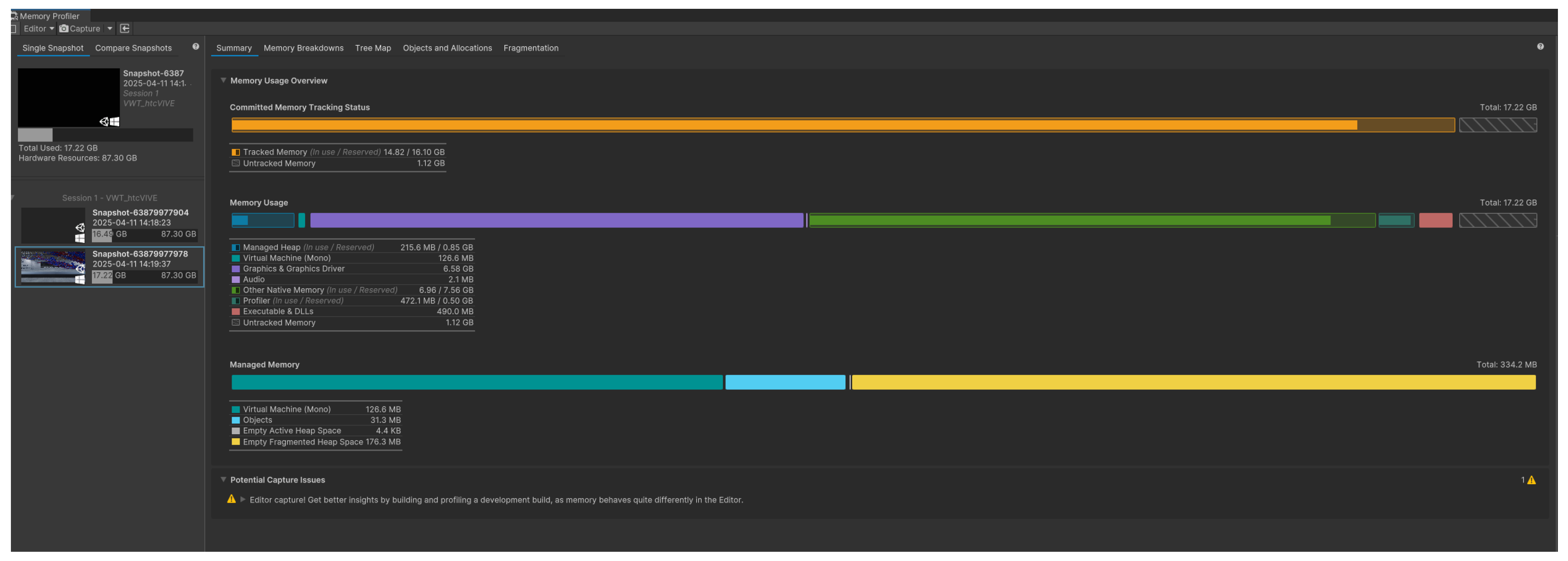
Figure 9.
Memory Profiler Snapshot Summary for 40 merged GLBs.
Ultimately, the memory profiling results clearly establishes the advantages of using merged GLB files over individually loaded GLTF assets in Unity-based DNS visualization projects as a more memory-efficient solution for large-scale, frame-by-frame scientific animations. The GLB approach offers a more compact and controlled memory profile, with a lower total memory consumption, reduced untracked allocations, and a significantly smaller managed heap footprint. These characteristics are particularly beneficial in extended reality (XR) applications, where performance constraints are tighter and memory efficiency directly impacts user experience. Consequently, adopting a GLB-based asset pipeline is recommended for scalable and immersive scientific visualizations in Unity.
In the context of our GLTF vs. GLB performance analysis, targeted memory optimization plays a critical role in reducing runtime variability and enhancing stability. Unity’s Memory Profiler revealed that GLB files, by encapsulating geometry, textures, and animations into a compact binary format, significantly reduced managed heap fragmentation compared to individually loaded GLTF assets. This consolidation minimizes per-frame memory allocations and improves asset instantiation efficiency during runtime. Major approach applicable to GLB-based workflows include aggressive texture and mesh compression, which further reduces memory footprint without sacrificing visual fidelity. The unified nature of GLB also reduces the memory overhead associated with redundant asset references and inconsistent loading paths, commonly observed in GLTF workflows. Overall, these improvements aim to reduce frame time variability, supporting measured validation of runtime performance and memory and rendering efficiency in complex immersive environments, ensuring scalable performance for large-scale scientific visualizations in Unity.
6. Remote Visualization via Microsoft Azure
A major breakthrough in the remote visualization of Direct Numerical Simulation (DNS) data, especially for fluid dynamics research, has been made using the combination of Microsoft Azure’s cloud computing capabilities with the HoloLens Gen. 2 augmented reality (AR) platform. Using Azure’s powerful computing capacity, this system processes and renders high-resolution DNS simulations in real-time. The HoloLens 2 receives the streamed images for immersive visualization. The outcomes of this configuration have shown a number of important benefits. First, supersonic spatially-developing turbulent boundary layers (SDTBL) can be seen in previously unheard-of detail because to the Virtual Machine (VM) powered by Azure, which effectively manages the processing needs of DNS simulations. Users have the opportunity to interact with the data in a completely immersive augmented reality environment on the HoloLens 2, where the simulations, produced using Unity, are smoothly delivered. This facilitates the intuitive investigation of intricate fluid flow patterns, leading to a more profound comprehension of the fundamental physical phenomena. By offloading the computationally intensive tasks to Azure, we achieved a level of detail and interactivity in the DNS simulations that would be impossible on standalone devices. The HoloLens 2 provided an intuitive interface for exploring the simulation data, allowing users to walk through and interact with complex fluid structures in a way that traditional 2D monitors or VR headsets cannot match. This capability opens up new avenues for research and analysis in CFD. Researchers can now visualize and manipulate large-scale simulations in real-time, gaining insights that were previously hidden in dense numerical data. The AR environment provided by HoloLens 2 offers a more natural and engaging way to interact with these simulations, leading to faster and more informed decision-making processes.
Figure 10.
PC Setup of the VR Lab
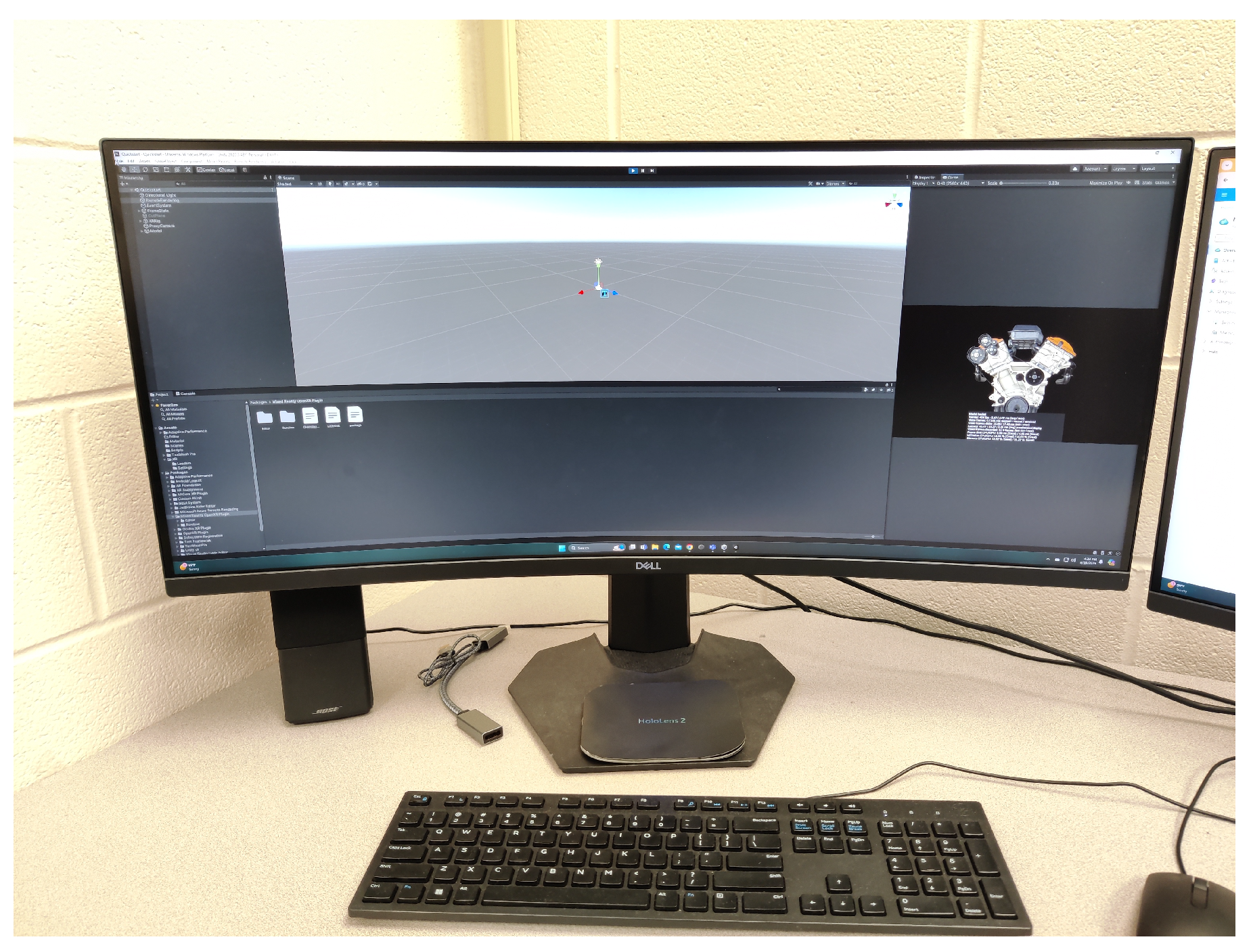
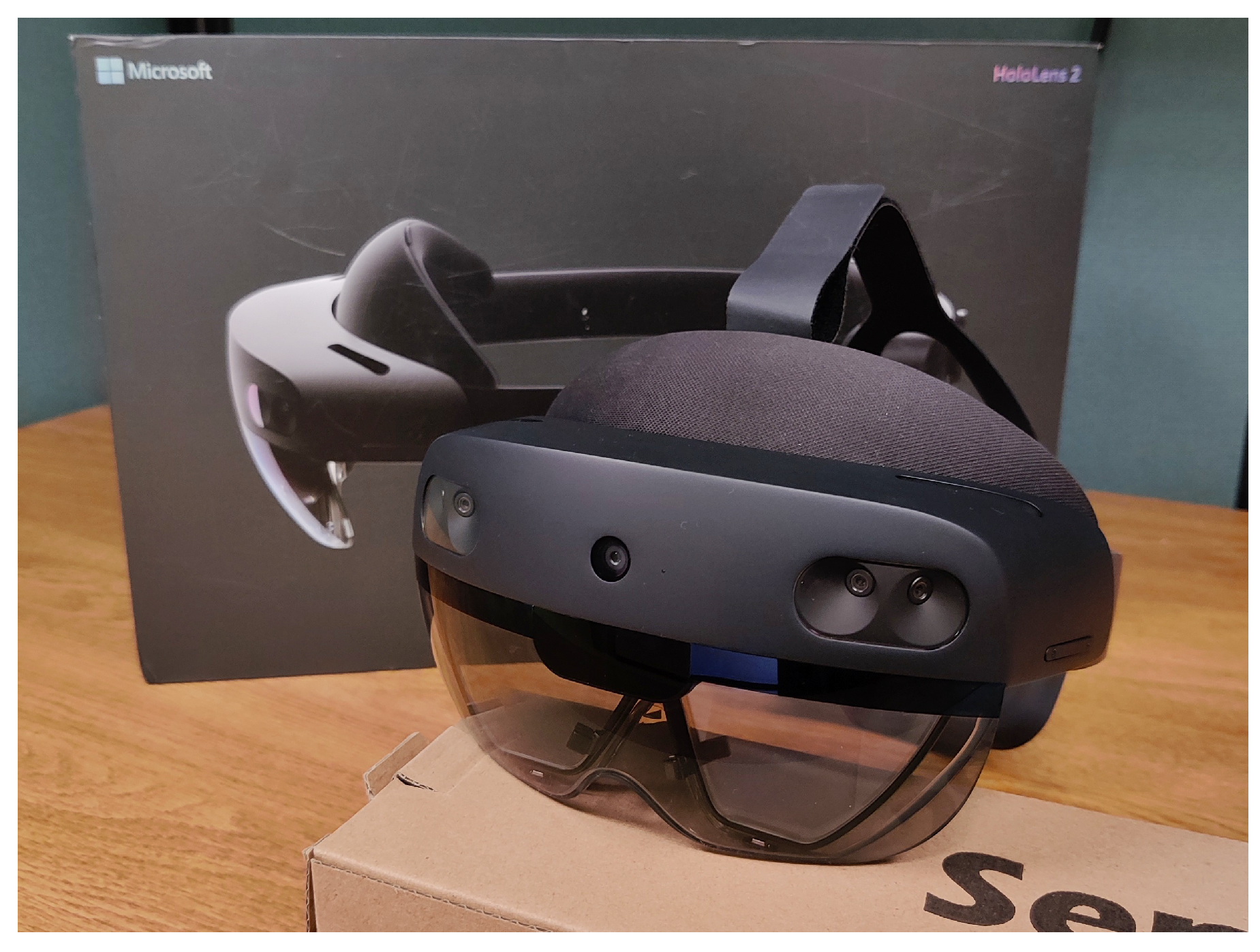
Figure 11.
HoloLens 2
6.1. Connecting Azure to HoloLens 2
The process of connecting Azure to HoloLens 2 involved several critical steps, beginning with the setup of a Virtual Machine (VM) on Azure. This VM was configured with the necessary computational resources to handle the rendering of DNS simulations. Once the VM was configured and Unity was installed, we used Azure’s remote visualization capabilities to stream the rendered output to HoloLens 2. This connection was established using a combination of Remote Desktop Protocol (RDP) and Unity’s Universal Windows Platform (UWP) build settings, which allowed us to deploy the Unity project directly to HoloLens 2. By enabling Developer Mode and Device Portal on HoloLens 2, we ensured seamless communication between the Azure VM and the AR headset. The result was a highly responsive and immersive visualization of fluid dynamics, viewed directly through the HoloLens 2.
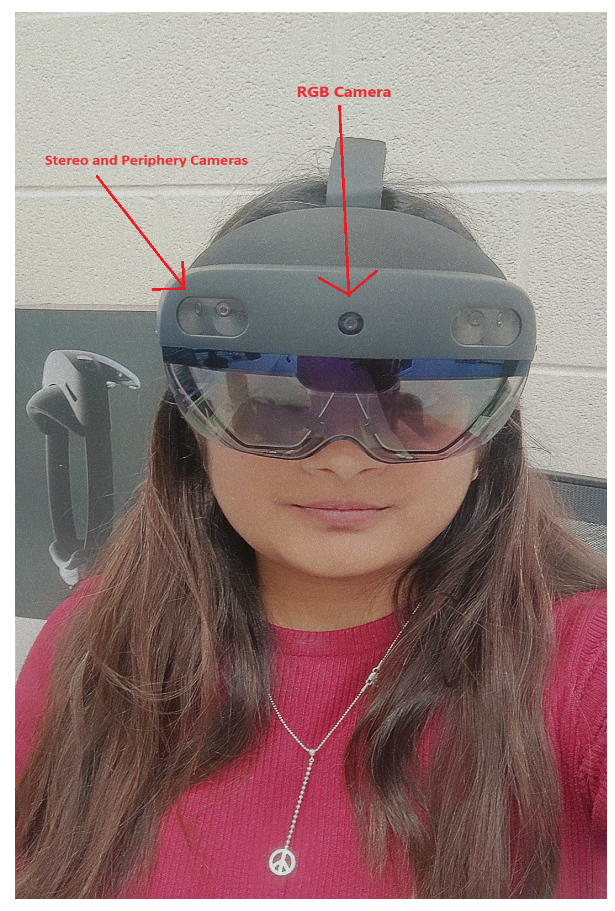
Figure 12.
The author wearing Microsoft HoloLens 2, with labels indicating the positions of the Stereo and RGB cameras.
Figure 12.
The author wearing Microsoft HoloLens 2, with labels indicating the positions of the Stereo and RGB cameras.
With the view to illustrating the application of AR using Azure Remote Rendering, and connecting it to the HoloLens 2, we followed an encompassing series of steps that involved certain software and hardware configurations. The workflow was processed on a high-performance PC with an 13th Gen Intel® Core™ i9 processor, 64 GB of RAM, and an NVIDIA GeForce RTX 4090 GPU, running Windows 11 Home. This PC served as the primary development environment, ensuring a sufficient computational power for rendering and processing of the tasks. Initially, we configured the Azure Remote Rendering service by accessing the Azure portal on this PC. A new rendering account was created, and key credentials, such as the account key and domain, were generated for secure communication between the client and Azure’s cloud services. The HoloLens 2 headset, equipped with a Qualcomm Snapdragon 850 processor, 4 GB of RAM, and running the Second-generation custom-built holographic processing unit with the storage of 64-GB, was connected to a stable 5 GHz Wi-Fi network to facilitate seamless data streaming. We then employ Unity 2021.3 LTS to develop the remote rendering application, incorporating the Azure Remote Rendering SDK and the Mixed Reality Toolkit (MRTK). The Unity project was specifically configured to support ARM64 architecture, crucial for optimal performance on the HoloLens 2. Complex 3D models which are optimized in formats like GLTF, prepared for remote rendering, ensuring high-fidelity visualization.
For the code optimization and project management, Visual Studio was used extensively. After configuring Unity, we opened the project in Visual Studio by navigating to File’s Build Settings in Unity, switching the platform to Universal Windows Platform, which generates a solution file. This solution was then opened in Visual Studio, where we adjusted the configuration to Release and ARM64, and set the debugger mode to Remote Machine. Specific settings were fine-tuned, including entering the IP address or the device name, which acts as a Machine Name of the HoloLens in the Debugger settings, and ensuring the HoloLens was connected via USB to the PC. Finally, the project was built and deployed directly from Visual Studio to the HoloLens 2 using the debugger (F5), enabling real-time testing and validation of the application.
Figure 13.
Baseline trial for Azure remote visualization, illustrating the initial setup and performance metrics for comparison with subsequent optimizations.
Figure 13.
Baseline trial for Azure remote visualization, illustrating the initial setup and performance metrics for comparison with subsequent optimizations.
This diligent setup allowed us to have a robust and responsive mixed-reality experience, with Azure’s cloud resources effectively handling the rendering load, thereby overcoming the hardware limitations of the HoloLens 2. The use of Visual Studio for optimization and deployment ensured that the application was both structured and sturdy, providing a high-quality, immersive experience that is crucial for complex data visualization tasks.
Another milestone is the scalability of the system. By leveraging Azure’s scalable cloud architecture, the simulations’ complexity may be increased without requiring the user to switch their hardware. This feature not only improves the accessibility of high-level simulations but also makes sure that a certain system can adapt to future research demands, allowing for increasingly complex and computationally demanding models. Besides, the integration with HoloLens 2 opens up new options for collaboration, research, and teaching. No matter where they are situated in the world, several people can view and work with the same simulation of the data in real-time, thanks to the AR interface. In collaborative academic environments, where the team members can engage with and confer about intricate simulations as though they were in the same room, this feature is specifically helpful. To sum up, a major advancement in computational fluid dynamics research has been achieved with the deployment of HoloLens 2 and Azure for remote DNS visualization. This method not only increases the efficacy and efficiency of data visualization but also paves the way for further advancements in cloud-based augmented reality applications. According to the research, these kinds of systems will be essential to the advancement of our understanding of fluid dynamics and other complex scientific fields.
7. Conclusions
This research presents an innovative approach for remote flow visualization, focusing on supersonic spatially-developing turbulent boundary layers (SDTBL) using DNS data within extended reality (XR) environments. By leveraging advanced data processing pipelines and tools like Unity’s Profile Analyzer, Memory Profiler, identified the top 10 performance markers. This allowed for the analysis and isolation of the most resource-intensive parameters impacting simulation performance, virtual wind tunnel interactivity, and enabling immersive exploration of complex fluid dynamics. Quantitative results showed significant improvements: GLB encoding reduced local memory usage by up to 25.00%. Via analysis using Memory Profiler, the GLB format demonstrates a clear advantage over GLTF, achieving a 10.3% reduction in total memory usage (from 17.22 GB to 15.44 GB) and lowering untracked memory by 12.5%, which improves memory predictability and reduces fragmentation during complex visualizations. Additionally, tracked memory efficiency increased by over 5%, with the GLB setup maintaining tighter memory control (14.01 GB used out of 14.48 GB reserved) compared to GLTF (14.82 GB used out of 16.10 GB reserved). When combined with the disabling of Unity’s incremental Garbage Collector, runtime memory spikes were significantly reduced, improving performance of real-time simulations and reliability. These optimizations combined make GLB with non-incremental GC the superior configuration for managing large-scale, high-frequency, frame-based visualization for complex CFD datasets in Unity. In situations where the 2GB Unity import limit is in effect, the integrated binary structure of GLB files made asset management easier and reduced Unity’s asset import overhead.
Future work will explore runtime streaming of GLB sequences and asynchronous loading to bypass Unity’s asset size limits, reducing memory pressure. This will enable the visualization of larger simulations (exceeding 500+ frames), opening the door for more immersive and scalable scientific visualization experiences with Unity. The methodology’s potential extends far beyond fluid dynamics, with applications in climate modeling, biomedical imaging, education, and more. While ongoing advancements in VR and AR technologies, we can integrate enhanced user interfaces, scalable cloud integration, and machine learning-driven optimizations. This research not only pushes the boundaries of scientific visualization but also opens new avenues for multidisciplinary collaboration, by providing powerful tools for analyzing and interpreting complex datasets from a variety of scientific domains.
In the end, this study lays the groundwork for effectively applying this strategy in mixed reality environments, transforming the way in which complex data can be visualized and processed in immersive and interactive contexts.
Author Contributions
Conceptualization, S.M., B.A., G.A. and D.P.; methodology, S.M., B.A., G.A. and D.P.; software, S.M., B.A., G.A. and D.P.; validation, S.M., B.A., G.A. and D.P.; formal analysis, S.M., B.A., G.A. and D.P.; investigation, S.M., B.A., G.A. and D.P.; resources, S.M., B.A., G.A. and D.P.; data curation, S.M., B.A., G.A. and D.P.; writing—original draft preparation, S.M., B.A., G.A. and D.P.; writing—review and editing, S.M., B.A., G.A. and D.P.; visualization, S.M., B.A., G.A. and D.P.; supervision, G.A.; project administration, X.X.; funding acquisition, G.A. All authors have read and agreed to the published version of the manuscript.
Funding
This research was funded by the National Science Foundation under grant #2314303. This material is based on research sponsored by the Air Force Office of Scientific Research (AFOSR) under agreement number FA9550-23-1-0241. This work was supported in part by a grant from the DoD High-Performance Computing Modernization Program (HPCMP).
Institutional Review Board Statement
Not applicable.
Conflicts of Interest
The authors declare no conflicts of interest.
References
- Bednarz, T.; Tobia, M.; Nguyen, H.; Branchaud, D. Immersive Analytics using Augmented Reality for Computational Fluid Dynamics Simulations. In Proceedings of the 17th International Conference on Virtual-Reality Continuum and its Applications in Industry; 2019; pp. 1–2. [Google Scholar] [CrossRef]
- Mendoza-Ramírez, C.E.; Tudon-Martinez, J.C.; Félix-Herrán, L.C.; Lozoya-Santos, J.d.J.; Vargas-Martínez, A. Augmented Reality: Survey. Applied Sciences 2023, 13, 10491. [Google Scholar] [CrossRef]
- Rauh, P.; Benk, C.; Beyersdorf, F.; Russe, M. Determination of local flow ratios and velocities in a femoral venous cannula with computational fluid dynamics and 4D flow-sensitive magnetic resonance imaging: A method validation. Artificial Organs 2021, 45, 506–515. [Google Scholar] [CrossRef] [PubMed]
- Yan, J.; Kensek, K.; Konis, K.; Noble, D. CFD Visualization in a Virtual Reality Environment Using Building Information Modeling Tools. Buildings 2020, 10, 229. [Google Scholar] [CrossRef]
- Chivers, T. Estimating Particle Velocity from Dual-Camera Mixed Reality Video Images Using 3D Particle Tracking Velocimetry. PhD Thesis, The University of Vermont, 2023; p. 93. [Google Scholar]
- Unity Technologies. Unity User Manual (2023.3); Version 2023.3; 2025. [Google Scholar]
- Hunt, J.C.R.; Wray, A.A.; Moin, P. Eddies, streams, and convergence zones in turbulent flows. In Proceedings of the Studying Turbulence Using Numerical Simulation Databases, 2 December 1988; pp. 193–208. [Google Scholar]
- Lin, J.R.; Cao, J.; Zhang, J.P.; van Treeck, C.; Frisch, J. Visualization of indoor thermal environment on mobile devices based on augmented reality and computational fluid dynamics. Automation in Construction 2019, 103, 26–40. [Google Scholar] [CrossRef]
- Pareja-Corcho, J.; Moreno, A.; Simoes, B.; Pedrera-Busselo, A.; San-Jose, E.; Ruiz-Salguero, O.; Posada, J. A Virtual Prototype for Fast Design and Visualization of Gerotor Pumps. Applied Sciences 2021, 11, 1190. [Google Scholar] [CrossRef]
- Paeres, D.; Lagares, C.; Craig, A.B.; Araya, G. Visualization of turbulent events via Virtual/Augmented Reality. Journal of Flow Visualization and Image Processing 2023, 31, 1–22. [Google Scholar] [CrossRef]
- Bhatia, N.; Matar, O.K. Learning and Teaching Fluid Dynamics using Augmented and Mixed Reality. In Proceedings of the 2022 IEEE International Symposium on Mixed and Augmented Reality Adjunct (ISMAR-Adjunct); 2022; pp. 865–869. [Google Scholar] [CrossRef]
- Gan, V.J.L.; Liu, T.; Li, K. Integrated BIM and VR for Interactive Aerodynamic Design and Wind Comfort Analysis of Modular Buildings. Buildings 2022, 12, 333. [Google Scholar] [CrossRef]
- Soliman, M.; Pesyridis, A.; Dalaymani-Zad, D.; Gronfula, M.; Kourmpetis, M. The Application of Virtual Reality in Engineering Education. Applied Sciences 2021, 11, 2879. [Google Scholar] [CrossRef]
- Araya, G.; Lagares, C. Implicit subgrid-scale modeling of a Mach-2.5 spatially-developing turbulent boundary layer. Entropy 2022, 24, 555. [Google Scholar] [CrossRef] [PubMed]
- Lagares, C.; Rivera, W.; Araya, G. Scalable Post-Processing of Large-Scale Numerical Simulations of Turbulent Fluid Flows. Symmetry 2022, 14, 823. [Google Scholar] [CrossRef]
- Araya, G.; Castillo, L.; Meneveau, C.; Jansen, K. A dynamic multi-scale approach for turbulent inflow boundary conditions in spatially evolving flows. Journal of Fluid Mechanics 2011, 670, 518–605. [Google Scholar] [CrossRef]
- Saltar, G.; Araya, G. Reynolds shear stress modeling in turbulent boundary layers subject to very strong favorable pressure gradient. Computers & Fluids 2020, 202, 104494. [Google Scholar] [CrossRef]
- Araya, G.; Lagares, C.; Jansen, K. AFOSR 2022: Effects of wall curvature on hypersonic turbulent spatially-developing boundary layers. In Proceedings of the 2022 AFOSR/ONR/HVSI Annual High-Speed Aerodynamics Portfolio Review; 2022; p. 19. [Google Scholar] [CrossRef]
- Lagares, C.J.; Rivera, W.; Araya, G. Aquila: A Distributed and Portable Post-Processing Library for Large-Scale Computational Fluid Dynamics. AIAA SciTech 2021. [Google Scholar] [CrossRef]
- The HDF Group. Hierarchical data format version 5, 2000-2010.
- Pheatt, C. Intel® Threading Building Blocks. J. Comput. Sci. Coll. 2008, 23, 298. [Google Scholar]
- Malakhov, A.; Liu, D.; Gorshkov, A.; Wilmarth, T. Composable Multi-Threading and Multi-Processing for Numeric Libraries. In Proceedings of the Proceedings of the 17th Python in Science Conference; Akici, F., Lippa, D., Niederhut, D., Pacer, M., Eds.; 2018; pp. 18–24. [Google Scholar] [CrossRef]
- Schroeder, W.; Martin, K.; Lorensen, B. The Visualization Toolkit; Kitware, 2006. [Google Scholar]
- Henderson, A. ParaView Guide, A Parallel Visualization Application; Kitware Inc., 2007. [Google Scholar]
Table 1.
Memory usage comparison between 40 GLTFs and merged GLB formats.
| Case | 40 GLTFs (GB) | 40 GLB - merged (GB) | Reduction (%) |
|---|---|---|---|
| Cold | 1.11 | 0.85 | 22.84 |
| Hot | 2.22 | 1.66 | 25.23 |
| Adiabatic | 1.92 | 1.44 | 25.00 |
Disclaimer/Publisher’s Note: The statements, opinions and data contained in all publications are solely those of the individual author(s) and contributor(s) and not of MDPI and/or the editor(s). MDPI and/or the editor(s) disclaim responsibility for any injury to people or property resulting from any ideas, methods, instructions or products referred to in the content. |
© 2025 by the authors. Licensee MDPI, Basel, Switzerland. This article is an open access article distributed under the terms and conditions of the Creative Commons Attribution (CC BY) license (http://creativecommons.org/licenses/by/4.0/).
Copyright: This open access article is published under a Creative Commons CC BY 4.0 license, which permit the free download, distribution, and reuse, provided that the author and preprint are cited in any reuse.


