
Submitted:
27 May 2025
Posted:
28 May 2025
You are already at the latest version
Abstract
An effect of temperature and strain rate during the hot rolling process on microstructural evolution in fine-grained Ni3Al intermetallic alloy doped with Zr and B was examined in this work. The hot rolling process was carried out at initial temperature range of 1000, 1100 and 1280C and at the strain rate between 3.9x101 s1 and 2.5 s1. The results of EBSD microstructural analyses revealed that dynamic recrystallization phenomena are initiated at the rolling temperature of 1100C, while a fraction of dynamically recrystallized grains further increases with both rising temperature and strain rate of the deformation process. Furthermore, to estimate heat losses during the hot rolling processing, a non-stationary heat transfer model was formulated and then used to evaluate experimentally received data.
Keywords:
Ni3Al-based intermetallic alloy
; hot rolling
; dynamic recrystallization
; EBSD analysis
; heat conduction model
1. Introduction
Ni3Al-based intermetallic alloys demonstrate superior characteristics compared with conventional heat-resistant nickel-based superalloys, including significantly higher strength at elevated temperature, relatively lower density, and improved resistance to corrosive environments. An analysis of the properties of these materials and their commercialization potential has been extensively presented by Sikka et al. [1,2], Jozwik et al. [3] and as well as Jarosz et al. [4], Sahare et al. [5], Sun and Yuan [6] and Tiwari et al. [7]. Their findings indicate that Ni3Al intermetallics in bulk form are predominantly utilized in the fabrication of dies and press tool components, equipment for furnaces used in thermochemical treatment, and jet engine components. Considering the aforementioned unique physical and chemical properties of these materials, their potential applications in a form of strips or foils in various advanced components, including electromechanical systems (such as heat exchangers, reactors, actuators, and glucose sensors), solar cells, automotive and aircraft engine components, and thermocatalytic systems, have been proposed.
One possible approach to obtain Ni3Al strips and foils with enhanced strength and ductility is a hot plastic processing. Notably, the literature contains limited information regarding the hot-working of Ni3Al-based intermetallic alloys. Furthermore, the available studies are limited to only a few research examples related to the hot processing of bulk materials (i.e., samples with a dimension of at least 8 mm). The studies under consideration include isothermal compression tests (Wang et al.[8], Wu et al. [9], Zhong et al. [10] and [11], Prasad et al. [12]); hot extrusion (Guo et al. [13], Sheng et al. [14]); compression tests with heated swages, and rotary working tests with localized heating evoked by friction (Schindler et al. [15] and [16]). The results mentioned in the papers indicate that appropriately selected parameters of the deformation process (temperature, strain rate and degree of deformation, state of the initial structure, and a presence of alloying elements) lead to microstructural changes in Ni3Al-based alloys as a result of dynamic recrystallization (DRX) or post-dynamic recrystallization. As it has been observed by Bhatia [17] and Ponge et al. [18], the DRX of Ni3Al-based alloys can result in the presence of the “necklace structure” characterized by fine recrystallized grains surrounding large primary grains of γ’ phase. Such a structure can play a pivotal role in achieving the desired combination of high creep and low-cycle fatigue resistance. Despite these advances, the impact of specific hot deformation parameters on the microstructural evolution and mechanical properties of Ni3Al-based alloys remains insufficiently understood, particularly for the materials in the form of thin strips or foils.
The main objective of this study was to analyze the DRX-induced microstructural changes in Ni3Al-based intermetallic strips. Because of the significantly limited dimensions (thickness of approximately 1 mm), it should be assumed that the proposed hot plastic processing will occur under conditions of intensive heat exchange between the treated material strips and the working tools (rollers).
An additional aspect of this study is to explore the possibility of obtaining transient strengthening states of Ni3Al-based alloys with the level of mechanical properties controlled by the occurrence of the necklace structure obtained by hot rolling.
2. Experimental Procedure
The hot rolling process was performed on Ni3Al-based intermetallic alloy strips with a chemical composition of Ni–22.1Al–0.26Zr–0.1B (at.%) with using rolling mill sexto. The material in the initial state (a strip of 150 x 30 x 1.12 mm) was obtained by consecutive cold rolling and heat treatment (with strictly selected conditions of deformation and recrystallization) to obtain a single-phase fine-grained structure (grain size of d~30 µm) of the γ’ phase. Details of Ni3Al strips production process were reported previously by Jóźwik et al. [19,20,21]. Such obtained material constituted the “initial” state for the hot rolling. The processing was carried out by pre-heating the Ni3Al-based strips to 1000 °C, 1100 °C or 1280 °C. Various strain rate values were applied: 3.9x10⁻¹ s−1, 9.9x10⁻¹ s−1, 1.5 s−1 or 2.5 s−1 (the last one was not used for T=1280 °C). For all hot-rolling conditions, the total strain value (i.e., expressed as a relative thickness reduction) was 0.3, and it was set in one pass. To eliminate the possibility of post-dynamic recrystallization in the material, after each hot rolling operation, the samples were immediately (in less than 1 second) cooled in a water bath. Then, an electric discharge machining was used to cut the obtained strips in a plane perpendicular to the rolling direction located in the middle of the length of the rolled material. Metallographic cuts were ground on SiC papers, and mechanically polished using diamond suspensions of 3 µm and SiO2 suspension of 0.1 µm. Microstructural studies were performed by using Quanta 3D FEG scanning electron microscope (SEM) equipped with a electron backscattered diffraction detector (EBSD) at an accelerating voltage of 20 kV, beam current of 8 nA, and analysis step (depending on magnification) from 1 µm to 0.1 µm.
Based on the results of systematic EBSD mapping of crystallographic orientations, the grain structure of polycrystalline strips was reconstructed, reviling positions of high– and low–angle grain boundaries, simultaneously. In turn, the maps of the surface distribution of the poles of the mean crystallographic orientation of individual grains Inverse Pole Figure (IPF) maps were the basis for assessing the presence of privileged crystallographic orientation and possible micro-texture. The analysis of structural changes as a result of the performed hot rolling procedures was based on the measurements of the degree of local disorientation of the crystal lattice in the volume of individual grains, presented in the form of Grain Orientation Spread (GOS) parameter maps. In this study, the average GOS parameter, which shows the average value of disorientation of the particular investigated area, was used. The analysis of the quality of the Kikuchi lines, thereby determining the Image Quality (IQ) parameter, was also performed. The primary source of imperfections in the measurements of the GOS and IQ parameters is the dependence of the test results on factors related to both the measurement parameters used and the quality of preparation. Therefore, during the sample preparation and testing, special attention was paid to maintaining the repeatability of the applied experimental conditions [22,23,24,25,26].
Finally, hardness measurements were performed in the rolling plane using the Rockwell method (HRB), with a 1/16 inch ball and a load of 100 kg, and the average value and standard deviation were determined based on at least ten measurements for each tested material variant.
Additionally, to estimate the temperature changes of the Ni3Al strips during hot rolling, a model of non-stationary heat conduction in a hot-rolled metal plate was formulated using the Comsol/FEM (Finite Element Method) calculation package (more details are show elsewhere [27]). This section may be divided by subheadings. It should provide a concise and precise description of the experimental results, their interpretation, as well as the experimental conclusions that can be drawn.
3. Results and Discussion
The examined Ni3Al-based intermetallic alloy in the initial stage (before the hot rolling) exhibited a single-phase, fine-grained γ’ secondary solid solution structure (Figure 1). The results of EBSD analyses revealed the following features: (i) a dominant (approximately 95%) fraction of high angle grain boundaries (with a disorientation angle greater than 15° between neighbouring grains) (Figure 1a), (ii) no visible crystallographic texture (Figure 1b) and (iii) a very low value of the GOS parameter (internal Grain Orientation Spread ≤1°), which is specific for a fully recrystallized material (Figure 1c).
The GOS parameter (expressed in angular degrees) measures a scattering of the crystal lattice misorientation inside a individual grain. This parameter assumes that a plastic deformation in a metallic polycrystalline material is assisted by local changes of the crystal lattice orientation in the volume of each individual grains. This crystal lattice evolution is necessary to maintain the cohesion along grain boundaries of a material subjected to a plastic deformation. For thermally activated processes (i.e., recovery and recrystallization) this parameter enables a quantitative assessment of the extent of these processes, as presented by Schwartzer et al. [28], Conde et al. [29] and Esin et al. [30]. In a polycrystalline structure, grains with a very low fraction of structural defects (typically after the recrystallization process, as in the case of the analysed alloy in the initial state) show negligible differentiation of local crystallographic orientations and the value of the GOS parameter is ≤1°. In turn, deformed grains with a high density of crystal defects show a high value of internal misorientation and, therefore, a high value (GOS>1°) of this parameter.
The IQ parameter expresses a strong relationship between the degree of crystal structure defects (e.g., as a result of plastic deformation) and the quality (blurring) of the backscattered electron diffraction lines. The electron beam interacting with the surface layer of the sample is dispersed on the crystal lattice’s defects, and the crystal planes’ curvatures are “bent” due to plastic deformation. Consequently, the diffraction lines obtained from the subareas with a high density of lattice defects are blurred and visible as dark. According to Ku [22] and Alam et al. [31], IQ values can be correlated with the dislocation density, thereby providing a means of quantifying the internal strain energy and residual stress within a material. This correlation can be particularly valuable for understanding the effects of thermal treatments and mechanical processing on material properties [32].
Hot rolling of the Ni3Al-based alloy to a strain value of 0.3 has a noticeable effect on both the microstructure (Figure 2, Figure 3, Figure 4, Figure 5, Figure 6 and Figure 7) and hardness (Figure 8) of the tested material, depending on the applied temperature and the strain rate. The results of EBSD analyses (compare Figure1 and Figure 2 and Figure 3) showed a limited extent of structural reconstruction. A comparative assessment of the GOS parameter for the material after the hot rolling showed a noticeable increase of its value compared to the starting material (the non-deformed one), with the presence of grains exhibiting a GOS >10° (compare Figure1c, Figure 2a,c,e, and Figure 3a,c,e).
The quantitative evaluation of the averaged GOS parameter values clearly shows the impact of the rolling parameters on the extent of the structural reconstruction (Figure 4a). A much more significant influence of the deformation temperature was observed in the relation to strain rate. For the hot rolling process carried out at the high strain rate ( ≥ 1.5 s−1), a similar tendency was observed. An almost linear dependence of the average GOS value on temperature was obtained (Figure 4a). The influence of a high strain rate on the course of DRX is also indicated by the analysis of the IQ parameter - for the value ≥ 1.5 s−1 - increased almost linearly with the deformation temperature (Figure 4b). The IQ parameter value did not show a significant dependence on temperature due to the hot rolling at a strain rate of 3.9x10⁻¹ s−1, and the observed changes were insignificant (approximately 3%).
=3.9x10⁻¹ s−1 at the initial temperature of: (a,b) 1000 °C, (c,d) 1100 °C, (e,f) 1280 °C.
=2.5 s−1 at the initial temperature of: (a,b) 1000 °C, (c,d) 1100 °C and at strain rate of =1.5 s−1 at temperature of 1280 °C – (e,f).
The results of more detailed EBSD analyses carried out by using higher magnifications revealed the locally occurring effects of thermally activated processes with intensity dependent on the values of the applied processing parameters (Figure 5, Figure 6 and Figure 7). The material deformed at T=1000 °C with a strain rate of 3.9x10⁻¹ s−1 (Figure 5a,b) did not show a presence of structural features that are typical for the DRX.
Increasing the strain rate at this temperature resulted in the growing fraction of very fine DRX grains (Figure 5). A serration of primary grain boundaries was observed (Figure 5c,d) in the sample hot-rolled at T=1000 °C and at a strain rate of 2.5 s−1. Analogous observations were reported by Ponge et al. [18], Sakai et al. [33] and Koundinya et al. [34], according to whom such structural features are specific for a deformation temperature lower than the critical temperature for initiating the dynamic recrystallization process. The serration of grain primary boundaries was also observed after the hot rolling at T=1100 °C and at a strain rate of 9.9x10⁻¹ s−1.
Therefore, an increase in the initial strip temperature (up to 1100 °C) promotes the formation of new grains by the DRX in sites with the highest stress concentration, i.e., the triple-junctions of grain boundaries (Figure 6), as well as along the straight segments of primary grain boundaries. The share of grain boundary segments affected by the DRX increased with increasing the strain rate, which was also reflected in the observed decrease in the strain strengthening (Figure 8).
of: (a, b) 3.9x10⁻¹ s−1 and (c, d) 2,5 s−1.
of: (a) 3.9x10⁻¹ s−1and (b) 2,5 s−1.
After the hot rolling at T=1280 °C, the material showed the largest share of DRXed grains both in the triple-junction grain boundaries and along the primary grain boundaries (Figure 7b). As reported by Bhatia et al. [17], the tendency to form necklace structures in the Ni3Al-based alloys, is caused by the tendency of planar slip and difficulty of cell formation inside the grains. Karnthaler et al. [35], Kruml et al. [36], and Wang et al. [37] have classified the Ni3Al-based alloys as high stacking fault energy (SFE of approximately 240 mJ/m2) materials. However, the results of studies by Jozwik et al. [19,21] and Polkowski et al. [38] indicate that the behaviour of materials from this group under plastic deformation conditions and subsequent thermally activated processes is more similar to that of low SFE materials, as they are characterized by intensive strain hardening (resulting from hindered transverse slip of screw dislocations and a tendency to form flat stacking of dislocations on obstacles). Furthermore, as it has been shown by Schindler et al. [15,16] the low SFE of Ni3Al-based alloys decreases a susceptibility to the DRX. Consequently, a higher strain concentration at grain boundaries is obtained leading to the DRX into the necklace structure. Such a microstructure rebuilding, which is very similar to the model presented by Ponge et al. [18], was observed in the material after the hot-rolling at a strain rate =1.5 s−1 (Figure 7b).
of: (a) 3.9x10⁻¹ s−1 and (b) 1.5 s−1.
Regardless of the applied hot-rolling process parameters, the deformed material showed a significant increase in hardness as compared with the initial material, resulting from the increased stored deformation energy (Figure 8). Regardless of the applied hot rolling temperature, the increase in the strain rate resulted in a decrease in the strain hardening of the material. It was mostly visible in the case of the process conducted at the highest strain rate (i.e., 2.5 s−1). The obtained results correspond to the discussed changes in the EBSD examined microstructure (Figure 2, Figure 3, Figure 4, Figure 5, Figure 6 and Figure 7). In other words, the microstructural evolution is dominated by a dynamic recovery process with the DRX limited to some micro-areas. As the dynamic recovery, creates low-energy dislocation systems (polygonal walls and subgrains), it effectively contributes to a reduction of the total energy stored.
The presently obtained results show that under the applied experimental conditions, a higher strain rate favours the microstructure evolution by both the DRX and dynamic recovery. This unusual relationship is probably due to the very low heat storage of the rolled Ni3Al strips, that is, the initial thickness was 1.12 mm (for comparison, the smallest dimension of Ni3Al samples analyzed in the literature is 8 mm), which, in combination with cold work rolls, resulted in greater heat losses, leading to a significant reduction in the actual material temperature during the deformation process. Consequently, a higher strain rate corresponded to relatively higher process temperature.
To estimate the possible temperature changes of the Ni3Al strips during the hot-rolling, as well as to verify the obtained research results, a non-stationary model of heat conduction in a hot-rolled metal plate, was formulated.
Regardless of the applied hot-rolling process parameters, the deformed material showed a significant increase in hardness as compared with the initial material, resulting from the increased stored deformation energy (Figure 8). Regardless of the applied hot rolling temperature, the increase in the strain rate resulted in a decrease in the strain hardening of the material. It was mostly visible in the case of the process conducted at the highest strain rate (i.e., 2.5 s−1). The obtained results correspond to the discussed changes in the EBSD examined microstructure (Figure 2, Figure 3, Figure 4, Figure 5, Figure 6 and Figure 7). In other words, the microstructural evolution is dominated by a dynamic recovery process with the DRX limited to some micro-areas. As the dynamic recovery, creates low-energy dislocation systems (polygonal walls and subgrains), it effectively contributes to a reduction of the total energy stored.
and initial temperature of stock on Brinell hardness of Ni3Al-based strips (average values).
A non-Stationary Heat Conduction Model in a Strip
The primary purpose of the modelling was to qualitatively determine the temperature changes. For this purpose, the issue was simplified to a model of heat source moving across the surface of the component. Thus, a contact surface having a linear dimension d, was set as the source of heat and at the same time - the heat receiver (Figure 9).
To determine the temperature changes and strain distribution, the presence of the following phenomena were analysed [39]: (i) the heat conduction in the workpiece to be deformed (i.e., the Ni3Al strip); (ii) convective and radiative heat losses from the workpiece surface to the environment; (iii) the heat conduction in the machining tool (roller); (iv) a contact heat transfer resistance between the workpiece and the tool; (v) a friction between the workpiece and the roller surface contributing to the surface heat source; (vi) an elastic deformation of the workpiece; (vii) a plastic deformation constituting volumetric heat sources, (viii) elastic relaxation of the material as it comes off the roller, and (ix) a change in the relative velocity of movement of the workpiece and the roller due to deformation. In the presented simplified model of a moving heat source, only the phenomena (i) – (iv) were directly taken into account. A phenomenon that is usually overlooked at this stage of simplification is the volumetric shrinkage caused by a thermal expansion.
The relatively large value of the ratio of the wafer width to its thickness provides a justification for adopting a simplified two-dimensional heat conduction model. A geometrical scheme of the model is illustrated in Figure 9.
Thus, the issue was reduced to a two-dimensional model of a non-stationary heat transfer in a plate having dimension of 195 mm × 0.56 mm, subjected to surface moving heat source (surface a in Figure 9) [42]. A symmetry condition in the plane containing the Ox axis was assumed (surface b in Figure 9), while convection and radiation losses were considered for other surfaces (surface c in Figure 9). Due to the lack of data on the constitutive model, the volumetric heat sources accompanying plastic deformation, as well as the surface frictional heat source, were omitted. An evaluation of the literature data shows that despite the noticeable impact of these effects, they do not play a dominant role in shaping the temperature distribution at a relatively high initial temperature of the hot-machined workpiece (i.e., Ni3Al strip).
The mathematical equations describing the considered model (in the Oxy coordinate system, Figure 9), are as follows:
- equation for transient heat conduction:
- initial homogeneous condition:
- boundary condition for the adiabatization of the horizontal center symmetry surface of the plate (surface marked as “b” in Figure 9):
- boundary conditions of convective and radiative heat loss (surfaces marked “c” in Figure 9, “n” is a normal direction to surfaces c):
- the displacement contact zone is modelled by the additional contact loss (surface marked as “a+c” in Figure 9) of the plate surface with the surface of the cylinder at ambient temperature, with the value of the thermal contact resistance rcont:
The last boundary condition was applied in a superposition with equation (4). The equation describes a contact with the cylinder surface excluding radiation losses and convective losses. On the other hand, in the considered case, these losses account for only approximately 2% of the losses caused by a heat transfer through the contact zone. Because determination of the value of thermal contact resistance is subjected to a larger error, and because of the need for computational optimization of the numerical model, the arrangement of conditions (4) and (5) remained unchanged.
Numerical Model
The tools of the Comsol/M FEA (Finite Element Method) calculation package were used to build the numerical model. The temperature dependence of the material parameters of the analyzed alloy was considered (Table 1) by extrapolating data from the studies by Panas et al. [40] and Terpilowski [41]. Table 2 presents values of parameters defining the boundary conditions developed based on the analysis of the criterion relations of the heat transfer issue and the data contained in the aforementioned monograph by Lenard et al. [33]. Based on these data, the value of the equivalent heat transfer coefficient in the contact resistance zone was assumed to be 13 000 W×m−2×K−1, which corresponds to the value of rcont given in Table 2.
The analysis considered the realistic conditions of the rolling process, including the thermal exchange between the sample and its environment during the 1-second period from when the sample was removed from the furnace until it came into contact with the rollers. Consequently, the initial temperature of the stock was reduced i.e., from 1280 °C of the initial temperature of stock to 1210 °C; and adequately from 1100 °C for 1056 °C, and from 1000 °C to 967 °C. Regular rectangular finite elements were used for calculations. A division of eight elements was used in the vertical direction, and 780 elements were used in the horizontal direction. The horizontal division density was set as 1 mm. Numerical simulations of the heat conduction process were performed with a constant time step. For the highest strain rate (i.e., 2.5 s−1), the time step was 0.0015 s, and for the lowest (i.e., 3.9 x10⁻¹ s−1) it was 0.0075 s.
To visualize the obtained calculation results control points were defined at the rolled band side surface and core (Figure 10):
- in the plane perpendicular to the rolling direction: core (points A, C, and E), contact surface of the rollers (points B, D, and F),
- plane parallel to the rolling direction: the beginning (points A and B), center (points C and D), and the end of the sample (points E and F).
In terms of the 2D nature of the model, the points represent lines parallel to the roller axis. In the model, it was assumed that points A and B were located 10 mm from the start of the sample, points C and D were positioned at the center of the sample, and points E and F were placed 10 mm before the sample’s end.
The results of modelling showed a significant effect of the strain rate on the change in material temperature during rolling process. As it was expected, the most significant changes in each of the analysed case were observed at the surface of the sample directly in contact with the rollers (points: B, D, and F, respectively). After an initial decrease in the temperature of the band, a slight increase was observed because of the heat transmission from the core of the material and the heating of the rollers. Owing to its higher heat capacity, the core point (i.e., points A, C and E) turned out to be slightly more temperature stable, and the observed changes occurred with significantly lower intensity (Figure 10).
The greatest cooling of the rolled band was observed for the highest initial temperature of stock, i.e., 1280 °C (reduced before contact with the rollers to 1210 °C as a consequence of heat exchange with the environment) and the lowest strain rate (i.e., = 3.9x10⁻¹ s−1). Under these conditions, the temperature gradient was the most significant, and the contact time between the rollers and the workpiece material was the longest. Consequently, the temperature in the core of the material decreased by approximately 280 °C at the beginning and 410 °C at the end of the sample. Notably, despite the largest temperature change among the analyzed cases, its value remained above 800 °C throughout the deformation process. The increase in the strain rate for this processing temperature resulted in a significantly higher value of temperature during deformation (i.e., above 1070 °C for = 1.5 s−1) owing to the shorter contact time of the rollers with the material. The analyzed temperature changes correspond with the observed microstructural restoration by dynamic recrystallization, the contribution of which increases with increasing the strain rate (Figure 7).
At the initial temperature of the stock to 1100 °C, which was reduced to 1056 °C by losses related to heat exchange with the environment, and strain rate = 3.9x10⁻¹ s−1, results in less cooling of the material by approximately 250 °C at the beginning and 340 °C at the end of rolling, respectively. However, it is worth noting that in this case, the temperature decreased to approximately 800 °C at the beginning and 720 °C at the end of the band. As shown by the studies of Prasad et al. [12], Schindler et al. [15,16] and Jóźwik et al. [19,20] this value is not sufficient to initiate recrystallization processes. Consequently, for these rolling conditions (i.e., 1100 °C of the stock and = 3.9x10⁻¹ s−1), only a slight visible rebuilding effect in the microstructure by dynamic recrystallization is observed (Figure 6) with a simultaneous reduction in the strengthening of materials under these conditions (Figure 8). Increasing the strain rate to 2.5 s−1, with an initial stock temperature of 1100 °C, results in reduced heat transfer with the rollers and consequently a higher material temperature in the core during the deformation process, that is approximately 1010 °C at the beginning and 990 °C at the end of the band. As with deformation at highest initial temperature of stock (i.e., 1280 °C), dynamic recrystallization processes are most evident for the highest strain rate, which provides the shortest contact time between the rollers and the material (Figure 4).
A further decrease in the temperature of the stock down to 1000 °C (reduced to 967 °C by losses related to heat exchange with the environment) and strain rate = 3.9x10⁻¹ s−1 results in temperature decrease to approximately 740 °C at the beginning and 670 °C at the end of the band. As it was previously mentioned, such value of temperature is definitely too low to initiate the dynamic recrystallization process. As a result, no visible effects of the microstructure evolution by dynamic recrystallization were observed under these rolling conditions (Figure 5). Simultaneously, the level of strengthening was the highest among all analyzed process conditions (Figure 8). Increasing the strain rate to 2.5 s−1, with a constant temperature of stock (i.e., 1000 °C), results in a higher material temperature in the core during the deformation process, that is, 925 °C at the beginning and 910 °C at the end of the band.
Similar to the deformation processes realized at 1280 °C and 1100 °C, the dynamic recrystallization process is mostly observed for the material processed at the highest strain rate because of the lower undercooling and higher rolling temperature (Figure 10).
Finally, considering the corrected temperature in the core of the material (obtained from the model, Figure 10, point C), an almost linear effect on strengthening was observed (Figure 11). It is a macroscopic determinant of the intensity of heat-activated processes of the structure restoration (recovery and recrystallization), which consequently fully corresponds to the analysis of EBSD results presented above (Figure 4, Figure 5 and Figure 6).
4. Summary and Conclusions
The hot rolling process noticeably affects the microstructure of Ni3Al strips (by inducing a local dynamic recrystallization phenomena. Simultaneously, the hot deformation processing induces an intensive increase in strengthening, which may be the basis for a development of a hybrid process for hot forming and/or static heat treatment. Such increase in strength, suggests that a significant part of the strain energy was stored in the material during hot forming, which demonstrates the limited extent of structural evolution through dynamic restoration processes (recovery and recrystallization). The unusual effect of strain rate on the aforementioned microstructure rebuilding processes was verified using a model of non-stationary heat conduction. Based on the obtained modelling results, a significant effect of strain rate on the temperature of the material during rolling, was found. The low heat capacity of Ni3Al strips with an initial thickness of 1.12 mm combined with cold working rolls, caused a significant reduction in the actual temperature of the deformation process. Consequently, a higher strain rate ε ̇ correspond to a higher material temperature during deformation.
Author Contributions
Conceptualization, P.J. (Paweł Jóźwik), Z.B. (Zbigniew Bojar); methodology, investigation, and data curation, P.J., W.P. (Wojciech Polkowski), A.J.P. (Andrzej J. Panas); Z.B.; writing—original draft preparation, P.J., Z.B., A.J.P.; writing—review and editing, P.J., Z.B., W.P., A.J.P.; supervision, project administration, funding acquisition, P.J. All authors have read and agreed to the published version of the manuscript.
Funding
This research was funded by the statutory sources of the Department of Structural Materials, Military University of Technology (project no. UGB 22–032/2025/WAT).
Institutional Review Board Statement
Not applicable
Informed Consent Statement
Not applicable.
Data Availability Statement
The data presented in this study are available on request from the corresponding author due to privacy.
Conflicts of Interest
The author declares no conflicts of interest.
Abbreviations
The following abbreviations are used in this manuscript:
| strain rate | |
| DRX | dynamic recrystallization |
| EBSD | backscattered diffraction detector |
| IPF | Inverse Pole Figure (IPF) |
| GOS | Grain Orientation Spread parameter |
| IQ | Image Quality parameter |
| SFE | stacking fault energy |
| ρ | Density |
| cp | Specific heat |
| T | Temperature in Kelwin |
| t | Temperature in °C |
| Tamb | Ambient temperature |
| τ | Time |
| λ | Thermal conductivity |
| x | Horizontal coordinate |
| y | Vertical coordinate |
| α | Heat transfer coefficient |
| ε | Surface emissivity |
| σ | Stefan- Boltzmann constant |
| hr | Thermal contact heat transfer coefficient |
| rcont | Thermal contact surface resistance |
References
- Sikka, V.K. Commercialization Status of Ni3Al-Based Alloys. MRS Proc. 1996, 460, 15. [CrossRef]
- Sikka, V.K.; Deevi, S.C.; Viswanathan, S.; Swindeman, R.W.; Santella, M.L. Advances in Processing of Ni3Al-Based Intermetallics and Applications. Intermetallics 2000, 9–11, 1329–1337. [CrossRef]
- Jozwik, P.; Polkowski, W.; Bojar, Z. Applications of Ni3Al Based Intermetallic Alloys—Current Stage and Potential Perceptivities. Materials 2015, 8, 2537–2568. [CrossRef]
- Jarosz, M.; Socha, R.; Jóźwik, P.R.; Sulka, G. Amperometric Glucose Sensor Based on the Ni(OH)2/Al(OH)4− Electrode Obtained from a Thin Ni3Al Foil. Applied Surface Science 2017, 408. [CrossRef]
- Sahare, S.; A, S.K.; Bhave, T.; Abhyankar, A. Novel Cost-Effective and Electrocatalytically Active Intermetallic Nickel Aluminide Counter Electrode for Dye Sensitized Solar Cells. Nano Ex. 2020, 1, 030029. [CrossRef]
- Sun, Y.; Yuan, S. Optimization of Processing Parameter and Mechanical Response Analysis of Advanced Heterogeneous Laminated Composites Using Ni/Al Foils by In Situ Reaction Synthesis. Materials 2022, 15, 8892. [CrossRef]
- Tiwari, S.K.; Rao, A.U.; Kharb, A.S.; Chawla, A.K.; Avasthi, D.K. A Review of Mechanical and Tribological Properties of Ni3Al-Based Coatings-Synthesis and High-Temperature Behavior. Phys. Scr. 2023, 98, 072001. [CrossRef]
- Wang, J.; Han, W.; Luo, H.; Li, S. Hot Deformation Behavior of Ni3Al-Based Alloy MX246A. Journal of Iron and Steel Research, International 2014, 21, 264–268. [CrossRef]
- Wu, Y.; Liu, Y.; Li, C.; Xia, X.; Wu, J.; Li, H. Effect of Initial Microstructure on the Hot Deformation Behavior of a Ni3Al-Based Alloy. Intermetallics 2019, 113. [CrossRef]
- Zhong, J.; Xu, Z.; Liu, B.; Xu, Q.; Sun, C.; Wu, J. Deformation Behavior and Constitutive Model for High Temperature Compression of a Newly Type of Ni3Al-based Superalloy. Materialwissenschaft Und Werkstofftechnik 2019, 50, 1094–1105. [CrossRef]
- Zhong, J.; Sun, C.; Wu, J.; Li, T.; Xu, Q. Study on High Temperature Mechanical Behavior and Microstructure Evolution of Ni3Al-Based Superalloy JG4246A. Journal of Materials Research and Technology 2020, 9, 6745–6758. [CrossRef]
- Prasad, Y.V.R.K.; Sasidhara, S.; Sikka, V.K. Characterization of Mechanisms of Hot Deformation of As-Cast Nickel Aluminide Alloy. Intermetallics 2000, 8, 987–995. [CrossRef]
- Guo, J.T.; Sheng, L.Y.; Xie, Y.; Zhang, Z.X.; Ovcharenko, V.E.; Ye, H.Q. Microstructure and Mechanical Properties of Ni3Al and Ni3Al–1B Alloys Fabricated by SHS/HE. Intermetallics 2011, 19, 137–142. [CrossRef]
- Sheng, L.; Du, B.; Zan, S.; Jiao, J. Characterization of Ni3Al Alloy Fabricated by Thermal Explosion and Hot Extrusion Process. ms 2018, 24, 393–398. [CrossRef]
- Schindler, I.; Macháček, J.; Kliber, J.; Greger, M.; Kursa, M. Hot Deformation Behaviour and Grain Refinement of Intermetallic Compound Ni3Al. Journal of Materials Processing Technology 1996, 60, 575–580. [CrossRef]
- Schindler, I.; Macháček, J.; Spittel, M. Recrystallization in As-Cast Polycrystalline Intermetallic Compound Ni3Al. Intermetallics 1999, 7, 83–87. [CrossRef]
- Bhatia, M.L. Recrystallisation—Some Applied Aspects. Progress in Materials Science 1997, 42, 59–77. [CrossRef]
- Ponge, D.; Gottstein, G. Necklace Formation during Dynamic Recrystallization: Mechanisms and Impact on Flow Behavior. Acta Materialia 1998, 46, 69–80. [CrossRef]
- Jóźwik, P.; Bojar, Z. Analysis of Grain Size Effect on Tensile Properties of Ni3Al - Based Intermetallic Strips. Archives of Metallurgy and Materials 2007, 52, 321–327.
- Jóźwik, P. Mechanical Properties and Cracking Process of Ni3Al -Based Intermetallic Alloys. Military University of Technology 2004, Doctoral dissertation.
- Jóźwik, P.; Bojar, Z. Influence of Heat Treatment on the Structure and Mechanical Properties of Ni3Al - Based Alloys. Archives of Metallurgy and Materials 2010, 271–279.
- Ku, T.-W. Numerical and Experimental Investigations on Residual Stress and Hardness within a Cold Forward Extruded Preform. Materials 2023, 16, 2448. [CrossRef]
- Nowak, W.J. The Use of Ion Milling for Surface Preparation for EBSD Analysis. Materials 2021, 14, 3970. [CrossRef]
- Suzuki, S. Features of Transmission EBSD and Its Application. JOM 2013, 65, 1254–1263. [CrossRef]
- Nowakowski, P.; Schlenker, J.; Ray, M.; Fischione, P. Sample Preparation Using Broad Argon Ion Beam Milling for Electron Backscatter Diffraction (EBSD) Analysis. Microsc Microanal 2016, 22, 12–13. [CrossRef]
- Nowakowski, P.; Wiezorek, J.; Spinelli, I.; Ray, M.; Fischione, P. Elastic and Plastic Strain Measurement Using Electron Backscatter Diffraction Technique: The Influence of Sample Preparation. Microsc Microanal 2019, 25, 534–535. [CrossRef]
- Comsol Available online: https://www.comsol.com.
- Schwarzer, R.A.; Field, D.P.; Adams, B.L.; Kumar, M.; Schwartz, A.J. Present State of Electron Backscatter Diffraction and Prospective Developments. In Electron Backscatter Diffraction in Materials Science; Schwartz, A.J., Kumar, M., Adams, B.L., Field, D.P., Eds.; Springer US: Boston, MA, 2009; pp. 1–20 ISBN 978-0-387-88135-5.
- Conde, F.F.; Ribamar, G.G.; Escobar, J.D.; Jardini, A.L.; Oliveira, M.F.; Oliveira, J.P.; Avila, J.A. EBSD-Data Analysis of an Additive Manufactured Maraging 300 Steel Submitted to Different Tempering and Aging Treatments. Materials Characterization 2023, 203, 113064. [CrossRef]
- Esin, V.A.; François, M.; Belkacemi, L.T.; Irmer, D.; Briez, L.; Proudhon, H. Effect of Microstructure on Fatigue Crack Deviation in AA2050-T84. Materials Science and Engineering: A 2022, 858, 144120. [CrossRef]
- Alam, M.K.; Mehdi, M.; Urbanic, R.J.; Edrisy, A. Electron Backscatter Diffraction (EBSD) Analysis of Laser-Cladded AISI 420 Martensitic Stainless Steel. Materials Characterization 2020, 161, 110138. [CrossRef]
- Radwański, K. Application of FEG-SEM and EBSD Methods for the Analysis of the Restoration Processes Occurring During Continuous Annealing of Dual-Phase Steel Strips. steel research int. 2015, 86, 1379–1390. [CrossRef]
- Sakai, T.; Belyakov, A.; Kaibyshev, R.; Miura, H.; Jonas, J.J. Dynamic and Post-Dynamic Recrystallization under Hot, Cold and Severe Plastic Deformation Conditions. Progress in Materials Science 2014, 60, 130–207. [CrossRef]
- Koundinya, N.T.B.N.; Karnati, A.K.; Sahadevan, A.; Murty, S.V.S.N.; Kottada, R.S. Assessment of the Post-Dynamic Recrystallization Effects on the Overall Dynamic Recrystallization Kinetics in a Ni-Base Superalloy. Journal of Alloys and Compounds 2023, 930, 167412. [CrossRef]
- Karnthaler, H.P.; Mühlbacher, E.Th.; Rentenberger, C. The Influence of the Fault Energies on the Anomalous Mechanical Behaviour of Ni3Al Alloys. Acta Materialia 1996, 44, 547–560. [CrossRef]
- Kruml, T. From Dislocation Cores to Strength and Work-Hardening: A Study of Binary Ni3Al. Acta Materialia 2002, 50, 5091–5101. [CrossRef]
- Wang, J.; Sehitoglu, H. Dislocation Slip and Twinning in Ni-Based L12 Type Alloys. Intermetallics 2014, 52, 20–31. [CrossRef]
- Polkowski, W.; Jóźwik, P.; Karczewski, K.; Bojar, Z. Evolution of Crystallographic Texture and Strain in a Fine-Grained Ni3Al (Zr, B) Intermetallic Alloy during Cold Rolling. Archives of Civil and Mechanical Engineering 2014, 14, 550–560. [CrossRef]
- Lenard, J.G.; Pietrzyk, M. Rolling Process Modelling. In Numerical Modelling of Material Deformation Processes; Hartley, P., Pillinger, I., Sturgess, C., Eds.; Springer London: London, 1992; pp. 274–302, ISBN 978-1-4471-1747-6.
- Panas, A.J.; Traczyk, P.; Panas, J.J. Research on the Thermal and Physical Properties of Alloys Based on the Ni3Al Intermetallic Phase, MUT: Warsaw, 2010 (unpublished work).
- Terpiłowski, J. Studies on the Thermal Diffusivity of Ni3Al Nanomaterials, MUT: Warsaw, 2010 (unpublished work).
- Panas A.J., Moving Heat Sources, Encyclopedia of Thermal Stresses (Ed. R. Hetnarski), Springer, 2014.
Figure 1.
EBSD maps of Ni3Al-based intermetallic alloy in the initial stage: (a) reconstruction of high angle boundaries (blue colour) and low angle boundaries (red colour), (b) the IPF map with high angle boundaries (≥15°) marked in black and (c) internal grain orientation spread (GOS).
Figure 1.
EBSD maps of Ni3Al-based intermetallic alloy in the initial stage: (a) reconstruction of high angle boundaries (blue colour) and low angle boundaries (red colour), (b) the IPF map with high angle boundaries (≥15°) marked in black and (c) internal grain orientation spread (GOS).
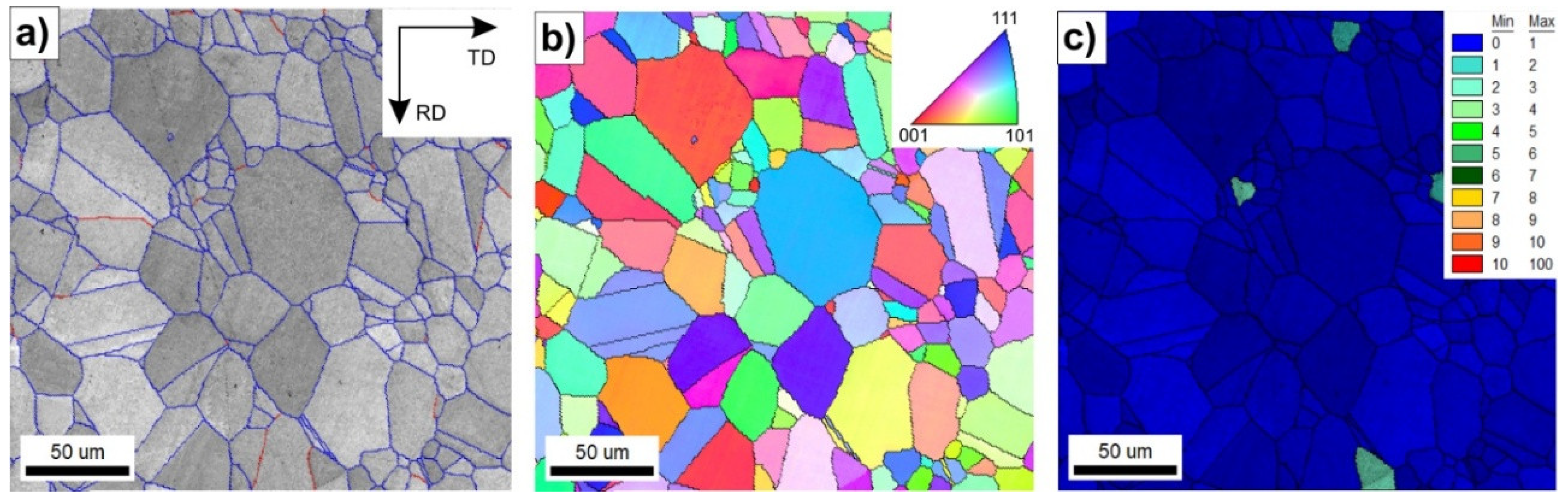
Figure 2.
The grain orientation spread (GOS) maps (a,c,e) and IPF maps of with high angle boundaries (≥15°) marked by black lines (b,d,f) of Ni3Al-based strips after hot rolling up to 0.3 strain at a strain rate
Figure 2.
The grain orientation spread (GOS) maps (a,c,e) and IPF maps of with high angle boundaries (≥15°) marked by black lines (b,d,f) of Ni3Al-based strips after hot rolling up to 0.3 strain at a strain rate
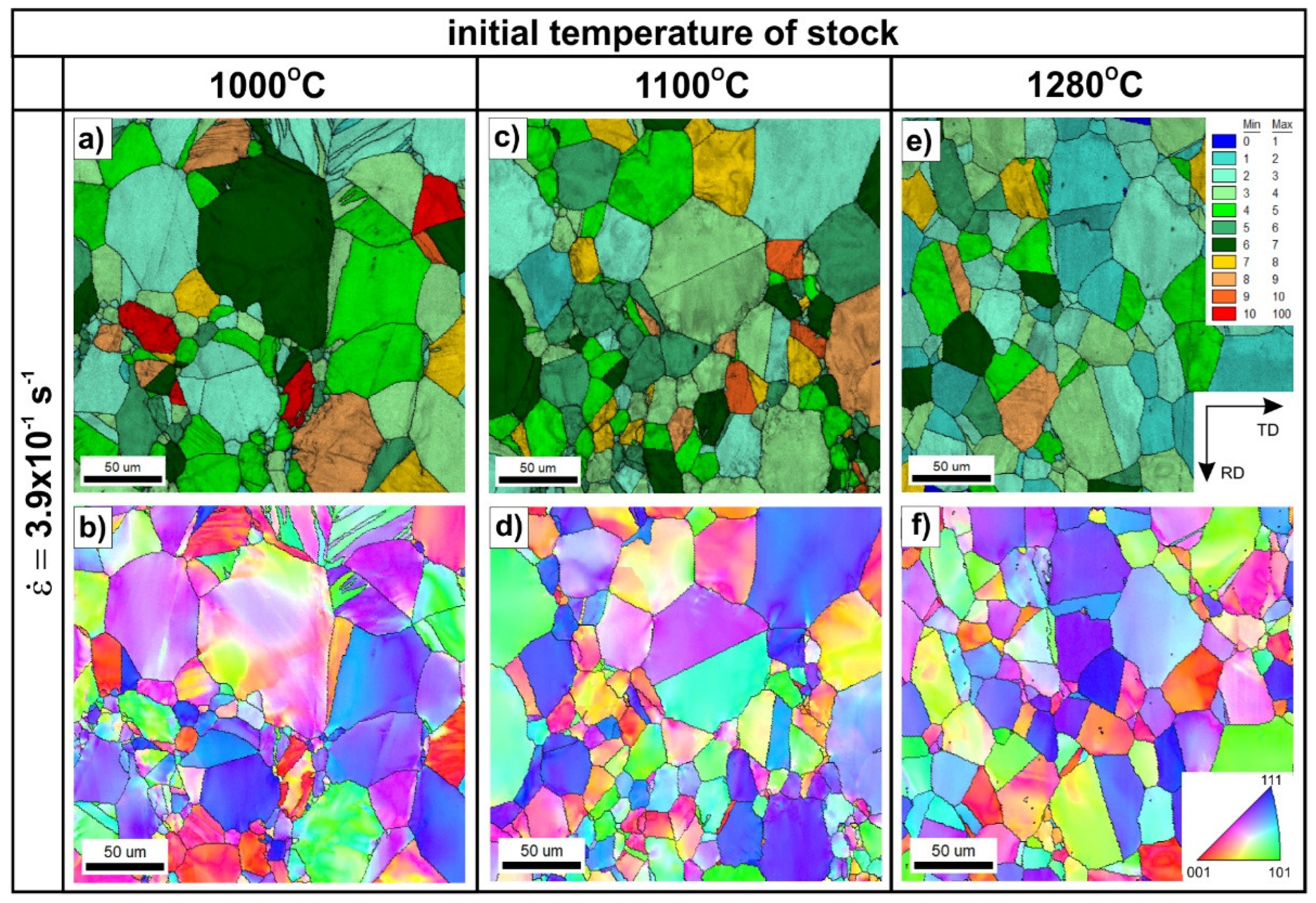
Figure 3.
The grain orientation spread (GOS) maps (a,c,e) and the IPF maps with high angle boundaries (≥15°) marked by black lines (b,d,f) of Ni3Al-based strips after hot rolling up to 0.3 strain at: strain rate of
Figure 3.
The grain orientation spread (GOS) maps (a,c,e) and the IPF maps with high angle boundaries (≥15°) marked by black lines (b,d,f) of Ni3Al-based strips after hot rolling up to 0.3 strain at: strain rate of
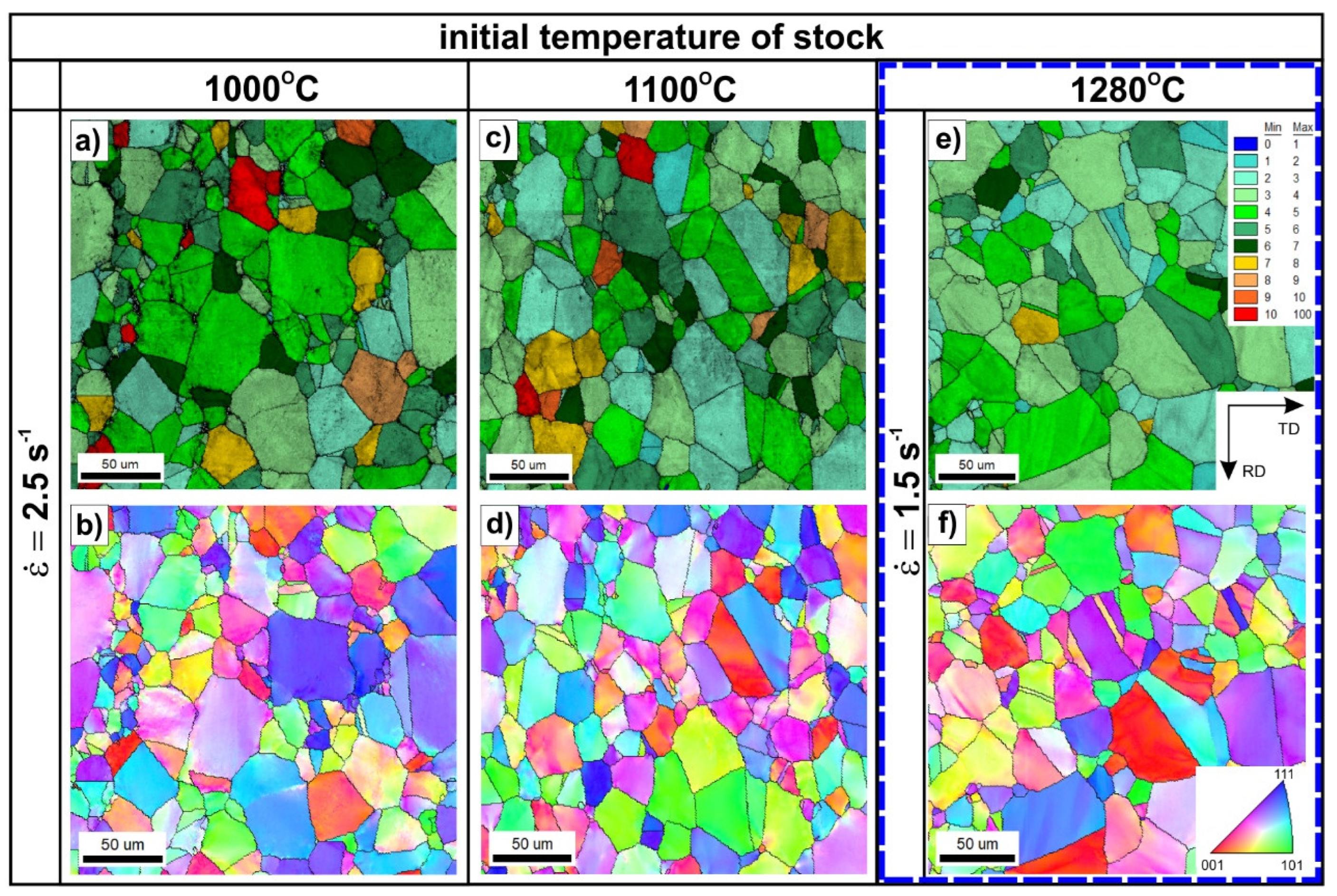
Figure 4.
The results of quantitative EBSD analyses obtained for the investigated material: (a) average GOS values, (b) relative IQ values.
Figure 4.
The results of quantitative EBSD analyses obtained for the investigated material: (a) average GOS values, (b) relative IQ values.
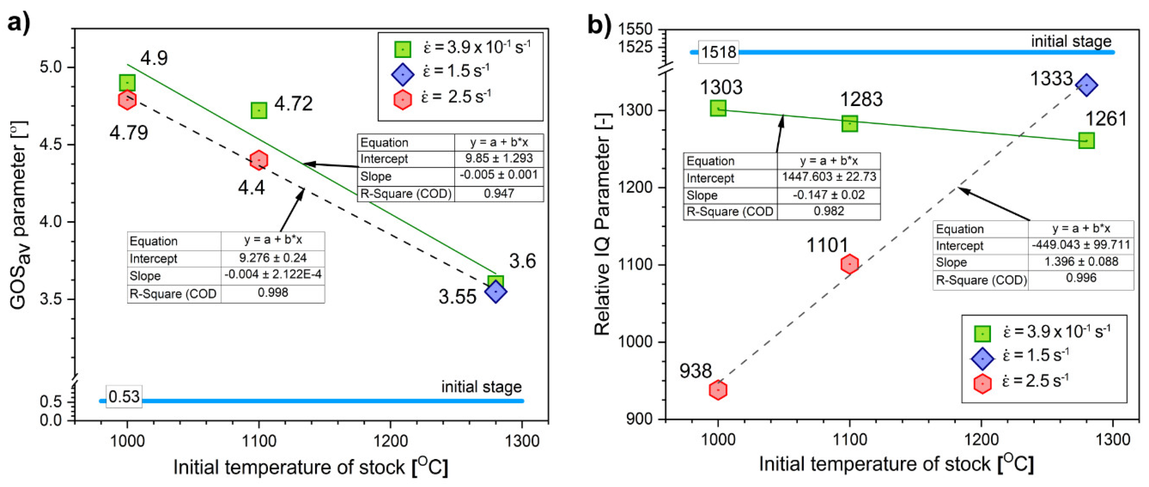
Figure 5.
The EBSD IPF maps with high angle boundaries marked by black lines of Ni3Al-based intermetallic alloy after the hot-rolling at T=1000 °C at
Figure 5.
The EBSD IPF maps with high angle boundaries marked by black lines of Ni3Al-based intermetallic alloy after the hot-rolling at T=1000 °C at
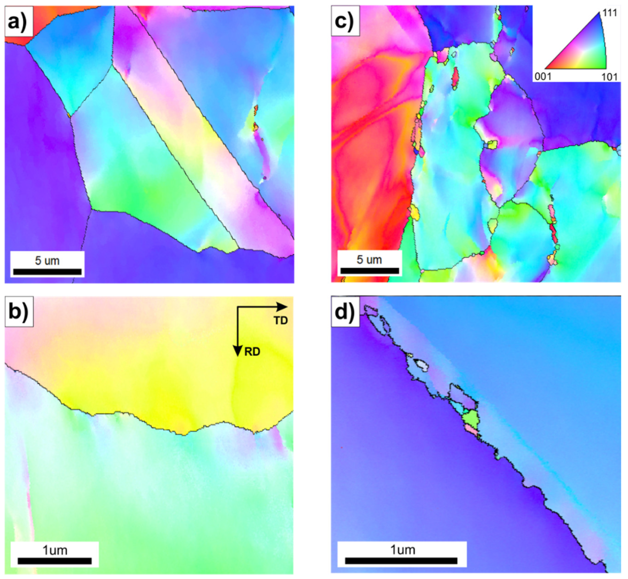
Figure 6.
The EBSD IPF maps with high angle boundaries marked by black lines of Ni3Al-based intermetallic alloy after the hot-rolling T=1100 °C and
Figure 6.
The EBSD IPF maps with high angle boundaries marked by black lines of Ni3Al-based intermetallic alloy after the hot-rolling T=1100 °C and
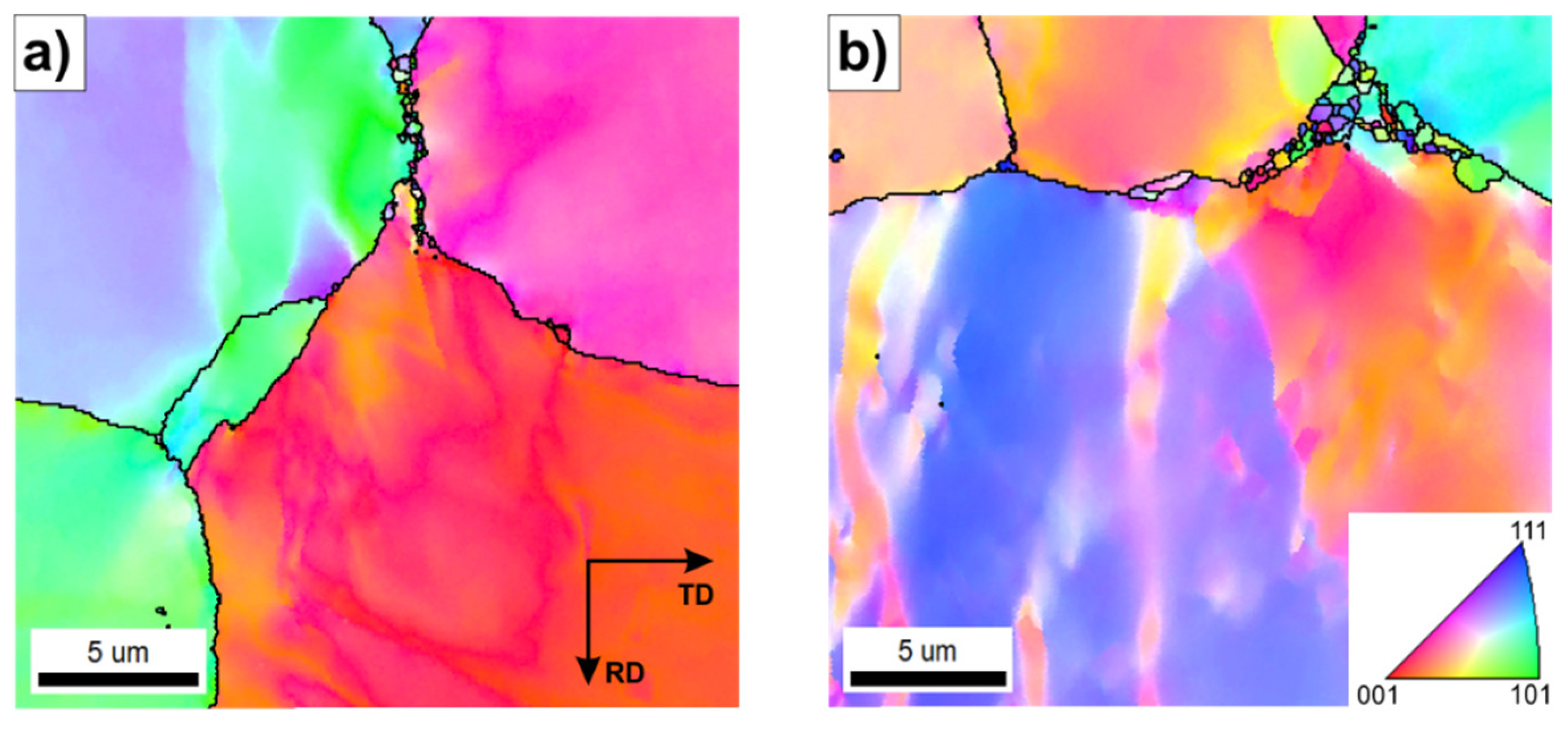
Figure 7.
The EBSD IPF maps (high angle boundaries marked by the black lines) of Ni3Al-based alloy after the hot-rolling at T= 1280 °C and at
Figure 7.
The EBSD IPF maps (high angle boundaries marked by the black lines) of Ni3Al-based alloy after the hot-rolling at T= 1280 °C and at
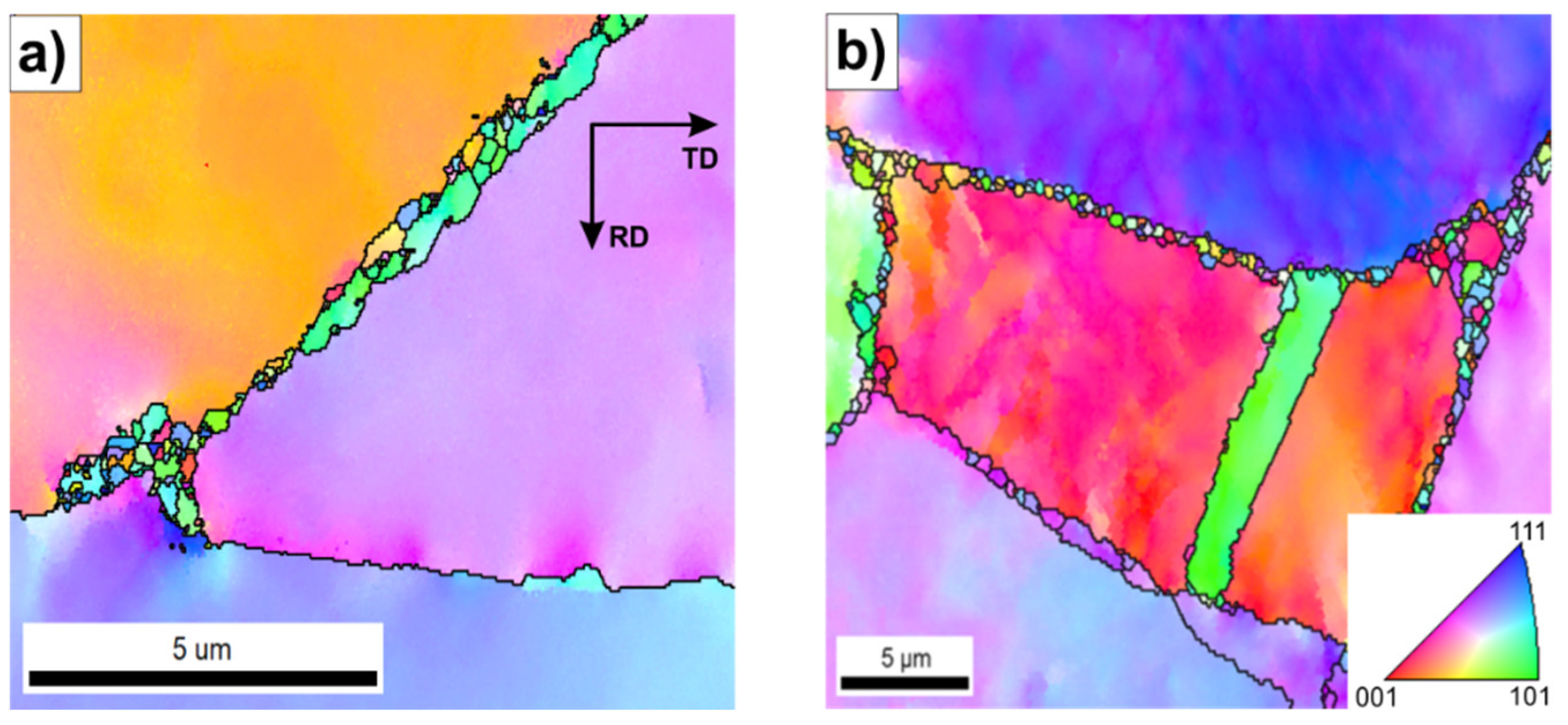
Figure 8.
Influence of strain rate
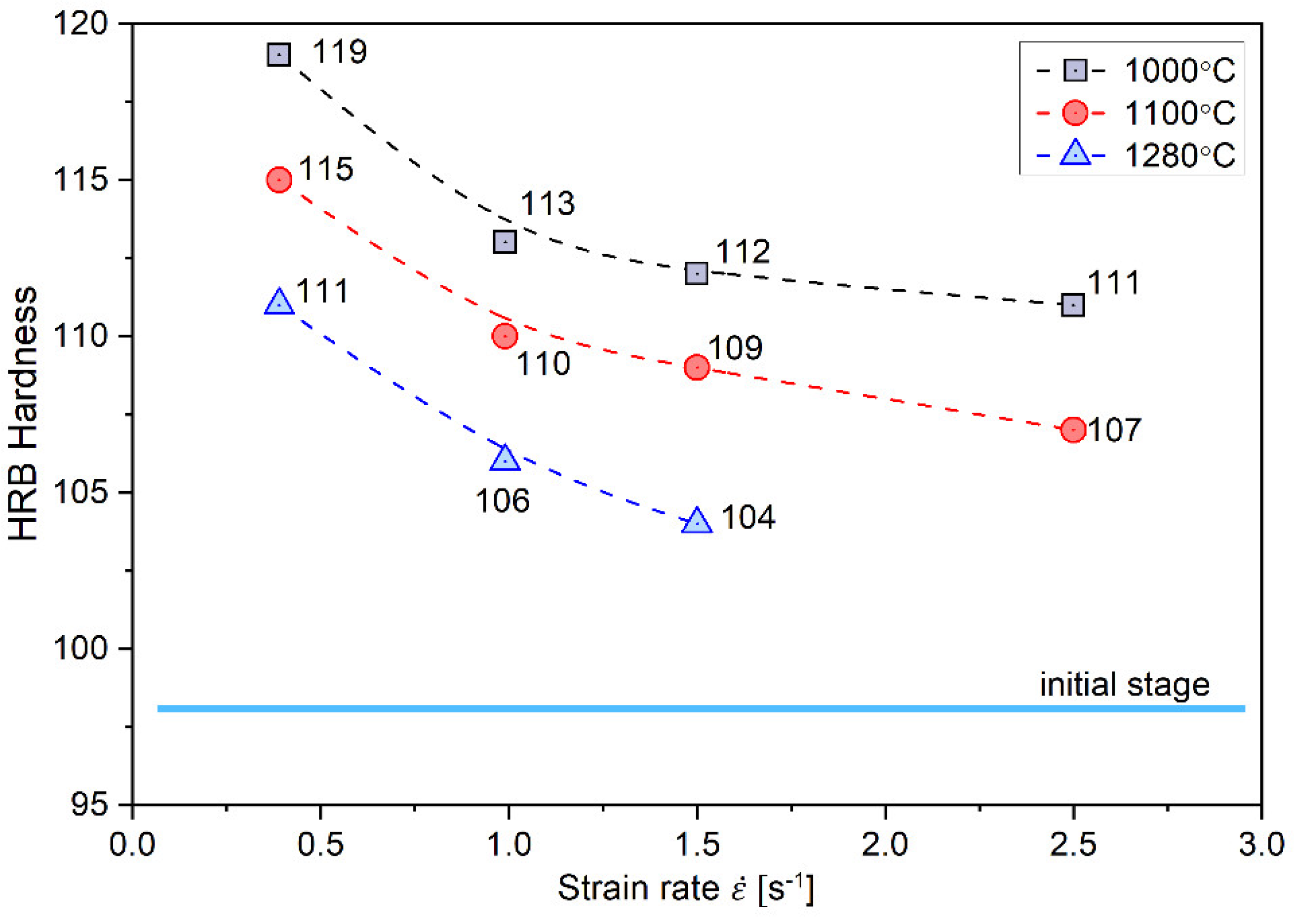
Figure 9.
Schematic diagram of the numerical model of heat conduction in a rolled plate (description in the text).
Figure 9.
Schematic diagram of the numerical model of heat conduction in a rolled plate (description in the text).
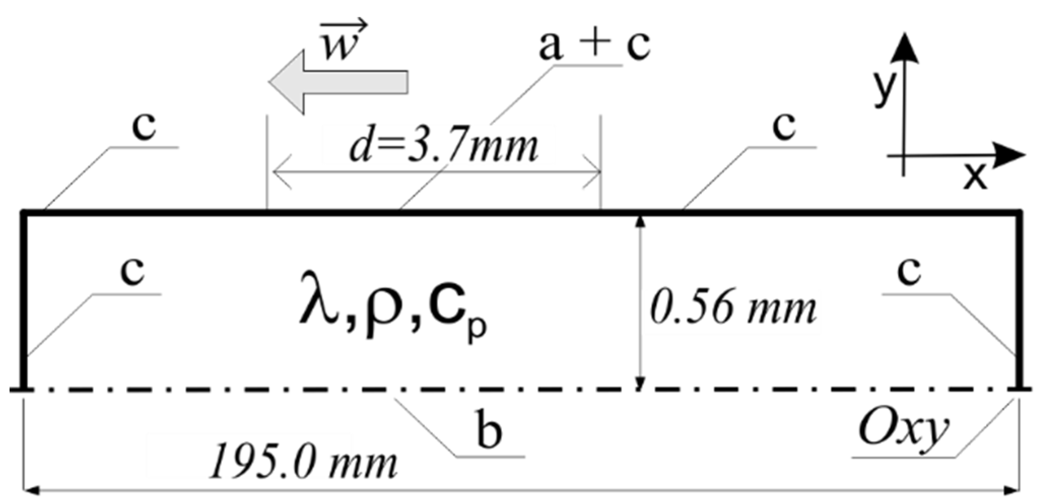
Figure 10.
The course of temperature changes obtained from the numerical model in individual points of the rolled strip during hot rolling (A, C, E- core, B, D, F – surface).
Figure 10.
The course of temperature changes obtained from the numerical model in individual points of the rolled strip during hot rolling (A, C, E- core, B, D, F – surface).
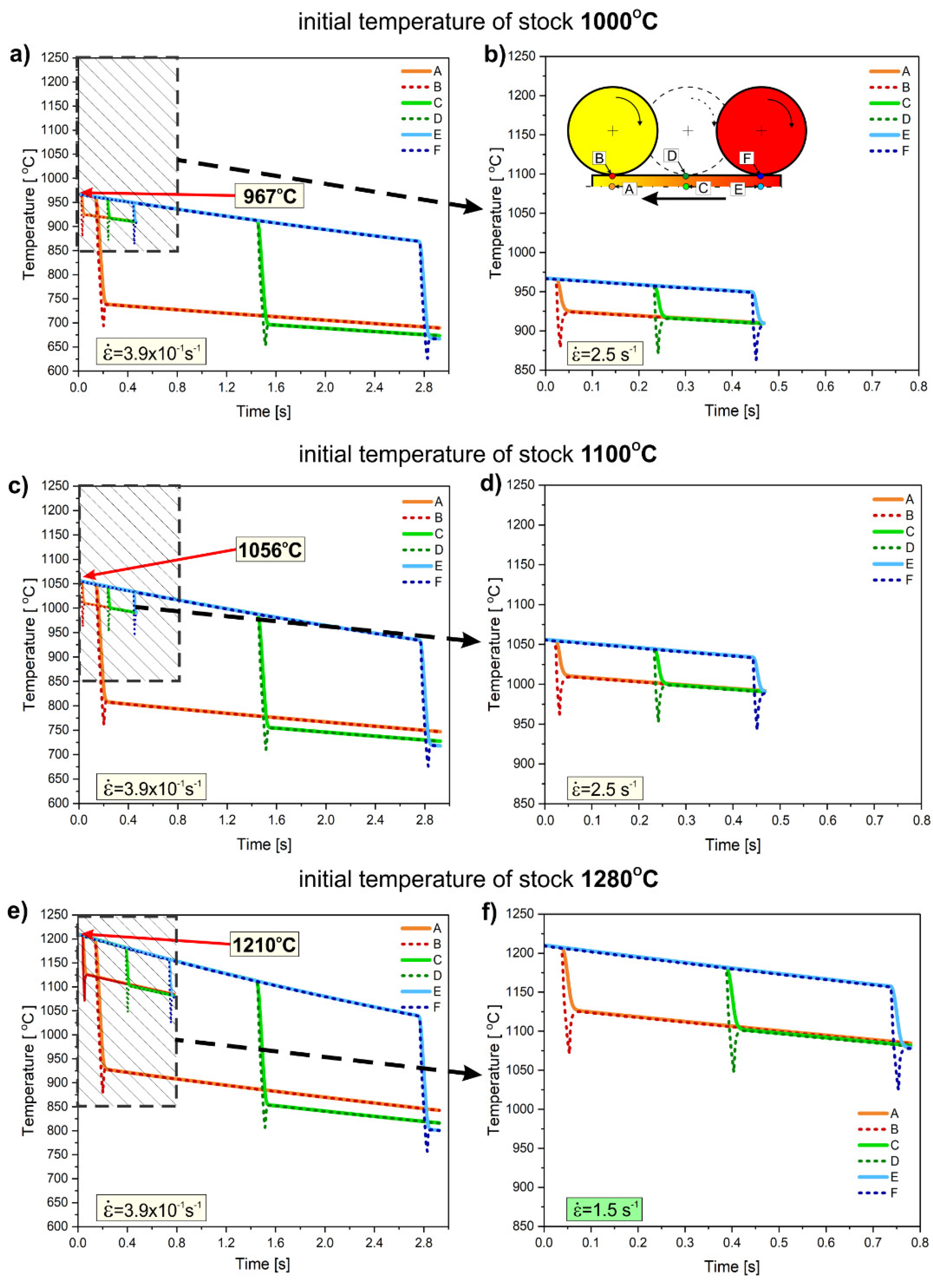
Figure 11.
Effect of numerical modelling-determined temperature in the core of Ni3Al strips centre (Figure 10, point C) during rolling on HRB hardness, taking into account from rolling process parameters (average values).
Figure 11.
Effect of numerical modelling-determined temperature in the core of Ni3Al strips centre (Figure 10, point C) during rolling on HRB hardness, taking into account from rolling process parameters (average values).
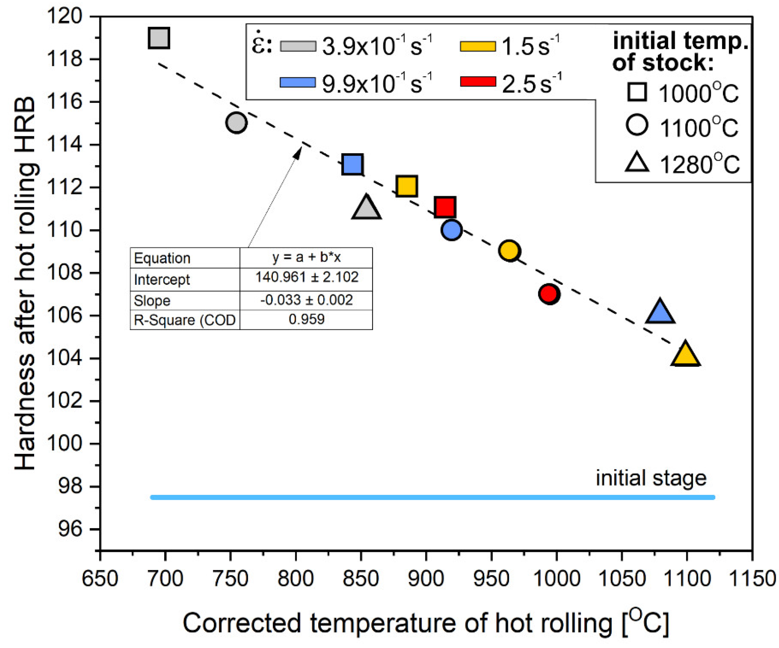

Table 1.
Material properties adopted for calculations based on extrapolation of the results of measurements by Panas [40] and Terpilowski [41] for the Ni-22.1Al-0.26Zr-0.1B (at.%) alloy.
| Temperature | Specific heat | Relative elongations | Density |
Thermal diffusivity |
Thermal conductivity |
|
t [°C] |
cp [J·kg−1·K−1] |
ε [mm·m−1] |
ρ [kg·m−3] |
a [mm2·s−1] |
λ [W·m−1·K−1] |
| 0 | 466 | -0.31 | 7592 | 4.27 | 15.1 |
| 100 | 482 | 0.91 | 7564 | 4.75 | 17.3 |
| 200 | 499 | 2.21 | 7535 | 5.24 | 19.7 |
| 300 | 515 | 3.58 | 7504 | 5.73 | 22.1 |
| 400 | 532 | 5.02 | 7472 | 6.21 | 24.7 |
| 500 | 548 | 6.54 | 7438 | 6.70 | 27.3 |
| 600 | 564 | 8.13 | 7403 | 7.18 | 30.0 |
| 700 | 581 | 9.80 | 7366 | 7.67 | 32.8 |
| 800 | 597 | 11.54 | 7328 | 8.16 | 35.7 |
| 900 | 614 | 13.35 | 7289 | 8.64 | 38.7 |
| 1000 | 630 | 15.23 | 7249 | 9.13 | 41.7 |
| 1100 | 647 | 17.19 | 7207 | 9.61 | 44.8 |
| 1200 | 663 | 19.22 | 7164 | 10.10 | 48.0 |
| 1300 | 680 | 21.33 | 7120 | 10.59 | 51.2 |
Table 2.
The values of parameters characterizing the initial and boundary conditions adopted for the calculations.
Table 2.
The values of parameters characterizing the initial and boundary conditions adopted for the calculations.
| Temperature |
Heat transfer coefficient |
Thermal contact surface resistance |
Surface emissivity | |
|
t [°C] |
T [K] |
α [W·m−2·K−1] |
rcont [m2·K·W−1] |
ε [-] |
| 20 | 293 | 10 | 7.69·10−5 | 0.7 |
Disclaimer/Publisher’s Note: The statements, opinions and data contained in all publications are solely those of the individual author(s) and contributor(s) and not of MDPI and/or the editor(s). MDPI and/or the editor(s) disclaim responsibility for any injury to people or property resulting from any ideas, methods, instructions or products referred to in the content. |
© 2025 by the authors. Licensee MDPI, Basel, Switzerland. This article is an open access article distributed under the terms and conditions of the Creative Commons Attribution (CC BY) license (http://creativecommons.org/licenses/by/4.0/).
Copyright: This open access article is published under a Creative Commons CC BY 4.0 license, which permit the free download, distribution, and reuse, provided that the author and preprint are cited in any reuse.


