

Submitted:
21 May 2025
Posted:
22 May 2025
You are already at the latest version
Abstract
An efficient and affordable low carbon binder, based on Yaoundé local excavation earth, that achieves sufficient mechanical strength and water resistance for rendering applications has been formulated. Blends of Portland cement (PC) and laterite calcined at 750∘C (CL) with varying weight ratios were investigated. The pozzolanic reaction was detected when replacing up to 70% PC by CL. The research investigated laterite sand mortar formulations, with varying proportion of fine particles. The strength of mortar pastes containing 40% and 100% PC in the binder reached the same level. The compressive strength increased with decreasing proportion of fine particles, and reached the maximum value of 10.2 MPa when the laterite sand grain size is larger than 100μm. The water absorption tests by capillarity showed that the formulation belongs to class Wc2 mortar, for all the laterite sand granulometries. The water absorption by capillarity coefficient decreased with increasing fines proportion : the highest value of 0.051kg/(m2.min0.5) was obtained when the laterite sand contains no fine particles. Furthermore, the study explored the reuse potential of the grinded mortar : the fines showed pozzolanic properties and can be used as supplementary cementitious material, and the largest particles are suitable for lime stabilization.
Keywords:
low carbon binder
; calcined laterite
; pouzzolanic reaction
; laterite sand mortar
; water resistance
; mechanical strength
; circular economy
1. Introduction
The widespread use of portland cement in concrete [1] combined with the depletion of non renewable mineral ressources like sand or gravels, whose mining impacts on human health and natural ecosystems [2], presents significant challenges and motivates the development of alternative building systems based on circular economy.
In Yaoundé, Cameroon, where the increasing population growth rate reached in 2020 [3], rapid urbanization has led to the development and saturation of precarious neighborhoods, mainly composed of poto poto shelters vulnerable to the hydric stress related to the tropical situation of the city [4]. Moreover, sand and gravel extraction in Cameroon severely impact the environment, particularly through the degradation of mangroves, which are areas of high ecological importance. Indeed, they contribute, among other things, to carbon sequestration. Their alteration leads to harmful consequences: degradation of biodiversity, increased coastal erosion, reduction in fish production and in soil fertility [5]. In this context, it is important to develop low-carbon binders based on circular waste management, in order to protect natural resources and reduce emissions. To meet this objective, a valuable resource is available in Yaoundé: the kaolinite-rich excavated soil, that is available in abundance in 12 quarries with an estimated volume of almost [6], and that already showed great interest in the building sector.
Indeed, Lateritic soil is primarily used for compressed earth blocks (CEB) manufacturing. Different types of stabilization have been investigated in the literature [7]: mechanical stabilization that consists in compacting the soil with optimum water content [8,9], physical stabilization through granulometry control [10] or the addition of fibers that act at the macroscopic level [11,12], and chemical stabilization such as the addition of portland cement [9,10,13], lime [14], fly ash [15] or the use of geopolymer binder [16] for instance. According to the Cameroonian standard NC 102-115 (2007), the minimum compressive strength required for compressed unstabilized laterite blocks is 2 MPa, while the compressive strength should reach 4MPa for compressed stabilized earth bricks [13]. The mechanical resistance reported in the literature for unstabilized laterite blocks fulfil the standard requirement, however, such blocks melt when immersed in water [6,8,9]. This fact has been verified in a preliminary study of the present project: the mechanical resistance of CEB made from lateritic soil extracted at Yaoundé reached 4,77 MPa, but did not resist 24 hours water immersion. With a minimum cement stabilisation of 6%, CEB ally mechanical resistance and water stability [6,8,9]. External stabilisation has been investigated: 6 to 10% CEB was incorporated in the outer part of the bloc with a thickness varying from 0.75 mm to 2.25 mm while the inner part remained unstabilised. According to the study, a stabilisation crown of 2.25 mm thickness with 8% cement enabled to meet the construction standards in terms of mechanical strength and water resistance [8]. In this work, the development of an external stabilisation solution is investigated in the form of a rendering mortar.
Other valorization axis have been proposed in the literature: lateritic sand can be recycled as fine aggregates in cement concrete [17,18] and the fine fraction of kaolinite rich laterite, constisting of grains passing through a 100 sieve, can be activated by thermal treatment and constitutes an efficient precursor for geopolymerization [19,20,21,22,23,24,25,26] or can be used as supplementary cementitious material in cement based concrete [27,28,29,30,31]. In fine river sand mortars, replacing portland cement by calcined laterite enabled to achieve 5.5 MPa strength [28]. However, raw laterite mortars with a similar cement content led to higher compressive strength [32], indicating that raw laterite is an efficient substitute to sand river in mortars.
In this context, this work focuses on the development of a rendering mortar based on a low carbon binder. Among the different valorization approaches that have been described in the literature, the development of cementitious systems has been investigated. This choice is motivated by the pozzolanic activity that laterite fines exhibit after appropriate thermal and mechanical treatments, based on material and physical characterization. In cementitious systems, portlandite is part of the hydration products of portland cement and is able to react with the reactive silicon, aluminum and iron oxides (, and ) of pozzolanic materials in the presence of water, according to the pozzolanic reaction:
where CH stands for calcium hydroxyde , H for water, and CSH, CAH, CASH stand for calcium silicate hydrate, calcium aluminate hydrate and calcium alumino-silicate according to cement notations. The developed binder is a mix of calcined laterite blended with portland cement. The lowest cement ratio, ensuring mechanical performance, is determined. The efficiency of the developed binder is measured by the mechanical resistance and the water resistance of lateritic sand based mortars with varying granulometry. To finish with, promising recycling strategies are presented.
2. Materials and Methods
2.1. Materials
2.1.1. Raw Materials
Laterite was collected in Yaoundé (GPS coordinates 3°43′19.1″ N and 11°32′00.0″ E ), crushed in a ceramic mortar and sieved with BS 100 µm. Two sieving methods were used: dry sieving enabled to achieve rapid partial sieving of raw laterite, whereas wet sieving enabled to fully sieve the raw laterite. The non passing fraction was used as lateritic sand, whereas fines with particle size smaller than 100 µm entered the binder formulation.
Laterite fines were calcined in a Solo 111-23/13/40 electric furnace at temperatures ranging from 500 to 750 °C during four hours. After calcination, the laterite fines cooled in open air and were sieved to BS 100 µm for disagglomeration.
Portland cement was purchased from a Yaoundé local supplier. Grade CEM II B-P 42.5 R was available at an affordable price and was therefore used for the present investigations. To evaluate the pozzolanic activity of the calcined laterite, KFN Nekapur hydrated calcium hydroxide was used.
2.1.2. Pozzolanic Activity of Calcined Laterite
The pozzolanic activity was determined by measuring the mechanical resistance of equal weight mixtures of lime and calcined laterite with calcination temperatures varying between 500 °C and 750 °C, designated as CL-500-CH to CL-750-CH, and water to solid ratio of 0.65. The pastes were cast into sealed cylindrical molds of 20 mm diameter and 40 mm height, stored at room temperature, and demolded after 7 days. The samples were cured at room temperature in plastic bags containing wet compresses. The samples were heated at 50 °C for 24h prior to material characterization. For each formulation, 3 samples have been prepared.
2.1.3. Binder Pastes
Table 1 summarizes the composition of the blends that were cast and analysed throughout this study. The water to solid ratio, referred to as was determined for each set of samples to ensure suitable workability of the mixes. Binder pastes were prepared according EN-196-1 standard. The binder pastes were casted into sealed cylindrical molds of 20 mm diameter and 40 mm height, stored at room temperature, and demolded after 7 days ageing. Afterwards, they were cured at room temperature in plastic bags. The samples were heated at 50 °C for 24h before material characterization. For each formulation, 3 samples have been prepared.
2.1.4. Mortar Pastes
Mortar pastes were prepared with the following weight ratio: one part of binder mixed with three parts of "lateritic sand", which was alternatively:
- excavation laterite containing by mass fine particles, labelled as LAT70/30,
- partially sieved laterite that contained by mass fine particles, labelled as LAT60/40,
- or the totally sieved laterite containing particles with grain sizes larger than , labelled as LAT0/100.
The water content, expressed as water to binder mass ratio, was adjusted to achieve similar workability for all formulations. Table 2 details the weight percent composition of the binder, the laterite sand granulometry and the water content, measured as the ratio between the mass of water (w) and the mass of binder (b).
Mortar pastes were prepared in a planetary mixer according to EN 196-1 standard. The blend was cast into 40 mm x40 mm x160 mm prismatic molds. The samples were covered with a plastic foil during 24h and then demolded. The prisms were sealed in plastic bags until 28 days ageing. 3 hours prior to the mechanical testing the samples were in ambient laboratory conditions. For each formulation, 3 samples have been prepared.
2.1.5. Reuse Potential of End of Life Grinded Mortar
The hardened CEM40- LAT 0/100 mortar after 28 days of cure has been used to consider the possibility of closing the life cycle loop of the developed mortar formulation. To this extent, the mortar has been grinded using a A077-01 micro deval abrasion machine, at a speed of 100 r.p.m. during 30 minutes.
Three formulations have been tested to assess the potential of reuse of mortar fines particles smaller than , with the following mass compositions and water ratio to achieve suitable workability:
- lime and mortar fines, referred to as CH75MF25, with a water to solid ratio of 0.5;
- CEM and limestone filler, referred to as CEM75LF25,with a water to solid ratio of 0.345;
- CEM and mortar fines, referred to as CEM75MF25, with a water to solid ratio of 0.345.
The sample preparation and storage are described in Subsection 2.1.3.
Prismatic samples of grinded mortar with particle sizes smaller than stabilised with hydrated lime have been casted and stored as described in Subsection 2.1.4. The water content, measured as the ratio between the mass of water and the mass of solid was 0.30. The sample preparation and storage are described in Subsection 2.1.4.
2.2. Characterization Methods
Particle size was investigated using Malvern panalytical mastersizer 3000. Ethanol was used as dispersent and refractive index 1.58 was assumed.
In order to qualify the reactivity of the laterite fines, water demand, that is a semi-quantitative test giving an indirect measure of specific surface area of the particles, was performed. 50 g of powder was mixed with water in order to reach the plasticity limit. The ratio of the corresponding amount of water over the mass of powder is referred to as the water demand.
Oxide content was measured with a S2 PUMA Brucker spectrometer.
The diffraction patterns were obtained using the Bruker D2 Phaser diffractometer, with a Cu tube (30kV, 10mA) and a Ni filter. The recordings were made for ranging from 10 ° to 55 ° (increment 0.02s, time per step 0.5s).
Spectrum two Perkin Elmer spectrometer was used to analyse raw laterite.
Thermo-gravimetric analysis was carried out using the Netzsch TG 209 F3 Tarsus thermo-microbalance, under nitrogen atmosphere. The temperature ranged from 20 to 950 °C with a heating rate of 5 °C/min, followed by a 60 min step at 950 °C.
The compression resistance of cylindrical and prismatic samples were assessed using Walter+Baï LFM 400 Press, according to EN ISO 6892-1 standard. A displacement rate of 2mm/min was prescribed for cylindrical samples and a loading rate of 50 N/s was applied to prismatic molds.
Water absorption tests by capillarity were performed according to EN 15801 standard.
3. Results and Discussion
3.1. Raw Material Analysis
3.1.1. Particle Size
Lateritic Sand
Wet sieving of raw laterite enabled to assess the proportion of fines, with particle size smaller than , which amounts to by mass. Figure 1 shows the particle size distribution curve for the particles larger than present in raw excavation laterite.
Lateritic Fines
Granulometry and specific surface area are key parameters driving the pozzolanic activity. The average particle size obtained for crude laterite fines and calcined laterite fines at 750° were 10.4 and 20.6 respectively. The average particle size is smaller for crude laterite than for calcined laterite. This is related to an agglomeration effect reported elsewhere [25,26]. One can note that the values obtained for crude and calcined laterite fines are higher than the value of metakaolin that is 4.35 [33].
Water demand, which is an indirect measure of the specific surface area, is 0.52 for crude laterite fines and 0.63 for calcined laterite fines. The higher water demand obtained for calcined laterite attests that the calcination increased the reactivity. Due to the high value of water demand of calcined laterite, the water to solid ratio will be carefully determined for each formulation in order to achieve a suitable workability.
3.1.2. XRF
XRF analysis of CEM, laterite, and metakaolin are presented on Table 3. Laterite exhibits high contents of , and , the sum of the three oxide contents exceeding . Upon calcination, the presence of these free and reactive oxides are responsible of the pozzolanic activity of laterite and enable to consider low cement ratios in this study.
3.1.3. XRD
Figure 2 shows the XRD pattern of crude laterite and laterite calcined at 500°, 600° and 750°, referred to as CL-500, CL 600 and CL-750. The presence of kaolinite is detected through the diffraction peaks located at 12.5 °,20 °, 21.2 °, 25.3 °, 35 °, 38.4 ° and 45.5° that disappear upon calcination. After calcination, there is also the transformation of goethite to hematite. Goethite reflections are detected at 33.5 ° and 36 ° in crude laterite pattern and hematite is visible at 19.8 °, 33.3 ° and 35.7 ° in calcined laterite patterns. Quartz reflections are visible at 20.8°, 25.2 °, 26.7°, 39.4 °, 42.5° and 50°.
3.1.4. FTIR
The FTIR spectrum of crude and calcined laterite are presented on Figure 3. The presence of kaolinite is detected through a set of well-resolved bands, that disappear or shift upon calcination [31,34,35,36,37,38]:
- OH stretching bands located at 3686, 3651 and 3610 cm−1. These bands disappear upon calcination: this accounts for deshydroxylation of laterite;
- Si-O deformation bands located at 1119, 1028, 1001 and 684 cm−1. Upon calcination these narrow bands are replaced by a broad peak located at 1036 cm−1, 1045 cm−1 and 1051 cm−1 when the calcination temperature is 500°, 600° and 750° respectively. The shift to higher wavelength is a sign for the phase transformation from kaolinite to metakaolin;
- Al-OH band located at 909 cm−1 that disappear upon calcination;
- the strong narrow peak located at 526 cm−1 is related to the Al-O-Si deformation band, this peak translates to 777cm−1, which is related with a change in Al coordination;
- the band located at 460 cm−1 is related to Si-O-Si vibration modes, upon calcination this band transforms into a broad band of medium intensity located at 533 cm−1, 545 cm−1 and 558 cm−1 when the calcination temperature is 500°, 600° and 750°. The shift of Si-O-Si vibration mode to higher wavelength attests for the appearance of an amorphous structure.
3.1.5. DTG
Figure 4 presents the DTG analysis of crude and calcined laterite for calcination temperatures ranging from 500 to 750 °C. The crude laterite curve exhibits three peaks, as already reported elsewhere ([39]):
- the first peak between 25 and 100 °C which corresponds to the loss of adsorbed water;
- the second peak between 225 °C and 325 °C corresponds to the decomposition of organic matter and of goethite to hematite;
- the peak between 400°C and 600 °C corresponds to the dehydroxylation of kaolinite.
The kaolinite deshydroxylation peak appears on the crude laterite curve, whereas it completely desappeared when the calcination temperature is higher than 600 °C.
3.2. Pozzolanic Activity of Calcined Laterite
In the literature, the pozzolanic activity of calcined laterite has been assessed [40,41]. In order to define an accurate range for the cement substitution by calcined laterite, pozzolanic activity of CL was assessed according to the procedure described on subSection 2.1.2.
The mechanical strength reported on Figure 5 reveals the occurring of the pozzolanic reaction. As shown in the material characterization tests, calcination induces the transformation of phyllosilicate groups into reactive oxides capable of reacting with in the presence of water to form the possible hydration products: CSH, CASH, CAH. In the literature lower values of compressive strength have been reported for metakaolin-lime blends, ranging from 8 to 12 MPa, for water to solid ratio of 1 [42,43]. This may be related to several causes discussed in the literature : the presence of iron oxydes improves the pozzolanic activity of calcined kaolin [44], the unreacted quartz and iron hydrates present in the laterite fines act as microaggregates and improve the strength [10],the occurence of early age carbonation process that hinders the pozzolanic reaction [33,45].
3.3. Eco-Binder Design
As decribed in Table 1, the first set of blends is caracterized by water to solid ratio of 0.57 for calcined laterite blended cement pastes with cement ratios ranging from to and 0.45 for the blend containing cement. These values ensure a suitable workability for all blends.
Figure 6 shows the compressive strength of calcined blended laterite with cement ratios ranging from to . Pozzolanic activity is revealed for blends containing and of cement: indeed an increase of in compressive strength is recorded between the seventh and twenty-eighth day of curing. Figure 6 shows that the compressive strength linearly increases with increasing cement content up to . The blends containing CEM on one hand and cement and calcined laterite on the other hand exhibit a similar compressive strength for equivalent workability.
Figure 7 shows the XRD curves of the pastes containing , and cement. As expected, excess portlandite was detected in the cement paste containing only CEM, through the reflection peaks located at 18°, 34° and 47.2°. In the blends containing calcined laterite these peaks were not visible, meaning that no portlandite is detected: it was consumed through the pozzolanic reaction. The reaction of the excess portlandite and calcined laterite, as from replacement of cement by calcined laterite has been reported elsewhere [28,30]. In the binder composed of 100% cement, the presence of unreacted di- and tri-calcium silicates is visible in a set of low intensity peaks located around 29°, 32.1° [46,47].
3.4. Mortar Pastes
3.4.1. Mechanical Resistance
Figure 8 shows the compressive strength measured at 1 day and 28 days respectively of the CEM100-LAT60/40 and CEM40-LAT60/40 mortar formulations described on Table 2, obtained with partially sieved laterite as lateritic sand. Water ratio was the same for the two formulations. The same mechanical resistance was obtained for the two mortar blends.
Figure 9 shows the compressive strength of mortar blends formulations with 40% cement and 60% laterite binder, and with varying granulometry of lateritic sand, from raw laterite to completely sieved laterite with grain sizes larger than as described on Table 2. Water ratio was adapted for each blend in order to obtain the same workability: as the proportion of uncalcined fines increases, the water demand increases. Using raw laterite as source of coarse grains enables to achieve sufficient resistance for the formulation of a rendering morter. However, using totally sieved laterite leads to the reduction of water ratio and in turn the improvement of mechanical properties.
3.4.2. Water Absorption by Capillarity Test
Table 4 shows the water absorption tests by capillarity performed on the mortar pastes descibed in Table 2 after 28 days of cure. It is shown that when the binder is composed of CEM, the water absorption by capillarity coefficient is the lowest. When the binder is composed of CEM and calcined laterite, water absorption resistance is better when the lateritic sand granulometry contains the larger quantity of fine particles. This is in line with the ability of fine particles to avoid the formation of pores, thus improving the water absorption resistance.
For all the mortars formulations, the water absorption by capillarity coefficient, measured as the slope of the water absorption by capillarity curves at origin, are smaller than , which classify all the formulation as class W2 mortar according to EN998-1 standard, and ensures they are suitable for rendering applications.
3.5. Closing the Loop for the Developed Solution
The potential of reuse of the developed mortar is assessed here, according to the strategy described in Section 2.1.5. Grinded mortar contains of fine particles with size smaller than .
3.5.1. Pozzolanicity of Mortar Fines
Figure 10 show the compressive strength after 7 and 28 days of curing for the following blends: CEM75LF25, CEM75MF25 with water ratio of 0.345 and CH75MF25 with water ratio of 0.5. It is interesting to see that mortar fines have a more pronounced improvement effect on compressive strength of cement paste than limestone filler. Pozzolanic effect of mortar fines are also evidenced by the evolution of the blends CH25MF25 and CEM75MF25 mechanical properties: the compressive strength increase between 7 and 28 days amounts to 48% and 36% respectively.
Figure 11 shows the X-rays patterns of the following blends: CEM75LF25, CEM75MF25 and CH75MF25. Calcite reflection peaks are visible at 23.5°, 29.4°, 36°, 39.5°, 47.1°, 47.5°, 48.5° in the CEM75LF25 blend curve. In the cement blends, portlandite is visible through the reflection peaks located at 18.1°, 34.2° and 47.1°, however, the peak intensity is relatively smaller in the blend containing mortar fines, suggesting that the pozzolanic reaction occured. In the calcined laterite and lime blend, the presence of kaolinite, present as a residue in the laterite sand, is detected through the 12° reflection peak, and calcium carbonate is visible at 23.5°, 36.6°, 39.5°, while a small quantity of calcium hydroxyde was detected, which accounts for the pozzolanic activity of the mortar fines.
Figure 12 shows the DTG curves of the following blends: CEM75LF25, CEM75MF25 and CH75MF25. The decomposition of hydration products occur up to 160° for the cement blends and up to 300 ° for the lime blend. The presence of portlandite/ was observed in all blends through a peak located at around 440°, and calcium carbonates decomposition occured at temperatures between 600° and 850°. The results are aligned with the XRD observations: calcium hydroxide partially reacts with the iron, aluminum and silicium reactive oxydes contained in the mortar fines, and partially undergoes carbonation mechanism. Carbonation occurs to a smaller extent and less quantity of portlandite was visible in the cement/mortar fines blend compared to the cement/limestone filler blend.
3.5.2. Lime Stabilization of Grinded Mortar
Figure 13 shows the compressive strength of grinded mortar stabilised with hydrated lime, with water/solid ratio of 0.30, measured at 7 and 28 days of curing. The strength is partly provided by the pozzolanic reaction of the mortar fines and lime, but also by the granular skeleton of the ground mortar, which is thought to be a good alternative to river sand.
3.5.3. Life Cycle of the Developed Solution
Figure 14 show the expected life cycle diagram of the developed solution. Environmental impact has been decreased by minimizing the CEM ratio in the binder. It has been shown that the grinded mortar fines show pozzolanic activity, and their incorporation in a cement formulation leads to improved compression resistance compared to the addition of limestone filler. Moreover, it has been shown that the larger part of the grinded mortar, with particle sizes larger than can be incorporated in a lime based rendering mortar, leading to improved compression performance. These concluding remarks open the path for further promising valorization potential of:
- the fines, with particle sizes smaller than , as partial replacement for the calcined laterite, leading to further energy savings;
- the larger aggregates, with sizes larger than as partial replacement for the lateritic sand.
4. Conclusions
The present work demonstrates the feasability of reusing Yaoundé excavation earth to formulate a sustainable low cost rendering mortar, that does not require any specific equipment. A low carbon binder was formulated, based on the pozzolanic activity of calcined laterite, that is composed of reactive oxides capable of consuming the excess portlandite that is an hydration product of portland cement. It was highlighted that:
- replacing of cement by calcined laterite enables to achieve acceptable mechanical strength for cement pastes;
- replacing of cement by calcined laterite enables to achieve the same compression strength than a 100% cement paste for similar workability.
Lateritic sand mortars with a binder formulation containing 40% cement have been assessed, and lead to promising perspective regarding the mechanical strength and water resistance. Indeed, for similar workability, the compressive strength level is equivalent as if the binder was composed of cement only. Regardless of the fines content in the laterite sand, the mortars were all classified as W2 according to water absorption tests by capillarity. However, the higher the fines content, the lower the absorption by capillarity coefficient. To close the life cycle loop of mortar formulation developed in this study, the potential of reuse of the grinded mortar as been assessed:
- mortar fines are pozzolanic and can enter the binder formulation developed here as partial replacement of the calcined laterite, leading to further energy savings;
- the larger particles have the ability to substitute laterite sand in the developed rendering mortar, or equivalent mortars.
Author Contributions
investigation: L.M.L and B. K. D.; data curation: L.M.L and B. K. D., formal analysis: L.M.L, B. K. D. and J. A; resources: B. K. D.; writing - original draft: L. M. L.; writing-review and editing: K. D. B., J. A. and A. B.; Methodology: J.A; supervision: J. A and A. B.; funding acquisition: A. B.
Funding
This research was funded by HES-SO (Western Switzerland University of Applied Sciences).
Data Availability Statement
The original contributions presented in the study are included in the article, further inquiries can be directed to the corresponding author.
Acknowledgments
The author acknowledge the financial support of HES-SO (Western Switzerland University of Applied Sciences).
Conflicts of Interest
The authors declare no conflicts of interest.
Abbreviations
The following abbreviations are used in this manuscript:
| PC | Portland cement |
| CL | calcined laterite |
| CH | Hydrated calcium hydroxyde |
| LATx/100-x | laterite sand containing of fines (<100) |
References
- Serdar, M.; Bjegovic, D.; Stirmer, N.; Pecur, I. B. Alternative binders for concrete: opportunities and challenges. Gradevinar 2019, 71, 200–218. [Google Scholar]
- Bendixen, M.; Iversen, L. L.; Best, J.; Franks, D. M.; Hackney, C. R.; Latrubesse, E. M.; Tusting, L. S. Sand, gravel, and UN Sustainable Development Goals: Conflicts, synergies, and pathways forward. One Earth 2021, 4, 1095–1111. [Google Scholar] [CrossRef]
- Mougoue, B.; Laurentine, N. E. Croissance de la ville de Yaoundé et résiliences aux pandémies. Espace Géographique et Société Marocaine 2021, 43-44, 339–353. [Google Scholar]
- Djatcheu, M.L. Fabriquer la ville avec les moyens du bord: L’habitat précaire à Yaoundé (Cameroun). Géoconfluences 2018. [Google Scholar]
- Moutila, B.L. Pression et dynamique de l’espace côtier à mangrove de Youpwê (Douala). Proceedings of XVIe Colloque International du SIFEE, Yaoundé, september 12-15, 2011.
- Tchamba, A. B.; Nzeukou, A. N.; Tené, R. F.; Melo, U. C. Building potentials of stabilized earth blocks in Yaounde and Douala (Cameroon). Int. J. Civ. Eng. Res. 2012, 3, 1–14. [Google Scholar]
- Lemougna, P.N.; Melo, U.F.C.; Kamseu, E.; Tchamba, A.B. Laterite Based Stabilized Products for Sustainable Building Applications in Tropical Countries: Review and Prospects for the Case of Cameroon. Sustainability 2011, 3, 293–305. [Google Scholar] [CrossRef]
- Eko, R. M.; Mpele, M.; Doumtsop, M. D.; Minsili, L. S.; Wouatong, A. S. Some hydraulic, mechanical, and physical characteristics of three types of compressed earth blocks. Agric. Eng. Int.: CIGR Journal 2006, 8, BC 06 007. [Google Scholar]
- Darman, J. T.; Tchouata, J. H. K.; Ngôn, G. F. N.; Ngapgue, F.; Ngakoupain, B. L.; Langollo, Y. T. Evaluation of lateritic soils of Mbé for use as compressed earth bricks (CEB). Heliyon 2022, 8, e10147. [Google Scholar] [CrossRef] [PubMed]
- Van Essa, L. K.; Kaze, R. C.; Nemaleu, J. G. D.; Tchakoute, H. K.; Meukam, P.; Kamseu, E.; Leonelli, C. Engineering properties, phase evolution and microstructure of the iron-rich aluminosilicates-cement based composites: Cleaner production of energy efficient and sustainable materials. Clean. Mater. 2021, 1, 100017. [Google Scholar] [CrossRef]
- Onugba, M. A.; Eze, C. O.; Atonu, Y. A.; Alih, U. Influence of Fly Ash and Palm Fibre on the Mechanical Properties of Compressed Stabilized Earth Blocks. Asian J. Curr. Res. 2024, 9(4), 7–16. [Google Scholar] [CrossRef]
- Vodounon, N. A.; Kanali, C.; Mwero, J. Compressive and flexural strengths of cement stabilized earth bricks reinforced with treated and untreated pineapple leaves fibres. Open J. Compos. Mater. 2018, 8(4), 145–160. [Google Scholar] [CrossRef]
- Yannick, T. L.; Ali, T. O.; Taypondou, D. J.; Kom, M. I. L. F.; Luc, A. L.; Ngueyep, L. L. M.; Mache, J. R. Statistical analysis of Nkoulou soils properties and suitability for earthen constructions. Heliyon 2022, 8(10), e11141. [Google Scholar] [CrossRef] [PubMed]
- Adeleke, B. K.; Oladipo, A. A.; Alfa, N. M.; Atere, O. A. Comparative Study of Cement and Lime Stabilized Laterite for Compressed Earth Bricks. Journal of Chemical, Mechanical and Engineering Practices 2025, 5, 9–16. [Google Scholar]
- Salleh, N.M.; Roslan, M.H. The stabilization of compressed earth blocs using fly ash. Infrastructure University Kuala Lumpur Research Journal 2015, 3. [Google Scholar]
- Mimboe, A. G.; Abo, M. T.; Djobo, J. N. Y.; Tome, S.; Kaze, R. C.; Deutou, J. G. N. Lateritic soil based-compressed earth bricks stabilized with phosphate binder. J. Build. Eng. 2020, 31, 101465. [Google Scholar] [CrossRef]
- Ukpata, J. O.; Ephraim, M. E.; Akeke, G. A. Compressive strength of concrete using lateritic sand and quarry dust as fine aggregate. ARPN J. Eng. Appl. Sci. 2012, 7(1), 81–92. [Google Scholar]
- Raja, R.; Vijayan, P.; Kumar, S. Durability studies on fly-ash based laterized concrete: A cleaner production perspective to supplement laterite scraps and manufactured sand as fine aggregates. J. Clean. Prod. 2022, 366, 132908. [Google Scholar] [CrossRef]
- Kaze, R. C.; Naghizadeh, A.; Tchadjie, L.; Adesina, A.; Djobo, J. N. Y.; Nemaleu, J. G. D.; Kamseu, E.; Melo, U.C.; Melo, U.C.; Tayeh, B. A. Lateritic soils based geopolymer materials: A review. Constr. Build. Mater. 2022, 344, 128157. [Google Scholar] [CrossRef]
- Kaze, C. R.; Lemougna, P. N.; Alomayri, T.; Assaedi, H.; Adesina, A.; Das, S. K.; Lecomte-Nana, G.; Kamseu, E.; Melo, U.C.; Leonelli, C. Characterization and performance evaluation of laterite based geopolymer binder cured at different temperatures. Constr. Build. Mater. 2021, 270, 121443. [Google Scholar] [CrossRef]
- Kaze, C. R.; Lecomte-Nana, G. L.; Adesina, A.; Nemaleu, J. G. D.; Kamseu, E.; Melo, U. C. Influence of mineralogy and activator type on the rheology behaviour and setting time of laterite based geopolymer paste. Cem. Concr. Compos. 2022, 126, 104345. [Google Scholar] [CrossRef]
- Aziz, A.; Felaous, K.; Alomayri, T.; Jindal, B. B. A state-of-the-art review of the structure and properties of laterite-based sustainable geopolymer cement. Environ. Sci. Pollut. Res. 2023, 30, 54333–54350. [Google Scholar] [CrossRef] [PubMed]
- Metekong, J. V. S.; Kaze, C. R.; Adesina, A.; Nemaleu, J. G. D.; Djobo, J. N. Y.; Lemougna, P. N.; Tatietse, T. T. Influence of thermal activation and silica modulus on the properties of clayey-lateritic based geopolymer binders cured at room temperature. Silicon 2022, 14, 7399–7416. [Google Scholar] [CrossRef]
- Poudeu, R. C.; Ekani, C. J.; Djangang, C. N.; Blanchart, P. Role of Heat-Treated Laterite on the Strengthening of Geopolymer Designed with Laterite as Solid Precursor. Ann. Chim. Sci. Mat. 2019, 43, 359–367. [Google Scholar] [CrossRef]
- Kaze, R. C.; à Moungam, L. B.; Djouka, M. F.; Nana, A.; Kamseu, E.; Melo, U. C.; Leonelli, C. The corrosion of kaolinite by iron minerals and the effects on geopolymerization. Appl. Clay Sci. 2017, 138, 48–62. [Google Scholar] [CrossRef]
- Kaze, C. R.; Lecomte-Nana, G. L.; Adesina, A.; Nemaleu, J. G. D.; Kamseu, E.; Melo, U. C. Influence of mineralogy and activator type on the rheology behaviour and setting time of laterite based geopolymer paste. Cem. Concr. Compos. 2022, 126, 104345. [Google Scholar] [CrossRef]
- Musbau, K. D.; Kolawole, J. T.; Babafemi, A. J.; Olalusi, O. B. Comparative performance of limestone calcined clay and limestone calcined laterite blended cement concrete. Clean. Eng. Technol. 2021, 4, 100264. [Google Scholar] [CrossRef]
- Kaze, R. C., Bikoko. Influence of calcined laterite on the physico-mechanical, durability and microstructure characteristics of portland cement mortar. Innov. Infrastruct. Solut. 2024, 9, 248. [Google Scholar] [CrossRef]
- John, A. T.; Damini, R. G.; Akosubo, I. S. Utilization of Calcined Lateritic Soil as Partial Replacement of Cement on Concrete Strength. Int. J. Sci. Eng. Res. 2019, 10(12), 100–104. [Google Scholar]
- Sabir, B. B.; Wild, S.; Bai, J. Metakaolin and calcined clays as pozzolans for concrete: a review. Cem. Concr. Compos. 2001, 23, 441–454. [Google Scholar] [CrossRef]
- Tironi, A.; Trezza, M. A.; Irassar, E. F.; Scian, A. N. Thermal treatment of kaolin: effect on the pozzolanic activity. Procedia Mater. Sci. 2012, 1, 343–350. [Google Scholar] [CrossRef]
- Aguwa, J. I. Study of compressive strengths of laterite-cement mixes as a building material. Assumption University Journal of Technology 2009, 13(2), 114–20. [Google Scholar]
- Gameiro, A., Silva. Physical and chemical assessment of lime–metakaolin mortars: Influence of binder: aggregate ratio. Cem. Concr. Compos. 2014, 45, 264–271. [Google Scholar] [CrossRef]
- Chavali, Rama Vara Prasad, Reddy, P. Swelling and compressibility characteristics of bentonite and kaolin clay subjected to inorganic acid contamination. Int. J. Geotech. Eng. 2017, 12, 1–7.
- Danner, T.; Norden, G.; Justnes, H. Characterisation of calcined raw clays suitable as supplementary cementitious materials. Appl. Clay Sci. 2018, 162, 391–402. [Google Scholar] [CrossRef]
- Aroke, U. O.; Abdulkarim, A.; Ogubunka, R. O. Fourier-transform infrared characterization of kaolin, granite, bentonite and barite. ATBU journal of environmental technology 2013, 6, 42–53. [Google Scholar]
- Öz, A.; Bayrak, B.; Kavaz, E.; Kaplan, G.; Çelebi, O.; Alcan, H. G.; Aydın, A. C. The radiation shielding and microstructure properties of quartzic and metakaolin based geopolymer concrete. Constr. Build. Mater. 2022, 342, 127923. [Google Scholar] [CrossRef]
- Sengyang, P.; Rangsriwatananon, K.; Chaisena, A. Preparation of zeolite N from metakaolinite by hydrothermal method. J. Ceram. Process. Res. 2015, 16, 111–116. [Google Scholar]
- Kumar, G. S.; Saini, P. K.; Deoliya, R.; Mishra, A. K.; Negi, S. K. Characterization of laterite soil and its use in construction applications: a review. Resour. Conserv. Recycl. 2022, 16, 200120. [Google Scholar]
- Pera, J.; Ambroise, J.; Momtazi, A. S. Investigation of Pozzolanic Binders Containing Calcined Laterites. MRS Online Proceedings Library (OPL). 1991, 245, 25. [Google Scholar]
- Fernandez, R.; Martirena, F.; Scrivener, K. L. The origin of the pozzolanic activity of calcined clay minerals: A comparison between kaolinite, illite and montmorillonite. Cem. Concr. Res. 2011, 41, 113–122. [Google Scholar] [CrossRef]
- Moropoulou, A.; Bakolas, A.; Aggelakopoulou, E. Evaluation of pozzolanic activity of natural and artificial pozzolans by thermal analysis. Thermochim. Acta 2004, 420, 135–140. [Google Scholar] [CrossRef]
- Eires, R.; Nunes, J. P.; Fangueiro, R.; Jalali, S.; Camões, A. New eco-friendly hybrid composite materials for civil construction. Proceedings of ECCM 12 - European Conference on Composite Materials, Biarritz, 2006.
- Ghorbel, H.; Samet, B. Effect of iron on pozzolanic activity of kaolin. Constr. Build. Mater. 2013, 44, 185–191. [Google Scholar] [CrossRef]
- Öztürk, M.; Tanaçan, L.; Barış, K. E. Improving the strength of metakaolin-lime based binder. In MATEC Web of Conferences, Proceedings of SUBLime Conference 2024 – Towards the Next Generation of Sustainable Masonry Systems: Mortars, Renders, Plasters and Other Challenges, Funchal, Madeira, Portugal, November 11-12, 2024; Volume 403, p. 02006.
- Zhao, Q.; Tu, J.; Han, W.; Wang, X.; Chen, Y. Hydration properties of portland cement paste with boron gangue. Adv. mater. sci. eng. 2020, 2020(1), 7194654. [Google Scholar] [CrossRef]
- Maciel, M. H.; Soares, G. S.; Romano, R. C. D. O.; Cincotto, M. A. Monitoring of Portland cement chemical reaction and quantification of the hydrated products by XRD and TG in function of the stoppage hydration technique. J. Therm. Anal. Calorim. 2019, 136(3), 1269–1284. [Google Scholar] [CrossRef]
Figure 1.
Laterite particle size distribution curve
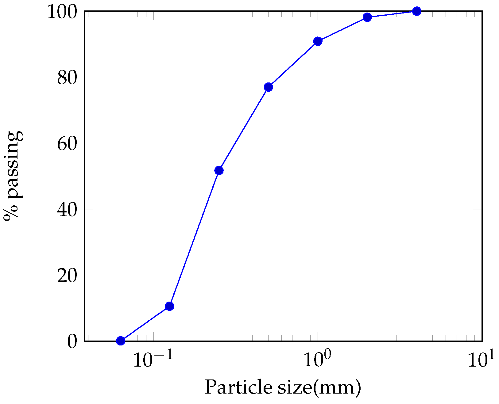
Figure 2.
XRD pattern of crude and calcined laterite for three calcination temperatures: 500, 600 and 750°
Figure 2.
XRD pattern of crude and calcined laterite for three calcination temperatures: 500, 600 and 750°
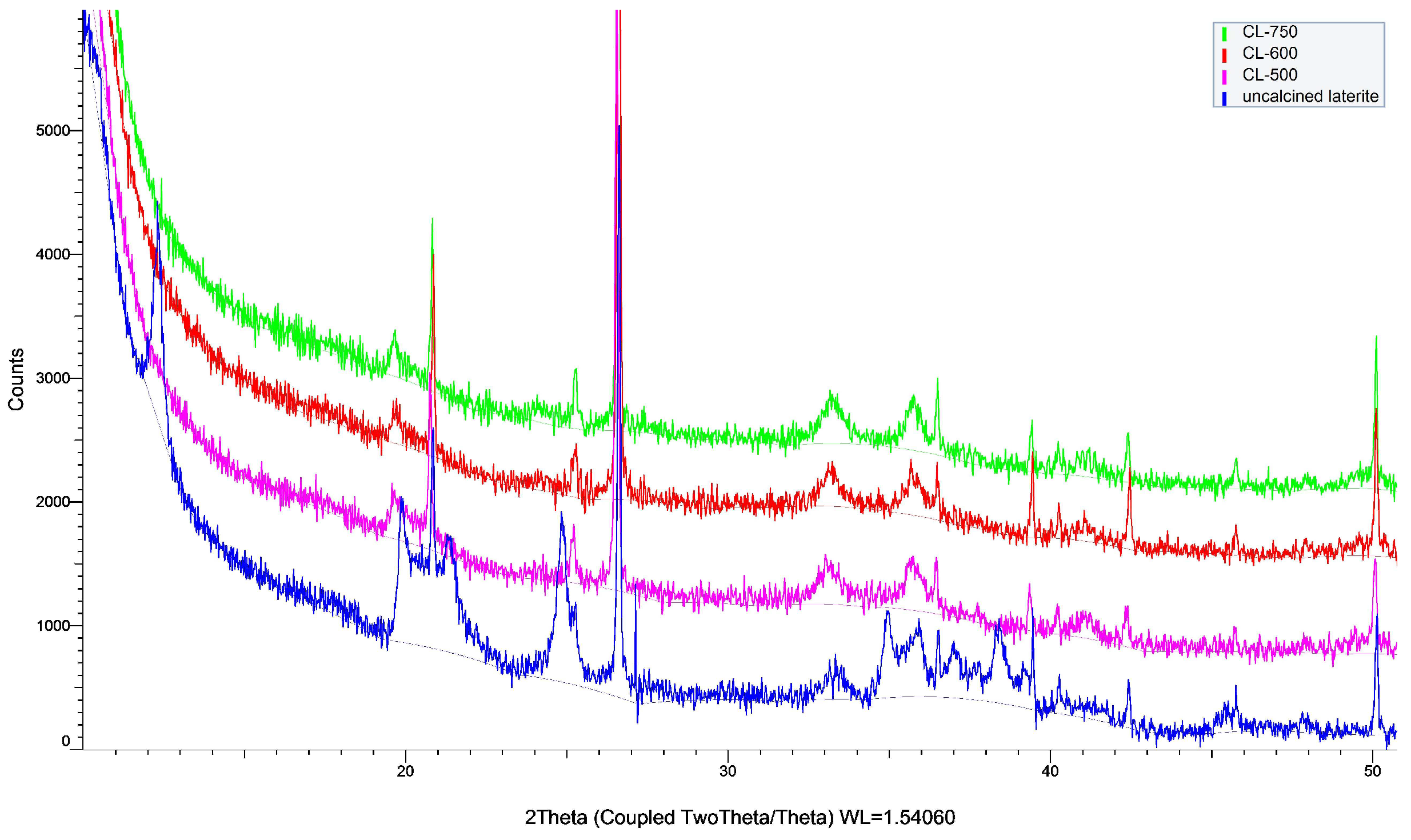
Figure 3.
FTIR spectrum of crude laterite and calcined laterite for three calcination temperatures: 500°, 600° and 750°.
Figure 3.
FTIR spectrum of crude laterite and calcined laterite for three calcination temperatures: 500°, 600° and 750°.
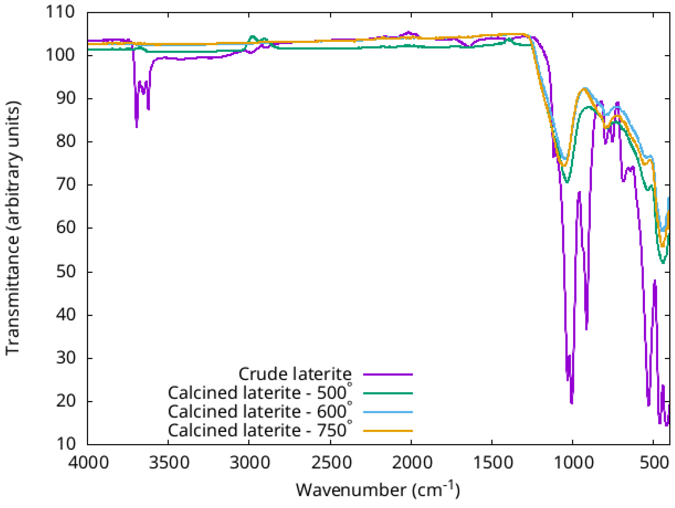
Figure 4.
DTG curves of crude laterite and calcined laterite at 500 °C, 600 °C, 750 °C
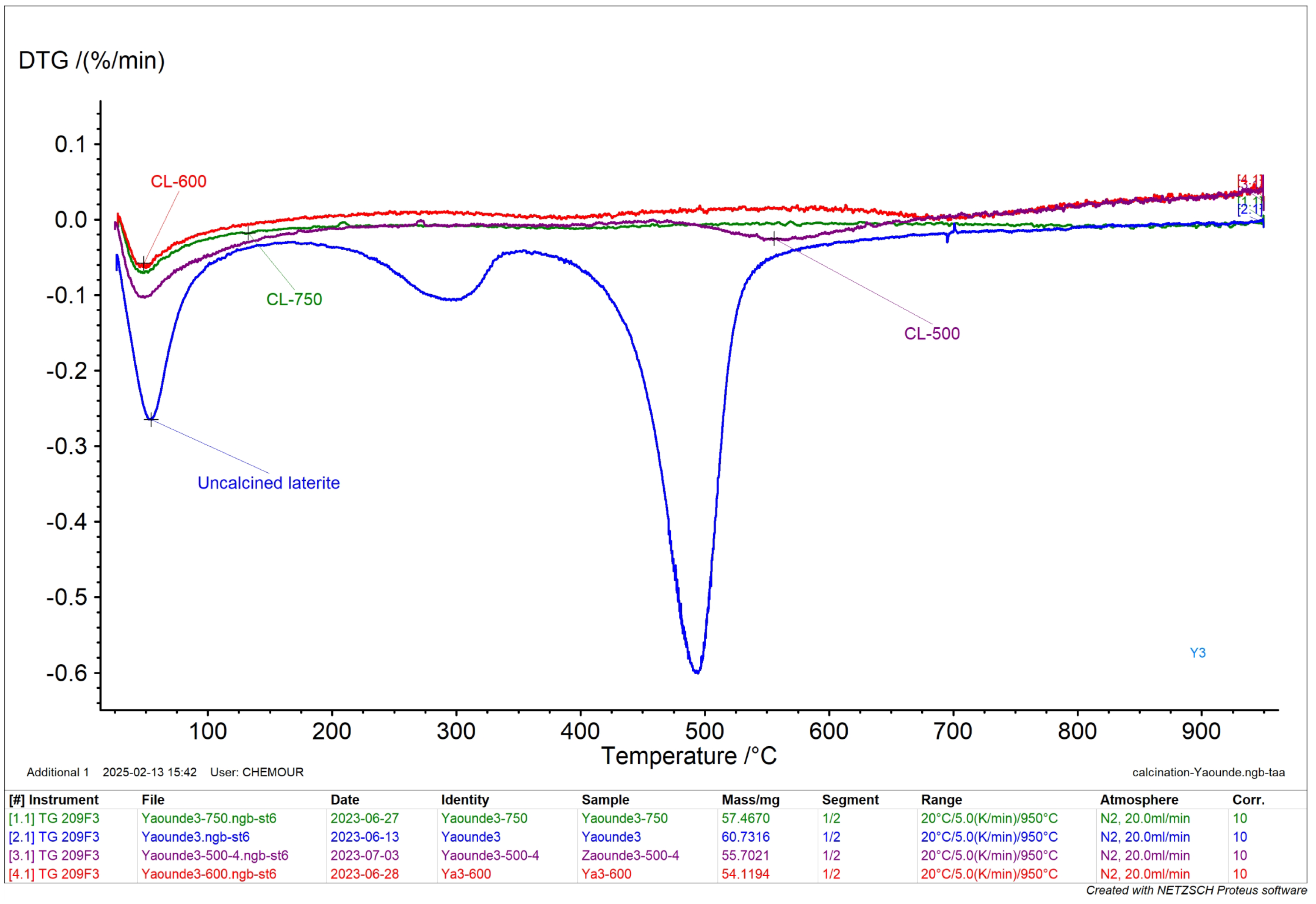
Figure 5.
Reactivity of calcined laterite
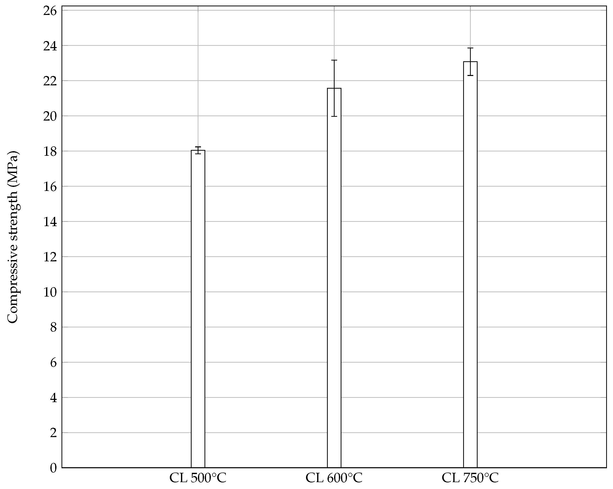
Figure 6.
Evolution compressive strength of calcined laterite blended cement pastes containing 100, 40, 30, 20 weight percent cement with similar workability at 1day, 7 days and 28 days of curing.
Figure 6.
Evolution compressive strength of calcined laterite blended cement pastes containing 100, 40, 30, 20 weight percent cement with similar workability at 1day, 7 days and 28 days of curing.
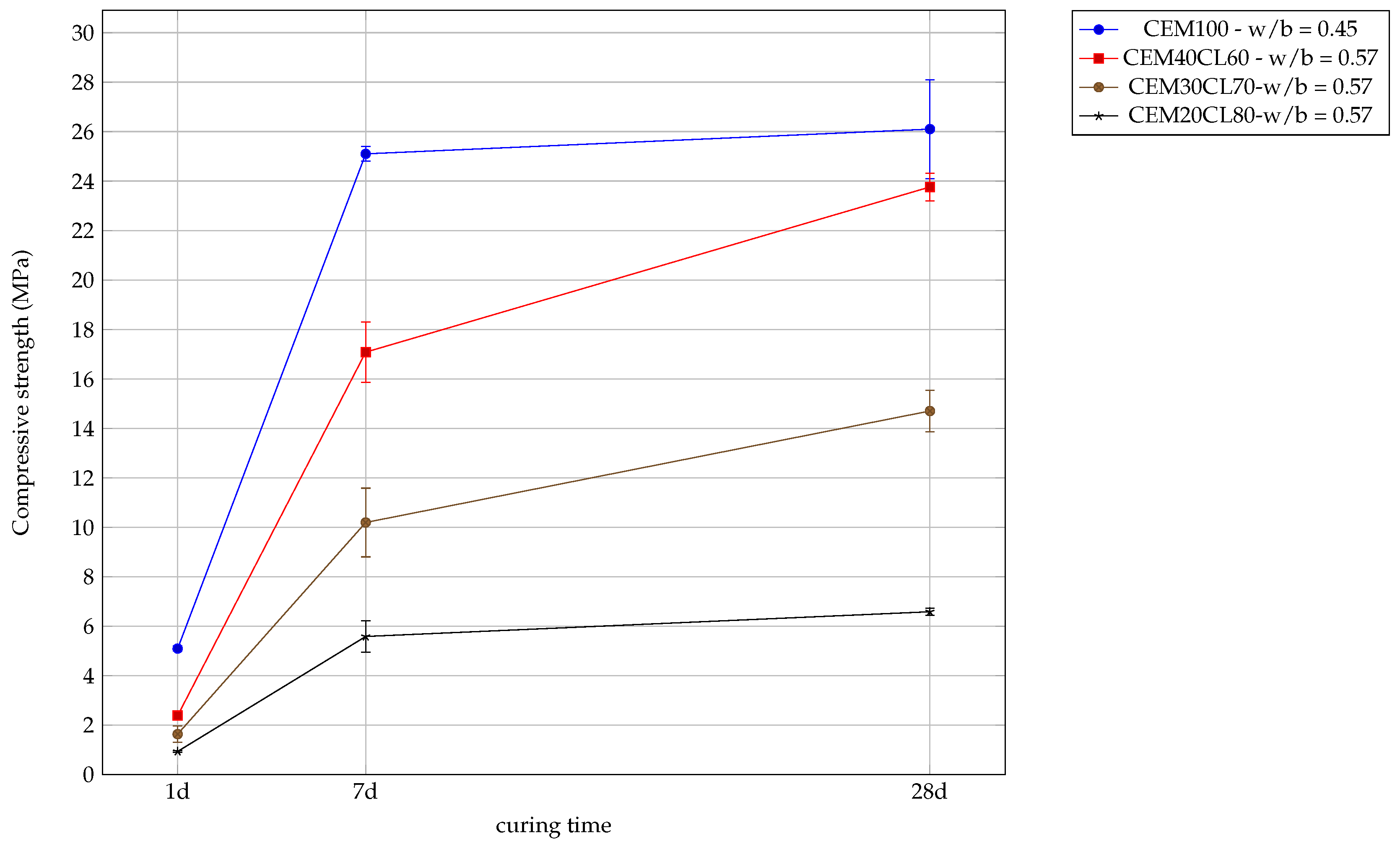
Figure 7.
XRD curves of calcined laterite blended cement- with cement ratio varying between and
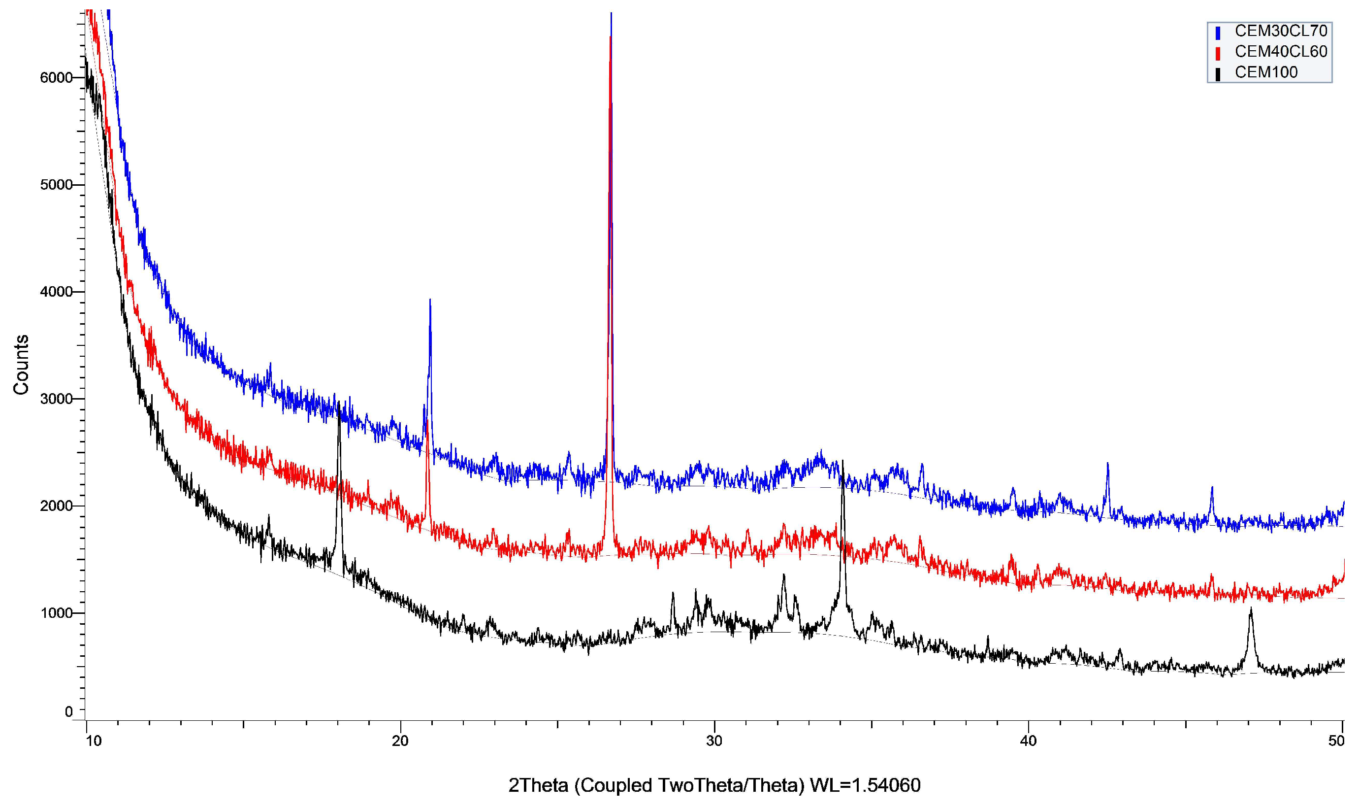
Figure 8.
Compressive strength measured after 1 day (a) and 28 days (b) of curing for the following blends: 100% CEM - LAT60/40 and 40% CEM - LAT60/40. For both blends e/l = 1.35
Figure 8.
Compressive strength measured after 1 day (a) and 28 days (b) of curing for the following blends: 100% CEM - LAT60/40 and 40% CEM - LAT60/40. For both blends e/l = 1.35
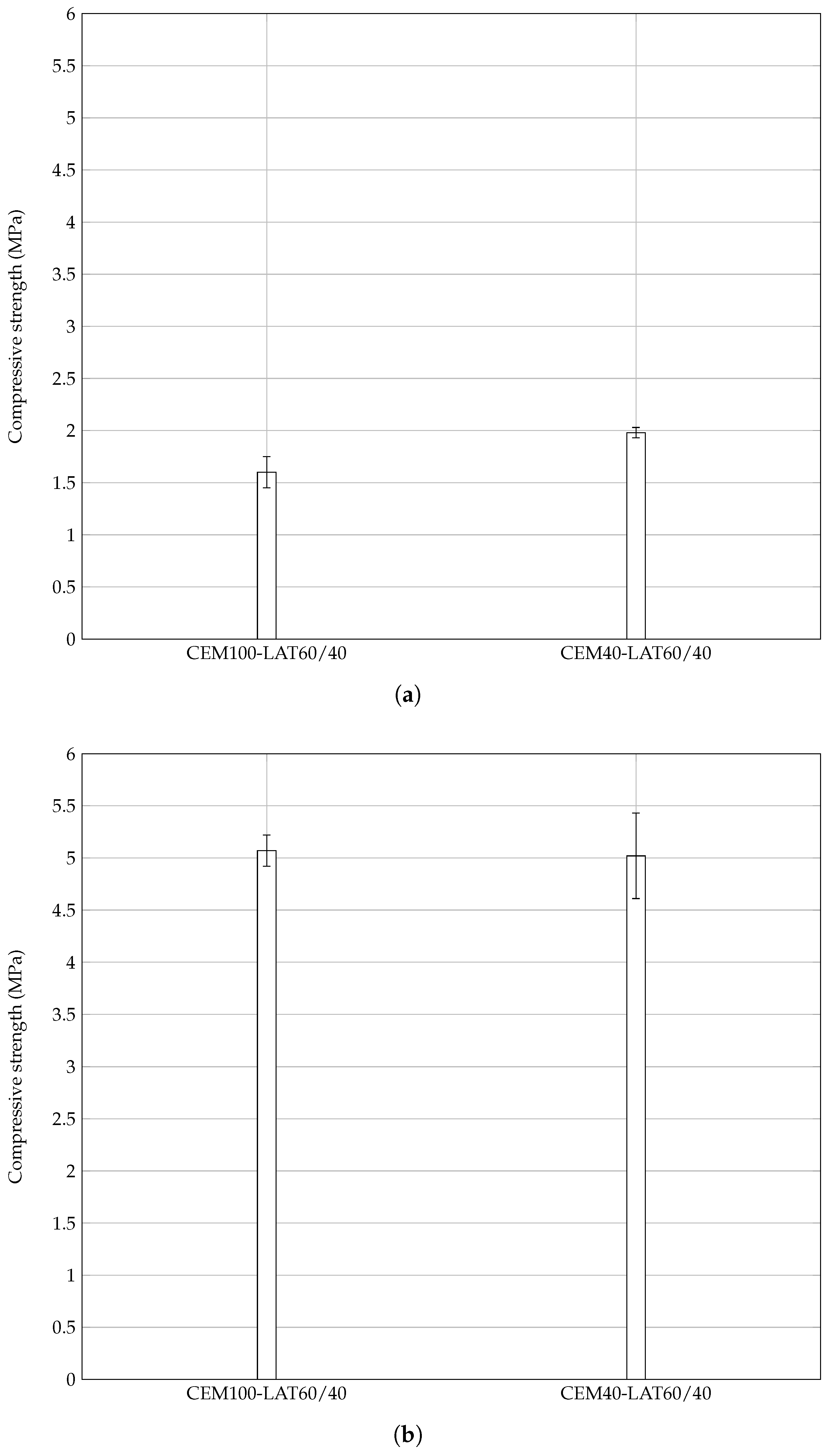
Figure 9.
Compressive strength measured at 28 days curing for the following blends: 40 % CEM - LAT 70/30 - e/l = 1.98; 40% CEM - LAT60/40, - e/l = 1.35; 40% CEM - LAT0/100 - e/l = 0.88
Figure 9.
Compressive strength measured at 28 days curing for the following blends: 40 % CEM - LAT 70/30 - e/l = 1.98; 40% CEM - LAT60/40, - e/l = 1.35; 40% CEM - LAT0/100 - e/l = 0.88
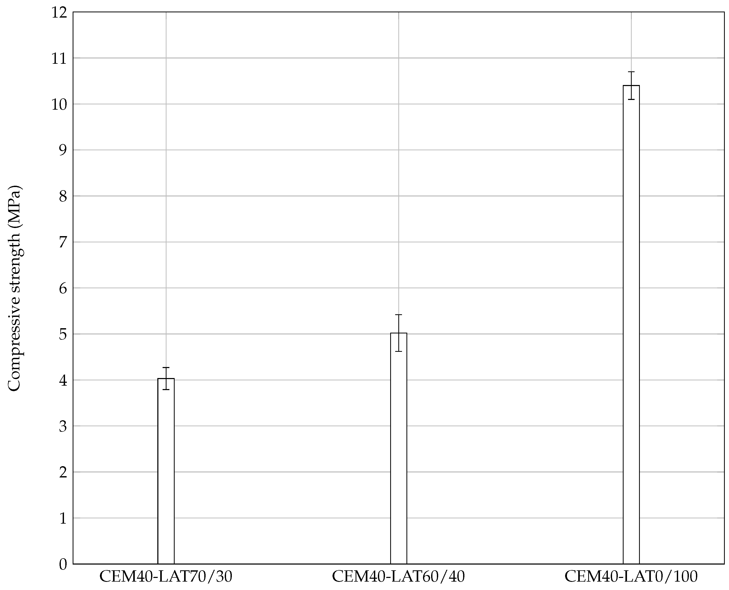
Figure 10.
Compressive strength measured after 7 and 28 days of curing for the following blends: 75 % CEM - 25% limestone filler - e/l = 0.345; 75% CEM - 25% mortar fines - e/l = 0.345; 75% lime - 25% mortar fines - e/l = 0.5
Figure 10.
Compressive strength measured after 7 and 28 days of curing for the following blends: 75 % CEM - 25% limestone filler - e/l = 0.345; 75% CEM - 25% mortar fines - e/l = 0.345; 75% lime - 25% mortar fines - e/l = 0.5
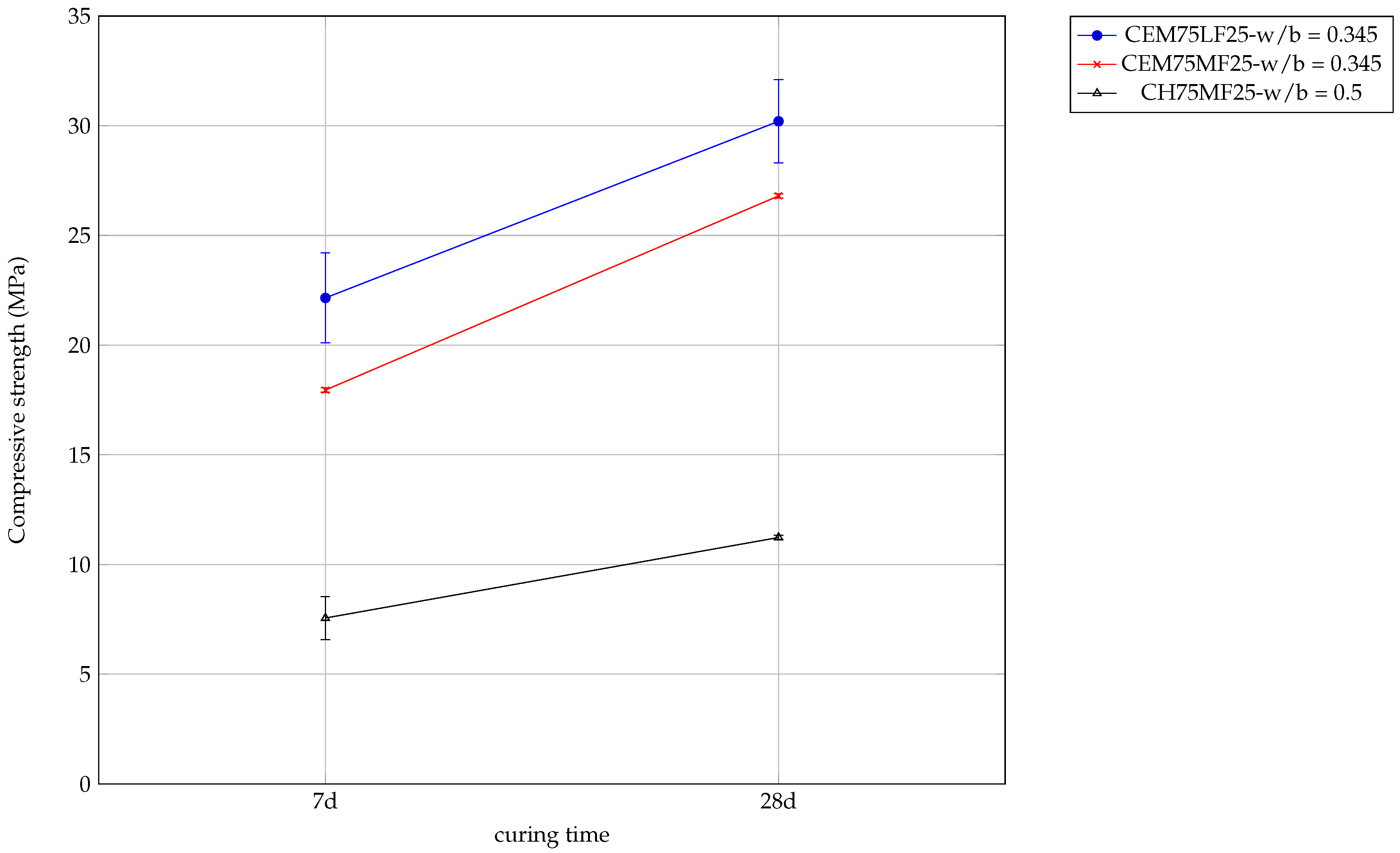
Figure 11.
XRD patterns of the following blends: 75% CEM and 25% LF - w/b = 0.345, 75% CEM and 25% MF - w/b = 0.345 and 75% CH and 25% MF - w/b = 0.5
Figure 11.
XRD patterns of the following blends: 75% CEM and 25% LF - w/b = 0.345, 75% CEM and 25% MF - w/b = 0.345 and 75% CH and 25% MF - w/b = 0.5
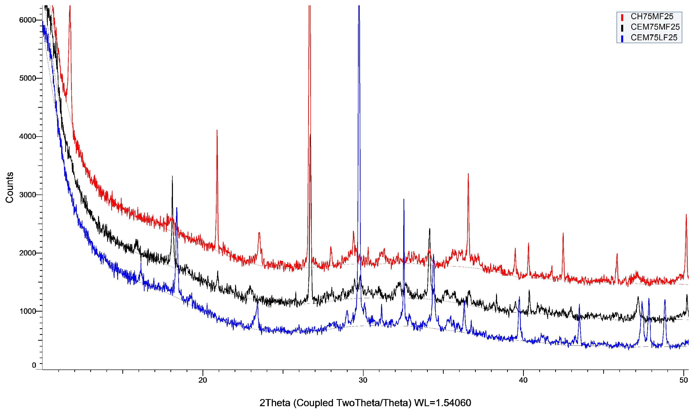
Figure 12.
DTG curves of the following blends: 75% CEM and 25% LF - w/b = 0.345, 75% CEM and 25% MF - w/b = 0.345 and 75% CH and 25% MF - w/b = 0.5
Figure 12.
DTG curves of the following blends: 75% CEM and 25% LF - w/b = 0.345, 75% CEM and 25% MF - w/b = 0.345 and 75% CH and 25% MF - w/b = 0.5
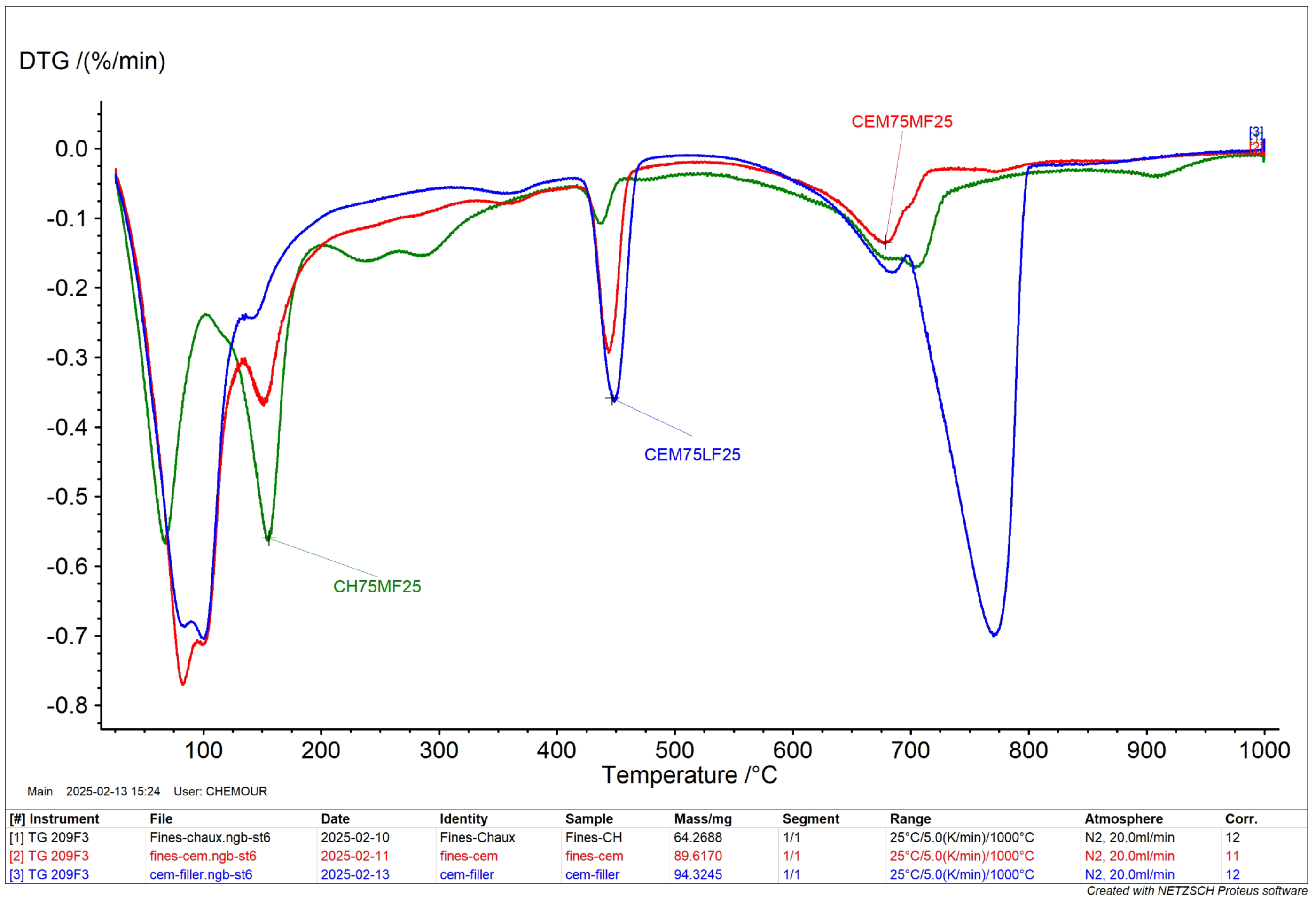
Figure 13.
Compressive strength of grinded mortar stabilised with hydrated lime, with water/solid ratio of 0.30, measured at 7 and 28 days of curing
Figure 13.
Compressive strength of grinded mortar stabilised with hydrated lime, with water/solid ratio of 0.30, measured at 7 and 28 days of curing
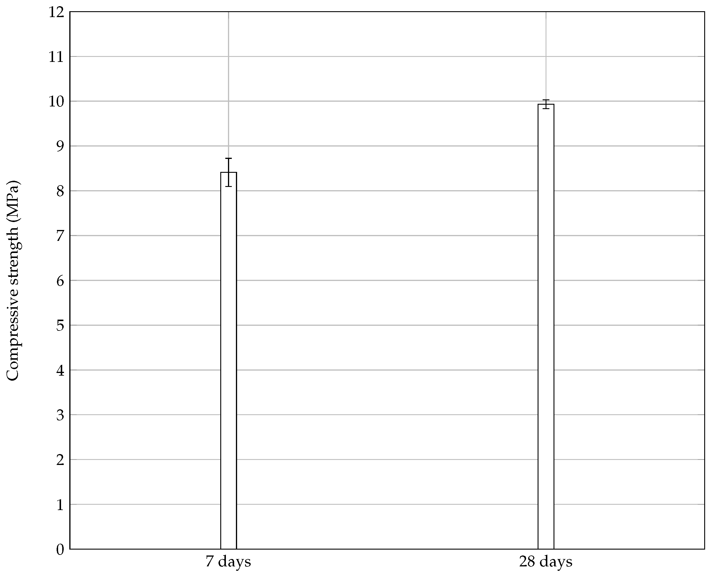
Figure 14.
Life cycle of the developed rendering mortar
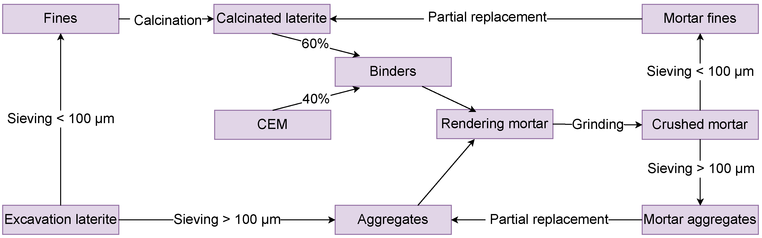

Table 1.
% composition by mass of binder pastes
| label | CEM II | calcined laterite | w/b |
| CEM100 | 100 | 0 | 0.45 |
| CEM20CL80 | 20 | 80 | 0.57 |
| CEM30CL70 | 30 | 70 | 0.57 |
| CEM40CL60 | 40 | 60 | 0.57 |
Table 2.
% Mortar pastes description.
| Label | Binder % weight composition | Lateritic sand granulometry (% particule size distribution) | w/b | ||
| CEM II | Calcined laterite | ||||
| CEM100-LAT 60/40 | 100 | 0 | 60 | 40 | 1.35 |
| CEM40- LAT 60/40 | 40 | 60 | 60 | 40 | 1.35 |
| CEM40- LAT 70/30 | 40 | 60 | 70 | 30 | 1.98 |
| CEM40- LAT 0/100 | 40 | 60 | 0 | 100 | 0.88 |
Table 3.
XRF analysis of raw materials - percent oxide composition by mass
| CL | |||||||||||
| CEM | 0.43 |
Table 4.
Water absorption by capillarity coefficient measured for the following mortar formulations: 100% CEM - LAT60/40, e/l = 1.35; 40% CEM - LAT60/40, e/l = 1.35; 40 % CEM - LAT 70/30 - e/l = 1.98; 40% CEM - LAT0/100, - e/l = 0.88
Table 4.
Water absorption by capillarity coefficient measured for the following mortar formulations: 100% CEM - LAT60/40, e/l = 1.35; 40% CEM - LAT60/40, e/l = 1.35; 40 % CEM - LAT 70/30 - e/l = 1.98; 40% CEM - LAT0/100, - e/l = 0.88
| Water absorption by capillarity coefficient | |
| CEM100-LAT40/60 | 0.011 |
| CEM40-LAT30/70 | 0.026 |
| CEM40-LAT40/60 | 0.039 |
| CEM40-LAT100/0 | 0.051 |
Disclaimer/Publisher’s Note: The statements, opinions and data contained in all publications are solely those of the individual author(s) and contributor(s) and not of MDPI and/or the editor(s). MDPI and/or the editor(s) disclaim responsibility for any injury to people or property resulting from any ideas, methods, instructions or products referred to in the content. |
© 2025 by the authors. Licensee MDPI, Basel, Switzerland. This article is an open access article distributed under the terms and conditions of the Creative Commons Attribution (CC BY) license (http://creativecommons.org/licenses/by/4.0/).
Copyright: This open access article is published under a Creative Commons CC BY 4.0 license, which permit the free download, distribution, and reuse, provided that the author and preprint are cited in any reuse.