

Submitted:
16 May 2025
Posted:
16 May 2025
You are already at the latest version
Abstract
An improved design of compact metasurface embedded MIMO Monopole antenna in ultra-wideband range is projected for band rejection purpose. Two alike antennas energized by two microstrips are the main part of this MIMO design. Periodic placement of square shaped metamaterial on the radiation plane improves the gain of the antenna. The gain improves significantly compared to normal antenna due to metamaterial. Notch frequency is realized by using L-shapedλ/4 spur line on each feed part .The intended antenna provides reflection coefficient well below -10 dB throughout the UWB range. A peak frequency notch at 5.5 GHz is considered to reject it from 5-6GHz WLAN band. Results achieved from simulation of the fabricated prototype were experimentally verified concerning impedance, gain and radiation characteristics.
Keywords:
Diversity
; Gain
; ECC
; Frequency notch
; Meta surface
; MIMO
; Spur line
1. Introduction
Since February 2002 there were considerable progress in UWB technology when FCC declared commercial usage of this UWB technology , 3.1 GHz to 10.6 GHz [1] with some power constraint. After that, UWB technology has quickly advanced, becoming a promising option for high-speed wireless communication in many applications.Interference of narrow bands like FBWA- 3.15 GHz, WLAN ( 5.15-8.15) GHz andX-band satellite (7.25-7.75 GHz ) downlink is a big problem. There are various filtering technique introduced to avoid this interference [2,3,4].
Latterly, MIMO has shown immense prospective to intensify the data rate further. This strengthen the channel capacity considerably by using multiple antennas. MIMO builds a more established connection and reduced congestion.
Here a simple and new improved method for designing MIMO antenna with square shaped meta material on the same plane of radiating patch and spur line on the feeding part .Few MIMO antennas were introduced in [3,4,5,6] and [10,11,13].Here novelty is, i) improvement of the gain by introducing meta surface structure ii) desired reflection coefficient and low mutual coupling and ii) simple filter for WLAN band rejection.
2. Antenna Design
Figure 1 depicts a compact MIMO antenna with meta-surface integrated frequency-notch functionality. A stub with dimension Wst x Lst is used for isolation. Here monopole antenna with circular shape and a fed of 50 Ohm micro strip line with dimension Wm x (LG+t) [4] is used as the radiator .A spur line of length lvs and width Ws is entrenched on the feed part of the antenna. The design parameters are given in Table 1.
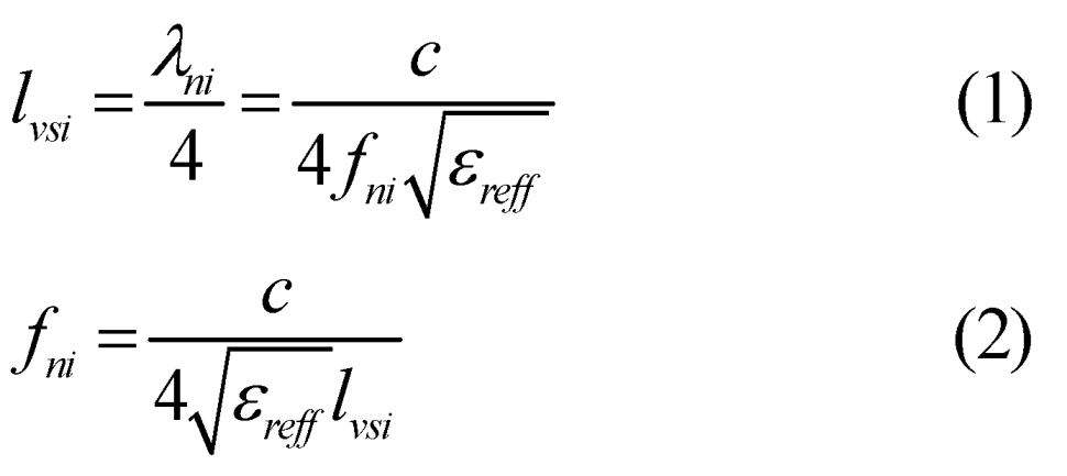
Where εreff is the effective dielectric constant. The upper and lower view of the fabricated antenna are shown in Figure 2a,b, respectively.
Figure 3 shows equivalent circuit of one antenna where Ra is corresponding radiation resistance of the antenna and La and Ca represent inductance and capacitance. Ya =Ga+jBa is the admittance of the monopole antenna where, Ga (real) and Ba (imaginary) admittance part .The metamaterial impedanceis Zss=Rss+jw Lss+1/jwCss..
Where Lssis the inductance corresponding to the length (hi=li ) of the square shaped meta-surface and Css is adjacent unit cell capacitance . Rss is the copper patch resistance.
3. Results and Discussion
The projected MIMO antenna is planned, simulated using [8] and measured within anechoic chamber. The antenna is meticulously examined for input impedance matching and radiation characteristics. Figure 4 depicts S11 and S22variation of the planned antenna. The projected MIMO encumbered with a spur line a separate frequency notch is observed at 5.63 GHz where simulated is 5.53 GHz. Figure 5 indicates the mutual coupling coefficient S21and S12 vs frequency. Basically ground stub improves the isolation between two antenna as revealed from coupling coefficient graph. Taking into consideration of satisfactory isolation and minimum perturbation of radiation pattern , the stub dimensions are chosen. From Figure 5 it is also clear that without stub very less isolation is achieved.
Figure 6 indicates variation of measured maximum realized gain. At notch frequency 5.63 GHz the gain drops to -10 dBi while for other frequency gain ranges from 3 to 6.2 dBi which is little bit higher than normal circular monopole antenna due to periodic placement of square shaped meta material on the radiating plane of the antenna. Radiation pattern at 3.5 GHz, 6.5 GHz and 7.5 GHz are shown in Figure 7. For E-plane, a null along the axis of the monopole (y-axis) is obtained and for H-plane nearly omni-directional pattern is obtained. The frequencies falls on UWB spectrum not including the notch frequency. Also novelty is enhancement of gain due to the periodic arrangement of square-shaped metasurface structures.
4. Diversity Analysis
This section focuses on analyzing various constraints related to dissimilar diversity concepts. In this study, parameters such as ECC, DG, MEG, and CCL are evaluated. The ECC parameter represents the correlation between the radiation patterns of multiple antennas operating simultaneously. Similarly, DG is a significant metric that provides insights into the effectiveness of diversity. The ECC, derived from S-parameters, can be computed using Equation [4], where Sii is the reflection coefficient, and Sij represents the mutual coupling between the two antenna ports. The relationship between ECC and DG is described by the following equations:
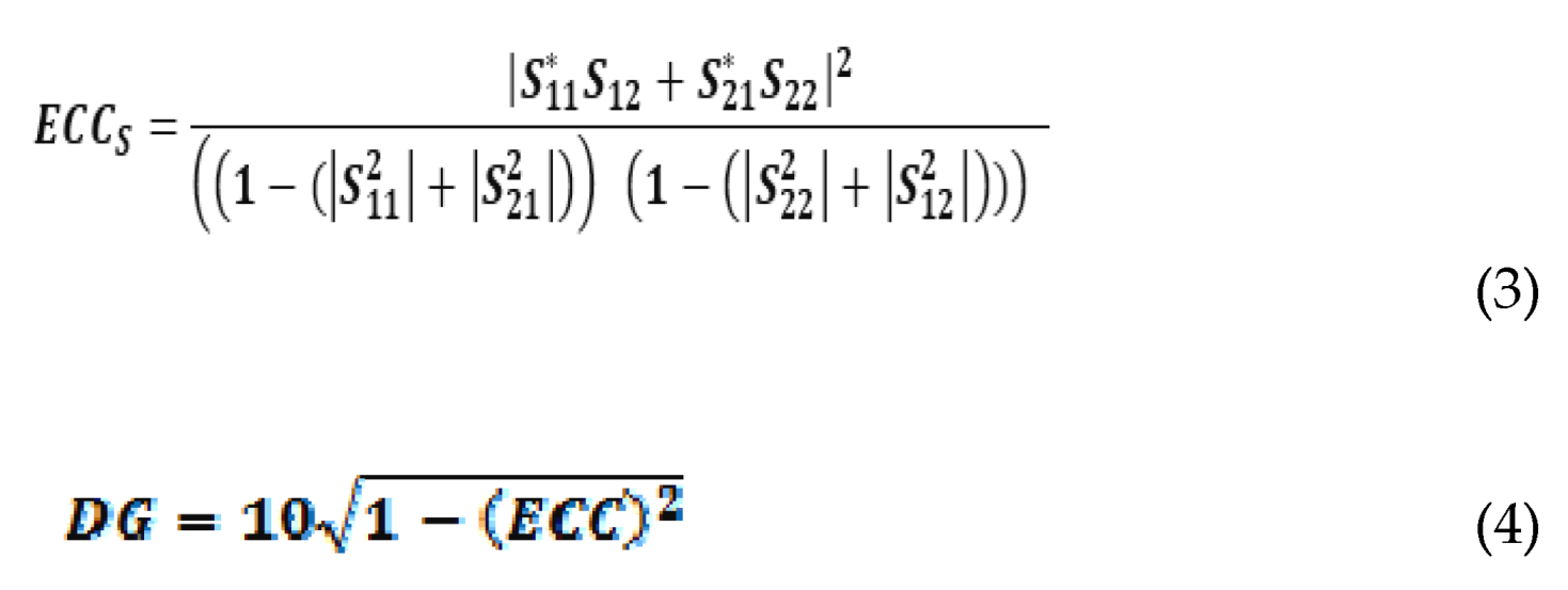
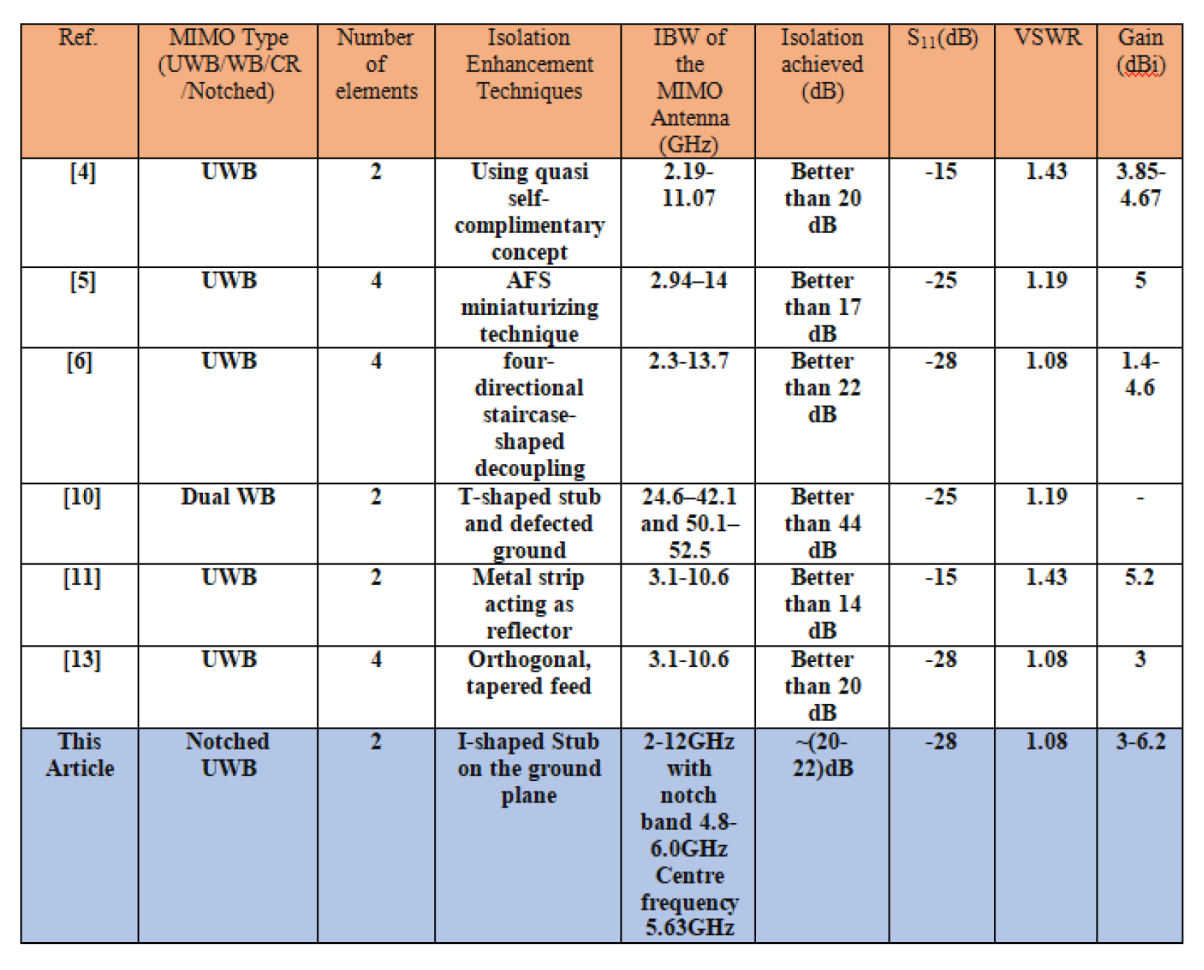
From Equation 3 and 4 ECC and DG are calculated and presented in Figure 8 and Figure 9, respectively. The analysis demonstrates excellent diversity performance, with ECC values remaining below 0.5 and diversity gain (DG) approximately 10 dB across the entire frequency range. Table 2 presents comparison table.
5. Conclusions
A new compact antenna design with two monopole elements and a band rejection feature for WLAN is presented. The unique feature of this design is the use of square-shaped meta-material to improve the antenna's performance. To reduce interference, a stub is placed between the two similar circular monopole antennas, which are powered by microstrip feeds. An L-shaped spur line on the microstrip feed helps block signals around 5.5 GHz. The design concept is carefully tested using advanced 3D simulation methods and accurate measurements.
Acknowledgments
Sajal Biring acknowledges financial support from National Science and Technology Council, Taiwan (NSTC 112-2221-E-131-008-MY2).
References
- The Federal Communications Commission (FCC) issued its initial guidelines for modifying Part 15 regulations concerning ultra-wideband (UWB) systems. Released in ET-Docket 98-153, 2002.
- Sarkar, C., Siddiqui, J.Y., Shaik, L.A., Saha, C., and Antar, Y.M.M. presented a low cross-polarized radiation balanced antipodal tapered slot antenna with frequency-notched characteristics. Published in IET Microwaves, Antennas & Propagation, Vol. 12, No. 11, pp. 1859–1863, May 2018.
- Liu, L., Cheung, S.W., and Yuk, T.I. designed a small-sized MIMO antenna tailored for UWB portable devices. Published in IEEE Transactions on Antennas and Propagation, Vol. 61, Issue 8, pp. 4257–4264, August 2013.
- Liu, X.L., Wang, Z.D., and Yin, Y.Z. proposed a compact UWB MIMO antenna employing QSCA technology to achieve superior isolation. Published in IEEE Antennas and Wireless Propagation Letters, Vol. 13, pp. 1497–1500, August 2014.
- Saad, A.A.R., and Mohamed, H.A. presented a compact four-element UWB MIMO slot antenna array. Published in IET Microwaves, Antennas & Propagation, Vol. 13, pp. 208–215, January 2019.
- Tang, Z., Wu, X., Zhan, J., Hu, S., Xi, Z., and Liu, Y. developed a compact UWB MIMO antenna integrating high isolation and triple-band rejection. Published in IEEE Access, Vol. 7, pp. 19856–19865, February 2019.
- Bahl, I., and Bhartia, P. authored the book Microwave Solid State Circuit Design. Published by Wiley, Hoboken, NJ, USA, 1998.
- High-Frequency Structure Simulator (HFSS), Version 14, developed by Ansys, is commonly utilized for electromagnetic simulations.
- Sharawi, M.S. authored Printed MIMO Antenna Engineering. Published by Artech House, Norwood, MA, USA, 2014.
- Madhav, T.P.B., Devi, U.Y., and Anilkumar, T. introduced a defected ground structure in a compact MIMO antenna to minimize mutual coupling for automotive communication systems. Published in Microwave and Optical Letters, Vol. 61, No. 3, pp. 1–7, December 2018.
- Roshna, T.K., Deepak, U., Sajitha, V.R., Vasudevan, K., and Mohanan, P. designed a UWB MIMO antenna with an integrated reflector to enhance isolation. Published in IEEE Transactions on Antennas and Propagation, Vol. 63, No. 4, pp. 1873–1877, April 2015.
- Sarkar, C., Saha, C., Shaik, L.A., Siddiqui, J.Y., and Antar, Y.M.M. proposed a monopole antenna integrated with spur lines for single, dual, and triple notch applications. Published in International Journal of RF and Microwave Computer-Aided Engineering, October 2019. [CrossRef]
- Kolangiammal, S., Balaji, L., and Mahdal, M. developed a four-element UWB MIMO antenna with orthogonal design and tapered feed for enhanced wireless communication. Published in Electronics (MDPI), September 2022. [CrossRef]
Figure 1.
Schematic of a microstrip fed L-shaped spur line resonator loaded proposed Antenna.
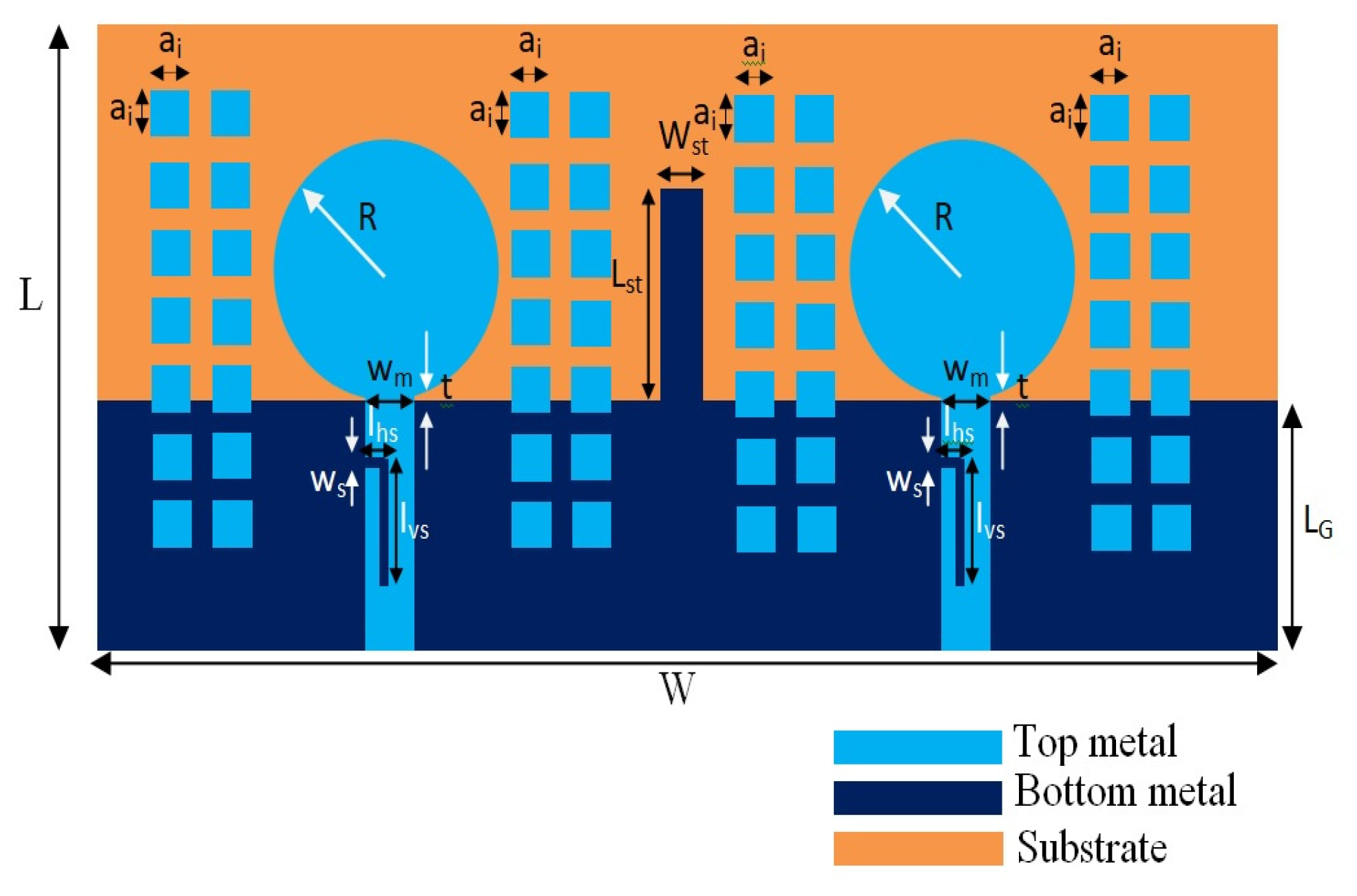
Figure 2.
Fabricated structure of Metamaterial implanted Monopole antenna (a) upper view (b) lower view.
Figure 2.
Fabricated structure of Metamaterial implanted Monopole antenna (a) upper view (b) lower view.

Figure 3.
Equivalent circuit of the planned antenna.

Figure 4.
Return loss Vs frequency Plot.
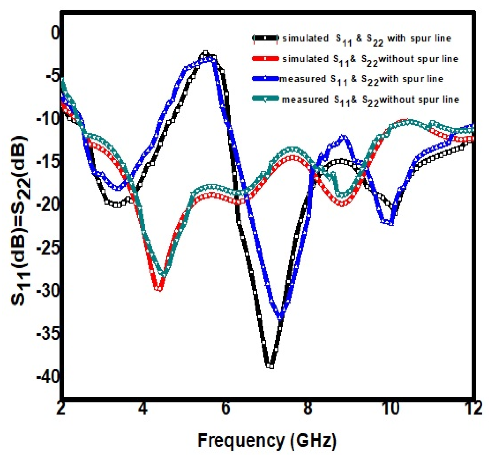
Figure 5.
Mutual coupling coefficient |S21| vs Frequency plot.
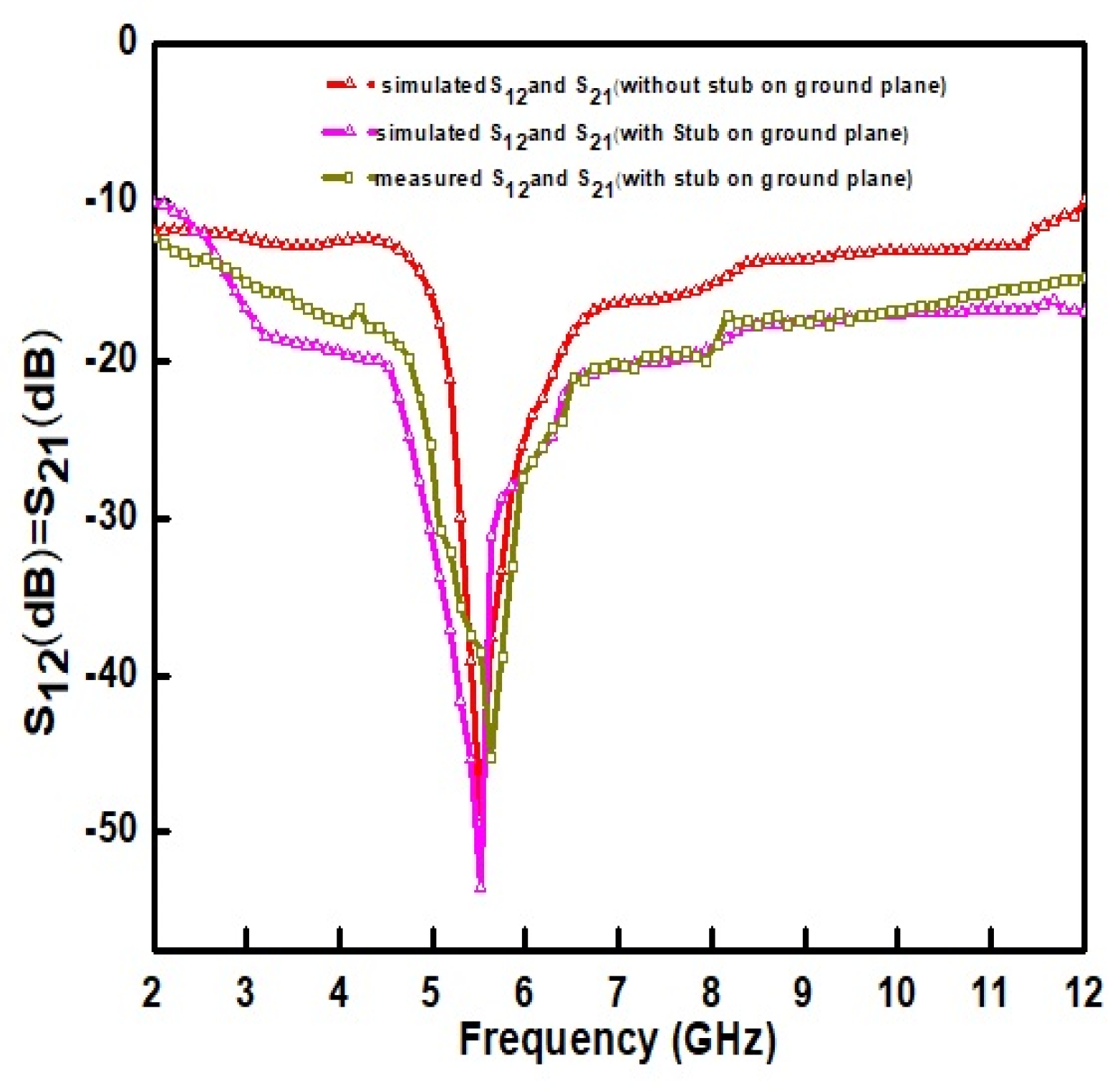
Figure 6.
Gain Vs frequency plot.
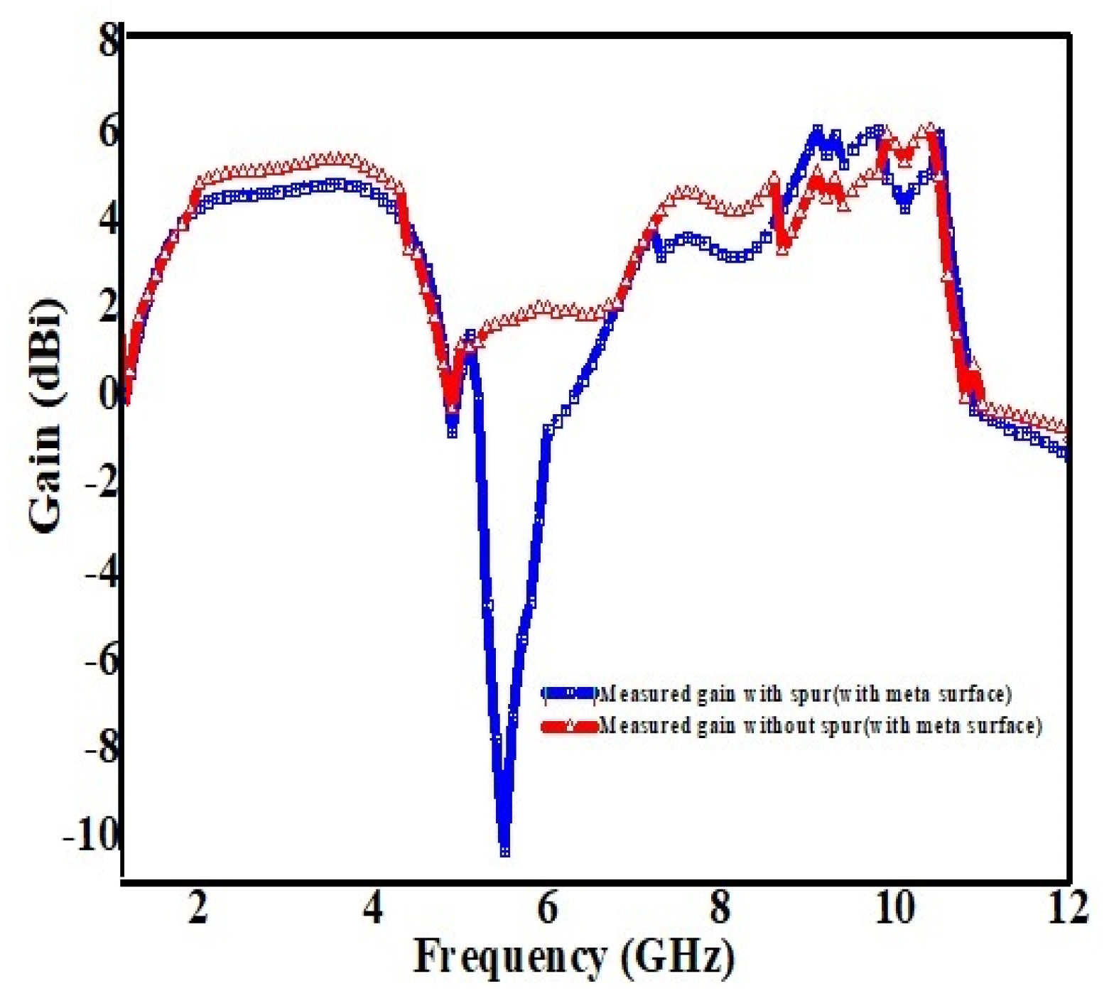
Figure 7.
Normalized (a) E (X-Y) and (b) H (X-Z) co-polarization radiation pattern.
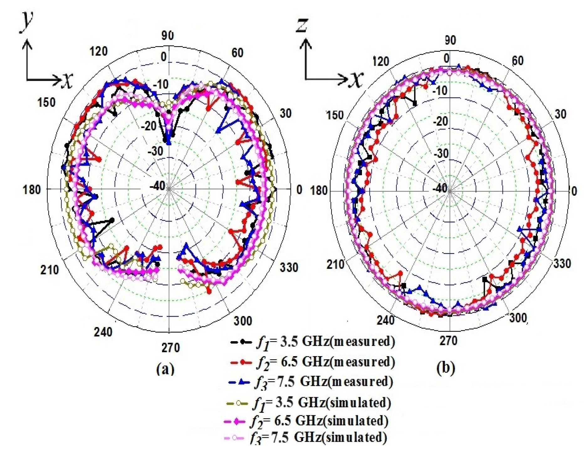
Figure 8.
Diversity gain Vs Frequency plot.

Figure 9.
ECC Vs Frequency plot.
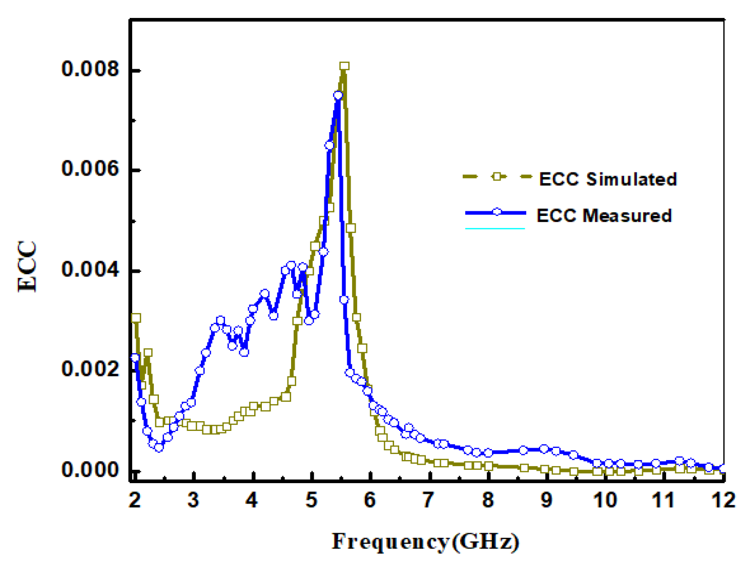

Table 1.
Design Parameters of the Antenna εr = 2.33, tan δ = 0.0012 and thickness h = 0.7875 mm.
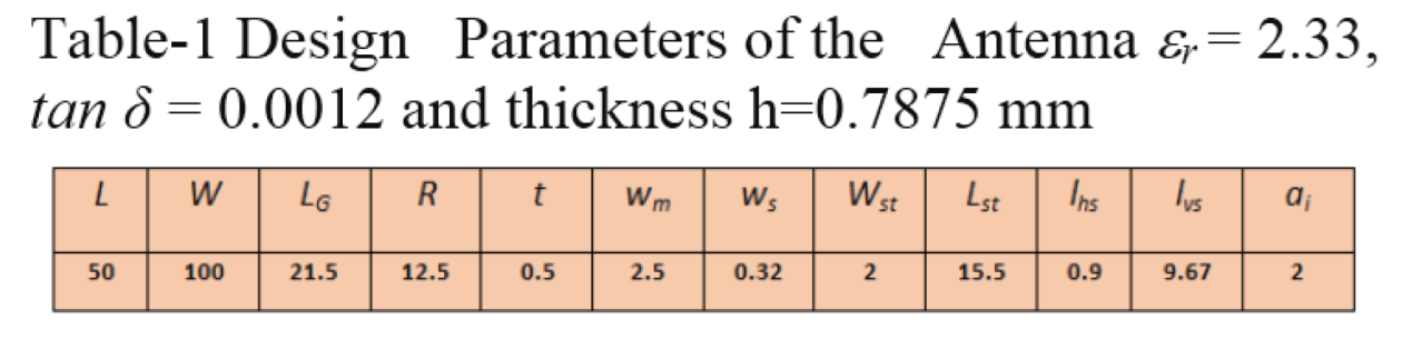 |
Table 2.
Comparison Table.
 |
Disclaimer/Publisher’s Note: The statements, opinions and data contained in all publications are solely those of the individual author(s) and contributor(s) and not of MDPI and/or the editor(s). MDPI and/or the editor(s) disclaim responsibility for any injury to people or property resulting from any ideas, methods, instructions or products referred to in the content. |
© 2025 by the authors. Licensee MDPI, Basel, Switzerland. This article is an open access article distributed under the terms and conditions of the Creative Commons Attribution (CC BY) license (http://creativecommons.org/licenses/by/4.0/).
Copyright: This open access article is published under a Creative Commons CC BY 4.0 license, which permit the free download, distribution, and reuse, provided that the author and preprint are cited in any reuse.