Submitted:
15 May 2025
Posted:
16 May 2025
You are already at the latest version
Abstract
The metal-organic framework UiO-66 is a material studied by molecular simulation for applications such as drug storage and contaminant adsorption, among other uses. Here, the implementation of the unit cell of UiO-66 is demonstrated for molecular dynamic simulations in the NAMD software using full-periodic and semi-periodic boundary conditions, with full detail for reproducibility. The method builds a PDB file (coordinates) from experimental data and a PFS file (structure) using Topotools for a given force field, with appropriate treatment of the periodic boundary conditions. Structural parameters of the material (lattice constant, internal bonds, angles, and dihedral angles) verify the implementation. For the semi-periodic system, lack of structure in the surface is detected compared to the bulk of the material.
Keywords:
UiO-66
; metal-organic frameworks
; unit cell
; molecular dynamics simulation
; NAMD
; Topotools
1. Introduction
Metal-organic frameworks (MOFs) are material hybrids that have garnered attention since their emergence in the 1990s due to their large surface areas, wide pore size range, and adjustable surface chemistry. They have applications in many areas: gas storage, adsorption, ion exchange, drug delivery, catalysis, etc. [1] MOFs are comprised of metallic ions (clusters) interconnected through organic molecules (linkers), a hybrid composition that offers such interesting inherent properties as robustness due to strong bonds, linkers modifiable by organic syntheses, and a well-defined geometric structure (MOFs are highly crystalline materials). [2] NanoMOFs (at least one dimension in nanometric scale) have been used in direct osmosis (e.g., UiO-66), reverse osmosis (e.g., MIL-125), nanofiltration (e.g., MOF-808) and ultrafiltration (e.g., MIL-101). For example, membranes with MOF-808 have a high adsorption capacity of and , but the presence of co-ions (, ) reduces the adsorption capacity without a full physicochemical understanding of the issue. [3] Advancing in the physicochemical understanding of molecule adsorption in nanoMOFs is fundamental to designing/modifying MOFs to improve applications, given that water quality for human consumption has decreased in recent decades. Understanding the arrangement of water molecules inside a MOF on a molecular scale is critical to analyzing the diffusion of solutes in applications where liquid water is present.
Computer simulation is a strategy for studying MOFs and their applications on the nanometer scale. [4,5,6,7,8,9,10,11,12,13] For example, Wehbe et al.[5] used molecular dynamics simulations to investigate the use of UiO-66 for the adsorption of lead ions from liquid water in the presence of . This kind of research normally uses two methods. On the one hand, molecular mechanics is used to study the movement, usually by molecular dynamics simulation (MD), of certain molecules of interest (ions, drugs) from and to the internal structure of the MOF in a solvent. On the other, quantum mechanics calculation (QM) is normally used to optimize molecular geometries of cluster and linker, define the necessary atomic charges, and to study the interaction between cluster and linker with molecules. Concerning the software used in molecular simulation of MOF, Figure 1 shows that Materials Studio [14] is the most used, which is a computer simulation suite capable of performing QM and MM; it must be noticed that many of the calculations with Materials Studio in MOF are QM. Gromacs and Lammps, both MD software, follow in their use. Conversely, the NAMD software [15] is not used; however, it is a powerful free MD software compatible with GPU devices (NVIDIA), fully compatible with the VMD software [16], and editable via Tcl commands. An extensive list and descriptions of the features of NAMD are given by Phillips et al.[17]. Then, there is an opportunity to spread the MD simulation of NanoMOFs to the community of NAMD users, which should increase research in this area. It is worth mentioning that Ortiz et al. [18] simulated the MOF ZIF8 using NAMD, which is likely the first MOF simulation with NAMD. However there are not details on how the files needed to reproduce the system simulated in NAMD were created.
One difficulty in implementing a MOF simulation is the production of the required files. NAMD requires the following: a PDB file (topology of the molecules), a PSF file (structure of the molecules), a force field file (bonded and non-bonded interaction parameters of the molecules), and a configuration file (NAMD parameters to run a simulation). As NAMD has been designed to simulate biomolecules, creating a PSF file is well-documented for molecules and can be achieved using the CHARM-GUI website [19] and the psfgen plugin [20] in the VMD software. However, there is no method for materials like MOFs. Moreover, a MOF is a fully bonded crystalline material, which increases the difficulties of implementation with periodic boundary conditions. This work presents a detailed method for implementing the unit cell of the MOF UiO-66 in NAMD for MD simulation with full-periodic and semi-periodic boundary conditions, contributing to the issue of reproducibility in computational science [21]. Structural parameters are analyzed for the full-periodic system to check the implementation. A discussion about the structure in the semi-periodic system highlights limitations on the surface in contrast to the bulk of the UiO-66. Finally, the method is applied to the structure of UiO-66-.
2. Materials and Methods
PBD and PSF files are highly structured and must match the atom names declared in the force field file. Also, atom types in the PSF file must match the declaration of types in the force field file. Finally, the bonds and angles defined in the PSF file must include the part of the structure (pairs of atoms) that should continue through the border of the simulations box (to handle the periodic boundary conditions in the simulation). Figure 2 summarizes the steps taken to build the PDB and PSF files for a UiO-66 cell in a periodic box. To ensure reproducibility, all files necessary for executing a unit cell full-periodic simulation are provided as supporting information.
- STEP ONE: The method begins with a search in the Cambridge Crystallographic Data Centre (CCDC) [22] for an experimental crystallographic information file (CIF); the identifier 733458 was used in this case. From the CIF, a “motif” was identified in the first step, defined as the PDB file residue. The choice of residue was made to facilitate the creation of the crystal structure (Fm-3m) in the fcc lattice, avoiding the duplication of atoms during unit cell formation.
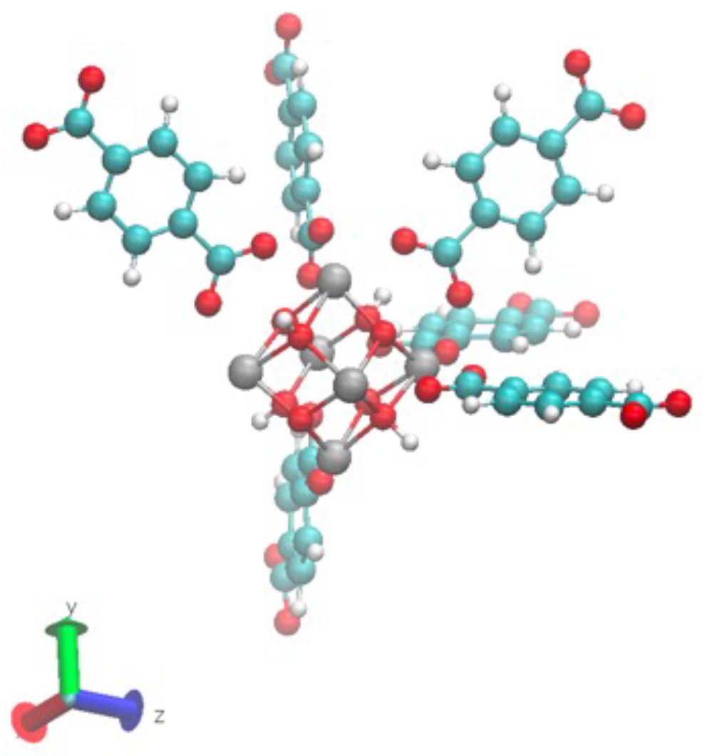
- STEP TWO: The motif was made by hand using VESTA [23] to open the CIF file and export it to an XYZ file, Avogadro [24] to open the XYZ file to build the motif and add hydrogens, and a text editor to assign different atom names to each atom in the motif to link the information with the force field and the PSF file. The result of this step is shown in Figure 3. The force field file, which is called par_file.inp in Figure 2, defines the atom types and was also created in this step. The connections between atom names and atom types were made in step four.
Figure 3.
(orthographic view) Residue defined to build the unit cell: motif.xyz. Carbon (green), oxygen (red), zirconium (gray), and hydrogen (white). VMD automatically adds bonds to the view, but there are no bonds in this structure. It is the file motif.xyz in Figure 2.
Figure 3.
(orthographic view) Residue defined to build the unit cell: motif.xyz. Carbon (green), oxygen (red), zirconium (gray), and hydrogen (white). VMD automatically adds bonds to the view, but there are no bonds in this structure. It is the file motif.xyz in Figure 2.
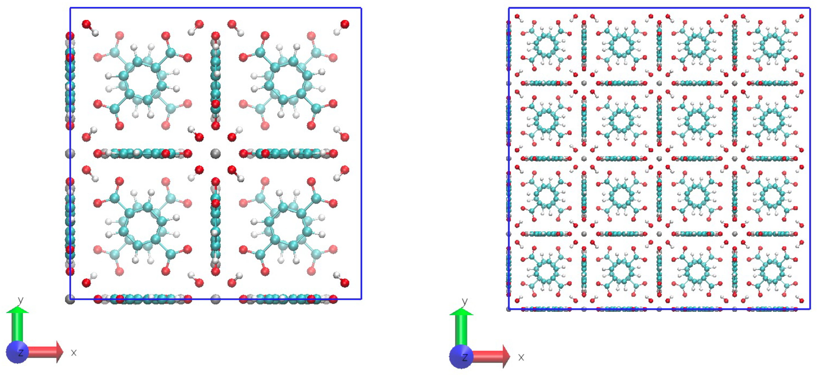
- STEP THREE: The unit cell of the UiO-66 was created with a homemade code by repeating the motif in the face-centered-cubic lattice. Here, a super cell of 2x2x2 unit cells was created and it was cut to fix it in a periodic box. Examples of the system are in Figure 4. Another homemade code was made to identify the pairs of atoms that must bond through the periodic boundary conditions to maintain the crystal structure. This resulted in a list of pairs of atoms, called pbc_bonds.tcl in Figure 2 to be read in the following step. This part must be clear whether the structure will be full-periodic (x, y, z) or semi-periodic (x, y) to build the appropriate list of atoms.
Figure 4.
(orthographic view) Unit cell (left) and 2x2x2 cell system (right). VMD automatically adds bonds to the view, but there are no bonds in this structure. Bonds (as well as angles and dihedrals) will be added when the PSF file is loading. It is the file unitcell.pdb in Figure 2.
Figure 4.
(orthographic view) Unit cell (left) and 2x2x2 cell system (right). VMD automatically adds bonds to the view, but there are no bonds in this structure. Bonds (as well as angles and dihedrals) will be added when the PSF file is loading. It is the file unitcell.pdb in Figure 2.
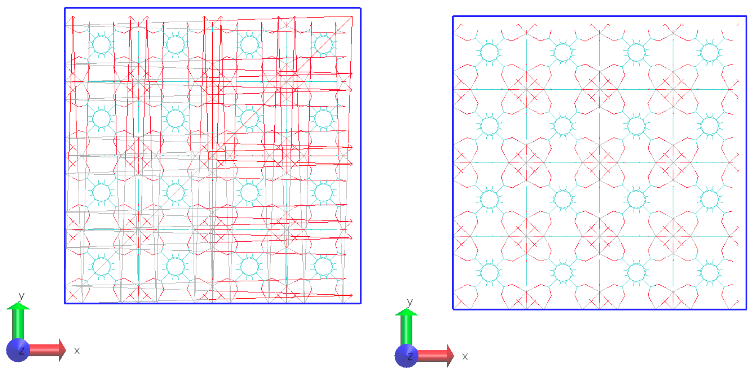
- STEP FOUR: The PSF file was created using the Topotools plugin [25] on VMD. The Topotools script defines the atom name, atom type, charge, and mass for each atom in the motif. Also, Topotools detects the bonds, angles, dihedrals, and impropers, including the list of pairs of atoms connected through the periodic boundary conditions. The PSF file connects pairs of atoms within the periodic boundary, rendering it unsuitable for visualizing snapshots, as the VMD would display connections with the periodic images of the system, resulting in numerous bonds spanning the box from side to side. For visualization, a second PSF file must be built, but not including the list of pairs of atoms from step three. Figure 5 shows the same system with the PSF file for calculation and visualization.
Figure 5.
(orthographic view) 2x2x2 cell periodic system: PSF including the connections through the PBC for MD calculations (left) and PSF for visualization (right).
Figure 5.
(orthographic view) 2x2x2 cell periodic system: PSF including the connections through the PBC for MD calculations (left) and PSF for visualization (right).
- STEP FIVE: The configuration file, called MD.conf in Figure 2, is created according to the desired kind of simulation, following the instructions in the NAMD user manual. At this point, it is important for the electrostatic treatment for the full-periodic system to use the PME (Particle Mesh Ewald) method and the semi-periodic system to use the MSM (Multilevel Summation Method). As in step four, Topotools automatically detects dihedrals and impropers, most of which may not be defined in the force field. When running NAMD, the software displays a message that a dihedral (or improper) has no defined parameters, and the atom type of the dihedral is reported. The solution is simple: each dihedral reported by NAMD must be included in the Force Field file with a constant force equal to zero.
Calculations: The force field of Zhang et al. [11] was implemented to simulate the structure of the hydroxylated UiO-66. Calculations were done with NAMD version 3.0b4 for Linux-x86_ 64-multicore-CUDA. [26] The cutoff was 10 A, the time step was 0.5 fs, the van der Waals exclusion scaled1-4 was used with 1-4scaling equal 0; the electrostatic force calculation was made with PME (for full-periodic boundary conditions) and MSM (for semi-periodic boundary conditions). The Langevin thermostat was used (Damping 1.0 1/ps) as well as the Langevin barostat (period 100 ps, decay 20 ps). VMD version 1.9.4a55 [27] was used to analyze the results and snapshot of the coordinates.
3. Results
The NPT simulation at 100 K and 1 bar, after 0.5 ns, gives a length cell of 20.62 Å, very near the experimental value (CIF file, 20.74 Å). Table 1 shows other structural results describing the linker and cluster connection.
Atom types are shown in Figure 6. The ZR-O1 bond is near the equilibrium parameter on the force field (2.214 Å); the angle O1-ZR-O1 is also near the equilibrium parameter on the force field (73.53°). However, the dihedral ZR-O1-C1-C2 is particularly noteworthy because it has not been defined in the force field yet based on the structure in the CIF file, it should be 180°. These results indicate that the simulation accurately represents the structure of the material. Thus, the method implemented to build and simulate the MOF is correct. A simulation at high temperatures (350 K and 1 atm) was made to check the stability of the model. The structural parameters are also in Table 1. There are no significant changes in the mean values, but the min and max values show that the material is more flexible than the case at 100 K, as expected.
A semi-periodic system is needed to consider simulations of UiO-66 with solutions (brines, wastewater, gas mixtures, etc.). In this system, periodic boundary conditions apply in the directions x and y, while it is free in the direction z. The few studies that show the interface used in the simulations with UiO-66 have not implemented a real type of surface. Instead, the surface is created by splitting the unit cell in some part (see, for instance, Whebe et al.). This procedure creates two surfaces in the material, S1 and S2, as Figure 7-(a) shows for the semi-periodic model.
Table 2 compares some structural parameters for atoms in the bulk of the material and atoms on surface S1 after 0.5 ns of NVT simulation at 100 K. These results show the surface lost structure compared to the bulk in terms of the angle O1-ZR-O1 and particularly the dihedrals ZR-O1-C1-C2 and O1-C1-C2-C2. It is a collapse of the surface, shown in Figure 7-(b).

Table 2.
Structural results of the UiO-66. Semi-periodic system at 100 K.
| Bulk | Surface | |||||
|---|---|---|---|---|---|---|
| Mean | Min | Max | Mean | Min | Max | |
| Bond ZR-O1 (Å) | 2.256 | 2.219 | 2.294 | 2.234 | 2.197 | 2.272 |
| Angle O1-ZR-O1 (degree) | 66.96 | 63.48 | 70.62 | 59.34 | 56.32 | 62.99 |
| Dihedral ZR-O1-C1-C2 (degree) | 176.25 | 165.66 | 179.99 | 161.17 | 147.49 | 178.53 |
| Dihedral O1-C1-C2-C2 (degree) | 174.09 | 157.42 | 179.96 | -86.16 | -102.71 | -74.05 |
To correct the wrong behavior of the surface S1, here recognized as the lack of crystal structure in the surface, the force field should include additional parameters for the dihedral ZR-O1-C1-C2 (the dihedral O1-C1-C2-C2 has values in the force field). To check, the values of Yang et al.[4] for this dihedral were included in the force field, and the MD was repeated, with results in Table 3. In this case, the surface increased structure for the dihedral ZR-O1-C1-C2 looks better than in the previous case; however, the defect in the dihedral O1-C1-C2-C2 remains, as Figure 7-(c) shows. In a final attempt, the force constant for the dihedral O1-C1-C2-C2 was increased 10 times to verify if surface S1 increased the structure. Figure 7-(d). shows better behavior than the previous cases, but it cannot be considered a solution because, at the same time, the bulk of the UiO-66 lost flexibility, and according to Babarao et al.[8], the flexibility of the MOF could influence the dynamics of molecules. Surface S2 did not show any structural defects for the evaluated parameters, which is interesting. In some papers where a snapshot of the UiO-66 is given it is possible to identify that all the borders of the MOF are the same surface S2 (see for instance ref. [10,11,28]). In such cases (if the snapshot are correct) the material is not periodic and border effects could be introduced, however, as the surfaces can keep the structure, it may not represent an inconvenience from this point of view. Finally, the differences between S1 and S2 could arise in the fact that the each cluster in S2 has eight linkers, four connecting with clusters in the same surface and four connecting with clusters in the bulk; in surface S1 each cluster has only four linker connecting with clusters in the bulk, which demands more constraint in the force field to keep the structure.
Table 3.
Structural results of the UiO-66. Semi-periodic system at 100 K. Force field modify in the dihedral ZR-O1-C1-C2.
Table 3.
Structural results of the UiO-66. Semi-periodic system at 100 K. Force field modify in the dihedral ZR-O1-C1-C2.
| Bulk | Surface | |||||
|---|---|---|---|---|---|---|
| Mean | Min | Max | Mean | Min | Max | |
| Bond ZR-O1 (Å) | 2.257 | 2.210 | 2.293 | 2.260 | 2.219 | 2.298 |
| Angle O1-ZR-O1 (degree) | 66.94 | 63.88 | 69.92 | 60.47 | 58.13 | 63.67 |
| Dihedral ZR-O1-C1-C2 (degree) | 178.19 | 172.76 | 179.99 | 176.73 | 168.57 | 179.93 |
| Dihedral O1-C1-C2-C2 (degree) | 173.85 | 160.17 | 179.88 | 100.89 | 70.04 | 122.24 |
4. Discussion
The MOF UiO-66 can be used in several applications. One is the adsorption of contaminants in water (lead and arsenic, for example) thanks to the small pore size present in the structure of the UiO-66. From a physical chemistry point of view, it is fundamental to improve knowledge about the interaction of this MOF with different solutes at the nanoscale, such as how different ions in solution move into the MOF, compete, and are absorbed. A semi-periodic structure of the UiO-66 is a required step to simulate more realistic cases that will put the simulation results near the applications. However, these more realistic systems demand the creation of combined structures of UiO-66 with water (solvent) and ions. Fortunately, a PSF file can also be built, which will be included in an upcoming work. Liu et al. [29] have shown that the real surface of the UiO-66 can be cluster-terminated or linker-terminated. The results in Figure 7-(a) show that the surface S1 of the UiO-66 (which is a rough approach to the linker-terminated surface) requires a separate definition of parameters in the force field to retain crystal structure without affecting the bulk structure of the MOF; instead, surface S2 (which is a rough approach to the cluster-terminated surface) does not present the structure problems, and it is the option to use this system without father modifications in the force field. But certainly, a realistic surface of the UiO-66 is neither S1 nor S2. It is necessary to advance in models and force fields for real surfaces. In addition to opening the simulations of these kinds of materials in NAMD, the presented method for the implementation of the unit cell of MOF UiO-66 for MD simulations can be easily extended to other versions of UiO-66 (linker modify) simply by changing the motif in step two. Applying the method for more complex MOF, such as MIL-101, requires the capability to build the unit cell, which is a matter for an upcoming work. So, the method could be applied to any MOF by adjusting steps two and three. For example, the unit cell of the UiO-66- is built by editing the motif (step 2) and following the next steps of the method. Adding groups in the linker is a relatively easy task in AVOGADRO, but assigning atoms name and atoms type requires detail work because it will depend on the force field. In this case, the force field of Zhang et al. [11] was also used. However, the inclusion of groups in the linker produces changes in the charges of carbons in the aromatic ring (with respect to the carbons in the UiO-66) which demands more atoms name for the carbons in the force field. Figure 8 shows the motif for this case and the super cell generated. (PDB, PSF, and force field file are given in the supporting information). Applying MD at 100 K and 1 bar, structural parameters result similar to those reported in Figure 1.
5. Conclusions
The results showed that the unit cell can be implemented in NAMD for full-periodic and semi-periodic systems using a reproducible method. The structural parameters analyzed correspond with the crystallographic data (CIF file) and with the parameters of the force field used. The structure of the UiO-66 remains from 100 K to 350 K, the temperatures considered in this study. For the semi-periodic system, the surfaces of the material show structural differences, where the linker type surface is not appropriate due to the lack of structure. The method for implementing the unit cell of MOF UiO-66 for MD simulations can be readily adapted to different versions of UiO-66 with modified linkers, as was shown for UiO-66-, in addition to facilitating the simulations of such materials in NAMD. Extending the method will make it possible to include liquid water in the simulations to examine the behavior of water within the unit cell of the MOF, followed by the analysis of ion interactions, clarifying the physical chemistry aspects of the applications.
Supplementary Materials
The following supporting information can be downloaded at the website of this paper posted on Preprints.org.
Funding
This research was funded by ANID Fondecyt N°11230774 Chile.
Acknowledgments
The author thanks Martina Lessio and Jierui Zhang for their feedback on the parameters of the force field used in this work.
Conflicts of Interest
The author declare no conflicts of interest.
Abbreviations
The following abbreviations are used in this manuscript:
| MOF | Metal-organic framework |
| MD | Molecular dynamics |
| CIF | Crystal information file |
| PBD | Protein data bank file |
| PSF | Protein structure file |
References
- Cai, X.; Xie, Z.; Li, D.; Kassymova, M.; Zang, S.Q.; Jiang, H.L. Nano-sized metal-organic frameworks: Synthesis and applications. Coordination Chemistry Reviews 2020, 417, 213366. [Google Scholar] [CrossRef]
- Rowsell, J.L.C.; Yaghi, O.M. Metal–organic frameworks: a new class of porous materials. Microporous and Mesoporous Materials 2004, 73, 3–14. [Google Scholar] [CrossRef]
- Jun, B.M.; Al-Hamadani, Y.A.J.; Son, A.; Park, C.M.; Jang, M.; Jang, A.; Kim, N.C.; Yoon, Y. Applications of metal-organic framework based membranes in water purification: A review. Separation and Purification Technology 2020, 247, 116947. [Google Scholar] [CrossRef]
- Yang, Q.; Jobic, H.; Salles, F.; Kolokolov, D.; Guillerm, V.; Serre, C.; Maurin, G. Probing the Dynamics of CO2 and CH4 within the Porous Zirconium Terephthalate UiO-66(Zr): A Synergic Combination of Neutron Scattering Measurements and Molecular Simulations. Chemistry – A European Journal 2011, 17, 8882–8889. [Google Scholar] [CrossRef] [PubMed]
- Wehbe, M.; Abu Tarboush, B.J.; Shehadeh, M.; Ahmad, M. Molecular dynamics simulations of the removal of lead(II) from water using the UiO-66 metal-organic framework. Chemical Engineering Science 2020, 214, 115396. [Google Scholar] [CrossRef]
- Kotzabasaki, M.; Galdadas, I.; Tylianakis, E.; Klontzas, E.; Cournia, Z.; Froudakis, G.E. Multiscale simulations reveal IRMOF-74-III as a potent drug carrier for gemcitabine delivery. Journal of Materials Chemistry B 2017, 5, 3277–3282. [Google Scholar] [CrossRef] [PubMed]
- Gupta, K.M.; Zhang, K.; Jiang, J. Glucose recovery from aqueous solutions by adsorption in metal–organic framework MIL-101: a molecular simulation study. Scientific Reports 2015, 5, 12821. [Google Scholar] [CrossRef] [PubMed]
- Babarao, R.; Jiang, J. Unraveling the Energetics and Dynamics of Ibuprofen in Mesoporous Metal−Organic Frameworks. The Journal of Physical Chemistry C 2009, 113, 18287–18291. [Google Scholar] [CrossRef]
- Shu, N.; Wang, Z.; Hu, S.; Mou, Y.; Li, Z.; Lyu, Q. Effect of linker configuration and functionalization on the seawater desalination performance of Zr-MOF membrane. Chemical Physics Letters 2021, 780, 138949. [Google Scholar] [CrossRef]
- Boroushaki, T.; Dekamin, M.G.; Hashemianzadeh, S.M.; Naimi-Jamal, M.R.; Ganjali Koli, M. A molecular dynamic simulation study of anticancer agents and UiO-66 as a carrier in drug delivery systems. Journal of Molecular Graphics and Modelling 2022, 113, 108147. [Google Scholar] [CrossRef] [PubMed]
- Zhang, J.; Paesani, F.; Lessio, M. Computational insights into the interaction of water with the UiO-66 metal–organic framework and its functionalized derivatives. Journal of Materials Chemistry C 2023, 11, 10247–10258. [Google Scholar] [CrossRef]
- Shao, Y.; Fan, X.; Wang, S.; Huang, L.; Ju, S.; Li, W. Insights into adsorption and diffusion of CO2, CH4 and their mixture in MIL-101(Cr) via molecular simulation. Chemical Engineering Journal 2024, 480, 148215. [Google Scholar] [CrossRef]
- Mohmmad, A.; Mosavian, M.H.; Moosavi, F. Pharmaceutically active compounds removal from aqueous solutions by MIL-101(Cr)-NH2: A molecular dynamics study. Ecotoxicology and Environmental Safety 2024, 278, 116333. [Google Scholar] [CrossRef] [PubMed]
- Materials Studio. Available online: https://www.3ds.com/products/biovia/materials-studio.
- NAMD. Available online: https://www.ks.uiuc.edu/Research/namd/.
- VMD. Available online: https://www.ks.uiuc.edu/Research/vmd/.
- Phillips, J.C.; Braun, R.; Wang, W.; Gumbart, J.; Tajkhorshid, E.; Villa, E.; Chipot, C.; Skeel, R.D.; Kalé, L.; Schulten, K. Scalable molecular dynamics with NAMD. Journal of Computational Chemistry 2005, 26, 1781–1802. [Google Scholar] [CrossRef] [PubMed]
- Ortiz, A.U.; Boutin, A.; Fuchs, A.H.; Coudert, F.X. Investigating the Pressure-Induced Amorphization of Zeolitic Imidazolate Framework ZIF-8: Mechanical Instability Due to Shear Mode Softening. The Journal of Physical Chemistry Letters 2013, 4, 1861–1865. [Google Scholar] [CrossRef] [PubMed]
- CHARMM-GUI. Available online: https://charmm-gui.org.
- psfgen. Available online: https://www.ks.uiuc.edu/Research/vmd/plugins/psfgen/.
- Coudert, F.X. Reproducible Research in Computational Chemistry of Materials. Chemistry of Materials 2017, 29, 2615–2617. [Google Scholar] [CrossRef]
- CCDC. Available online: https://www.ccdc.cam.ac.uk/structures/.
- VESTA. Available online: https://jp-minerals.org/vesta/en/.
- AVOGADRO. Available online: https://www.openchemistry.org/projects/avogadro2/.
- Topotools. Available online: https://sites.google.com/site/akohlmey/software/topotools.
- Phillips, J.C.; Hardy, D.J.; Maia, J.D.C.; Stone, J.E.; Ribeiro, J.V.; Bernardi, R.C.; Buch, R.; Fiorin, G.; Hénin, J.; Jiang, W.; et al. Scalable Molecular Dynamics on CPU and GPU Architectures with NAMD. The Journal of Chemical Physics 2020, 153, 044130. [Google Scholar] [CrossRef] [PubMed]
- Humphrey, W.; Dalke, A.; Schulten, K. VMD: Visual Molecular Dynamics. Journal of Molecular Graphics 1996, 14, 33–38. [Google Scholar] [CrossRef] [PubMed]
- Wang, S.; Zhou, G.; Sun, Y.; Huang, L. A computational study of water in <span style="font-variant:small-caps;">UiO</span> -66 <span style="font-variant:small-caps;">Zr-MOFs</span> : Diffusion, hydrogen bonding network, and confinement effect. AIChE Journal 2021, 67, e17035. [Google Scholar] [CrossRef]
- Liu, L.; Zhang, D.; Zhu, Y.; Han, Y. Bulk and local structures of metal–organic frameworks unravelled by high-resolution electron microscopy. Communications Chemistry 2020, 3, 99. [Google Scholar] [CrossRef] [PubMed]
Figure 1.
Search results in Web of Science and Scopus with the keywords (All Fields): “metal-organic frameworks” and “materials studio”; “metal-organic frameworks” and “gromacs”; “metal-organic frameworks” and “lammps”; “metal-organic frameworks” and “namd”. Search date: May 15 (2025). The term “non-adiabatic molecular dynamic” (NAMD) was discarded because it is a method, not a software.
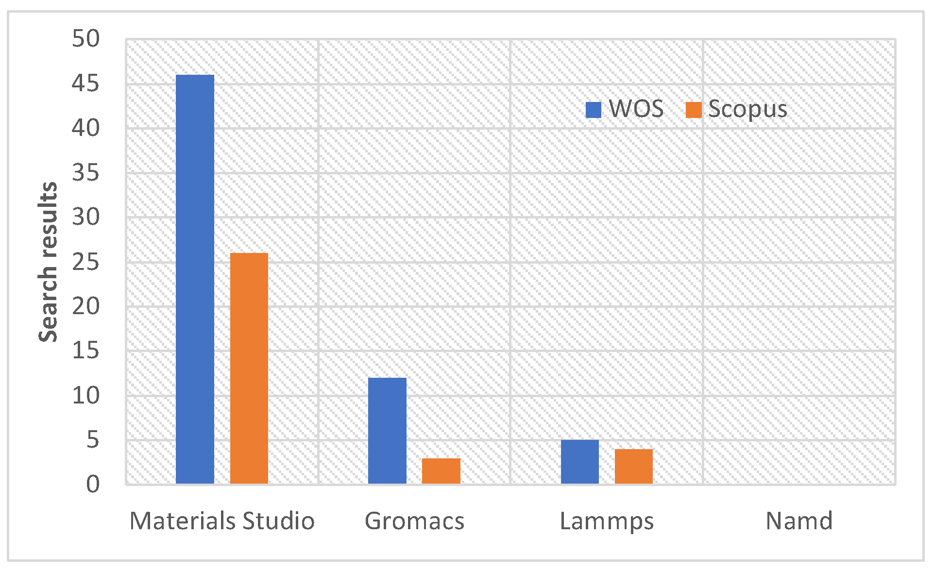
Figure 2.
Flow diagram to get the files for the MD simulation of the UiO-66 unit cell with periodic boundary conditions in NAMD.
Figure 2.
Flow diagram to get the files for the MD simulation of the UiO-66 unit cell with periodic boundary conditions in NAMD.
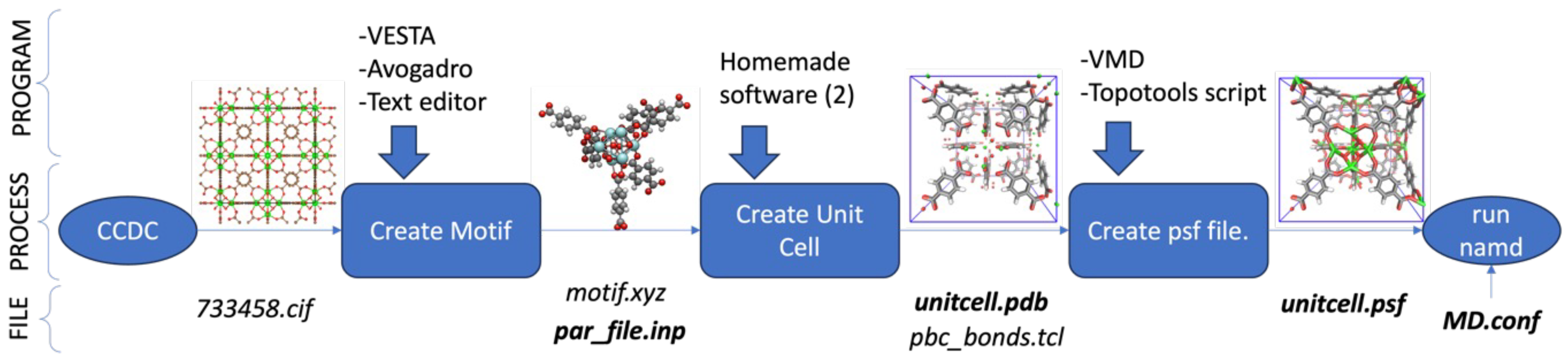
Figure 6.
(orthographic view) A MOF fragment with atoms type corresponding to the structural parameters in Table 1.
Figure 6.
(orthographic view) A MOF fragment with atoms type corresponding to the structural parameters in Table 1.
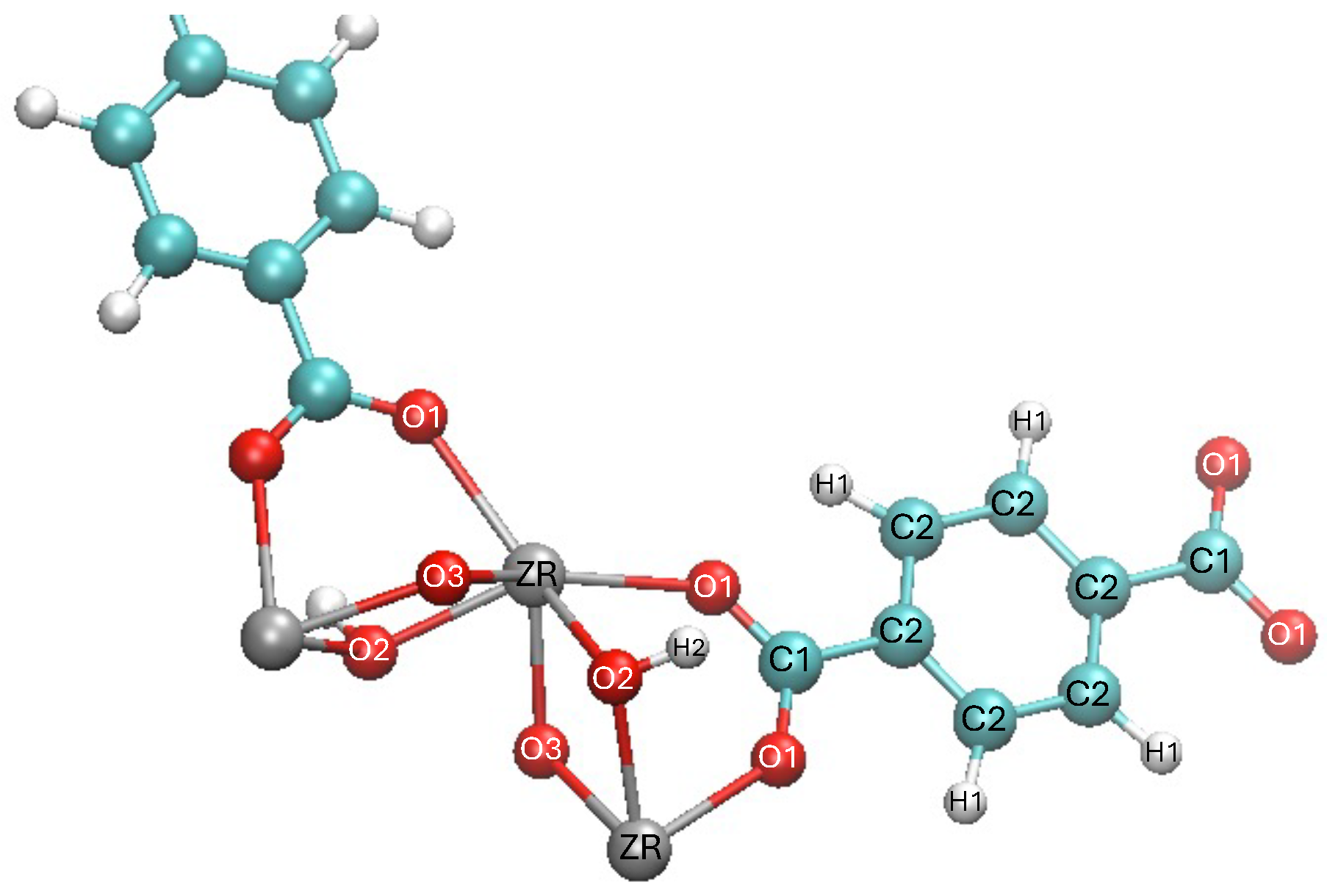
Figure 7.
(orthographic view) (a) Initial semi-periodic system, with surface S1 is analyzed. (b) Final structure corresponding to parameters of Table 2. (c) Final structure corresponding to parameters of Table 3. (d) Final structure corresponding to increase the constant force of the dihedral O1-C1-C2-C2 10 times.
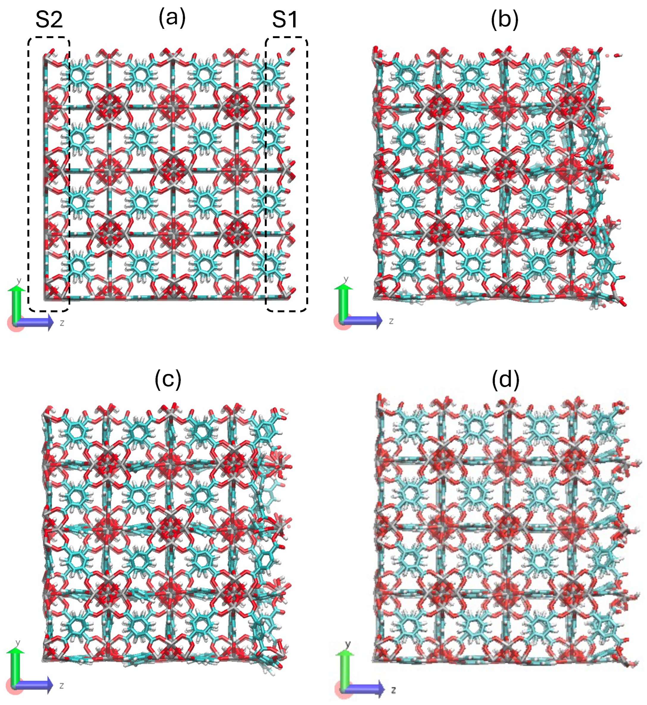
Figure 8.
(a) Motif for UiO-66-, nitrogen in blue; (b) 2x2x2 unit cell generate for the UiO-66-.
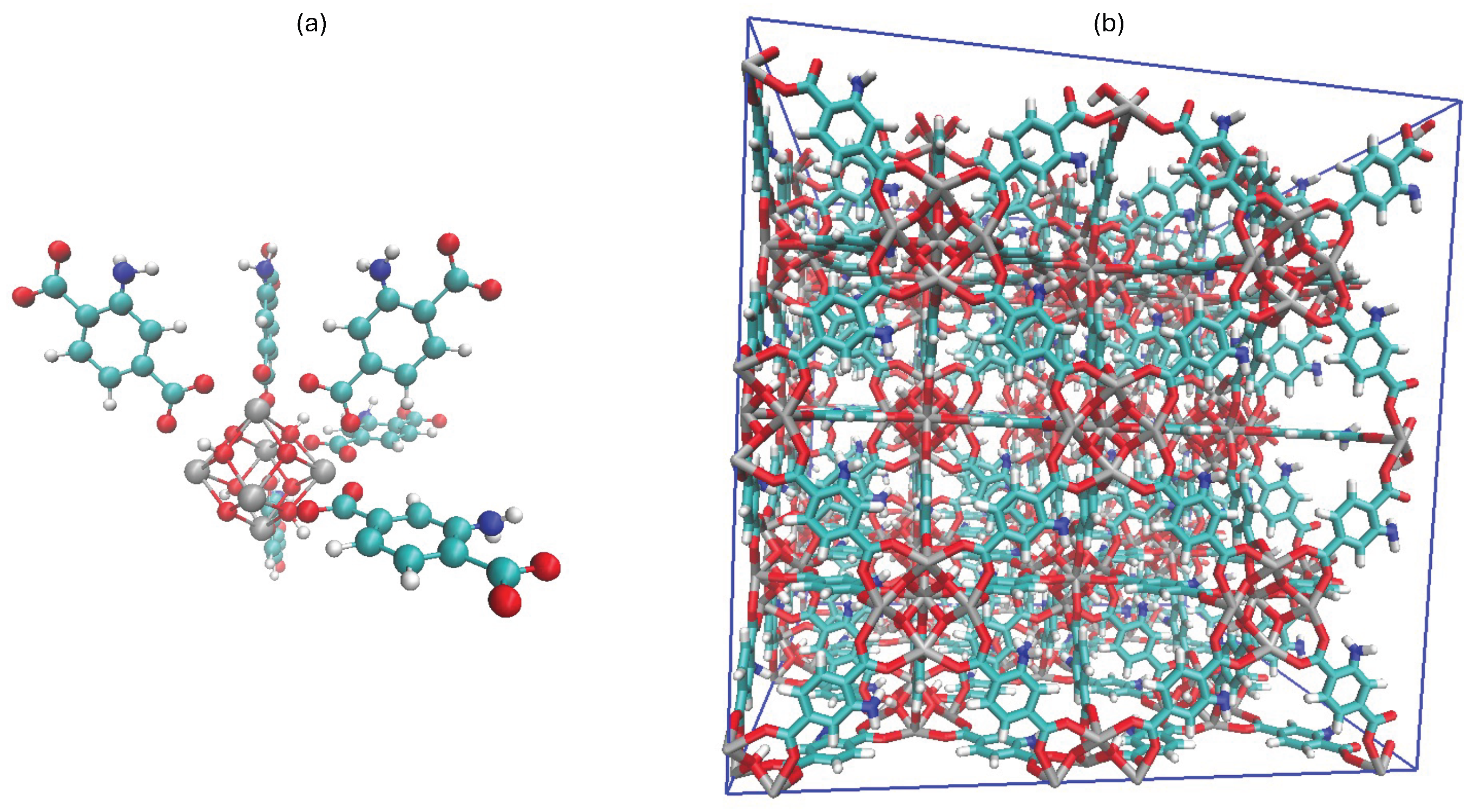
Table 1.
Structural results of the UiO-66. Full-periodic system.
| 100 K, 1 atm | 350 K, 1 atm | |||||
|---|---|---|---|---|---|---|
| Mean | Min | Max | Mean | Min | Max | |
| Bond ZR-O1 (Å) | 2.253 | 2.219 | 2.296 | 2.253 | 2.173 | 2.320 |
| Angle O1-ZR-O1 (degree) | 65.96 | 62.90 | 70.21 | 66.09 | 60.07 | 71.69 |
| Dihedral ZR-O1-C1-C2 (degree) | 176.12 | 168.98 | 179.99 | 174.30 | 160.55 | 179.94 |
Disclaimer/Publisher’s Note: The statements, opinions and data contained in all publications are solely those of the individual author(s) and contributor(s) and not of MDPI and/or the editor(s). MDPI and/or the editor(s) disclaim responsibility for any injury to people or property resulting from any ideas, methods, instructions or products referred to in the content. |
© 2025 by the authors. Licensee MDPI, Basel, Switzerland. This article is an open access article distributed under the terms and conditions of the Creative Commons Attribution (CC BY) license (http://creativecommons.org/licenses/by/4.0/).
Copyright: This open access article is published under a Creative Commons CC BY 4.0 license, which permit the free download, distribution, and reuse, provided that the author and preprint are cited in any reuse.


