Submitted:
14 May 2025
Posted:
15 May 2025
You are already at the latest version
Abstract
The rapid evolution of military technology has led to an increased interest in Unmanned Combat Aerial Vehicles (UCAVs). This research focuses on the conceptual design of a low-cost, turbofan-powered UCAV, specifically a Class-III aircraft as defined by NATO classification (STANAG 4670), with a target take-off weight of approximately one tonne. The study adopts a "from scratch" design approach, recognizing the limitations of existing data and the potential for scaling errors. This approach involves a meticulous design process that includes the development of precise requirements, weight estimations, and iterative optimization of the aircraft layout to ensure aerodynamic efficiency and operational functionality. A key element of this conceptual design is its focus on a low-cost profile, achieved through the adoption of a simplified structural layout, and the integration of off-the-shelf components where possible. The design process involves an iterative approach, beginning with fundamental requirements and progressing through the detailed development of individual components and their integration into a cohesive aircraft. The study details the selection of an existing and operational engine due to its power output. The design and analysis of the wing, fuselage, and V-tail configuration are presented, incorporating considerations for aerodynamic efficiency, stability, weight estimation, and internal component layout. The study concludes by outlining recommendations for future work, including high-fidelity CFD simulations, structural analysis, and the integration of advanced electronic systems and AI capabilities essential for the Loyal Wingman concept.
Keywords:
UCAV
; loyal wingman
; class-III UAV
; conceptual design
1. Introduction
1.1. Overview
The rapid evolution of military technology has spurred interest in Unmanned Combat Aerial Vehicles (UCAVs), which offer enhanced mission capabilities, reduced risk to human pilots, and greater operational flexibility. The "Loyal Wingman" concept, where UCAVs collaborate autonomously with manned aircraft, represents a key advancement in modern warfare, extending the reach of manned platforms in roles such as intelligence, surveillance, reconnaissance, electronic warfare, and offensive combat operations. Acting as force multipliers, these UCAVs provide operational versatility while mitigating risks to human pilots.
At the moment, Loyal Wingman UCAVs face design challenges due to the scarcity of verified empirical data and the infancy of the concept. Limited or inconsistent information makes accurate performance modeling and weight estimation difficult, particularly when scaling existing designs to larger, more complex UCAVs. To address this, the research adopts a "from scratch" design approach, focusing on a Class-III (NATO Classification, STANAG 4670 [1]) turbofan-based UCAV with a target takeoff weight of approximately one tonne, lighter than any existing developmental UCAV up to date. Existing UCAV designs are compared in terms of their performance characteristics and payload capacity, as a foundation to extract the requirements for this design. This approach ensures an optimized and cost-effective design tailored to specific operational requirements, avoiding the pitfalls of scaling existing profiles. The study emphasizes affordability through simplified structural layouts, reliance on commonly-used manufacturing methods, and the integration of off-the-shelf components where possible, such as a standardized turbofan engine and materials.
It is based on the master’s thesis titled “Conceptual Design of a Turbofan-Based Loyal Wingman UAV: Towards a Class-III Aircraft“ by the contributing author Roussos [2], supervised by professors Lappas, Kostopoulos and co-supervised by PhD candidate Karatzas, and focuses on the design of the wing, tail, and internal layout and spatial planning for optimal weight distribution and center of gravity management. In-depth analyses of structural integrity, AI systems, flight controls, sensors, and detailed payload integration fall beyond the scope of this first study.
1.2. State Of The Art
The late 20th century saw breakthroughs in autonomous aircraft. Modern UAVs exemplify a convergence of advanced technologies, expanding their capabilities across military and civilian domains. Notable platforms like the RQ-2 "Pioneer" and MQ-1 "Predator" showcased UAVs’ dual utility for surveillance and combat operations. The emergence of smaller, tactical UAVs such as the RQ-11 "Raven" and Black Hornet Nano reflected a growing demand for portable, easily deployable systems for ground forces. The integration of Artificial Intelligence (AI) further enhanced UAV autonomy, decision-making, and mission flexibility.
Today’s UAVs perform a wide range of functions, from intelligence gathering and combat to logistical support. Class III UAVs, with their larger payload capacities and extended endurance, are particularly suited for the role of a Loyal Wingman. The "Tísis" UCAV exemplifies this concept, as a one-tonne, turbofan-powered Class III platform (NATO Classification) designed to collaborate with manned systems. Its design could reflect cutting-edge advancements and aim to demonstrate the feasibility of future unmanned combat systems. The historical trajectory and state-of-the-art developments in UAVs illustrate a dynamic field shaped by technological innovation and evolving mission requirements.
1.3. Existing UCAV Comparative Analysis
This section aims to identify the key requirements for the conceptual design of a Loyal Wingman UCAV by analyzing trends observed in existing and developmental jet-powered Class-III UCAVs (Table 1). The analysis evaluates performance parameters to establish clear design criteria essential for shaping the foundational parameters of a 1-tonne UCAV, ensuring it aligns with the characteristics of a Loyal Wingman while remaining competitive and operationally viable in real-world scenarios.
Most existing UCAVs fit the profile of intelligence, surveillance, reconnaissance (ISR), and precision strike platforms due to their design characteristics and operational roles. Models like the S-70 Okhotnik-B and nEUROn prioritize stealth, endurance, and long-range capabilities over agility and maneuverability, making them less aligned with the traditional "dogfighter" profile, which demands high agility and exceptional maneuverability. Among current designs, the Kizilelma-A stands out with its emphasis on high-speed, maneuverability, and a larger payload capacity, suggesting potential for closer engagement profiles. However, the UCAV designed in this thesis will follow multi-role "Loyal Wingman" trends, incorporating agility and versatility without focusing specifically on dogfighting.

Table 1.
Specifications of existing developmental UCAV models.
| Model | Configuration | MTOW [lb] | Empty Weight [lb] | Max. Speed [kts] | Payload [lb] | Percentage of MTOW | Length-to-wingspan Ratio |
|---|---|---|---|---|---|---|---|
| Anka-III [3] | Flying Wing | 14330 | - | 425-450 | 1653 | 11.5% | 1.22 |
| CATS Warrior [4] | Conventional | 4630 | - | Mach 0.9 | - | - | |
| Kizilelma-A [5] | Canard | 13200 | - | 590 | 3300 | 25% | 1.51 |
| MQ-28 Ghost Bat [6,7,8] | Conventional | - | - | 600 | - | - | 1.60 |
| nEUROn [9] | Flying Wing | 15432 | 10803 | 529 | 1014 | 6.6% | 0.76 |
| S-70 Okhotnik-B [10,11,12] | Flying Wing | 55116 | - | 540 | 4410-6172* | 8.0-11.2% | 0.79 |
| X-45A [13,14] | Hybrid | - | 8000 | 533 | - | - | 0.78 |
| XQ-58 Valkyrie [16,17,18] | Conventional | 6000 | 2500 | 566 | 1200 | 20% | 1.20 |
* Not Confirmed.
1.4. Design Uniqueness and Novelty
The novelty of this UCAV design resides mainly in the concept itself. Potentially establishing a new weight category with a Maximum Takeoff Weight (MTOW) of 1000 kg—-approximately half that of the lightest current developmental model (e.g., HAL CATS Warrior, maiden flight planned for 2025)– this lightweight configuration, combined with high-speed capability and a high percentage of MTOW allocated to payload, enables mission-specific flexibility through trade-offs between payload and fuel to extend range or boost speed, hence the importance of achieving a high percentage of MTOW utilized for payload as will be examined in the upcoming sections of this article. The compact size allows for operations from minimal runways or static rocket-assisted launches, while inherently contributing to a reduced radar cross-section. As the first UCAV conceived from scratch in Greece, tailored to cover the country’s operational range and collaborate with aircraft operated by the Hellenic Air Force, this design represents a significant step in lightweight Loyal Wingman development.
2. Methodology and Design Process
2.1. Conceptual Design Methodology
The design methodology followed for this design (Figure 1) is a farrago of well-established approaches for designing an aircraft, from designers such as I. Roskam, D. Raymer and M. Sadraey [19,20,21], whose methodologies have been thoroughly followed in this study. Roskam’s methods were utilized for initial and performance sizing, providing most empirical values for parameters such as L/D and SFC. Raymer’s work complemented Roskam’s, particularly regarding aspect ratio, SFC variation, and correlations between empty weight and MTOW for similar manned aircraft and UAVs. Sadraey contributed to the methodology for wing, tail, and fuselage design, static stability analysis, weight estimation of various components, and landing system design, especially the critical angles for ground stability. Finally, Kallinteris [22] provided additional empirical data and restrictions for these critical angles during landing system design, along with design considerations about HLD design and the estimation of available fuel space inside the wings.
2.2. Design Requirements
The mission requirements for the "Tísis" UCAV prioritize a balance between performance and feasibility, guided by benchmarks from operational UCAVs like the ones mentioned in Table 1. While larger platforms achieve greater ranges and speeds, the design constraints of a 1-tonne UCAV necessitate trade-offs in altitude, endurance, and propulsion. Key parameters–such as ambient conditions ( at sea level), takeoff/landing distances, high-speed–are tailored to align with Hellenic Air Force operational needs, though they remain ambitious given the platform’s smaller size. The flight profile (Figure 2) and detailed specifications (Table 2) reflect these calibrated goals. It should be noted that, although total endurance is not prioritized, a loitering capability of 20 minutes is specified to support mission adaptability.
2.3. Initial Sizing
2.3.1. Iterative Refinement of Weight Estimations
The initial sizing of the "Tísis" UCAV employs an iterative method to estimate empty weight, fuel requirements, and payload capacity. Due to the limited availability of data on Class-III UAVs, empirical data from manned subsonic and transonic military aircraft are used and adjusted to account for modern aerodynamic and propulsion advancements. Parameters such as specific fuel consumption () and maximum lift-to-drag ratio are obtained from literature and refined through aerodynamic simulations [20].
The iterative process starts with an assumed payload fraction of MTOW, from which empty and fuel weights are computed. Empty weight estimation follows a logarithmic correlation with MTOW, and fuel weight is determined using mission-specific performance models, notably the Breguet range equation for cruise and loiter. A reserve fuel margin of 5% MTOW and a trapped fuel allocation of 0.5% are included. The process converges once the calculated empty weight meets a predefined error threshold. Key design inputs include:
- A wing aspect ratio derived from statistical data for conventional configuration.
- Modified, thrust-specific fuel consumption values for a low-bypass ratio (LBR) turbofan engine without afterburner.
All parameters and fuel ratios f or each mission phase are summarized in Table 3.
2.3.2. Streamlined Methodology
To reduce design time and development costs, the methodology prioritizes pragmatic decisions over highly detailed conceptual estimation. Reference data from manned subsonic and transonic military jets forms the foundation for initial configuration definition. Raymer’s method [20], linking to wetted aspect ratio (), is selectively employed and refined using empirical corrections for improved aerodynamic fidelity. The sizing process is conducted for three MTOW values–900 kg, 1000 kg, and 1100 kg–to evaluate payload efficiency. As shown in Table 4, the 1100 kg case yields the most favorable payload-to-MTOW ratio and is therefore selected as the final design reference.
2.3.3. Challenges and Limitations
Designing a Loyal Wingman UCAV poses unique challenges, primarily due to the developmental nature of such systems and the scarcity of direct empirical data. While leveraging data from comparable manned aircraft accelerates early-stage design, it introduces uncertainties, particularly in fuel and weight estimations. These limitations are addressed through a sensitivity analysis that quantifies how variations in key assumptions—such as payload fraction, fuel consumption, and aerodynamic efficiency—affect MTOW. The findings, provided in Table 5, guide refinement priorities and ensure robustness in weight budgeting.
2.4. Configuration Selection and Rationale
A conventional configuration with a wing and aft tail was selected for the UCAV based on practical, operational, and developmental criteria, as well as reference to aircraft such as the XQ-58 Valkyrie and MQ-28 Ghost Bat. This layout is well-documented, supports predictable stability and control characteristics, and facilitates efficient design within the project’s limited 6–8 month timeframe [20]. The mission profile—emphasizing strafing and agile maneuvers in mid- to high-subsonic regimes—requires handling qualities best provided by conventional configurations.
Alternative layouts such as delta-wings or flying-wings were considered but dismissed. Delta wings, although structurally efficient and favorable for high-speed flight, suffer from poor low-speed handling and pitch stability issues. Flying-wing designs offer stealth and endurance advantages but lack agility and require advanced fly-by-wire systems for stability [23]. The selected configuration achieves a balanced compromise between maneuverability, simplicity, and cost-effectiveness, aligning with the design objectives for a reliable, low-cost Loyal Wingman UCAV.
2.5. Performance Sizing
This stage of the design process serves the purpose of determining the minimum reference area for the main lifting surfaces () of the aircraft and the minimum required thrust (T). The performance sizing is conducted based on the four following performance criteria:
- Takeoff Distance
- Landing Distance
- Flight Speed
- Climbing Performance
These criteria are based on regulations, such as FAR-23 for propeller airplanes, FAR-25 for jet-powered aircraft and MIL–3013A for military aircraft. Their application is performed according to the methodology by I. Roskam [19] and utilized in this study, from which all the equations and application methods presented below are taken.
The determination of the total drag coefficient () is a critical step in the conceptual design phase of the "Tísis" UCAV, since it directly influences the aircraft’s performance characteristics. comprises two primary components: zero-lift or parasitic drag () and induced drag (), for use in performance sizing calculations.
where k is the induced drag term, which is further defined as where is the wing aspect ratio, and e is Oswald’s efficiency coefficient. Empirical data from existing comparable aircraft were utilized to estimate . First, an indicative value for at 50 psf is chosen. This value may be subjected to reevaluation in later stages of the design process. Since the MTOW is known, this assumption yields a tentative wing reference area of 48.5 ft2. The relationship used to estimate the parasitic drag for the aircraft is presented in Equation (2) [20,22].
where is the wing reference area, the total wetted area of the UCAV and is a mean friction coefficient, which is assumed to be 0.0035 for fighter aircraft [20]. The total wetted surface can be tentatively estimated based on empirical data through the utilization of Equation (3).
where c,d equal –0.1289 and 0.7506, respectively [22]. The resulting wetted area is 258.03 ft2 yielding a parasitic drag coefficient of 0.01862 via Equation (2).
Increments to are applied for high-lift devices (HLD), landing gear, and compressibility effects during high-speed flight, as detailed in Table 6 and Table 7. External components (e.g., sensors, antennas) and interference drag (5%–10% of total drag) are acknowledged but not explicitly quantified. No additional is considered for interference drag due to the engine’s internal placement and proper design practices.
The wing aspect ratio (AR) is initially derived from D. Raymer’s method for canard-bearing aircraft, which accounts for the additional lift provided by canards and the conceptual sketch-based method mentioned in Subsection 2.3.2, adjusted by a factor of 0.9 to account for the absence of a canard on "Tísis" UCAV. The final AR of 5.0 is selected, with drag polars calculated and presented in Table 8. Maximum lift coefficients for take-off ) and landing () are tentatively set to 2.0 and 2.4, respectively, based on [19,22]. Air density values are obtained from Table A1.
2.5.1. Performance Criterion [1]: Takeoff Field Distance
The take-off field length () includes the ground run distance (), with a requirement of . The relationship between thrust-to-weight ratio (T/W) and weight-to-wing reference area ratio (W/) is given by the empirical formula in Equation (4).
where is air density, is the assumed bypass ratio for an LBR turbofan engine and is the friction coefficient for a dry tarmac runway [21,34]. The relationship between (T/W) and according to this criterion is the following:
2.5.2. Performance Criterion [2]: Landing Field Distance
The landing distance criterion follows military specifications (MIL-STD-3013A), similar to FAR-25 regulations, ith the key difference being that the approach speed for military aircraft is generally a smaller proportion of their stall speed than that of commercial airplanes. A maximum landing distance of 1000 ft is required initially (Table 2). A conservative approach is applied, assuming:
- No payload is discarded.
- Fuel consumption is less than the total mission requirement.
- No thrust degradation occurs (takeoff and landing altitudes match).
- The UCAV is assumed to weigh 85% of its MTOW during approach to account for this conservative scenario.
The landing field distance criterion is based on approximations of the approach speed () and the stall speed in landing configuration ():
This relationship between and is dictated by military standards. By translating from knots to fps and considering the assumed maximum lift coefficient in landing configuration of 2.4, the criterion yields the following relationship:
2.5.3. Performance Criterion [3]: Flight Speed
The analysis targets two key high-speed flight conditions: cruise and dash. For steady, level flight, the equations governing thrust (T) and lift (L) are given by:
D being the aerodynamic drag, W the aircraft’s weight, V the flight speed and the air density at flight altitude. By combining the last two equations and substituting Equation (1) where needed, the thrust-to-weight ratio () can be expressed as a function of wing loading ():
where is the dynamic pressure and i denotes the flight phase (e.g., cruise-out or dash-out).
Cruise-Out Phase
The UCAV is designed to maintain a cruise speed of Mach 0.80 at an altitude of 30000 ft. For this phase:
- The maximum cruise speed is assumed to be 1.2 times the specified cruise speed, resulting in knots due to the fact that cruise speeds for jet aircraft are usually calculated at 75–80% thrust [21].
- The corresponding dynamic pressure is calculated as psf.
- A conservative weight assumption is applied, using the maximum weight at the start of the cruise-out phase.
- A thrust lapse ratio adjusts the thrust-to-weight ratio for altitude-induced thrust degradation [21]:
The relationship between and adjusted to take-off weight and the altitude-induced thrust degradation at cruising altitude is the following:
Dash-Out Phase
The UCAV is required to reach a dash speed of Mach 0.90 at 5000 ft. For this phase:
- The dynamic pressure is calculated as psf.
- A conservative weight assumption is applied at the beginning of the dash-out phase.
- Thrust degradation is again considered using Equation (12).
Again, the relationship between and adjusted to take-off weight and the altitude-induced thrust degradation at dashing altitude is the following:
2.5.4. Performance Criterion [4]: Rate of Climb (ROC)
The UCAV must meet specific ROC requirements as defined by military standards. These requirements are critical for ensuring the aircraft can achieve and sustain desired altitudes under various operational conditions [19]. Key altitude thresholds include:
- Absolute ceiling: The maximum altitude where the ROC reduces to zero.
- Service ceiling: The altitude where a ROC of 100 ft/min can be sustained.
- Cruise ceiling: The altitude where a ROC of 300 ft/min is maintained, typical for subsonic fighters.
- Combat ceiling: The altitude where a minimum ROC of 500 ft/min is achieved.
A linear relationship between ROC and altitude is assumed. Whether this relationship is linear in reality depends on the engine, the characteristics of the airplane, and the flight speed at which the climb is performed. Be that as it may, this assumption can be made and provide adequate results for the initial sizing [19].
The thrust-to-weight ratio (T/W) for ROC performance is derived from:
The lift-to-drag ratio is maximized for the optimum ROC and is calculated using the following formula:
ROC – Cruising Altitude
At the cruise altitude of 30000 ft, the UCAV must maintain a minimum ROC of 300 ft/min, as stipulated by military standards [19,34]. Thrust is adjusted for altitude-induced degradation using , and the weight is set to , representing the mean cruise-out weight. Using aerodynamic data from Table 8 and air density values from Table A1, the relationship between and is:
ROC – Sea Level
Unlike the climb rate at cruise ceiling, which is specifically required, the sea level climb rate needs to be determined based on assumptions regarding the UCAV’s performance. The sea level ROC is determined based on a linear ROC-altitude relationship, which is a reasonable assumption for initial sizing [19]. The UCAV is required to reach the cruise altitude of 30000 ft in 10 minutes (). An absolute ceiling () is assumed. The ROC at a given altitude h and at sea level can be obtained from the following equations:
Fighter jets typically have steeper flight path angles during climb (). For steep flight path angles the following applies:
The design is based on the extreme scenarios; therefore, it will be assumed that the ROC is maximized, which requires maximizing the lift-to-drag ratio. Another assumption is made; at the beginning of the climb phase the aircraft is in take-off configuration with retracted landing gear. By applying the methods of Roskam, [19], the relationship between and is the following:
2.5.5. Prevailing Performance Criterion
Each of the aforementioned criteria defines a constraint on the – relationship, visualized in performance sizing graphs. These constraints, derived from Equations (5), (8), (13), (14), (17), and (21), create permissible design regions. The intersection of these regions defines the feasible design space, with the optimal solution expected along the boundary where the most restrictive constraints meet.
Initially, the landing field distance criterion determines the wing reference area (), while the dash speed criterion governs the minimum required thrust. After updating , the parasitic drag coefficient (Equation (2)) is recalculated, shifting the governing constraint to the sea-level ROC criterion for thrust. The final values are 1483.95 lbf for thrust and 68.04 ft2 minimum wing reference area, as shown in Figure 3 and Table 9, respectively.
2.6. Engine Selection
The engine selection process evaluated multiple low-bypass ratio (LBR) turbofan models to meet the UCAV’s mission requirements. The minimum required thrust is 1490 lbf, with engine dimensions, weight, and specific fuel consumption (SFC) as critical factors. Among six candidates (Table 10), the Williams FJ33-5A was selected due to its higher power output, adaptability for future upgrades, and comprehensive performance data. However, compatibility at high speeds (Mach 0.90 during dash) requires further verification. Despite this, the FJ33-5A’s performance and data availability made it the optimal choice.
3. Wing Design
The UCAV’s wing design is optimized for cruise-out efficiency, as this phase provides a consistent performance benchmark unaffected by payload jettison variability. Aerodynamic efficiency is achieved by minimizing drag while generating the ideal lift coefficient with acceptable moment characteristics. The average cruise-out mass, calculated from fuel fractions in Table 3, is:
The ideal lift coefficient, derived from this mass and flight conditions, is adjusted by wing (0.95) and airfoil (0.855) correction factors to account for lift contributions from the fuselage, tail, and other components [21]. Similarly, the maximum lift coefficient at MTOW and sea level is computed and adjusted, with plain flaps tentatively selected as high-lift devices for their cost-effectiveness. The resulting key coefficients (Table 11) guide the wing design process: the ideal lift coefficient () ensures cruise efficiency, while the maximum () serves as a threshold for airfoil screening. Performance graphs and literature recommendations further refine the selection.
3.1. Airfoil Selection
The airfoil selection process evaluated twenty candidate airfoils (all airfoil data were derived from [30,31]) based on their ability to meet the maximum required lift coefficient () and their behavior at the ideal cruise lift coefficient. XFLR5 simulations (Figure 4) provided critical aerodynamic data, including drag coefficients (), lift-to-drag ratios (), and stall characteristics.
Initial screening rejected five airfoils for failing to meet the requirement. The remaining candidates were ranked by their drag coefficients at cruise conditions, with the seven highest-drag airfoils eliminated. A subsequent dash-phase analysis narrowed the pool to six candidates (Table 12). These were evaluated against four criteria:
- Control: Moment coefficients () near zero for agility and negative for stability.
- Stall: High stall angles to minimize stall speed.
- Speed: Low for high-speed performance.
- Endurance: High for efficient cruise.
Three airfoils were rejected during this phase: NACA 1410 due to excessive (0.00505), NASA for poor cruise efficiency with lowest (116.73) and abrupt stall at 16 during the approach phase, and NACA 63-412 with lack of standout performance. The final candidates—NACA 65-410, NACA 63(2)A-015, and NACA 65(2)-415—underwent further testing in OpenVSP Software. NACA 65-410 offered balanced performance with a high stall angle, while NACA 63(2)A-015 featured favorable moment coefficients for high-speed control. NACA 65(2)-415 emerged as the most aerodynamically efficient, with the lowest and highest .
For OpenVSP testing using the VSP-Aero package, the airfoils became wings, all configured with a 37.3 leading-edge sweep (per [21]), a taper ratio of 0.25, and thickness-to-chord ratios of 0.11 (root) and 0.10 (tip). VSP-AERO uses a vortex-lattice or panel solver aerodynamics method, which does not take into account boundary layer effects. Simulations employed the panel method (17 sections, 64 wake nodes) to capture thickness effects, with vortex lattice method (VLM) used after control-surface integration due to software constraints.
Final candidates tested in OpenVSP/VSP-Aero:
- NACA 65-410: High stall angle and acceptable .
- NACA 63(2)A-015: Despite having the highest of the remaining, it featured a favorable moment coefficient () for stability, but agility.
- NACA 65(2)-415: Optimal aerodynamic efficiency, with the lowest and highest .
– Dash & Cruise Condition Testing
Initial dash testing in OpenVSP evaluated three wing candidates (NACA 65-410, 65(2)-415, and 63(2)A-015) for local sonic flow at Mach 0.90. Simulations at four angles of attack (aoa), corresponding to four conditions for each wing - (0.07838), , , and an intermediate value - confirmed subsonic flow locally since the local velocity remained below the threshold of 1.111 or 1/0.9 (Figure 5). Subsequent analysis determined wing-specific aoas for achieving the ideal lift coefficient at dash () and cruise () (Table 13). These aoas, along with , were used for aerodynamic comparisons, both in dash and in cruise conditions, in two analyses with identical methodology.
NACA 63(2)A-015 emerged as optimal, exhibiting:
- Near-zero negative moment coefficient for stability and maneuverability.
- Lowest aoa for ideal lift and minimal induced drag at aoa
- Superior inverted flight capability due to the lowest induced drag and lift coefficient at 0, despite slightly higher induced drag than NACA 65-410.
It falls second to NACA 65-410 regarding the induced drag coefficient at , however NACA 65-410 exhibits the worst moment coefficient, thus not being the prevailing candidate airfoil.
3.2. Sweep, Taper and Thickness
Wing geometry optimization focused on preventing local sonic flow at Mach 0.90 while balancing aerodynamic/structural needs, particularly during dash phases where the aircraft flies at Mach 0.90 at 5000 ft. The analysis considers a range of angles of attack, from -5 ° to 20°, to assess performance across different flight conditions. The study evaluated:
- Taper ratios (): [0.20, 0.35, 0.60, 0.80]
- Sweep angles (): [35, 37.3]
OpenVSP simulations employed the Karman-Tsien compressibility correction [35], with lift distribution analyzed via normalized sectional coefficients (). While more complex methods like the Prandtl-Glauert transformation [36] are typically used for 3D flows for moderate compressibility effects (still not valid in full transonic regimes), the Karman-Tsien correction provided sufficient accuracy for this analysis considering the available resources. Key findings:
- Taper ratios 0.60/0.80 rejected due to positive moment coefficients (instability).
- showed superior stall characteristics vs.
- 37.3 sweep marginally outperformed 35 with no sonic flow observed (Figure 5).
Lift distribution across the wingspan was analyzed using the sectional lift coefficient (), normalized by the local chord length (c) and mean geometric chord () as . This metric correlates with load distribution, balancing the following objectives:
- Structurally, load should concentrate near the wing root to minimize bending moments.
Even if the lift distribution itself is not perfectly elliptical, the combination of local lift and the local chord c can still yield an elliptical distribution if the wing’s geometric parameters, such as taper ratio and sweep angle, are appropriately configured. Figure 7 and Figure 8 present the results of the simulations.
In Figure 8, the three upper graphs present the sectional load distribution across the wing span, and the three lower graphs the sectional lift distribution. While the load distribution approaches the elliptical (desirable), it is obvious that the lift distribution deviates from it, more for some wing configurations than others. To validate the simulation results, theoretical methods including Lifting Line Theory (LLT) [21] were employed. While LLT provides reliable lift estimation within operational ranges (excluding stall effects), significant discrepancies emerged when compared to OpenVSP outputs.
These differences stem from LLT’s linear assumptions failing to capture compressible flow effects at Mach 0.90, combined with potential limitations in VSP-Aero’s drag prediction models [37]. Specifically, while LLT suggested a taper ratio of 0.22 would minimize induced drag ([2]), OpenVSP simulations consistently demonstrated superior performance with 0.35 taper ratio, exhibiting more favorable moment coefficients, higher stalling angles of attack, and marginally lower induced drag (Figure 9).
Given these inconsistencies and to maintain methodological consistency, the wing parameters were finalized based on OpenVSP results. This approach aligned with the design process methodology where airfoil and wing parameters were predominantly determined using computational tools (OpenVSP and XFLR5) as the primary reference. Further investigation and possibly the use of more sophisticated CFD tools may be required to reconcile these differences and achieve a more accurate assessment of induced drag for different taper ratios.
3.3. Wing Twist and Setting Angle
Wing twist is crucial for controlling the stall characteristics of the wing, ensuring that the wing root stalls before the tip. This is important because if the root stalls first, the ailerons, located near the wingtip, remain effective, allowing the pilot to maintain control of the aircraft during a stall. Simulations are run to determine whether it would be significantly beneficial for wing twist to be implemented to the design. Avoiding this modification would result in simpler manufacturing of the wing with lower cost.
To evaluate the impact of wingtip twist on aerodynamic performance during cruise, two configurations were tested: one with tip twist and another with . Figure 10 compares the aerodynamic coefficients for both cases, revealing negligible differences, slightly favoring the twist configuration. However, these differences are too minor to justify the added cost and complexity associated with manufacturing a twisted wingtip. Furthermore, Figure 11 illustrates the sectional wing loading factor and lift distribution at stall initiation, showing that stall does not originate at the wingtip. Since one of the primary purposes of tip twist is to mitigate tip-stall, its implementation is unnecessary in this design.
To further minimize the spread of stall across the wingspan, potential aerodynamic measures like wing fences could be explored. However, such interventions require detailed aerodynamic analysis and fall beyond the scope of this thesis. The wing setting angle, which ensures the optimal lift coefficient () during cruise, is determined through linear interpolation of the data in Figure 10 and given below:
3.4. High-lift Devices (HLD)
To increase lift at lower speeds, the design initially uses plain trailing-edge flaps due to their simplicity and low cost. However, calculations based on [21,22] showed that even a 55° deflection angle–the typical limit for ensured structural integrity [22]– was insufficient for landing. To address this shortfall, the design process explored a compromise between achieving the required lift characteristics and adjusting the landing distance, since the landing distance criterion determines the wing area and is directly compromised by reducing the maximum lift coefficient () for landing without a complete wing redesign or adjustments to the required landing distance. Iterative analysis balanced these factors, allowing the adoption of a single-slotted flap configuration instead of more complex alternatives like Fowler flaps or leading-edge HLDs. This configuration offered an optimal trade-off between aerodynamic performance, structural simplicity, and cost.
The maximum lift coefficient’s final value at landing is revised at 1.80, which suggests an increase of 33.35% for the total landing distance to 1333.35 feet. This pair of values allows for the wing reference surface to remain unchanged with a toll of 333.35 extra feet or 101.61 meters for the landing distance. For takeoff, was reduced to 1.50, lowering flap deflection and drag. Table 14 summarizes the finalized flap parameters, while Figure 12 depicts the top view, showing flaps, ailerons, and the aircraft’s aerodynamic center (), typically at 20-30% MAC [21].
3.5. Wing Weight
3.5.1. Wing Structure
The wing weight was estimated based on the methods presented by M. Sadraey [21] that account for gravity, material density, and load factors. The wing was designed with a maximum load factor of 6.5 (yields an ultimate design load factor of 9.75 based on typical values mainly for training fighter aircraft). A material density of 5.45 slugs/ft3 was determined based on an assumed composition of 55% aluminium, 35% CFRP, and 10% steel. The resulting wing constitutes 6% of the MTOW and that is for the wing structure only. Fuel, actuators, fuel tanks and systems are not included.
3.5.2. Fuel Capacity
The wing fuel capacity () of the "Tísis" UCAV, in ft3, was estimated using the empirical formula from [22]:
where is the wing reference area (ft2), b the wingspan (ft), the thickness-to-chord ratio, the taper ratio, and the ratio . The formula accounts for fuel storage up to approximately 85% of the span to avoid fuel near the tips, reducing fire risk from lightning strikes. Initially, values of 0.11 (root) and 0.10 (tip) left a 70-liter shortfall. To correct this, the ratios were adjusted to 0.12 (root) and 0.11 (tip). VSP-Aero simulations confirmed the absence of sonic flow during critical phases (dash and cruise) with these refined values [2]. Using these updated parameters in Equation (25), the wing accommodated 0.3657 m3 (12.92 ft3) of fuel, still 40 liters short of the required 0.4049 m3 (14.30 ft3, assuming a fuel density of 807.5 kg/m3 [21]). The shortfall was covered by two small fuselage trim tanks. External tanks were avoided to preserve aerodynamic performance and minimize radar cross-section. Wing parameters are summarized in Table 14.
Now that all parameters are calculated, the wing’s mean aerodynamic chord can be determined (Equation (27)) and the Oswald’s coefficient e can be refined according to the following formula for swept wings [21]:
The refined value for e is used to reassess the required thrust at 1457.58 lbf (previous value: 1483.95 lbf). Additionally, it is observed that the difference between MGC and MAC is 0.285 ft or 8 cm, a very small proportional difference which is enough to justify the use of the mean geometric chord for calculations until all parameters are determined and MAC can be calculated accurately.
4. Fuselage Design
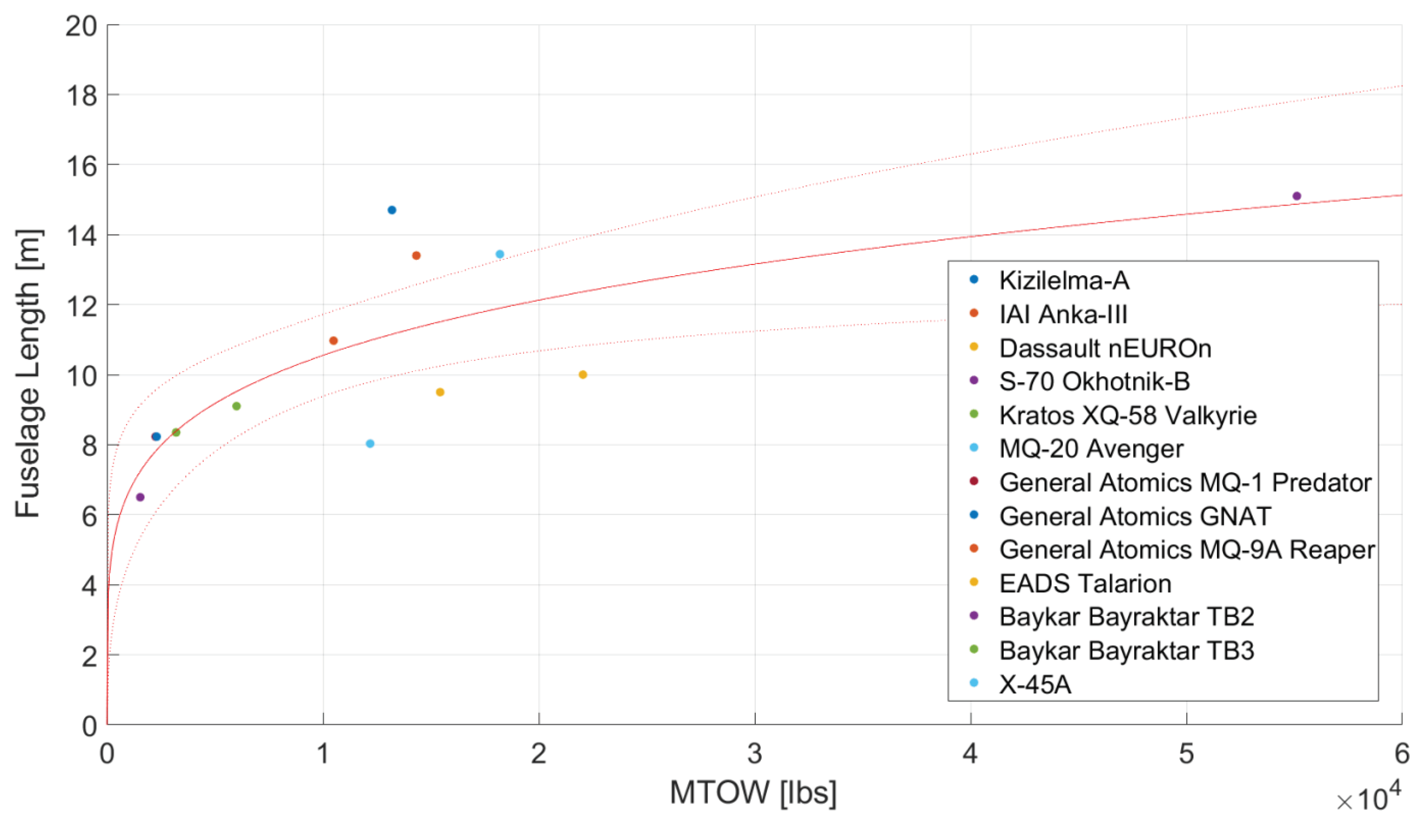
The fuselage design of the "Tísis" UCAV is designed to prioritize an efficient internal layout and stability during flight. Initial length estimates of 26.0 feet, based on statistical data from Class-III UAVs and UCAVs (Figure A1) were refined to 22.5 feet after considering stability, tail effectiveness, and wetted-area reduction.
Figure 13.
Fuselage cross section at the tail attachment - Geometry editor in OpenVSP Software
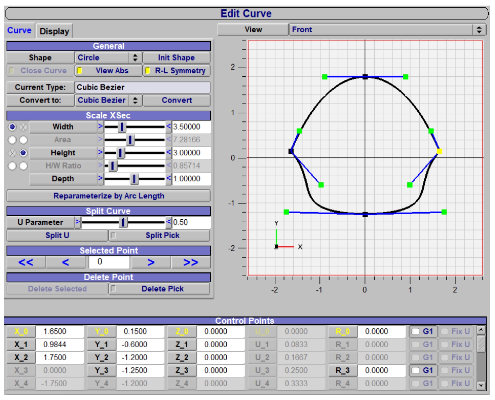
The fuselage is divided into two sections: the front houses electronics, sensors, radar, and front landing gear, while the rear contains the engine, exhaust, stabilizers, and rear landing gear. The payload bay is integrated with wing and landing gear placement (Figure 14–blue box). The engine duct, positioned on the upper fuselage, enhances protection from ground fire and debris while utilizing the fuselage and wing for radar shadowing. The rear section features a bell-curve cross-section, tapering from 3.50 ft (horizontal) and 3.00 ft (vertical) at the engine inlet to 3.30 ft and 2.20 ft at the tail attachment point, forming a cone-like shape linked to the tail design (Section 5). The fuselage diameter was determined by balancing flap span, internal volume, and drag minimization. With the Williams FJ33-5A turbofan’s diameter of 24.75 inches (Table 10) setting the minimum requirement, the horizontal dimension was finalized at 3.50 feet to optimize aerodynamic efficiency and internal space. Two chined edges, inspired by designs like the XQ-58 Valkyrie and MQ-28 Ghost Bat, enhance aerodynamics and reduce radar cross-section. The engine is mounted rearward and slightly upward, creating space for rear landing gear and fuel tanks. An S-duct intake and exhaust configuration is assumed to maintain thrust efficiency while providing protection.
4.1. Fuselage Weight
The weight of the fuselage is estimated using the empirical formula in Equation (28). The fuselage is assumed to be constructed primarily of aluminum (52%), with additional kevlar components kevlar and other protective materials (8%), CFRP (30%), and steel (10%). This material combination yields a fuselage density of 2766.22 kg/m3. The fuselage density factor (), which accounts for variations in fuselage design and internal components, is chosen as 0.00235 based on typical values for UAVs [21]. An engine inlet parameter () of 1.25 is applied since the fuselage incorporates engine inlets. The ultimate load factor is the same as the one assumed in Subsection 3.5.1 and the equivalent diameter () is 3.171 ft. The calculated weight represents 8.36% of the UCAV’s MTOW.
5. Tail Design
5.1. Configuration and Initial Considerations
The initial design phase for the tail of the “Tísis” UCAV focuses on creating a conventional aft tail configuration. The goal is to establish a solid foundation for stability and control following the approach recommended by M. Sadraey [21], allowed for a systematic determination of key parameters, including the tail volume coefficients ( and ), planform areas, aspect ratios, airfoil selections, and incidence angles, all while considering the influence of factors such as wing downwash and fuselage shape. The design process emphasizes optimizing the tail for cruise conditions.
Aircraft like the “Tísis” UCAV are designed to be stable during flight but approach neutral stability to enhance maneuverability and agility. This ensures smaller control inputs result in quicker responses and also why most modern aircraft are very difficult to handle without fly-by-wire systems. Longitudinal stability requires the aerodynamic center () or neutral point to be located behind the center of gravity (cg) [22]. If the neutral point is ahead of the cg, disturbances can cause destabilizing moments, such as an uncontrollable pitch-up [21]. There are ways to move the center of gravity forward, by arranging the internal components differently. For now, the aircraft’s center of gravity is tentatively assumed to be at 55% of the fuselage length, across the longitudinal axis of the aircraft and placed 10 cm behind the aircraft’s neutral point. This arrangement ensures sufficient space for the tail, as the remaining fuselage length from the to the aft tip (10.13 ft) exceeds the optimal tail arm length () calculated in Equation (29).
5.2. Horizontal Tail
5.2.1. Tail Parameters
The tail design follows established conceptual design methodologies [21], prioritizing maneuverability and stability trade-offs typical of fighter aircraft. Key parameters are derived as follows:
- Tail Moment Arm: The optimal arm () is calculated (Eq. 29) to minimize drag while ensuring tail effectiveness, yielding 7.86 ft. A correction factor () accounts for fuselage end-shape effects and symbolizes the fuselage’s equivalent diameter.
- Tail Area: The horizontal tail area () is determined via the tail volume coefficient (), resulting in 12.78 ft2:
- Pitching Moment: The wing/fuselage pitching moment coefficient () is calculated (Eq. 31) using airfoil data from NACA 63(2)A-015 (wing) at cruise , yielding :
- Aerodynamic Center: The wing/fuselage aerodynamic center () is tentatively placed at 23% MAC (Fig. Figure 12), pending CFD validation in later studies.
Design Rationale:
- The value reflects fighter-like longitudinal instability for enhanced controllability.
- The ratio (0.35) slightly exceeds the typical 0.30 for aft-tailed designs due to engine integration constraints.
Aerodynamic Considerations:
- The tail is designed for cruise but sized to ensure low-speed stability (turning rates have not yet been taken under consideration).
- The process of airfoil selection is by now familiar to the reader being the same as the one followed in in Subsection 3.1. Symmetric airfoil NACA 63A-010 is selected for its consistent performance at positive/negative angles of attack–long lift-curve slope ().
- The tail setting angle () accounts for downwash effects from the wing to the tail.
Stability: The static longitudinal stability derivative () is negative, confirming a stable design [21].
5.3. Vertical Tail
The process for designing the vertical stabilizer matches the one followed for the horizontal tail. The main objective of this design is to determine crucial parameters for the vertical stabilizer–its span, planform area and aspect ratio–to serve as an imaginary surface used as the V-tail’s projection on the vertical axis. This approach is explained and depicted in Subsection 5.4. The aforementioned parameters are incorporated in the finalized V-Tail configuration.
5.4. V-Tail Adjustment
The designed conventional tail serves as the basis for the transformation into the final V-tail configuration, which replaces the traditional horizontal and vertical stabilizers with two angled surfaces and offers potential advantages for the "Tísis" UCAV. By reducing the number of surfaces, the V-tail promises a decrease in both weight and parasitic drag, crucial for efficiency during high-speed flight. In this study, the inherent challenges associated with V-tails, including their susceptibility to Dutch roll, adverse roll-yaw coupling, and the complexity of their control system are only mentioned.
The adjustment from a conventional to a V-tail starts with determining the point of attachment on the fuselage. The ideal location for the V-tail’s root was chosen based on the fuselage cross-section where the tail would be mounted. The goal was to maximize the exposed surface area of the tail while ensuring that the entire root was enclosed within the fuselage for structural integrity. The specific dimensions and placement were dictated by the shape and size of the fuselage, with the tail’s root carefully integrated into the contours of the aircraft.
The dihedral angle was determined through a geometric analysis, considering the projections of the originally designed horizontal and vertical tail surfaces. The final dihedral angle was chosen to ensure that the V-tail produced equivalent aerodynamic forces in both pitch and yaw axes, replicating the stability characteristics of the initial conventional tail design and validated from simulations conducted in VSP-Aero. The simulations focused on analyzing the airflow behavior around the V-tail during high-speed flight conditions, ensuring that the design remained within acceptable limits for local flow velocities. The setting angle and the rest of the parameters for the V-Tail are identical to the ones calculated for the horizontal tail of the UCAV, without taking into consideration the wing’s downwash in cruising flight, since the V-tail is not influenced.
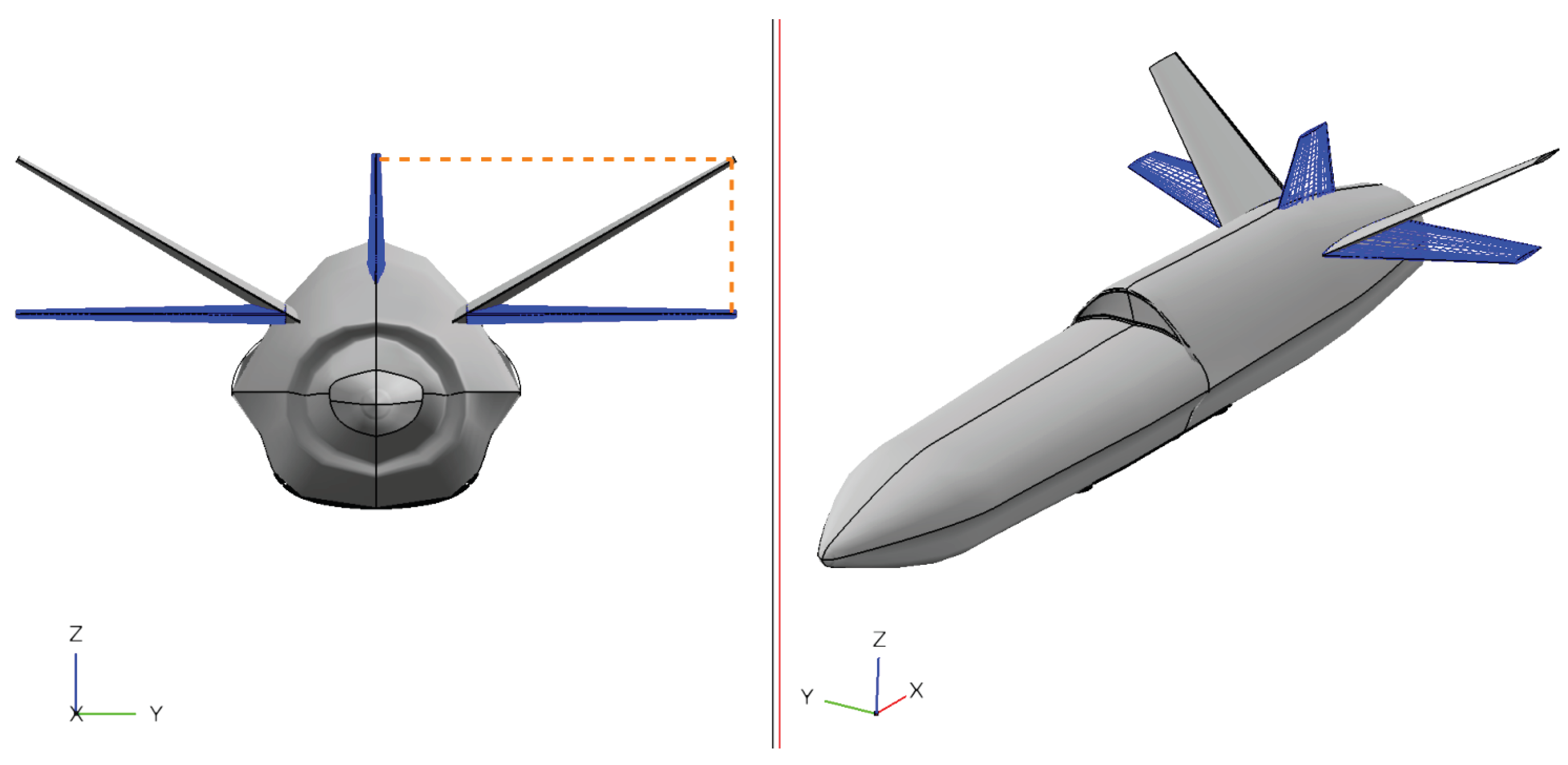
Figure 15.
Adjustment from a conventional (blue tail) to a V-tail (gray tail) configuration in OpenVSP
Figure 15.
Adjustment from a conventional (blue tail) to a V-tail (gray tail) configuration in OpenVSP
5.5. Tail Weight
The tail weight estimation utilized a similar approach to the wing. A tail density factor () of 0.06 was selected based on data for fighter aircraft, acknowledging the tail’s crucial role in stability and control during high-speed maneuvers. The material density was assumed to be the same as the wing, which is 5.45 slugs/ft3. The final tail weight is estimated at 15.11 lb representing 0.63% of the total MTOW.
Table 15.
Concentrated V-Tail Specifications
| Parameter | Nomenclature | Quantity |
|---|---|---|
| V-tail MGC | 1.958 ft | |
| V-tail MAC | 2.078 ft | |
| Tail span | 7.85 ft | |
| Tail projection span | 6.546 ft | |
| Tail fin span | 3.925 ft | |
| Root chord | 2.797 ft | |
| Tip Chord | 1.118 ft | |
| Taper ratio | 0.40 | |
| Tail incidence | ||
| Planform area | 15.37 ft2 | |
| V-tail aspect ratio | 2.79 | |
| Dihedral angle | 33.5 | |
| Airfoil section | − | NACA 63A-010 |
| V-tail sweep angle | 33.0 | |
| Thickness-to-chord ratio | 10% | |
| 9% | ||
| Tail type | − | Fixed or adjustable |
6. Preliminary Stability Analysis
The main objective of this section is to confirm the assumptions made regarding the aircraft’s during the tail design (Section 5). The study focuses on the theoretical stability analysis of the UCAV "Tisis," with practical flight testing and validation required for final confirmation of stability characteristics. The analysis aims to ensure that the center of mass follows a trajectory along the longitudinal axis of the UCAV that remains within close proximity to the initially estimated position, tentatively set at 55% of .
6.1. Technical Details
The iterative process begins by placing each component inside the aircraft. The positions of the wing, the wing-stored fuel, the fuselage, and the tail are predefined relative to each other. The remaining components are positioned within the fuselage while considering the following assumptions:
- The payload (total available weight: 522.12 lb) is segmented into three sub-categories: 85% for the jettisoned payload (443.80 lb), 12% for additional subsystems (62.65 lb), and 3% for miscellaneous countermeasures (15.66 lb). The latter includes flare storage, with up to 19 MJU-7 A/B flares fitting within the allocated weight limit [38].
- The landing system weight is estimated based on empirical values for similar manned aircraft, as its precise design remains undetermined.
- The available weight for standard equipment is derived by deducting the other subsystems’ estimated weight from MTOW.
Table 16 presents the final weight distribution and placement of each component as a percentage of MTOW. The trajectory of the throughout the mission profile, from ground loading to the final mission phase, is depicted in Figure 16 and Figure 17. The is shown to shift between 53.02% and 56.17% of the fuselage’s length (Case #1), maintaining a small and acceptable variation around the initially assumed 55% .
To achieve stability, the aerodynamic center must remain aft of the center of mass. The following stability conditions were confirmed:
- Aerodynamic center (): Estimated at 23% of the wing’s MAC, or 12.703 ft from the fuselage’s nose (56.46% of ). This value is based on empirical data and requires validation through wind tunnel testing or CFD simulations.
- Center of gravity (): Ranges between 53.02% and 56.17% of (11.93–12.64 ft).
Since both the upper and lower limits of remain forward of , the aircraft is deemed statically stable across all mission phases.
6.2. Methodology and Optimization Approach
The optimization method employed in this study follows a qualitative, iterative process rather than a formal algorithmic approach. The aircraft layout was refined manually using a spreadsheet-based method (Excel), where component placement was adjusted to satisfy aerodynamic, stability, and structural constraints. The optimization process followed these principles:
- The positions of the wing, wing-stored fuel, and tail were fixed relative to the fuselage based on aerodynamic and structural requirements.
- The engine was placed within the rear fuselage, aligning with the intake and outlet design constraints.
- Additional fuel tanks were positioned near the wing-stored fuel and engine to minimize the complexity and weight of the fuel distribution system.
- The landing gear placement followed empirical best practices, ensuring that the main landing gears were positioned aft of the , with a forward pivoting nose gear.
These constraints naturally shaped the layout of the UCAV, with component positioning iteratively refined until all functional and stability requirements were met. The design process was guided by engineering judgment rather than an automated optimization algorithm, ensuring that the final configuration adhered to practical and operational considerations.
7. Landing System
The UCAV features a retractable tricycle landing system with a single nose wheel and two main wheels positioned aft of the center of gravity. This configuration enhances directional stability, visibility, and crosswind handling while minimizing drag and radar cross-section. Geometric constraints, derived from literature [21,22], ensure safe clearances, including overturn, tipback, tailstrike, and wingstrike prevention angles, as detailed in Table 17.
Landing gear placement was determined iteratively through a trial-and-error process, considering the center of gravity and geometric restrictions. The nose gear is at 19.7% of the fuselage length, while the main gear is at 67%, 2.8 ft from the centerline. Wheel diameters are 7.8 inches (nose) and 10.2 inches (main), subject to future refinement. The main landing gear integrates two inclined struts and a jack, retracting within the fuselage without obstructing the rear wing spar or payload bay, while the nose gear comprises a single strut and jack. The final design of the landing system, while preliminary, represents a balanced approach that considers aerodynamic efficiency and structural feasibility.
8. Final Design
Brief presentation of the landing system and the final conceptual sketch of the aircraft, as designed in [2]. The final design, though functional and kinematically sound, is qualitative at this stage. A more detailed design, including load analysis and precise component dimensions, would occur in a subsequent, detailed design phase that falls beyond the scope of this paper.
Figure 18.
External image of the designed UCAV "Tisis" designed in SolidWorks.
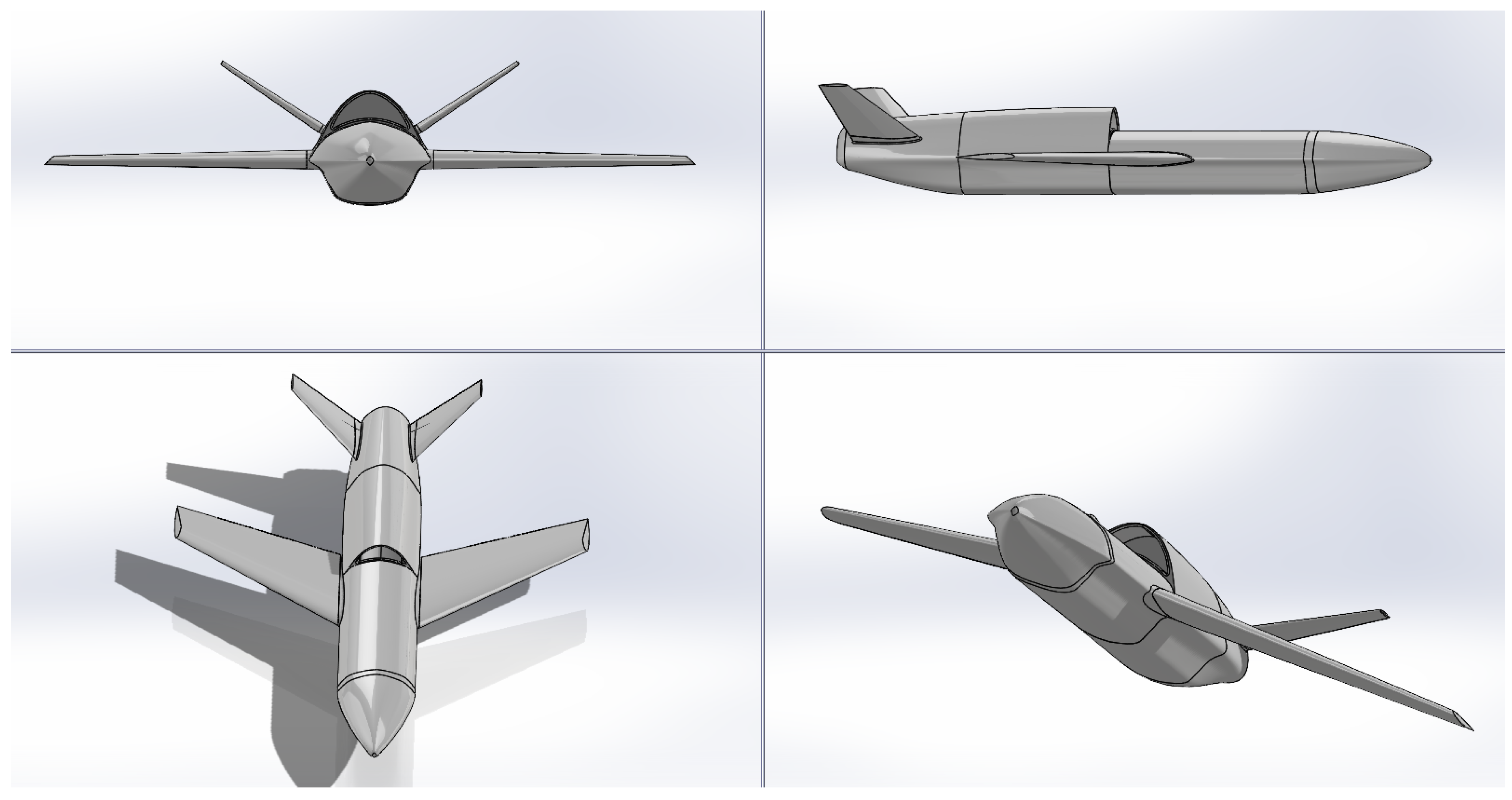
Figure 19.
Left and rear view of the designed UCAV
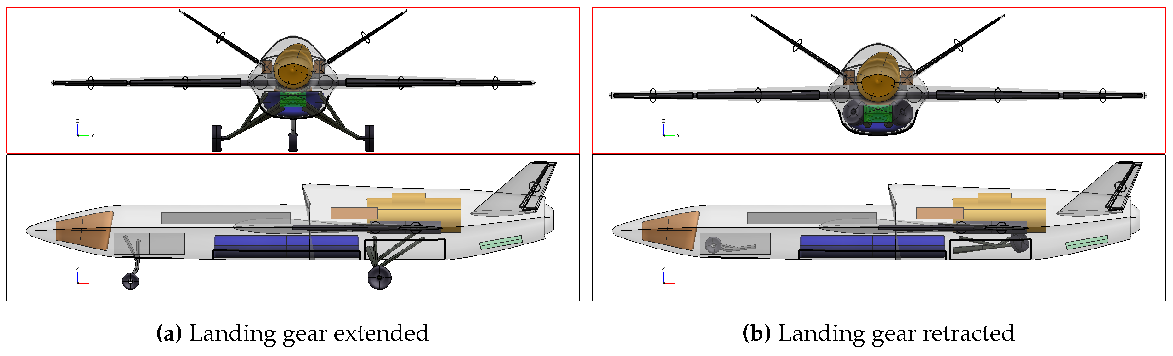
Figure 20.
Left and rear view of the UCAV with dimensions.
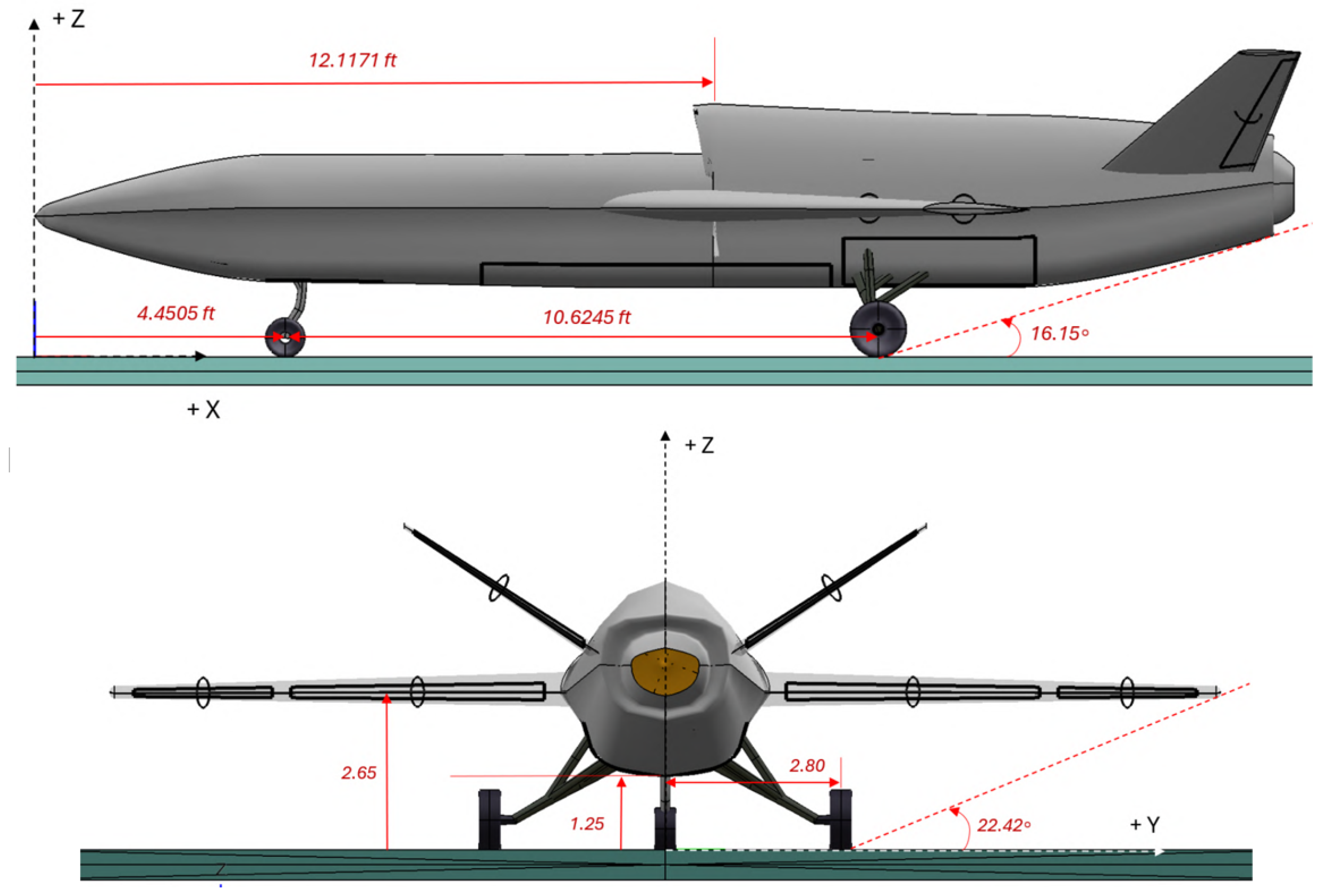
Table 18.
UCAV Specifications
| Parameter | Quantity |
|---|---|
| Wing Configuration | Conventional |
| Wing Type | Fixed |
| High-lift Devices | Single-slot TE Flaps |
| Wing’s geometrical specifications | See Table 14 |
| HLD geometrical specifications | See Table 14 |
| Tail Configuration | V-Tail |
| Tail’s geometrical specifications | See Table 15 |
| Fuselage Length (ft) | 22.50 |
| Fuselage Width (ft) | 3.50 |
| Landing System Configuration | Tricycle |
8.1. Design Considerations for Further Improvement of the Concept
This section outlines potential enhancements to the UCAV’s design. Stealth enhancements focus on reducing radar cross-section (RCS) and infrared signatures. Critical detectability sources include exposed engine fan blades, exhaust plumes, and sharp edges. Mitigation strategies adopt lessons from the XQ-58 Valkyrie (chined fuselage) and F-117 Nighthawk: enclosed bays for gear/payloads, an elevated engine duct, and a trapezoidal fuselage to scatter radar. Future work may integrate radar-absorbent materials or widened exhaust nozzles, pending detailed RCS analysis in subsequent studies.
Aerodynamically, achieving Mach 0.90 at 5,000 ft requires drag reduction and confirmed thrust adequacy. Current tools used (XFLR5, OpenVSP) lack transonic precision [37], but preliminary refinements on Tisis UCAV are underway [39]. Proposed improvements include F/A-18-style wing root extensions for flow separation control and wing fences to limit stall propagation.These features require tailored design and advanced CFD simulations for compatibility. Additionally, weight reduction efforts could target the traditional landing system, with gravity-based mechanisms replacing hydraulics. If applied, trolley-assisted takeoff (XQ-58 method [40]) could further simplify the design.
9. Discussion
The "Tísis" UCAV incorporates several design features aimed at minimizing drag and maximizing aerodynamic efficiency to achieve high-speed performance. Key design choices include:
- V-Tail Configuration: Reduces tail surface area and parasitic drag, beneficial for high-speed flight and potentially lowering RCS. Stability and control trade-offs are acknowledged.
- Internal Payload Bays: Minimize drag and RCS compared to external pylons.
- Retractable Landing Gear: Reduces drag during flight, despite added complexity and weight.
- Fuselage Shaping: A streamlined, compact fuselage with a top-mounted engine inlet minimizes drag and leverages the fuselage’s shape to reduce RCS.
- Wing Design: Optimized sweep angle, taper ratio, and thickness-to-chord ratio to minimize drag, despite limitations in transonic flow modeling with current CFD tools.
The current design focuses on achieving a baseline configuration capable of fulfilling the mission profile while maintaining market competitiveness. Control surfaces are sized based on wing space and stability requirements, ensuring theoretical flight capability. Future refinements, such as optimizing roll and turn rates, can be addressed through additional control devices (e.g., spoilers) or alternative design changes (e.g., fully movable tail surfaces). These measures allow for flexibility in future improvements without requiring a complete redesign.
10. Conclusions
This study developed the conceptual design of the ’Tísis’ UCAV to meet specific mission requirements using established aircraft design methods. The proposed configuration satisfies performance criteria, with future work focusing on technical maturation. Key recommendations include detailed aerodynamic analysis using high-fidelity CFD simulations for accurate transonic modeling near Mach 0.90, as current tools like XFLR5 and OpenVSP lack precision in these conditions [37]. Structural analysis must ensure airframe integrity under operational loads while optimizing critical components like the wingbox and exploring advanced materials.
Wing optimization should refine the planform, airfoil selection, and structural layout, including aeroelastic analyses. Subsequent phases involve detailed subsystem integration (avionics, propulsion, fuel systems) and prototype development for wind tunnel and flight testing. Finally, integrating advanced electronics and AI capabilities - including autonomous flight control, sensor fusion, and secure communications - will ensure operational reliability and interoperability with manned aircraft, enabling the ’Tísis’ to achieve its intended performance goals–and attaching it to the profile of a Loyal Wingman.
Author Contributions
Conceptualization, Savvas Roussos and Vaios Lappas; Methodology, Eleftherios Karatzas; Software, Savvas Roussos; Supervision, Vassilios Kostopoulos and Vaios Lappas; Validation, Eleftherios Karatzas and Vaios Lappas; Writing – original draft, Savvas Roussos.
Funding
This research received no external funding
Conflicts of Interest
The authors declare no conflicts of interest.
Abbreviations
The following abbreviations are used in this manuscript:
| AR | Aspect Ratio |
| CG | Center of Gravity |
| HLD | High Lift Device |
| LBR | Low Bypass Ratio |
| LLT | Lifting Line Theory |
| MAC | Mean Aerodynamic Chord |
| MGC | Mean Geometrical Chord |
| MTOW | Maximum Take-off Weight |
| RCS | Radar Cross Section |
| ROC | Rate of Climb |
| SFC | Specific Fuel Consumption |
| UCAV | Unmanned Combat Aerial Vehicle |
Appendix A
Table A1.
Air and flight characteristics in all altitudes of interest. (Data were calculated parametrically using Sunderland’s method [41,42] and crosschecked through [43])
| Parameter | Take-off & Approach | Cruise | Dash |
|---|---|---|---|
| Altitude [feet] | 0 | 30000 | 5000 |
| Temperature [K] | 298.15 | 238.714 | 288.244 |
| Air Pressure [kPa] | 101325 | 84837.57 | 31493.43 |
| Air Density [slugs/ft3] | 22.9179 | 8.9178 | 19.895 |
| Dynamic Viscosity [kg/(m·s)] | 1.8371 | 1.5402 | 1.7898 |
| Sunderland’s Constant (S) | 110.4 K | ||
| Ambient Temperature (Sealevel) | 298.15 K | ||
| Temperature Lapse Rate*** [K/m] | 0.0065 | ||
| Specific Gas Constant [J/(kg·K)] | 287.05 | ||
| Gravitational Acceleration [m/s2] | 9.80665 | ||
** Calculated using the mean geometric chord as reference. *** Valid up to 11 kilometers in altitude.
Table A2.
Weight range of each component as a percentage of MTOW for various aircraft types [19].
Table A2.
Weight range of each component as a percentage of MTOW for various aircraft types [19].
| Component | Aircraft Category | ||||
|---|---|---|---|---|---|
| Civil Jets | Military Trainers |
Fighters | Military Transport | ||
| Turboprop | Turbofan/Turbojet | ||||
| Structure | 0.270-0.350 | 0.310-0.390 | 0.33-0.35 | 0.250-0.330 | 0.210-0.360 |
| Propulsion System | 0.065-0.075 | 0.140-0.190 | 0.20-0.30 | 0.070-0.110 | 0.050-0.080 |
| Standard Equipment | 0.090-0.130 | 0.150-0.180 | 0.12-0.18 | 0.060-0.100 | 0.040-0.070 |
| Wing Assembly | 0.090-0.140 | 0.070-0.110 | 0.13-0.17 | 0.070-0.130 | 0.090-0.130 |
| Stabilizers | 0.017-0.025 | 0.018-0.026 | 0.09-0.13 | 0.016-0.024 | 0.017-0.019 |
| Fuselage | 0.090-0.120 | 0.090-0.170 | 0.13-0.16 | 0.100-0.130 | 0.060-0.150 |
| Landing System | 0.038-0.045 | 0.040-0.070 | 0.04-0.06 | 0.035-0.045 | 0.035-0.050 |
Figure A1.
Correlation between fuselage length and MTOW for various Class-III UAVs [2]
Figure A1.
Correlation between fuselage length and MTOW for various Class-III UAVs [2]
References
- Castrillo, V.U., Manco, A., Pascarella, D. and Gigante, G., 2022. A review of counter-UAS technologies for cooperative defensive teams of drones. Drones, 6(3), p.65. [CrossRef]
- Roussos, S. Conceptual design of a turbofan – based Loyal Wingman UAV: Towards a Class – III aircraft. Master’s Thesis, University of Patras, Patras, Greece, 2024. [Google Scholar]
- Azman, K.; The First Visuals of TAI ANKA-3 MIUS Have Been Shared! Defence Turk. December 2022. Available online: https://www.defenceturk.net/tusas-anka-3-miusun-ilk-gorselleri-paylasildi (accessed on 17 June 2024).
- Kadidal, A. HAL Loyal Wingman Project to Go Airborne by 2024. Janes. Available online: https://www.janes.com/osint-insights/defence-news/air/hal-loyal-wingman-project-to-go-airborne-by-2024 (accessed on 2 December 2024).
- Baykar. Serial Production of Baykar’s Drone Set to Begin in 2024. June 2023. Available online: https://baykartech.com/en/press /serial-production-of-baykars-drone-set-to-begin-in-2024/ (accessed on 28 May 2024).
- Waldron, G. Australian ‘Loyal Wingman’ to Form Basis of Boeing Skyborg Bid. FlightGlobal, 2021. Available online: https://www.flightglobal.com/defence/australian-loyal-wingman-to-form-basis-of-boeing-skyborg-bid/142239.article (accessed on 13 July 2024).
- Pittaway, N. Ghost Bat Program a Priority. The Australian, 2023. Archived on 25 May 2023.
- The MQ-28A Ghost Bat, Unmanned Systems and the Future of Australian Air Power. YouTube. 2023. Available online: https://www.youtube.com (accessed on 10 August 2023).
- Dassault Aviation. nEUROn. Available online: https://www.dassault-aviation.com/en/defense/neuron/ (accessed on 21 August 2024).
- Miller, D. MiG and Sukhoi to Join Forces on Russian UCAV. FlightGlobal, 2011. Available online: https://www.flightglobal.com/ mig-and-sukhoi-to-join-forces-on-russian-ucav/101484.article (accessed on 21 August 2024).
- TASS. First Flight of Russia’s Heavy Attack Drone Okhotnik Scheduled for 2019. TASS Defense, 2018. Available online: https://tass.com/defense/1012351 (accessed on 21 August 2024).
- Litovkin, N. First Photos Published of Russia’s New Okhotnik Combat Drone. Russia Beyond the Headlines, 2019. Available online: https://www.rbth.com/science-and-tech/329956-first-photos-published-of-russias (accessed on 21 August 2024).
- X-45 J-UCAV (Joint Unmanned Combat Air System). Available online: https://www.airforce-technology.com/projects/x-45-ucav/ (accessed on 16 December 2024).
- X-45 Joint Unmanned Combat Air System. Archived on 23 March 2008. Available online: https://web.archive.org/web/ 20080323161907/http://www.boeing.com/history/boeing/x45_jucas.html.
- International Civil Aviation Organization. *Manual of the ICAO Standard Atmosphere (Extended to 80 Kilometers (262,500 Feet))*, 3rd ed.; Doc 7488-CD; International Civil Aviation Organization: Montreal, QC, Canada, 1993. ISBN 978-92-9194-004-2.
- Rogoway, T. More Details On Kratos’ Optionally Expendable Air Combat Drones Emerge. The Drive. 2017. Archived from the original on 9 June 2023. Available online: https://www.thedrive.com/the-war-zone/7845/more-details-on-kratos-optionally-expendable-air-combat-drones-emerge (accessed on 13 August 2024).
- Liptak, A. ‘Skyborg’ Could Let F-35 and F-15 Fighter Jets Control Their Own Companion Drones. The Verge, 2019. Available online: https://www.theverge.com/2019/5/22/18635935/skyborg-f35-f15-fighter-jets-control-companion-drones-air-force. (archived on 7 January 2024; accessed on 23 May 2019).
- Mizokami, K. The Air Force’s New Weapon Is…Shipping Containers? Popular Mechanics, 2020. Available online: https://www.popularmechanics.com/military/a31171784/air-force-shipping-containers/. (archived on 8 November 2023; accessed on 6 May 2022).
- Roskam, I. Airplane Design. Part 1: Preliminary Sizing of Airplanes; Revised: November 4, 2002; DARcorporation: Lawrence, KS, USA, 1985.
- Raymer, D.P. Aircraft Design: A Conceptual Approach, 6th ed.; American Institute of Aeronautics and Astronautics, Inc.: Reston, VA, USA, 2018.
- Sadraey, M.H. Aircraft Design: A Systems Engineering Approach; John Wiley & Sons: Hoboken, NJ, USA, 2012. [Google Scholar]
- Kallinteris, I. Aircraft Preliminary Design. Class Notes, Mechanical Engineering and Aeronautics Department, University of Patras, 2023.
- Jenkinson, L.R. and Marchman, J., Aircraft design projects: for engineering students. Elsevier, 2003.
- Honda Motor Co., Ltd. Honda Aero Engine HF120. 2024. Available online: https://global.honda/en/products/aeroengine/HF120.html (accessed on 3 September 2024).
- PBS Velká Bíteš. Jet Engine PBS TJ200. 2024. Available online: https://www.pbs.cz/en/Products/Aerospace/Aircraft-Engines/Jet-engine-PBS-TJ200 (accessed on 3 September 2024).
- Pratt; Whitney Canada Corp. TYPE-CERTIFICATE DATA SHEET for PW615 Series Engines. Technical Report IM.E.025, Issue 01. European Aviation Safety Agency (EASA), Longueuil, Quebec, Canada. March 2007. Available online: https://www.easa.europa.eu/en/document-library/type-certificates/pw615 (accessed on 3 September 2024).
- Pratt; Whitney Canada Corp. TYPE-CERTIFICATE DATA SHEET for PW617 Series Engines. Technical Report IM.E.125, Issue 02. European Aviation Safety Agency (EASA), Longueuil, Quebec, Canada. May 2017. Available online: https://www.easa.europa.eu/en/document-library/type-certificates/pw617 (accessed on 3 September 2024).
- Williams International. The Williams Fanjet Family. 2024. Available online: https://www.williams-int.com/products/ (accessed on 3 September 2024).
- Hyvor Talk. Iran’s 1st Turbofan Engine: Jahesh-700. Iran Press, 28 May 2022. Available online: https://iranpress.com/irans-1st-turbofan-engine-jahesh-700 (accessed on 10 September 2024).
- Melin, T. Parametric Airfoil Catalog, Part II: Göttingen 673 to YS930—An Aerodynamic and Geometric Comparison Between Parametrized and Point Cloud Airfoils; 2013.
- Airfoil Tools. Airfoil Database and Tools. Accessed: 14 June 2024. Available online: http://airfoiltools.com (accessed on 14 June 2024).
- Katsamanis, Z. Conceptual design and construction of a small canister based deployable UAV from composite materials. Master’s Thesis, University of Patras, Patras, Greece, 2024. [Google Scholar]
- Gudmundsson, Snorri. General aviation aircraft design: Applied Methods and Procedures. Butterworth-Heinemann, 2013.
- Department of Defense. Standard Practice MIL-STD-3013A. In Glossary of Definitions, Ground Rules, and Mission Profiles to Define Air Vehicle Performance Capability. Department of Defense, Sept. 2008. Approved for public release; distribution is unlimited. Superseding MIL-STD-3013, 14 February 2003.
- Tsien, Hsue-Shen. "Two-dimensional subsonic flow of compressible fluids." Journal of spacecraft and rockets 40, no. 6 (2003): 983-991.
- Liu, Tianshu. "Pressure-correction method for low-speed pressure-sensitive paint measurements." AIAA journal 41, no. 5 (2003): 906-911.
- iforce2d. OpenVSP Tutorial Part 2 (Pitch Moment and L/D Analysis). YouTube Video, 2019. Available online: https://www.youtu- be.com/watch?v=your_video_id (accessed on 2 September 2024).
- N.d. F-22A Beddown Environmental Assessment Elmendorf Air Force Base, Alaska. Technical Report; Approved for Public Release; Distribution Unlimited. 6326 Arctic Warrior Drive, Elmendorf AFB, AK 99506: 3 Civil Engineering Squadron, 3 CES/CC, Elmendorf AFB, Alaska, 2006. Available online: https://apps.dtic.mil/sti/pdfs/ADA634353.pdf (accessed on 10 September 2024).
- Panagos, S. Numerical computational simulation of flow around an aircraft using OpenFoam. Master’s Thesis, University of Patras, Patras, Greece, 2024. [Google Scholar]
- Trevithick, J. XQ-58 Valkyrie Can Now Take Off From Runways Thanks to New Launch Trolley System. The War Zone, 2024. Available online: https://www.twz.com/air/xq58a-valkyrie-can-now-take-off-from-runways (accessed on 3 July 2024).
- Antonios I. Zografos, William A. Martin, and J. Edward Sunderland. Equations of properties as a function of temperature for seven fluids. Computer Methods in Applied Mechanics and Engineering, 61(2): 177–187, 1987.
- W. Sutherland. The viscosity of gases and molecular force. Philosophical Magazine, 36(5): 507–531, 1893.
- The Engineering ToolBox. U.S. Standard Atmosphere vs. Altitude. Available online: https://www.engineeringtoolbox.com/standard-atmosphere-d_604.html (accessed on 10/05/2024).
Figure 1.
Flow chart of the conceptual design process followed in this study
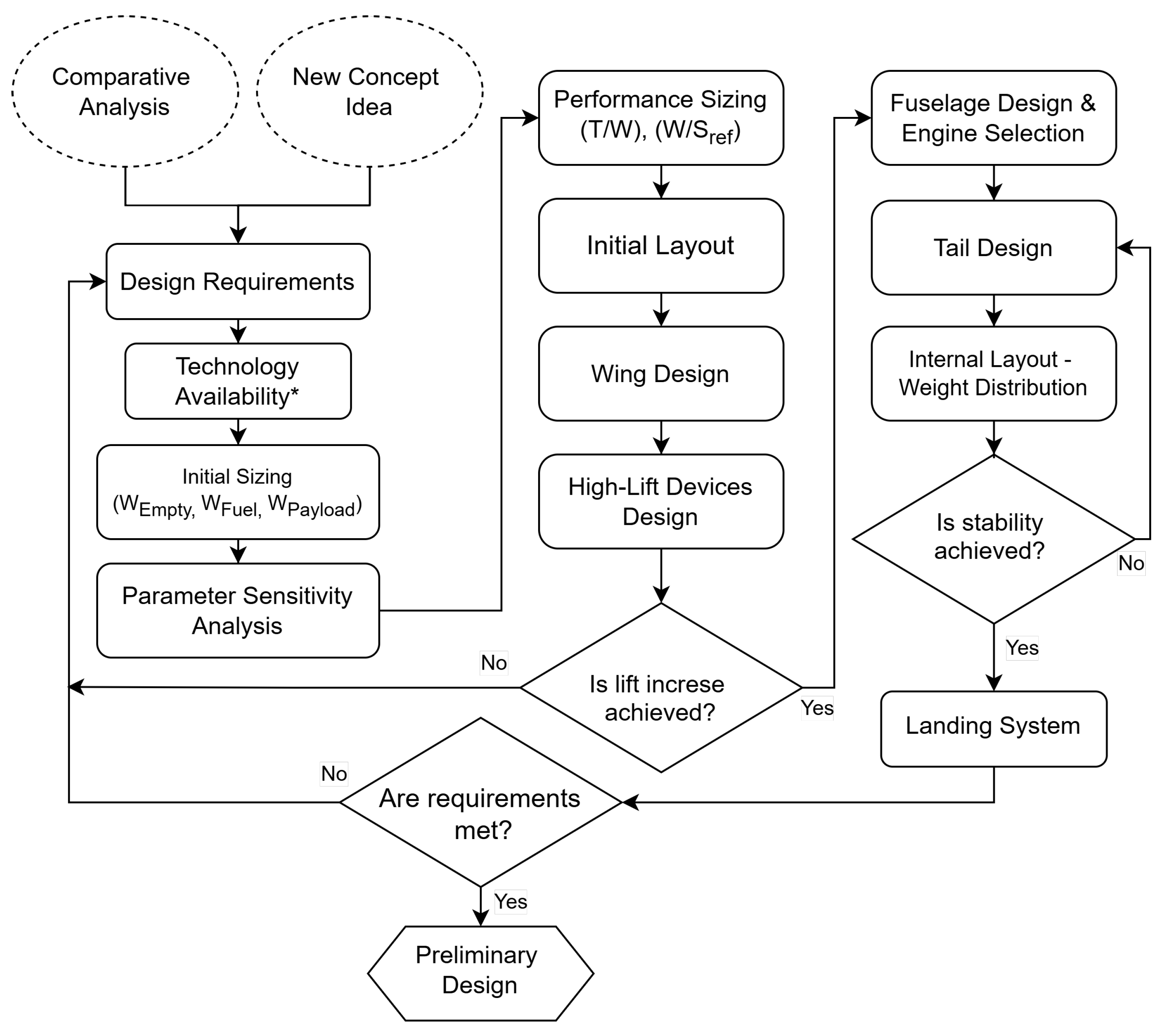
Figure 2.
The scheme of the UCAV’s mission profile.
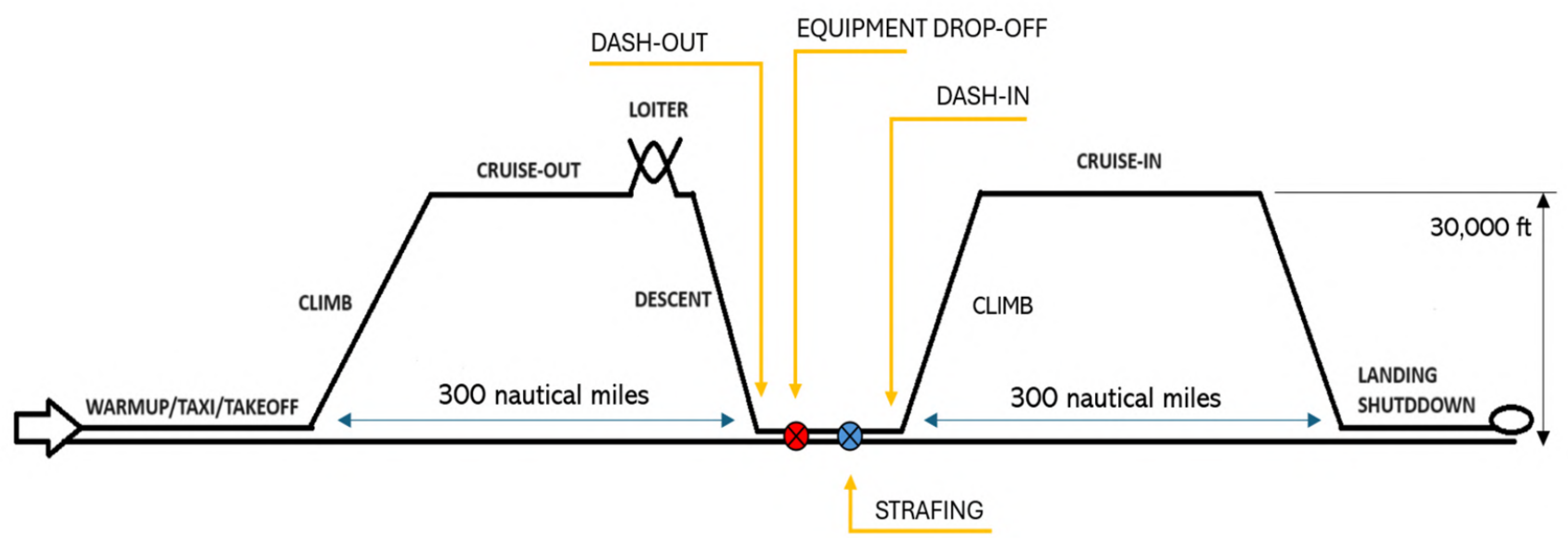
Figure 3.
Acceptable values of (W/S) and (T/W) ratios and the optimal solution for the UCAV
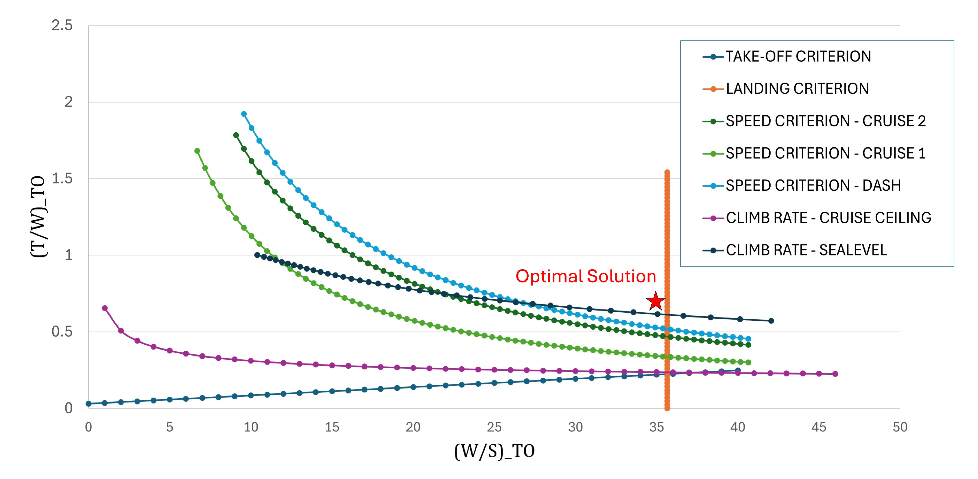
Figure 4.
Aerodynamic properties of proposed airfoils in a cruise-simulated flow phase, produced in XFLR5 software
Figure 4.
Aerodynamic properties of proposed airfoils in a cruise-simulated flow phase, produced in XFLR5 software
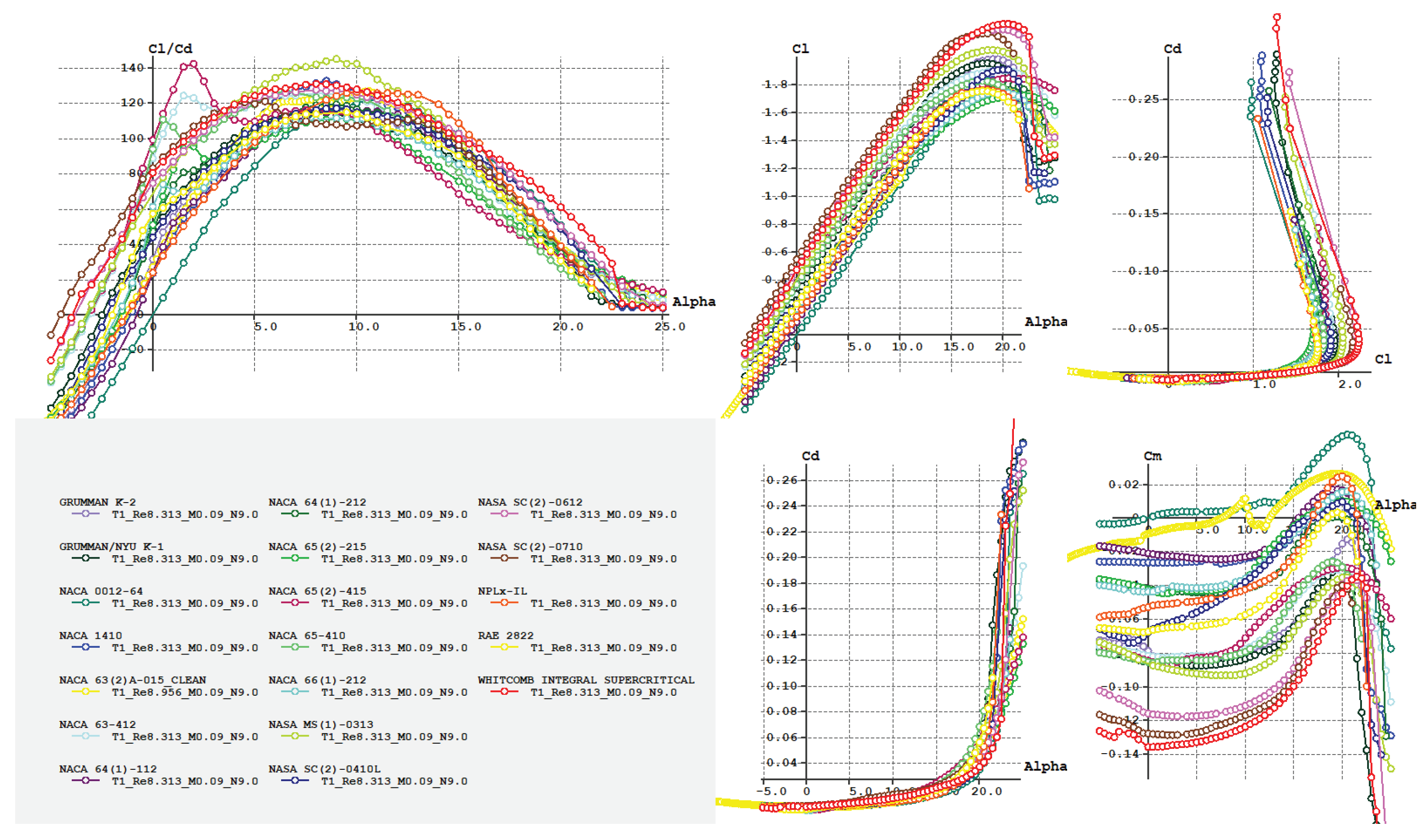
Figure 5.
Local velocity versus reference (infinite) velocity around each airfoil during dash (: 11%, : 10%)
Figure 5.
Local velocity versus reference (infinite) velocity around each airfoil during dash (: 11%, : 10%)
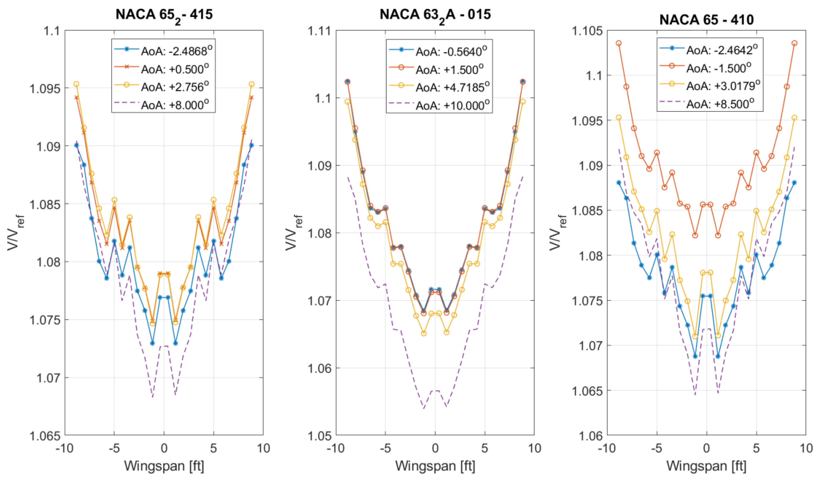
Figure 6.
Moment, lift and drag coefficients as a function of aoa for the three candidate wings at cruise
Figure 6.
Moment, lift and drag coefficients as a function of aoa for the three candidate wings at cruise
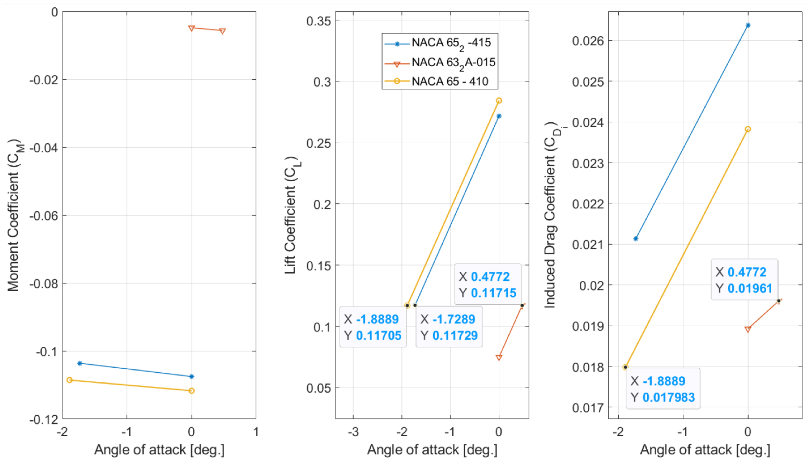
Figure 7.
Comparison between lift, drag and moment coefficients for all 8 configurations of the wing at cruise
Figure 7.
Comparison between lift, drag and moment coefficients for all 8 configurations of the wing at cruise
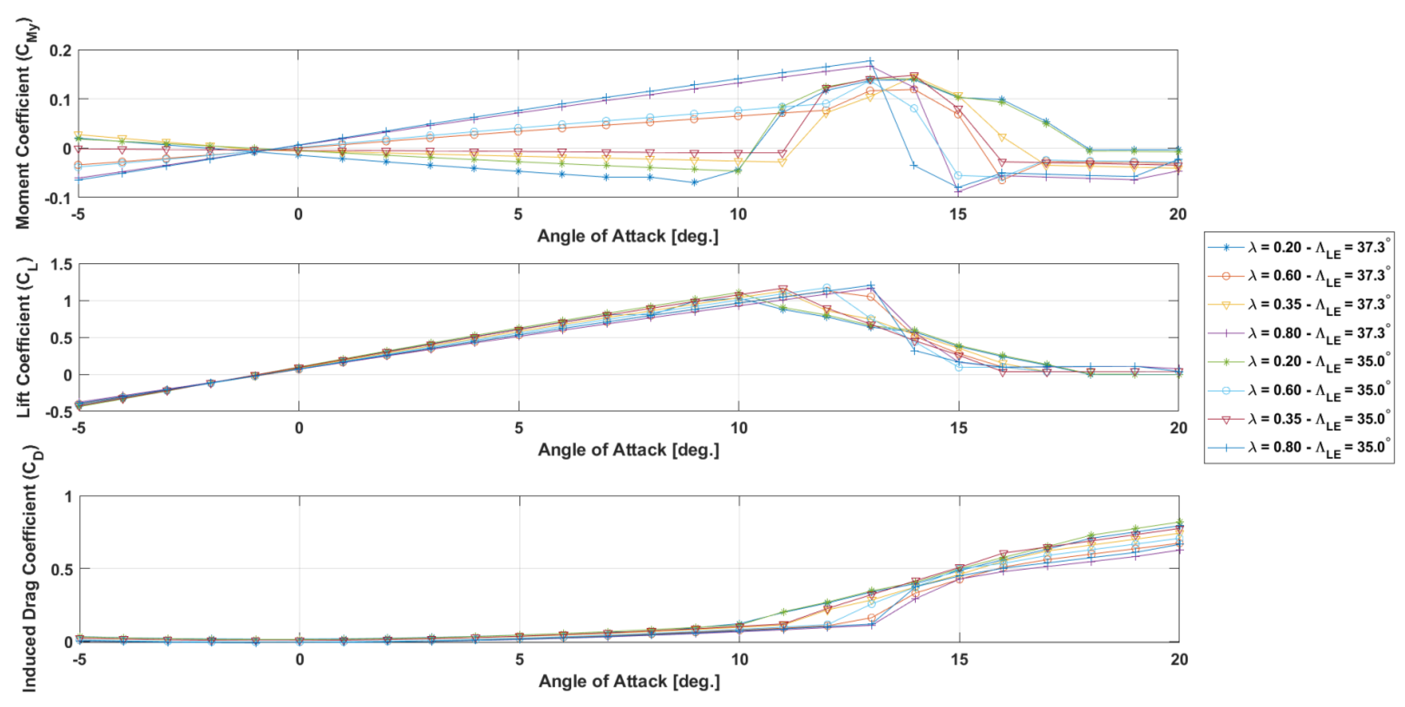
Figure 8.
Wing load factor and sectional lift distribution for all wing configurations, cruise conditions in OpenVSP
Figure 8.
Wing load factor and sectional lift distribution for all wing configurations, cruise conditions in OpenVSP
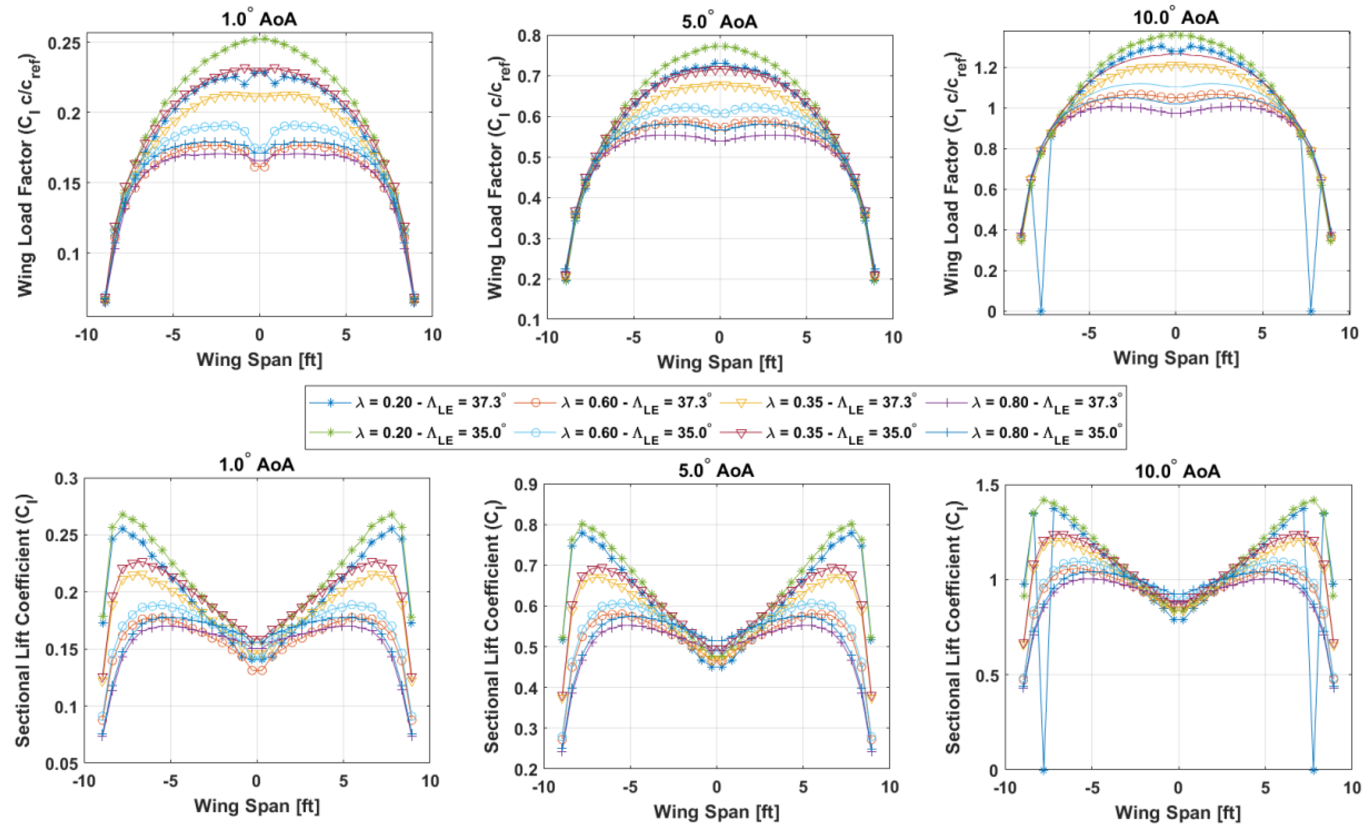
Figure 9.
Wing moment, lift and induced drag coefficient comparison for two cases of taper ratio (twist angle: , )
Figure 9.
Wing moment, lift and induced drag coefficient comparison for two cases of taper ratio (twist angle: , )
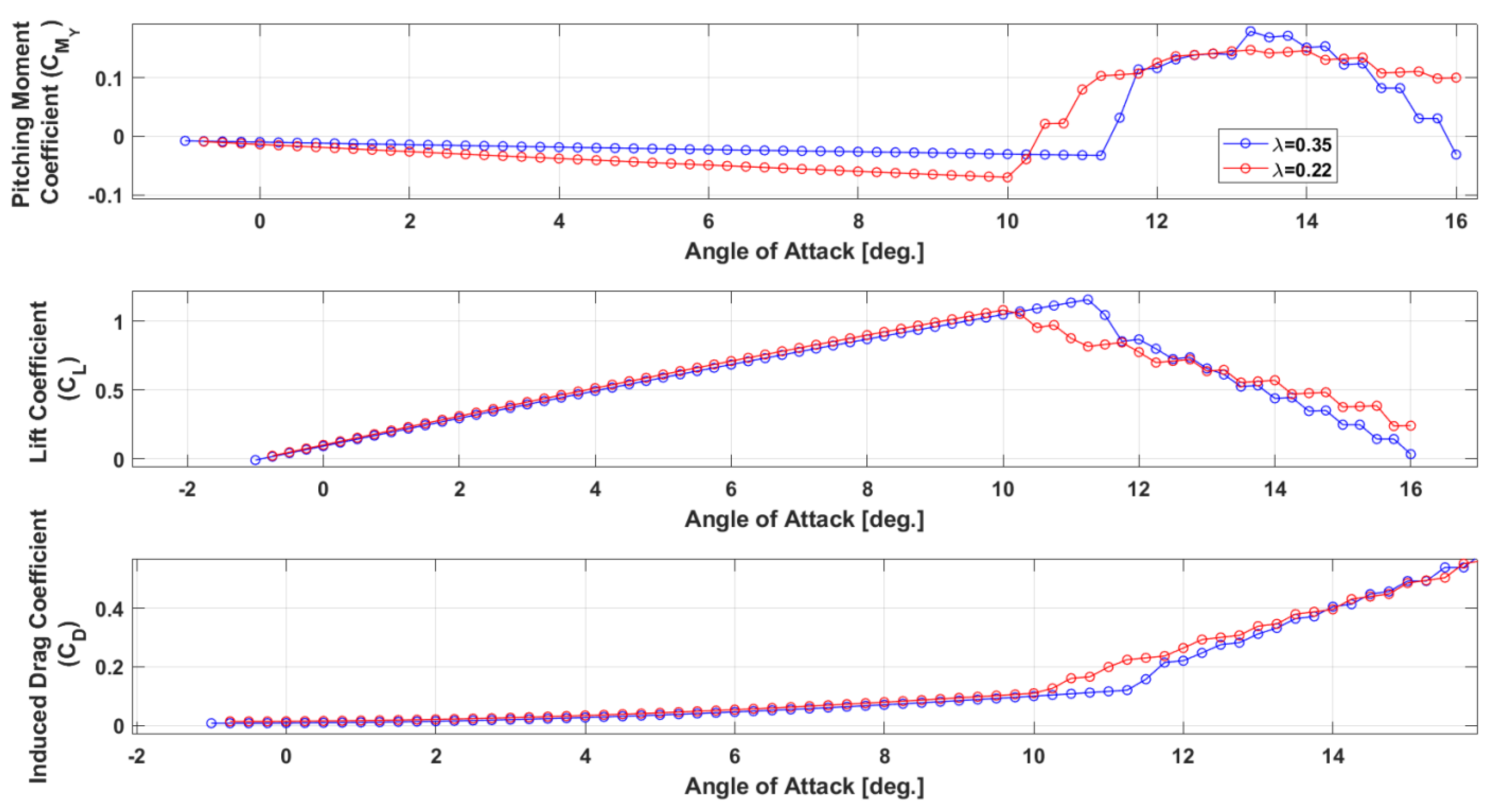
Figure 10.
Wing moment, lift and induced drag coefficient comparison for two cases of tip twist (, )
Figure 10.
Wing moment, lift and induced drag coefficient comparison for two cases of tip twist (, )

Figure 11.
Load factor and sectional lift coefficient across the wingspan during stall for two cases of wing twist (, )
Figure 11.
Load factor and sectional lift coefficient across the wingspan during stall for two cases of wing twist (, )
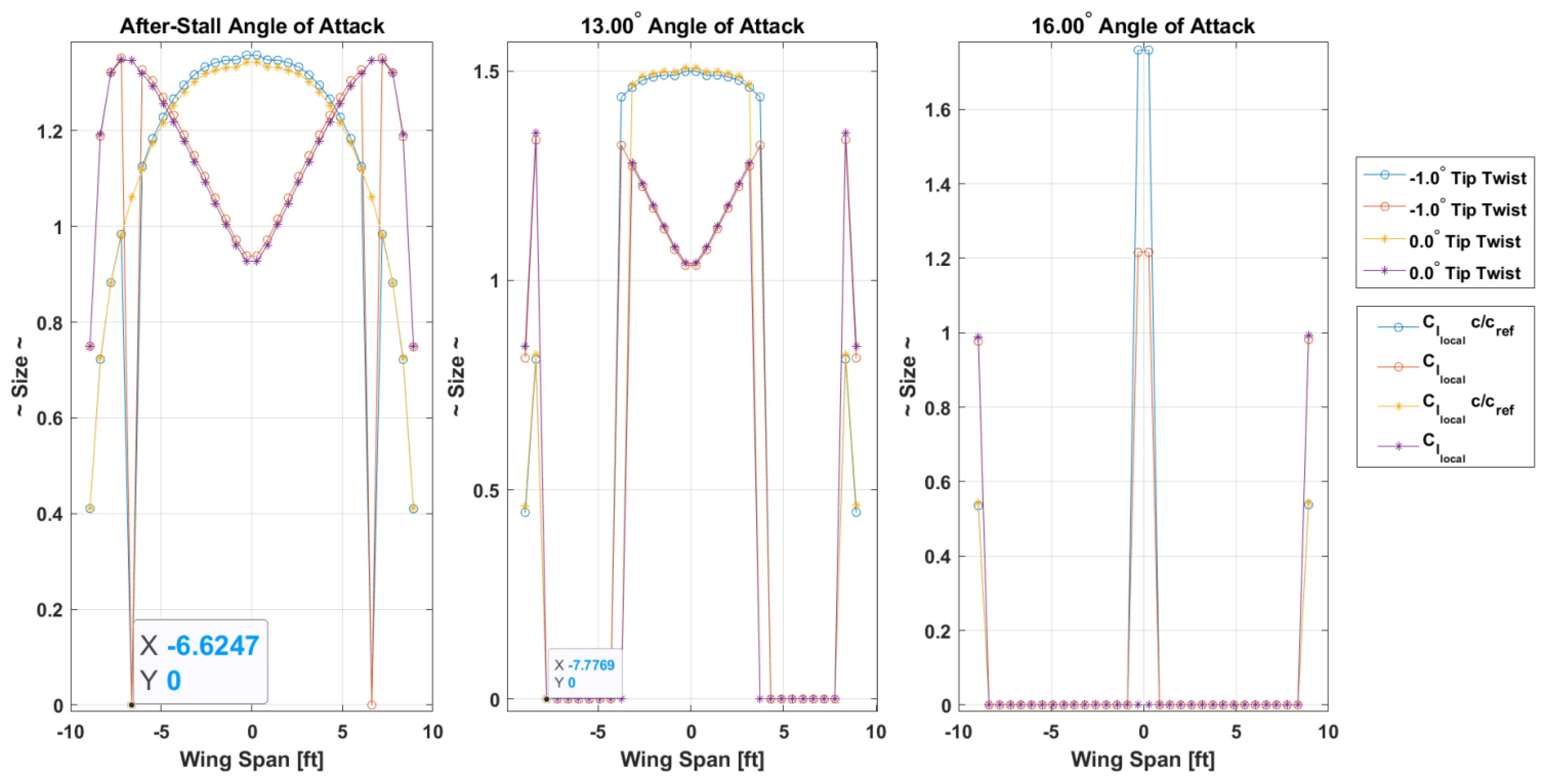
Figure 12.
Wing top-view: Wing/fuselage aerodynamic center distances with respect to the wing geometry
Figure 12.
Wing top-view: Wing/fuselage aerodynamic center distances with respect to the wing geometry
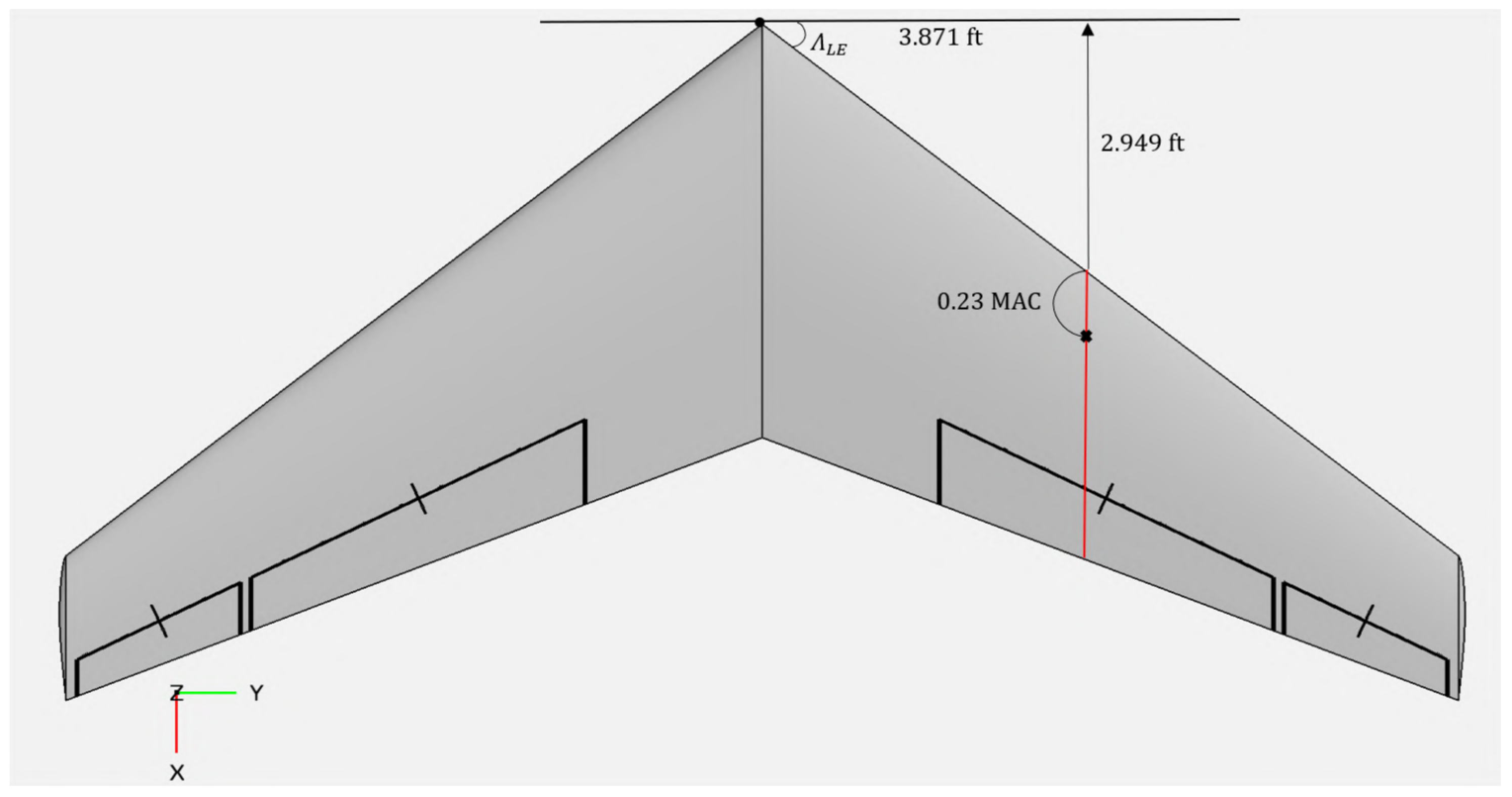
Figure 14.
Transparent side-view and top-view of the UCAV highlighting the internal layout with landing gear extended.
Figure 14.
Transparent side-view and top-view of the UCAV highlighting the internal layout with landing gear extended.
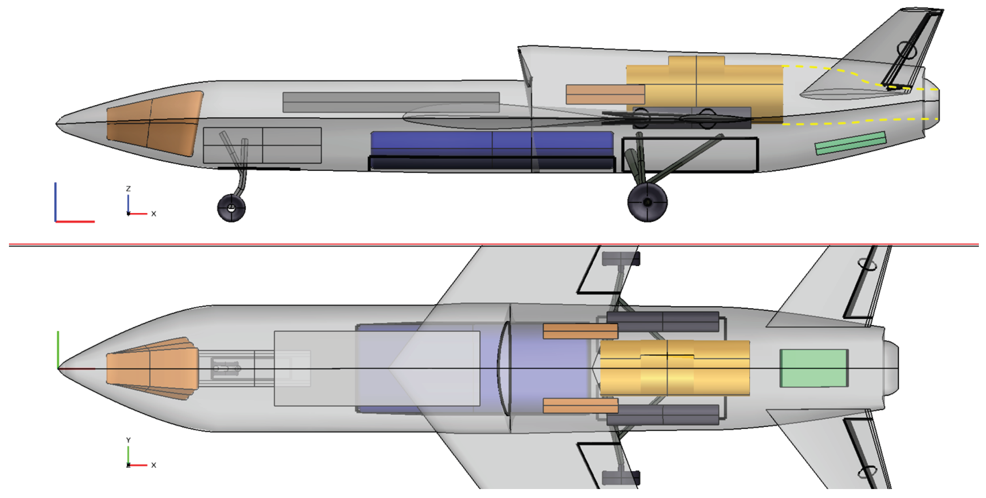
Figure 16.
Center of mass movement along the longitudinal axis of the UCAV during all ground loading and flight phases–Case #1: Disposed Payload
Figure 16.
Center of mass movement along the longitudinal axis of the UCAV during all ground loading and flight phases–Case #1: Disposed Payload
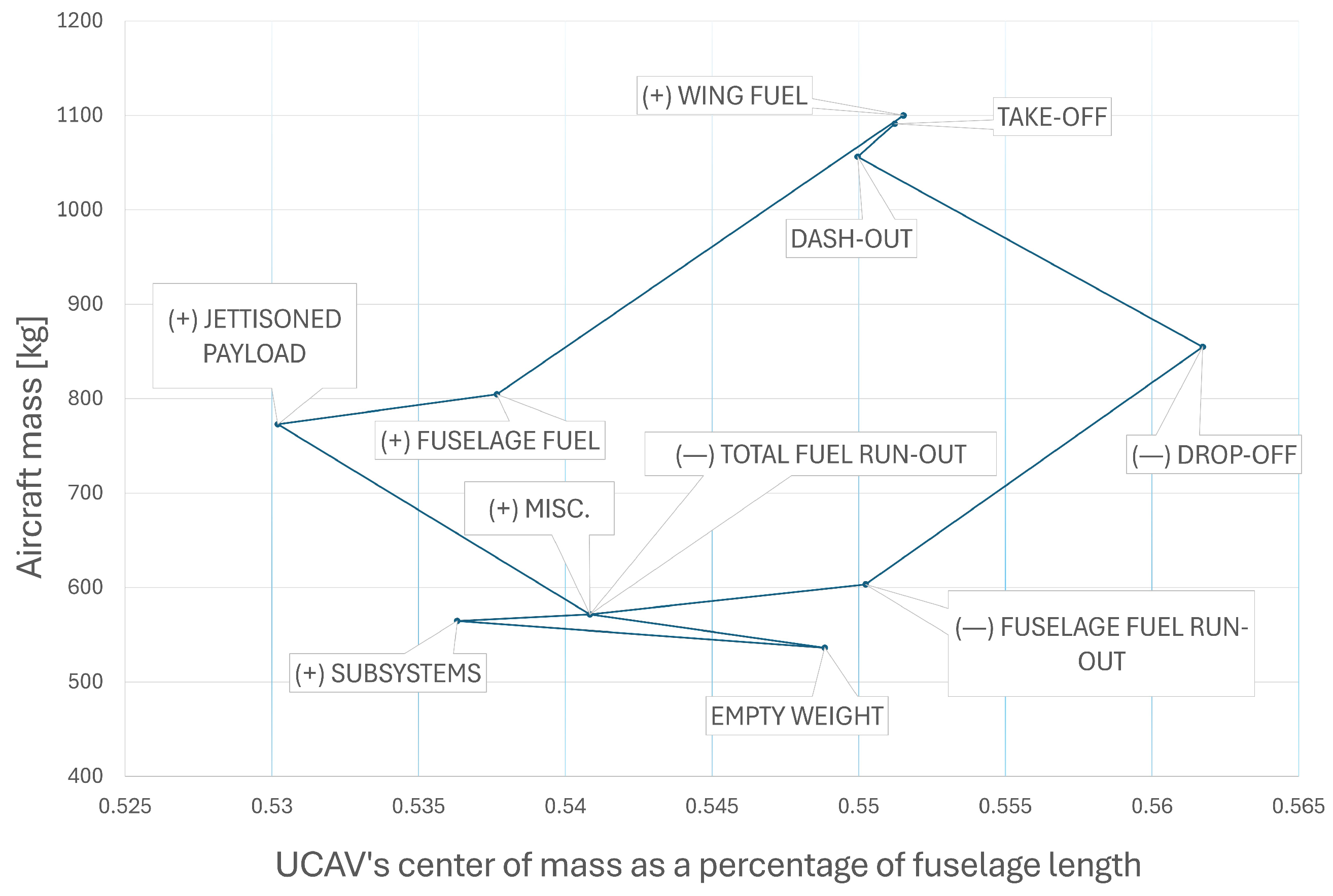
Figure 17.
Center of mass movement along the longitudinal axis of the UCAV during all ground loading and flight phases–Case #2: Kept Payload
Figure 17.
Center of mass movement along the longitudinal axis of the UCAV during all ground loading and flight phases–Case #2: Kept Payload
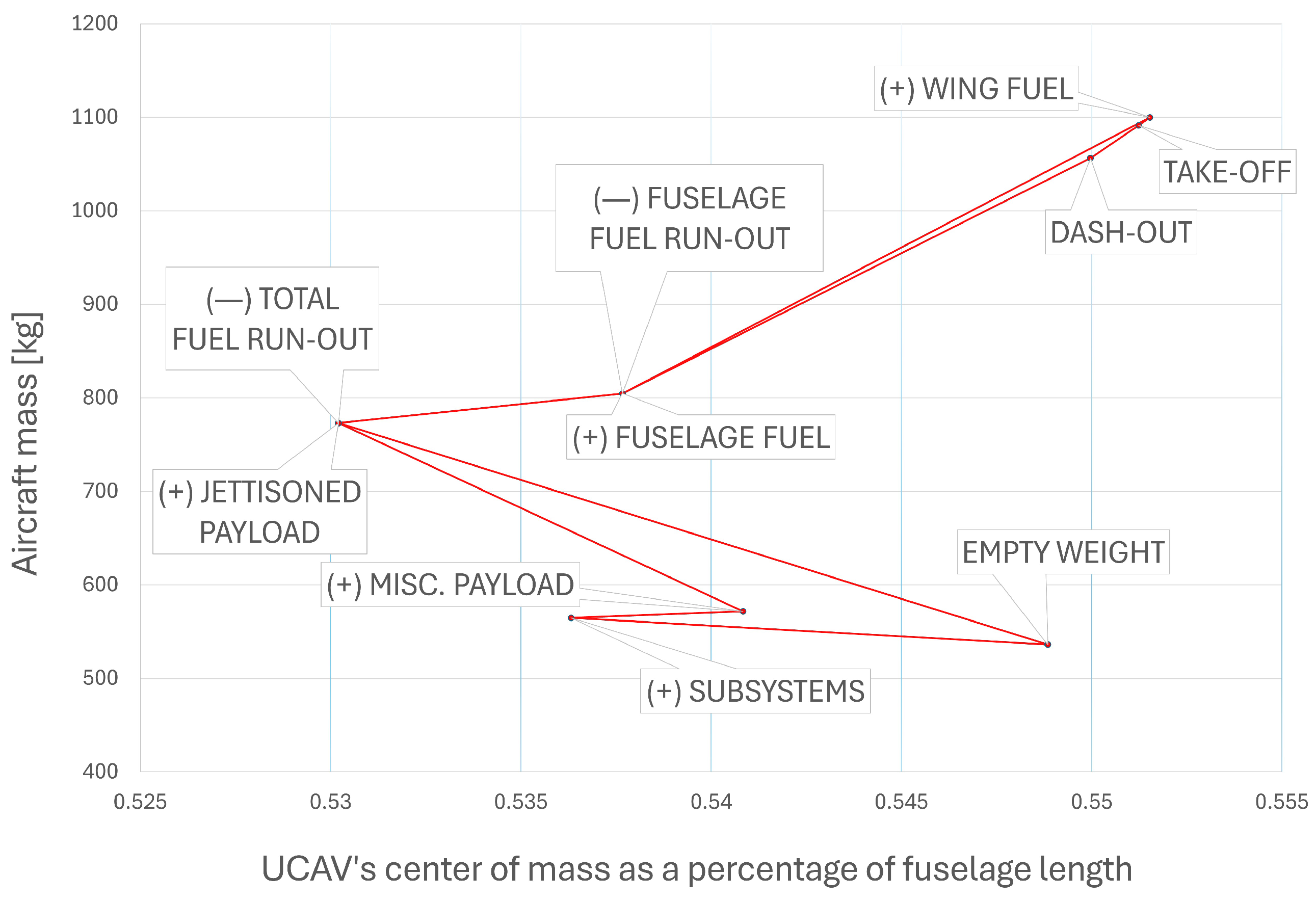
Table 2.
Initial Design Requirements for the "Tísis" UCAV.
| Parameter | Target Quantity | Note |
|---|---|---|
| Gross Weight | 1000 kg ± 10% | Initial Requirement |
| Empty Weight | - | To Be Determined |
| Dash Ceiling | 5000 ft | - |
| Cruise Ceiling | 30000 ft | - |
| Dash Speed | Mach 0.90 | At Dashing Altitude |
| Cruise Speed | Mach 0.80 | At Service Altitude |
| Range | 300 Nautical Miles | - |
| Loitering Endurance | 20 minutes | - |
| Payload Weight | >20% | Percentage of MTOW |
| Take-off Groundrun Distance | ≤ 1000 ft | MIL-STD-3013A |
| Total Landing Distance | ≤ 1000 ft | MIL-STD-3013A |
| Climb Duration | 10 minutes | Clean Configuration |
| Engine Type | Turbofan | - |
Table 3.
Considered quantities for the initial sizing in all mission phases
| i. | Mission Phase | SFCi (lbs/hr/lbf) | (L/D) | Fuel Ratio fi |
|---|---|---|---|---|
| 1 | Engine Warm-up | - | - | 0.99 |
| 2 | Taxiing | - | - | 0.99 |
| 3 | Take-off | - | - | 0.99 |
| 4 | Climb | - | - | 0.97 |
| 5 | Cruise-out | 0.7392 | 5.50 | 0.952 |
| 6 | Loiter | 0.7000 | 9.00 | 0.9619 |
| 7* | Descend-1 | - | - | 1.00 |
| 8* | Dash-out | 0.8000 | 5.50 | 0.9884 |
| 9 | Drop-off | - | - | 1.00 |
| 10 | Strafing | 0.9000 | 4.00 | 0.9814 |
| 11 | Dash-in | 0.8000 | 5.50 | 0.9884 |
| 12 | Climb | - | - | 0.97 |
| 13 | Cruise-in | 0.7392 | 5.50 | 0.9511 |
| 14 | Descend-2 | - | - | 0.9925 |
| 15 | Landing & Engine Switch-off | - | - | 0.995 |
* Phases 7 and 8 are combined for the design process.
Table 4.
Initial sizing results for 3 cases of MTOW
| Run 1 | Run 2 | Run 3 | ||||
|---|---|---|---|---|---|---|
| [lb] | [kg] | [lb] | [kg] | [lb] | [kg] | |
Table 5.
Concentrated results of the parameter sensitivity analysis
| Parameter | Breguet Partials (lbs/unit) | ||
|---|---|---|---|
| Range Case | Endurance Case | ||
| Range R [nautical miles] | Cruise-out | – | |
| Cruise-in | |||
| Dash-out | |||
| Dash-in | |||
| Endurance E [hours] | Loitering | – | |
| Specific Fuel Consumption ci | Cruise-out | – | |
| Cruise-in | |||
| [lb/lbf/hr] | Dash-out | ||
| Dash-in | |||
| Loitering | – | ||
| (L/D) | Cruise-out | – | |
| Cruise-in | |||
| Dash-out | |||
| Dash-in | |||
| Loitering | – | ||
Table 6.
Standard values of the increase in parasite drag coefficient and the change in Oswald’s coefficient with deployed HLD and landing gear [22]
Table 6.
Standard values of the increase in parasite drag coefficient and the change in Oswald’s coefficient with deployed HLD and landing gear [22]
| Layout | Oswald’s Coefficient e | |
|---|---|---|
| Clean Flight | 0.0 | 0.85 |
| HLD - Take-Off Configuration | 0.010–0.020 | 0.80 |
| HLD - Landing Configuration | 0.055–0.075 | 0.75 |
| Landing Gear Deployed | 0.015–0.025 | No effect |
Table 7.
Estimated increase in parasitic drag coefficient due to compressibility [22]
Table 7.
Estimated increase in parasitic drag coefficient due to compressibility [22]
| Flight Speed (knots) | Altitude (feet) | |
|---|---|---|
| 481.65 (Mach 0.80) | 30000 | 0.0010 |
| 595.42 (Mach 0.90) | 5000 | 0.0025 |
Table 8.
Drag Polars and Oswald’s coefficient for all flight phases of interest
| Phase | Oswald’s Coefficient e | Drag Polars | |
|---|---|---|---|
| Take–Off | 0.80 | 0.0536 | 0.0796 |
| Landing | 0.75 | 0.0686 | 0.0849 |
| Cruise | 0.85 | 0.0196 | 0.0749 |
| Dash | 0.85 | 0.0211 | 0.0749 |
Table 9.
Minimum required wing reference area and engine thrust along with the prevailing (T/W) and (W/) ratios.
Table 9.
Minimum required wing reference area and engine thrust along with the prevailing (T/W) and (W/) ratios.
| Iteration | |||||
|---|---|---|---|---|---|
| Input | Calculated | [lbf] | [ft2] | ||
| #1 | 0.6928 | 50.0000 | 35.6428 | 1680.22 | 68.04 |
| #2 | 0.6119 | 35.6428 | 35.6428 | 1483.95 | 68.04 |
Table 10.
Reviewed candidate LBR turbofan engines for the UCAV
| Engine Model | Specifications | |||||
|---|---|---|---|---|---|---|
| Length (in.) | Diameter (in.) | Max. Thrust (lbf) | Dry Weight (lb) | SFC (lb/lbf/hr) | Bypass Ratio | |
| GE-Honda HF120 [24] | 59.5 | 30.51 | 2095 | 466 | < 0.7 | 2.9:1 |
| PBS TJ200 [25] | 27.74 | 9.68 | 512.5 | 61.73 | – | – |
| PW615 [26] | 49.5 | 30.0 | 1460 | 308.6 | – | 2.8:1 |
| PW617 [27] | 54.0 | 30.0 | 1891 | 379.2 | – | 2.7:1 |
| Williams FJ33-5A [28] | 47.9 | 24.75 | 1846 | 319 | 0.486 | – |
| Jahesh-200 [29] | – | – | 1543.2 | 459.3 | ∼0.486 | - |
Table 11.
Ideal lift coefficient at cruise and maximum required lift coefficient for the UCAV
| Lift Coefficient | Mean Quantity | |||
|---|---|---|---|---|
| Cruise-out | Cruise-in | Dash-out | Dash-in | |
| Aircraft ideal () | ||||
| Wing ideal () | ||||
| Airfoil ideal () | ||||
| Aircraft Max. () | ||||
| Wing Max. () | ||||
| Airfoil Gross Max. () | ||||
| Lift-coefficient change due to HLD () | ||||
| Maximum lift coefficient () | ||||
Table 12.
Prevailing candidate airfoils’ aerodynamic performance produced by XFLR5 during cruise. The stall quality is described when simulated in the ’approach’ conditions.
Table 12.
Prevailing candidate airfoils’ aerodynamic performance produced by XFLR5 during cruise. The stall quality is described when simulated in the ’approach’ conditions.
| Airfoil | Stall Quality | ||||||
|---|---|---|---|---|---|---|---|
| NACA 1410 | 0.00505 | 132.32 | 6.34 rad−1 | Moderate | |||
| NACA 632(A) - 015 | 0.00448 | 125.38 | 6.09 rad−1 | Docile | |||
| NACA 63 - 412 | 0.00413 | 123.99 | 6.33 rad−1 | Docile | |||
| NACA 652 - 415 | 0.00361 | 142.06 | 6.24 rad−1 | Docile | |||
| NACA 65 - 410 | 0.00435 | 127.03 | 6.17 rad−1 | Docile | |||
| NASA SC1 - 0410 | 0.00497 | 116.73 | 5.54 rad−1 | Sharp |
Table 13.
The aoa where each wing produces the ideal lift coefficient during dash and cruise
| Wing | aoa at Dash | aoa at Cruise |
|---|---|---|
| ( ) | ( ) | |
| NACA 65-410 | ||
| NACA 65(2)-415 | ||
| NACA 63(2)A-015 |
Table 14.
Concentrated Main Wing Specifications
| Wing Parameter | Nomenclature | Value |
|---|---|---|
| Aspect Ratio | AR | 5.0 |
| Leading Edge Sweep Angle | 37.3° | |
| Quarter Chord Sweep Angle | 33.6° | |
| Taper Ratio | 0.35 | |
| Wing Span | b | 18.444 ft |
| Mean Geometric Chord | C or | 3.689 ft |
| Mean Aerodynamic Chord | MAC | 3.974 ft |
| Wing Reference Area | 68.039 ft2 | |
| Root Chord | 5.465 ft | |
| Tip Chord | 1.913 ft | |
| Max. Thickness-to-Chord Ratio (Root) | 0.12 | |
| Max. Thickness-to-Chord Ratio (Tip) | 0.11 | |
| Airfoil Section | – | NACA 632A–015 |
| High-Lift Devices’ Specifications | ||
| Type | – | Single-slotted flaps |
| Flap-to-wing chord ratio | 0.25 | |
| Span | (0.68–0.22)·b/2 | |
| Deflection at Takeoff | 16 | |
| Max. Deflection | 40 | |
Table 16.
Center of mass estimation for all individual components–Final Iteration.
| UAV Component | Weight Fraction (100% ) | Mass [lb] | Relative Distance from Reference Point (%) | |
|---|---|---|---|---|
| Engine | 13.15% | 319 | 72% | |
| Fuel | Wing-stored | 26.85% | 651.13 | 58.93% |
| Fuselage-stored | 2.88% | 69.74 | 72% | |
| Payload | Subsystems | 2.58% | 62.65 | 30% |
| Disposable | 18.30% | 443.80 | 50% | |
| Miscellaneous | 0.65% | 15.66 | 90% | |
| Fuselage | 8.36% | 202.81 | 55% | |
| Main Wing | 6.00% | 145.51 | 59.37% | |
| Tail | 0.63% | 15.11 | 91.84% | |
| Landing System | 4.00% | 97.00 | 55% | |
| Standard Equipment | 16.53% | 400.93 | 38% | |
Table 17.
Landing system geometry restriction angles
| Angle | Nomenclature | Calculated Value | Restriction |
|---|---|---|---|
| Overturn Angle | 45.86 | ||
| (Stringiest) | 54.96 | ||
| 35.04 | |||
| Tip-back Angle | 41.87 | ||
| Tail-strike Angle | 16.14 | ||
| Wing-strike Angle | 22.42 |
Disclaimer/Publisher’s Note: The statements, opinions and data contained in all publications are solely those of the individual author(s) and contributor(s) and not of MDPI and/or the editor(s). MDPI and/or the editor(s) disclaim responsibility for any injury to people or property resulting from any ideas, methods, instructions or products referred to in the content. |
© 2025 by the authors. Licensee MDPI, Basel, Switzerland. This article is an open access article distributed under the terms and conditions of the Creative Commons Attribution (CC BY) license (http://creativecommons.org/licenses/by/4.0/).
Copyright: This open access article is published under a Creative Commons CC BY 4.0 license, which permit the free download, distribution, and reuse, provided that the author and preprint are cited in any reuse.


