

Submitted:
13 May 2025
Posted:
14 May 2025
You are already at the latest version
Abstract
A single paragraph of about 200 words maximum. For research articles, abstracts should give a pertinent overview of the work. We strongly encourage authors to use the following style of structured abstracts, but without headings: (1) Background: place the question addressed in a broad context and highlight the purpose of the study; (2) Methods: describe briefly the main methods or treatments applied; (3) Results: summarize the article’s main findings; (4) Conclusions: indicate the main conclusions or interpretations. The abstract should be an objective representation of the article, it must not contain results which are not presented and substantiated in the main text and should not exaggerate the main conclusions.
Keywords:
handling qualities
; certification
; simulation
; Uncertainty Analysis
; eVTOL
; UAM
1. Introduction
Integrating vertical take-off and landing (VTOL) vehicles into urban airspace comes with enormous challenges from a design and technological standpoint, and considering the necessary certification efforts. Demonstrating compliance with the flight-related airworthiness rules set by aviation authorities is indeed one of the most critical phases of the vehicle development process: the evidence collection and compliance demonstration processes, which are primarily based on flight testing activities, are highly complex, very time demanding, and require a lot of effort to minimise safety risks while keeping the representativeness of the flight test. Certification may become even more difficult in the context of Urban Air Mobility (UAM), where the safety of eVTOL operations needs to be fully assessed and understood1. Therefore, appropriate means of compliance (MoC) and guidelines for the certification of this class of vehicles are still under development. In the publication of the MoC for the SC-VTOL Standard, the European Union Aviation Safety Agency (EASA) in MOC VTOL.2500(b) states that flight simulators "may also support some certification tests" [1], explicitly allowing the possibility of exploit simulators as an alternative to flight tests under specific conditions and when appropriate means are undertaken.
1.1. VTOL Handling Qualities Regulatory Framework
The certification of aircraft configurations, which differs from conventional rotorcraft or fixed-wing aircraft, requires special care. EASA decided to tackle the unique characteristics of these aircraft that have lift/thrust units through the definition of a complete set of dedicated technical specifications in the form of a special condition for VTOL-capable aircraft, that culminated in the publication by EASA of Special Condition for small-category VTOL aircraft (SC VTOL) [2]. This standard, which descends directly from EASA’s CS-23 and CS-27, is articulated in different subparts and covers a wide range of rules, ranging from stall characteristics and flight envelope definition to handling qualities (HQ) assessment. The topic of VTOLs HQ certification takes on particular importance, because adequate HQs lead to a limited pilot workload and sufficient spare capacities that provide full situational awareness and so a higher level of safety. To this aim, three specific rules of the SC-VTOL deal directly with HQs: VTOL.2135 Controllability, VTOL.2140 Control Forces, and VTOL.2145 Flying Qualities. The role of each rule and the relationship with the different aspects of the piloted flight are described in Figure 1.
VTOL.2135 rule [2] explicitly focuses on controllability and manoeuvrability. Controllability links pilot control inputs to the resulting aircraft response and combines VTOL inherent properties with the mechanical characteristics of control inceptors. In quantitative terms, it measures the levels of compensation required to hold a given flight condition and the availability of control margins. On the other hand, manoeuvrability can be defined as a performance of the aircraft, representing its ability to transition from one trim condition to another. VTOL.2145 puts the accent on VTOL stability, referring to its tendency, either initial (i.e. static stability) or long-term (i.e. dynamic stability), to return to its trim condition after undergoing an external disturbance. Figure 1 shows that the aforementioned rules are not separate but have several intersection points. Stability and manoeuvrability are indeed intrinsic aircraft properties; as such, they contribute to defining the aircraft’s flying qualities. On the other hand, the HQ should consider the pilot in the loop, taking into account the capability to perceive correctly the state of aircraft using the simulator cues (visual, vestibular, audible, etc.) and perform the required mission tasks without excessive workload that may hinder the performance. So, as expressed by EASA in [1], to comply with VTOL.2135 it is necessary to show that the aircraft possess a satisfactory HQ to "give the opportunity for the crew to better manage high-workload situations, and allow them to operate safely for longer periods, and to be able to deal with aircraft system failures and contingencies." To show compliance with these rules, EASA proposed as a MoC the Modified Handling Qualities Rating Method (MHQRM) [1] where the applicant must demonstrate reaching a minimum acceptable HQ rating for each flight phase and condition that has a probability of being encountered greater than . The suggestion is to use the well-established Cooper-Harper Handling Qualities Rating (CHR) Scale [3], but applicants may choose other scales. The probability of a flight condition is defined by a combination of individual probabilities associated with
- the Flight Envelope (Normal, Operational, Limit) the VTOL operates in, ;
- possible aircraft Failure Conditions (Nominal up to Major, Hazardous), ;
- the level of Atmospheric Disturbances (AD) acting on the vehicle, from total absence of AD up to the ones exciting structural limits (Light, Moderate, Severe), .
EASA drafted standardised tables to help the applicant define individual terms. To obtain the probability, under the assumption of independence of the three factors, these should be combined as follows
Should a clear correlation between the factors exist, the expression shall be modified accordingly.
Therefore, to certify an aircraft according to VTOL.2135, collected evidence based on MHQRM must cover the entire aircraft flight envelope, accounting for failure events and atmospheric disturbances. EUROCAE ED-295 [4] provides some guidance on how to collect the evidence required by the MHQRM. Inspired by the concept of Mission Task Element (MTE) of Ref. [5], ED-295 developed a set of guidelines specifically tailored for VTOLs in the form of Flight Test Manoeuvres (FTM) to be performed with the pilot-in-the-loop. For each FTM the document proposes a set of limits, in terms of desired or adequate performance, that are quantitative measures, specifically tailored to the FTM under study, and aimed at identifying performance deficiencies. Furthermore, a subjective CHR – provided by properly trained test pilots – must follow; it is hence a pilot-assigned evaluation, similarly to Ref. [5] where it is defined as Assigned HQs. MHQRM [1] reinterprets the CHR, presenting three possible HQ levels: Satisfactory, Adequate, and Controllable (Table 1). The ultimate purpose of FTMs is to quantify HQs according to the level of pilot workload considered appropriate for the intended task. As ED-295 highlights, FTMs work on a dual level: first of all, they stress aircraft’s capabilities, looking for possible Flight Control System deficiencies that, combined with an excessive workload request, could severely challenge the pilot ("without exceptional piloting skills"). The performance parameters serve to validate the pilot ranking, as they should correspond to the CHR assigned by the pilot. Secondly, a set of CS-based guidelines ensures repeatability of the tasks and direct comparison between the feedback of different pilots.
To apply the MHQRM approach, a large number of flight tests may be required, with many tests performed in challenging (e.g., outside normal flight envelope or with failures) or difficult to repeat (e.g., atmospheric disturbance) conditions. To reduce the risk, time, and cost of flight test activities for VTOL aircraft, in some scenarios it may be possible to proceed with a demonstration using flight simulators, as suggested by EASA, following an approach called "Certification by Analysis". However, appropriate Flight Simulation Models (FSM) must be developed first, so it is necessary to provide a reliable methodology that leads to such models.
1.2. Certification by Simulation Approach
With the term Certification by Simulation (CbS), we refer to all cases where flight simulation can be used to support, augment or replace flight testing in the demonstration of certification compliance "without sacrificing the level of safety" [6]. This approach, already accepted for helicopters by certification authorities in the past on a case-by-case basis [7,8], has been made systematic and more structured for the certification of rotorcraft under the EASA CS-27 and CS-29 in Ref. [6]. The process presented in Ref. [6] is a structured, requirement-based approach that starts from the definition of the Applicable Certification Rule (ACR) (Phase 1 in Figure 2) and then moves to the subsequent simulation-related phases that allow one to build up the simulation ecosystem composed by the Flight Simulation Model (FSM), the Flight Simulator (FS) the and Flight test activities developed to collect validation data for the FSM and the FS (Phase 2 in Figure 2). In the development of FSMs it is crucial to evaluate the error in comparison with tests, i.e. validate the models, showing that they have a sufficient level of fidelity that translates into an error that is below a certain set of tolerances agreed with the certification authority. However, for certification activities, this is typically not enough, because the models can be used in conditions that cannot be compared with equivalent tests, so it is also necessary to provide evidence of the credibility of the models. The concept of credibility of the predictions made by simulations is somewhat elusive, but it expresses the level of confidence that the users of the FSM have in the fact that the results obtained with the FSM reflect the behavior of the real aircraft.
In Ref. [6] the credibility is managed by the definition of a confidence ratio that is the ratio between the value of the distance between the performance obtained by the FSM and the performance limit allowed for the certification, called the margin M, and the uncertainty U in the prediction of that performance:
where the uncertainty U collects the experimental uncertainty, the uncertainty of input data and parameters of the model, and the numerical uncertainty associated with the method used to solve the mathematical models.
Basically, the users accept that the higher the risk of using the model for certification, defined through the combination of the influence level and the predictability level (see Ref. [6] for more details), the higher the confidence ratio must be (in any case greater than 1). In this way, asking for a margin to be significantly higher than the uncertainty, it is possible to ensure that the predictions have a higher degree of credibility.
The concept of a confidence ratio allows us to keep the credibility of models at the required level; however, it applies only to situations where there is a quantified requirement. In case of ACRs that rely on subjective pilot evaluations based on discrete – and often nonlinear [9] – rating scales, such as the CHR, other criteria must be defined to assess credibility. Since this is exactly the case of HQs certification for VTOLs, this paper will try to extend the concept of CR proposed in Ref. [6] to this case.
1.3. Proposed Approach for Credibility Assessment of a Flight Simulation Model
The first step of a credibility assessment is always composed of the validation and fidelity assessment of the FSM. In principle, since the ACRs in this case require performing a pilot-assigned evaluation, i.e., assigned HQ tests, it is the fidelity of these evaluations that should be the objective of the fidelity assessment and uncertainty quantification. However, we must acknowledge that any quantity measured during these tests will be affected not only by the FSM but also by the FS characteristics and by the test pilot characteristics. As such, it will not represent a measure of the FSM quality. A different approach could be defined by making use of the concept of Predicted HQ defined in Ref. [5]. The predicted HQs (pHQ) are obtained through an open-loop flight test and therefore relate to the intrinsic flying qualities of the aircraft. They are chosen as a way to anticipate how an aircraft will behave in terms of HQ, and in Ref. [5] is used as support for aircraft design, as it is possible to show that helicopters that have certain pHQs are expected to reach a certain level of Handling Quality Rating (HQR) in the aHQ tests. Similar behavior may be expected for VTOLs. As a consequence, it is possible to say that a FSM of a VTOL that shows pHQs sufficiently close to those measured during flight tests is a faithful reproduction of the real aircraft. At the same time, it is possible to assess the level of uncertainty of the FSM by looking at the uncertainty that results in the pHQs.
However, once the uncertainty on the pHQ of the FSM is quantified, it is necessary to understand how it translates into an uncertainty for the aHQs and how the confidence ratio could be taken into account. The process we suggest here is as follows:
- select among the uncertain configurations those that lead to the worst pHQs.
- Compute the transfer functions for these worst configurations (wTFs) and compare them with the nominal transfer function (TF) obtained with the reference model.
- Define new transfer functions that are the nominal transfer function plus the difference between the WTFs and the nominal one, multiplied by the confidence ratio.
If the difference between the nominal TF and the wTFs multiplied by the CR stays within the range of the mismatches that proved unnoticeable to pilots, defined here [10] as MUAD (Maximum Unnoticeable Added Dynamics), it is possible to assume that the results obtained by using the nominal FSM must lead to assigned HQ ratings that have a sufficient degree of credibility. If this is not the case, i.e. the wTFs are beyond the MUAD limits, the model developer has two options:
- Improve the models to reduce the uncertainty and/or reduce the uncertainty in the flight test measures.
- Perform several flight simulator test campaigns using nominal and worst-case models to quantify the impact of uncertainties on the rating for the aHQ.
Of these two options, the former should be the preferred option whenever possible. The latter, in fact, may require a large number of simulated flight tests.
To verify whether this approach is feasible, we will start in this work investigating the relationship that exists between the uncertain models that present the worst pHQs and the corresponding assessment of the aHQ. To avoid blurring the evaluation with subjective pilot evaluations, it has been decided to apply the approach to a drone model in which pilots are replaced by a virtual system that controls the aircraft. So, no flight simulator tests are presented here. The paper is organised as follows: after presenting the aircraft model, the uncertainty quantification analysis is presented to identify the relationship between the uncertainty of the input data and the resulting pHQ. Then, a first set of assigned HQ tests is presented, considering both the reference model and several modified models selected to represent the worst configurations, followed by an analysis of how the transfer functions of the worst cases compare with the MUAD boundaries. Finally, some conclusions are drawn.
2. VTOL Aircraft Description
VTOL aircraft present a wide variety of configurations. In this paper, it has been chosen to investigate the approach to credibility of a flight simulation model using an aircraft in the lift+cruise configuration. Vertical lift is provided by variable rpm propellers that operate during take-off and landing, and low-speed manoeuvres, while forward thrust is generated by separated propellers during cruise flight. EASA developed SC-VTOL for passenger transport with a maximum take-off mass of 3175 kg [2] (up to 9 passengers). However, in the context of this research, it has been decided to perform the certification exercise on a laboratory small-scale prototype to allow for a direct comparison with data from experimental tests.
The aircraft under analysis is a small-scale unmanned eVTOL, designed, manufactured and tested in flight by the Aerospace Systems and Control Laboratory (ASCL) of the Department of Aerospace Science and Technology at the Politecnico di Milano (DAER) [11,12,13] (depicted in Figure 3). It has two distinct sets of rigid propellers for thrust generation: eight fixed-pitch, variable-RPM three-bladed propellers, are responsible for controlling the vehicle in helicopter mode (using differential thrust), while a couple of two-bladed propellers produce forward-flight thrust in aeroplane mode. The baseline structure is of a fixed-wing UAV which features a small-sized fuselage and two rectangular wings with zero built-in twist. The main geometry and performance characteristics are detailed in Table 2.
2.1. Flight Simulation Model Architecture
The FSM used is based on a Simulink-based simulation platform, which can cover the entire VTOL flight envelope. The simulator is built using a component-based stitched quasi-Linear Parameter Varying (qLPV) modelling approach [14,15] and is composed of an aircraft dynamics block and a control unit.
The flight dynamics block simulates VTOL’s 6DOFs rigid-body dynamics by integrating the nonlinear equations of motion, taking into account aerodynamic, propulsive, and gravitational contributions. The aerodynamic forces of the airframe are computed based on numerical data [16]. After computing perturbations as the difference between the current trim states (given by aerodynamic angles and ) and the interpolated ones, these are multiplied by the interpolated aerodynamic coefficients and stability derivatives: the resulting information can be exploited to compute the perturbed overall aerodynamic forces and moments. The FSM does not take into account stall or propeller-airframe interaction effects. For the former, it is always possible to add a post-processing check that stall angles are never reached during simulations, as suggested in Ref. [6]. The latter has been the objective of the analysis presented in [17], and its impact at low speed is very limited. Propulsive terms computation follows an analogous path: employing the airspeed and the throttle percentage command coming from the Control Unit for each rotor, the angular speed, thrust and torque are obtained from multidimensional look-up tables. After applying mixer matrix conversion, multicopter body-axes thrust and moments are available. The look-up tables are obtained as results of experimental tests in the wind tunnel [12]. The local dynamics of the electrical motors which are connected to the propellers is not modelled.
The Control Unit is structured into a cascade control arrangement made of four loops: body angular rates, attitude angles, inertial velocity and inertial position; while velocities and rates loops use full PID controllers, position and attitude rely on proportional ones. The output of the control unit is the required throttle command. By activating or deactivating the control loops, different levels of assistance can be provided to the pilot. The standard setting for the unmanned VTOL is Off-board Mode; by setting the position in the NED frame and the yaw angle, this mode allows automatic control from the ground station. However, to simulate the presence of a virtual pilot within the control loop for certification purposes, the eVTOL is operated here in Position Mode, using longitudinal and lateral control input to prescribe the ground speeds, and , respectively, vertical control input to prescribe the vertical velocity , and a last control input to prescribe the yaw attitude.
2.2. Applicable Certification Requirement
The CbS approach presented in Ref. [6] is requirement-based. As such, any analysis of the fidelity of the model and its credibility should always begin by capturing the requirements and objectives of the analysis from the knowledge of the specific applicable certification specifications.
Given the width of the class of VTOLs currently under development, the Performance Standards and the intended manoeuvre should be consistent with the aircraft’s specific features. To tailor the prescribed requirements to the specific vehicle, ED-295 [4] conceives its performance standards in a parametric manner, through a scaling technique which defines the expected performance and precision to perform the task based on the eVTOL size. The scaling process is formulated using the D-value, which "represents the diameter of the smallest circle enclosing the VTOL aircraft projection on a horizontal plane [...]" a quantity defined in the SC-VTOL [2]; in this work, given the size of the VTOL (see Table 2), a value of 3 m has been selected to scale the test course task and requirements. For this exercise, it has been decided to focus on a symmetric manoeuvre performed at low speed, so the chosen FTM is the Deceleration to Hover, a manoeuvre representative of the final approach to landing that a VTOL is typically expected to perform and during which good HQ should be considered essential for a safe flight. The test course described in [4] is structured as follows:
- The starting point is a stabilized hovering flight condition between the "minimum height" and a maximum of 40 ft (≈ 12 m) over a ground reference point, heading towards the longitudinal direction along which the manoeuvre is to be performed; since for the eVTOL under study is not defined, the hovering height is set to 12 m, so that the aircraft is outside any ground effect.
- A longitudinal acceleration – as aggressive as possible – must be applied to reach the "maximum recommended speed in the low-speed envelope or a maximum of 40 kn, whatever is lower", here set to m/s.
- The planned forward speed must be maintained for 2 s before initiating a high-attack-rate deceleration to hover. The starting point for deceleration is provided to the pilot by a ground reference, closing the manoeuvre within a distance of from the intended endpoint, without any allowable overshoot.
- In the end, a stabilised hovering flight must be maintained for at least 5 s.
Figure 4 shows the test course setup. A key aspect is represented by the course length: ED-295 prescribes a standard distance of , from which an allowable difference of is subtracted to define the boundaries of the desired arrival point. However, the document clarifies that "the course length [...] should be long enough to ensure that a sustained translation at desired forward speed can be achieved prior to the deceleration. If the suggested is not sufficient, the course length should be increased accordingly". Given the relatively slow response of the eVTOL to the acceleration command, the course length is here increased to 53.2 m (), as a trade-off between the aggressiveness of the manoeuvre (which requires a shortened length) and the necessity to maintain forward speed for a prolonged time, ultimately ensuring that the manoeuvre is sufficiently aggressive to challenge the aircraft without compromising the FTM.
According to ED-295 [4], deviations of up to 10 ft (≈ 3 m) are allowed to meet desired performance, which appears too loose in this case, considering the small size of the eVTOL. Given that this is the only requirement not affected by the scaling procedure, the altitude limits are here revised, reducing the threshold to 3 ft (≈ 1 m) for desired and 6 ft (≈ 2 m) for adequate performance. So, in summary, to evaluate the success of the FTM and the level of performance standards achieved, the requirements in Table 3 hold.
3. Uncertainty Analysis Framework
As described in Ref. [6], validation and verification activities during FM development should eliminate or reduce all known error sources to acceptable levels, that is, below the sufficiency threshold established in agreement with the certification authority. What remains will be by it’s nature not known and can be quantified in terms of uncertainty. This uncertainty in turn will provide a tool to assess the credibility of the model also in the conditions where it is necessary to use the FSM to perform a prediction because no flight data are available to perform a validation. The total uncertainty, used in the CR expression eq.(2), is considered the combination of three sources (see [6]):
- uncertainty due to numerical errors ;
- uncertainty due to experimental errors (present only in the validation cases where the model is compared with experiments) ;
- uncertainty due to input errors , i.e. due to an erroneous knowledge of the parameters used as input for the FSM.
In the case analysed in this paper, then numerical models should be considered verified up to a level where the numerical error has been brought to values at least an order of magnitude smaller than the other sources of error. At the same time, we will not investigate the experimental error, since we do not have experimental data to compare with, but we will concentrate on the assessment of the input errors, making the hypothesis that this part is the determinant component of the total error. At this stage, we will make the hypothesis that all the uncertainties associated with input parameters are epistemic and not aleatoric. In fact, most of them are the results of lack of knowledge, due also to limited chances to have accurate experimental methodologies to measure them, more than a true intimate aleatoric nature, that may be presented but often to a lower extent. Additionally, even for the cases where the aleatoric nature may appear as the best description, often we lack experimental measures capable of capturing the appropriate probabilistic characteristic for such parameters. In contrast, the usage of epistemic uncertainties requires only the definition of ranges of uncertainties that can be assessed in many cases using engineering judgement.
So, the uncertainty analysis presented here starts from the definition of epistemic uncertainty ranges for the most relevant parameters of the FM model and continues with the usage of efficient methodologies that may led to quantifying the impact of these combined uncertainties on set of well chosen predicted handling qualities that are considered indicative of the performance that may be expected from the eVTOL drone in performing deceleration to hover assigned handling quality test described in the previous section.
3.1. FSM-Dakota Coupling for Uncertainty Analysis
To achieve the primary HQ certification goal, the work aims at characterising the role and the implications of uncertainty on the eVTOL flight dynamics model. In this scenario, a statistical simulation tool was needed to wrap the existing FSM and allow to perform a series of Design of Experiments (DOE) analysis. The main goal of DOE is to rank the uncertain input factors and quantify to what extent each of them affects the output metrics.
Due to its flexibility and ease of use, Dakota — a state-of-the-art software for Uncertainty Quantification, model calibration, and optimisation — was the natural choice, offering a wide range of variance-based and sensitivity analysis methods for DOE analysis, along with meta-modelling capabilities for building powerful surrogate models [18]. The latter is especially well suited for integration into the eVTOL virtual simulation environment, especially for complex, time-demanding iterative analyses. Moreover, thanks to its extensible interface, Dakota can be easily coupled with external computational codes like the eVTOL FSM, communicating via script files and managing physics-based models as black boxes, where by injecting input it is possible to measure output. In principle, any analysis to propagate the uncertainty in the parameters through the model all the way to the output can be done using Monte Carlo (MC) analysis [19]. However, when the number of parameters is large, the well-known ’curse of dimensionality’ may easily lead to intractable problems. Sensitivity Analysis (SA), especially if done with approximate models that use limited resources, may be used as a tool to determine which of the input factors can be fixed anywhere in the range of variation without significantly affecting the output and which are instead primarily influential [20]. Furthermore, in cases where all input parameters are defined in terms of intervals given their epistemic nature, the SA, as long as global and not local, may be all is needed to perform a UQ analysis, since it provides the range of variability of the output [6]. Several SA techniques are available in the literature [21]. Since each method shows advantages and drawbacks a hybrid, comprehensive UQ framework is proposed and tested here [22].
3.2. Morris-One-at-a-Time Method
The first technique employed is the Morris One-at-a-time (MOAT) method [23], which allows to discern whether an input factor has negligible, linear and additive, or nonlinear interaction effect on the model output. This approach evaluates the influence of each parameter, which can take only a discrete set of values called levels, by varying them individually along predefined trajectories: a trajectory consists of points, where k represents the number of model inputs. At each step along a trajectory, only one input variable is modified relative to the previous step, following a "one-at-a-time" variation approach. This process enables the computation of elementary effects () as the ratio of the incremental change in the output caused by the modified input. The values are then averaged, yielding to two key sensitivity indices: the modified mean and the standard deviation of the distribution. A high indicates that a factor has a strong overall impact on output, while a high indicates the presence of either nonlinear effects in the response or significant interactions with other factors. For additional details on the meaning of and , the reader should refer to the comprehensive analysis presented in [20].
3.3. Variance-Based Decomposition
The MOAT method is conceptually simple and so convenient to use when the number of factors is large and the computational times to elaborate the output are significant. However, it is primarily used for preliminary SA and does not explicitly isolate potential interaction effects among the FSM inputs arising from nonlinearities. A more quantitative evaluation is provided by Variance-based Decomposition (VBD) methods which, as described in [20], enable ranking inputs "according to the amount of output variance that is removed when we learn the true value of a given input factor." To achieve this, it is crucial to distinguish between first-order and total-effect contributions. The first-order index serves as a measure of the importance of an individual factor and, in a purely additive model, represents the exact proportion of the total variance attributed to that factor. This is quantitatively expressed through Sobol’ main-effect index . However, if the total variance V of the output Y cannot be fully explained by the sum of the first-order effects alone, interactions between input variables must be considered, as follows
where is the total output unconditional variance. For the factor the Sobol index . Computing high-order interaction terms is often impractical for SA purposes. The computation of Total Effect index — which aggregates both the first-order effect of a factor and all its interactive contributions — represents a valid alternative
The total effect index accounts for the total contribution to the output variation due to factor i, including first-order effect and all higher-order effects due to interactions. This metric is widely recognized in the literature as a standard SA index and has shown a strong correlation with MOAT’s , making it a useful basis for comparative analysis between methods. For a detailed discussion on the different options to perform this computation, the reader is again referred to [20].
3.4. Proposed Multimodal Approach
To reduce the number of FSM executions, the problem is first tackled qualitatively, performing a preliminary analysis using MOAT, which gives a first characterization of the most influent parameters. Then, a VBD quantitative analysis follows: however, performing a full VBD directly on the FSM would require an excessively high number of MC simulations. Hence, a surrogate model is developed for each pHQ Quantity of Interest (QoI), generating an input-output dataset through Latin Hypercube Sampling (LHS), and constructing a meta-model that emulates the full behaviour of the FSM through Kriging Interpolation. By leveraging a limited set of simulations, Kriging exploits spatial correlations between sampled points to predict the value of the response function at unsampled locations. This results in an efficient computational emulator that can replace the original FSM, ultimately enabling the VBD and the computation of Sobol indices. Figure 5 presents an overview of the methodology adopted. Information about Dakota’s implementation of the methods can be found in [24].
4. Low-Speed Predicted HQs: Uncertainty Analysis Results
The analysis begins with the SA and UQ phases, hereafter jointly referred to as Uncertainty Analysis (UA), to investigate the relationship between the uncertainty of the FSM input data and the output identified through selected pHQ quantities of interest. This analysis is structured over two consecutive levels:
- by means of a preliminary SA the key parameters in driving pHQs output uncertainty are identified, providing an insight into model’s dependence upon input parameters, including possible nonlinear/interactions effects arising throughout the simulations;
- relying on UQ techniques, the effect of input space uncertainties on the selected pHQs is assessed and the related output uncertainty is quantified.
Focusing on the deceleration to hover FTM, four QoI are identified in [5]2 pHQs are selected as the corresponding fidelity metrics, to characterize the longitudinal dynamics behaviour of VTOL:
In the following section, the main results of the UA are presented, highlighting the challenges encountered and the solutions proposed.
4.1. FSM Input Uncertainty Definition
The first step in the UA process is the characterization of the uncertainties related to model input parameters. Table 4 summarizes the main FSM factors to whom an uncertainty range has been assigned, chosen to ensure sufficient coverage of the different building blocks within the FSM — following its component-based nature — from design parameters to aerodynamic characteristics. Starting from roll-due-to-pitch coupling UA, no assumption on the possible decoupling between the longitudinal and lateral dynamics was made, hence generating input factors, comprehensive of eVTOL’s mass and inertia parameters (namely M, pitch inertia moment and cross-inertia moment ), aerodynamic coefficients and stability derivatives related to the longitudinal dynamics, and vertical rotors’ characteristics, including thrust coefficient 3, rotors’ thrust dependence on the longitudinal speed 4 and a time-delay on rotors’ response to controller inputs. Since preliminary coupling analysis showed that there were no significant off-axis effects, the inter-axes factors, that are , the rolling moment terms and the roll rate terms , were discarded in the subsequent analyses, reducing the input space to dimensions.
Uncertain ranges for each class of factors are assigned following a separate reasoning, given their intrinsic differences: aerodynamic and stability terms are derived from their nominal values, with a increase/decrease applied. Similarly, , and are defined in percentage terms, limiting their range of variability to avoid divergent simulations; rotors’ delay follows the same logic. The mass range varies in both directions by 0.5 kg.
4.2. Moderate-Amplitude Pitch Attitude Changes
The first pHQ studies the attitude quickness: this criterion aims "to characterize the helicopter’s ability to achieve rapid, precise attitude changes when performing sharp, moderate amplitude manoeuvres" [26]. Given the dynamics and control architecture of the eVTOL under study, a new interpretation of the requirement was necessary for two main reasons. The first concerns the input specification: ADS-33 suggests applying a step in the longitudinal cyclic for Attitude Command/Attitude Hold (ACAH) response types, or a pulse for Rate Response types [27]. In this case, since a positive control input causes a pitch-down movement and the vehicle returns to its previous trim state after command release (similar to an ACAH-flown helicopter), a step input was selected as the most suitable for the test. The second challenge involves defining the output metrics. ADS-33 requires the attitude change "to be made as rapidly as possible from one steady attitude to another" [5], extracting two key quantities from the response, which are the ratio of the peak angular rate to the peak attitude change , and the minimum attitude excursion before settling at the new trim state . However, due to the small pitch angles at which the eVTOL flies, after the step input and its corresponding , the vehicle reaches a new trim without any undershoot, making difficult to identify clearly. In this study, by examining the recorded q time history, is then taken as the angle reached when the angular rate approaches the second stationary point after injection of the input as shown in Figure 6.
Figure 7 compares the results from the MOAT and VBD analyses. Focusing on MOAT results, Figure 7a,b display the modified mean against the standard deviation of the computed s as in [28]. The parameters located in the lower right-hand area behave mostly monotonically/linearly and appear to be highly significant in driving model’s behaviour, but without significant interactions with the other uncertain variables. On the other hand, the variables placed in the upper left-hand region show a high nonlinear/interactional effect. To compare factors and assess their relative importance, the criterion based on is selected; alternatively, the Euclidean distance from the origin in the plane could be used [21]. Figure 7(a) shows MOAT results: almost all factors behave monotonically, with little or no nonlinearities/interactions. Moreover, a large number of them seem to affect the output measure, from mass to aerodynamic parameters. Indeed aerodynamics plays a primary role. All lift-related coefficients are present, with a predominance of and . Pitching-moment stability derivatives appear too, together with drag-related ones; among the others, and prevail. Switching to the quickness metrics (Figure 7(b)) the behaviour changes drastically and the distinction between parameters becomes clearer: the eVTOL is mainly guided by mass and rotor-related factors, with response delay assuming a bigger role; as for aerodynamics, only and are visible, while the other terms are relegated to low order impacts. In Figure 7(c) Sobol indices and total effect indices for both pHQ metrics are shown. The threshold of 10−2 is indicated in the figure to easily discriminate the relevant factors, i.e. all those with a Sobol index above the threshold. Focusing on the minimum attitude change, good agreement with the MOAT results is visible, showing that total effects are often only relevant for low-influence factors. Both methods identify M, , and aerodynamic terms, confirming the importance of , and .
The results also for hover are shown for completeness only for the VBD cases, showing trends similar to the low-speed case.
Figure 8 shows the results of the MC analysis in the attitude-quickness requirement plane. Most of the variability is located close to the high part of the y-axis. This is particularly evident in the hover case, which is affected by a high dispersion for the quickness metrics (from 3.5 to a maximum of 5 1/s). A similar trend for low-speed manoeuvring is shown in Figure 8(b). In this case, the cluster is limited to the 2.5-3.5 1/s range. Despite the greater output variance, the vehicle shows better manoeuvrability when operated in hover. Due to the small dimensions of the aircraft, the results significantly exceed the HQ Level 1 limits prescribed for classical helicopters. This was expected and should not be considered indicative of the expected good HQ of the drone VTOL here under analysis, because the pHQ limits provided by [5] must be considered as design indications only for the specific vehicle for which they have been drawn, which are manned helicopters.
4.3. Mid-Term Response to Pitch Control Inputs
The requirement of Section 3.3.2.3 in Ref. [5] assesses the dynamic stability of the vehicle by looking at the eigenvalues derived from the q-response to a pulse input. Figure 9 shows typical time histories. As per Ref. [5], "the portion of the time history used to calculate the damping ratio should occur after the input is completed", thus the initial oscillation caused by the pulse is disregarded. Additionally, since the damping ratio must be measured from the free response, concerns arose regarding the onboard attitude and rate controllers quickly restoring the trim state. To minimise their influence, the damping ratio was evaluated using the Transient Peak Ratio (TPR) method [5] considering only the first peak and first valley. The second positive peak was used to compute the characteristic period and the natural frequency .
Two main trends emerge from the damping ratio () results in Figure 10(a). Firstly, aerodynamics plays a greater role than in the quickness case, since and rank among the factors with the highest . Secondly, a high standard deviation is associated with M and at low speeds, suggesting possible nonlinearities or interactive effects between variables. Regarding the natural frequency , MOAT identifies three groups in the plane: the first dominated by M, and , the second by the zero-lift coefficient , pitch-axis inertia and — confirming damping trends for aerodynamics —, and a third combining -derivatives, rotor speed dependency and the pitch-rate derivative of the lift coefficient . Sobol indices in Figure 10(c) confirm the MOAT findings, reasserting the relevance of and , already highlighted in the quickness simulations. Also in this case hover shows similar trends.
Figure 11 illustrates that the aircraft operates near the boundary between Level 1/2 established in Ref. [5] for helicopter. Although the damping fluctuates around by approximately , the frequency shows much greater variability and significantly exceeds the helicopter values, with rad/s corresponding to a natural oscillation frequency of Hz. This represents a very high frequency and is again attributed to the small size of the vehicle compared with the size of a manned helicopter.
4.4. Short-Term Response to Pitch Control Inputs
The last pHQ analysed is the bandwidth described in Section 3.3.2.1 of Ref. [5], which investigates the behaviour of the aircraft in the frequency domain "to determine if there is sufficient phase margin to allow the pilot to close the attitude loop [...] without threatening stability" [5]. The test used requires a longitudinal frequency sweep input and recording of the q response, processed using the Fast Fourier Transform algorithm (FFT) to obtain Bode plots and evaluate and the phase delay (see [25] for the exact definition). Following [27], a 90 s automated sweep is generated, linearly increasing from 0.3 rad/s to 12 rad/s (approximately 0.05 Hz to 2 Hz). The ADS-33 test guide [27] also suggests recording 20 s before and after the sweep. Figure 12 illustrates the reference commands in the longitudinal speed and the related q-rate response.
However, performing a 130 s simulation leads to inherently time-demanding computation to obtain the QoI which could make the UA prohibitively expensive. So, instead of analysing the complete nonlinear response, the criterion is applied to a linearized form of the FSM near a m/s trim point, reducing the computational costs but still capturing the main trends in bandwidth behaviour. Figure 13 compares the Bode plots obtained by the frequency sweep with those of the linearized system. It should be noted that the agreement between the models holds as long as the sweep applied to the nonlinear model stays within reasonably small amplitudes5. As the applied sweep amplitude increases, differences may arise. A coherence plot is also shown for the FFT-based results. The ADS-33 Test Guide [27] indicates a minimum value of 0.6 for the coherence to check the goodness of the nonlinear system sweep results. As specified in Reference [5], since the phase is nonlinear between the crossover frequency and , the phase delay must be determined by a linear least squares fit.
Unlike the other pHQs, the bandwidth results are much less variant (see Figure 14). This is reflected in both the MOAT analyses — featuring extremely small -values, which make most of the uncertain inputs fall into the linear/monotonic area — and in the VBD, where Sobol indices of relevant factors are mainly composed of first-order effects. Apart from VTOL’s mass — responsible for most of the output variance —, three subgroups are identified. The first is again composed of and , together with and . These factors contribute to with Sobol indices varying between values of 0.05 and 0.1. The second subset group is composed of -derivatives, and , and shows values less relevant but close to the threshold. The third group contains irrelevant factors. (Figure 14(b)) exhibits a joint participation of all factors, as seen for in moderate-amplitude pitch attitude changes requirement, with an increased importance played by aerodynamics. Figure 14(c) shows the Sobol indices, again in agreement with MOAT .
The results of the bandwidth and phase delay UA are finally compared with the ADS-33 design limits defined for helicopters in Figure 15. A cluster of points exists at a significant distance from the threshold between the levels. shows a wider range of variability than . The Bode phase curve of the uncertain models showed a greater variation in the range between bandwidth and crossover frequency (), shifting bandwidth values over the interval of 4-5 rad/s. Since the phase curve is less sensitive to variations for , instead remained almost unchanged after , resulting in a much lower variance in the phase delay results.
In summary, it is possible to say that the SA analysis could be used effectively to identify the most relevant factors that influence the input uncertainty in terms of the selected pHQ. The efficient MOAT analysis was very effective in identifying the relevant factors, providing results very close to those obtained by the more demanding VBD analysis. Additionally, the MOAT provided also a good identification of the factors that may present a significant nonlinearity, which in turn may lead to total effect indexes significantly different from Sobol indexes. For these cases, the VBD analysis could be used. Then MC results, mainly extracted from analysis already used to determine the VBD, could be used to assess the uncertainty of the FSM in the space of pHQ.
5. Flight Test Manoeuvres for Assigned HQs Evaluation
To verify if the uncertain models that are identified through the previous UA are also those that lead to the largest differences in terms of HQR evaluated for the assigned HQ case under investigation, it is presented here an analysis of the response of several most critical uncertain cases identified obtained performing the deceleration to hover manoeuvre. In principle, these tests must be performed considering the presence of a pilot-in-the-loop, since a real pilot will probably adapt the piloting strategy while perceiving a change in the aircraft dynamic behavior. However, since we are only interested here in the potential impact if model input uncertainties on the aHQ we will simply perform the simulation closing all control loops of the flight controller of the aircraft and checking de facto if the same virtual pilot, without strategy adaptation is able to still control the aircraft and keep the same desired/adequate performance of the nominal model.
5.1. Selection of Test Points
At this stage, the focus shifts to the assigned dimension of the HQs. The main objective of this section is to execute the selected FTM to collect the HQ evidence required by the MHQRM [1]. Exploiting UA results, a series of uncertain aircraft configurations is selected from the MC output dataset for the execution of the FTM. Two sets of HQ tests are presented: the first is carried out in the Normal Flight Envelope (NFE) 6, in calm air. The second, is still in the NFE but now operates with atmospheric disturbances, and is tested with the intent of verifying how much the uncertainty impacts on the evaluation with AD as required by [1].
Since the FSM do not allow for the pHQ metrics to be controlled as direct input variables, the employed configurations are sampled from pHQs MC output distributions. For each pHQ (i.e. attitude quickness, dynamic stability, bandwidth), four equally spaced points are chosen moving in the "least favourable" directions, proceeding from each index’ mean value to the extreme of the distribution. These direction are identified as those who go in the direction of worsening the "level" of the aircraft HQR as indicated by the pHQ maps of Ref. [5]. Since each pHQ features two individual metrics, a total of 24 configurations have been tested, summarised case by case in Figure 16.
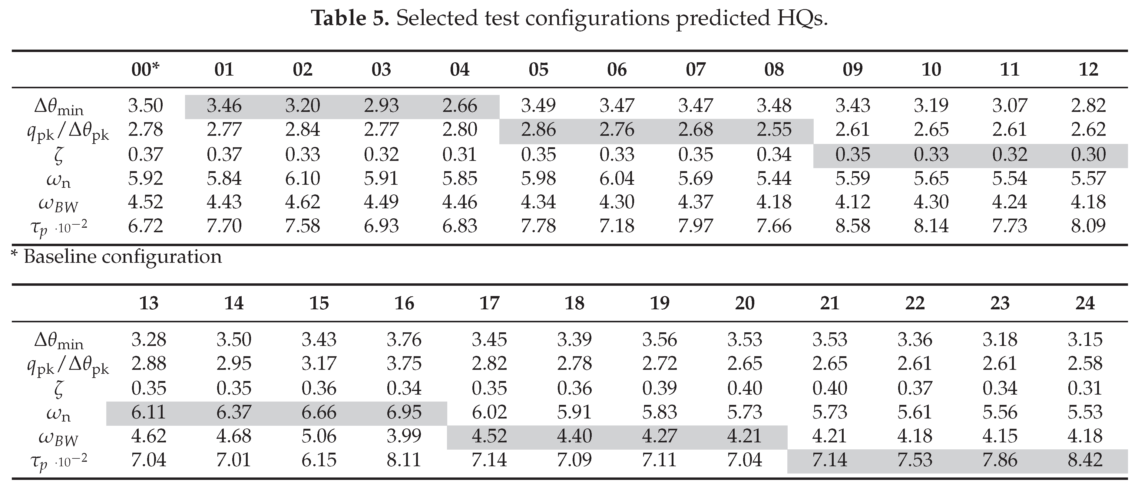
Each group of four points is equally spaced and minimize the distance from the mean value of the other index7 pertaining to the same pHQ. In this way, we expect each configuration to show the variability trends only for the considered QoI, with limited interference from the secondary one. Table 5 provides a complete picture of the 24 defined configurations in terms of pHQ.
5.2. Normal Flight Envelope Results
Figure 17 presents the results for the HQs in the 24 configurations, for each of the performance listed in the Table 3. First, it must be noted that the reference configuration is not able to ensure Level 1 HQ due to the inability to stay within the desired limits for altitude. A more extensive look at Table 3 reveals that the altitude is the performance that is the most affected by the uncertainty of the FSM. The analysis of the results reveals that the most critical performance standard —– and the most sensitive to uncertainty in the pHQs —– is the altitude. Figure 17 shows that the eVTOL gains significant altitude during the FTM. At the start of the deceleration phase, the controller commands a sharp pitch-up manoeuvre to initiate braking. Due to the high aggressiveness of the command and the sustained forward speed at which the deceleration begins, the aircraft responds with a rapid climb. A similar effect occurs during acceleration, where the eVTOL loses altitude. However, since this phase starts from a hover, the impact is less marked.
In terms of lateral-directional performance, the vehicle comfortably achieves the desired level, with lateral track deviations and heading excursions remaining around the order of throughout all simulations. This outcome directly reflects the findings of roll-due-to-pitch coupling, which confirmed the absence of coupling when the aircraft is operated in a purely longitudinal manner. The numeric results have not been reported in the Table 3 given their low relevance.
Regarding the longitudinal requirement, although the aircraft can maintain a stable hover for the expected duration, configuration uncertainties can result in minor deviations from the desired region.
The analysis highlights two main outcomes:
- Firstly, aside from the altitude requirement, the FTM can generally be completed at the desired level when flying in the NFE (i.e. in the absence of external disturbances). This is primarily due to the effectiveness of the FCS, which is capable — even under high attack rates — of keeping the eVTOL within the required boundaries, especially along the lateral-directional axes.
- Secondly, despite the positive contribution of the FCS to the closed-loop response of the aircraft, the uncertainty in the pHQs still has a significant impact on the overall FTM performance. Although no consistent trend emerges between the worse pHQ simulations and worse aHQ obtained, small variations in the tested configurations can easily push the eVTOL to different levels of performance threshold. It must be noted, that it was not possible to select configurations where only a single pHQ characteristic was modified keeping all the others constant.
Overall, it is possible to say that parameter sets in the range of uncertainty that lead to worse pHQs, also show significant effect on the aHQ behaviour. So, the idea of performing the uncertainty assessment at the level of pHQ, using much simpler open-loop tests, represents a good approach for the identification of the most critical FSM. The results suggest that the level of uncertainty in the input models is large and consequently the impact on the aHQ is significant. So, it is possible to conclude that a lower uncertainty in the FSM input parameter will be necessary to employ only the nominal model in the aHQ simulations with confidence.
5.3. Atmospheric Disturbances Flight Test Results
The FTM operations are now extended to include the effect of atmospheric disturbances, entering is an area of the flight envelope where the credibility of the FSM becomes crucial to assess HQ results. To analyse the VTOL behaviour under external disturbances, a wind turbulence model is introduced.
The method adopted here follows MIL-F-8785C (Reference [29]), which states that the "engineering model may be considered as the simplest model which is consistent with any related usage in aircraft design, but still correctly identifies the primary parameters of particular interest". Accordingly, the Von Kármán spectral model is used. The model defines the power spectral density for the three turbulent velocity components - taking white noise as input - and the turbulent roll angular rate spectrum; pitch and yaw rates are derived subsequently from the velocity components.
In addition to random fluctuations, a mean wind component dependent only on altitude is applied. Two mean wind velocities 8, 0.5 and 1 m/s, are analysed, each combined with three wind directions (). Since the FTM operates at low altitude, the Integral Length Scales and the Turbulence Intensities depend only on altitude, as per MIL-F-8785C [29].
To eliminate any bias associated with the stochastic nature of turbulence, a preliminary set of 40 runs is performed using the nominal aircraft configuration. . For each turbulent component (u, v, w, p), 10 simulations are run, varying only that component while keeping the others constant. The random seed yielding the worst performance is selected for each component. This procedure is repeated for every wind speed and direction choosing the worst-case performance for each wind condition. The selected seed vectors are then used consistently across the 24 test configurations, as defined in Table 5, leading to the results summarized in Figure 18.
The performance parameters deviations due model input uncertainties are significantly amplified in the presence of disturbances. The aircraft is no longer able to consistently meet the longitudinal requirement. Furthermore, during the hover phase, substantial deviations are observed from the intended arrival point (top-left plot in Figure 18), mainly due to wind effects during hover and the use of the multicopter controller’s position mode. Enhancing position control during this phase may help maintain compliance with the requirement, allowing the aircraft to hold its intended arrival point.
An interesting aspect is furthermore represented by the tailwind case, i.e. deg, as in general it reveals to be the only wind condition in which the FTM acceleration-deceleration phase generally satisfies the desired lateral, vertical, and heading requirements. However, 8 configurations with tailwind conditions result in divergent simulations. In these cases the eVTOL struggles to maintain stable hover in the final phase, when the tailwind excites a divergent pitch oscillation that ultimately leads to complete loss of control. This behaviour will need to be investigated further in the future.
Heading performance also suffers a marked degradation, with the eVTOL exhibiting large deviations once the deceleration is commanded. This effect is primarily driven by the p-rate turbulence component, which, combined with lateral velocity v, strongly couples with the pitch and yaw axes. As a result, the aircraft frequently exceeds adequate boundaries, especially under headwind and crosswind conditions. Figure 18 highlights how this issue becomes more prominent near the end of the deceleration phase, when the aircraft reaches its maximum pitch angle.
Similarly, altitude performance drops to the controllable level, with headwind conditions proving particularly critical (as shown in Figure 19). The longitudinal turbulence component intensifies the aggressiveness of the deceleration phase, causing the vehicle to exceed desired thresholds. In contrast, lateral performance is comparatively less affected, as the FCS still manages to track the test course within the desired standards.
In summary, these analyses highlight that the effects of wind disturbances can be assessed using these simulations. Trends with wind intensity and direction are identifiable using the nominal FSM. These trends are reproduced similarly by the modified configurations, excluding some cases. However, it must be remembered that the uncertainty levels considered have been assessed as large in the previous section.
6. Maximum Unnoticeable Added Dynamics
MUAD boundaries are defined as the alterations in aircraft dynamics that can be introduced in the aircraft without the pilot consciously perceiving them. The approach proposed in the introduction says that if the envelope of the uncertain transfer functions pertaining to the ACR under consideration multiplied by the selected falls within the limits of the MUAD, then the nominal model could be considered credible and used to perform ACR evaluations with flight simulators. In this case, we will make the hypothesis that the minimal acceptable CR is equal to 1 (see [6] for more details on it). In contrast, if the uncertainty ranges encompassing the nominal results exceed the MUAD boundaries, credibility should not be considered appropriate. So, the applicant will need to reduce the uncertainty or assess the impact of uncertainty on the simulations.
The envelopes (summarised in Table 6) are valid across the frequency range from to rad/s and exhibit a "hourglass" shape, narrowing around 3 rad/s, which is the frequency region most relevant to manual control [30].
In light of this, MC generated FSM can be employed to assess the influence has on the aircraft transfer function (TF), computing the envelope of uncertain TFs (eTFs) and comparing them with the nominal one. In performing this assessment, it must be clearly taken into account that the MUAD boundaries were originally conceived for a class of aircraft very different from eVTOLs and may therefore present limitations in their applicability. Nevertheless, they are used in this work to demonstrate the approach which enhances FSM credibility.
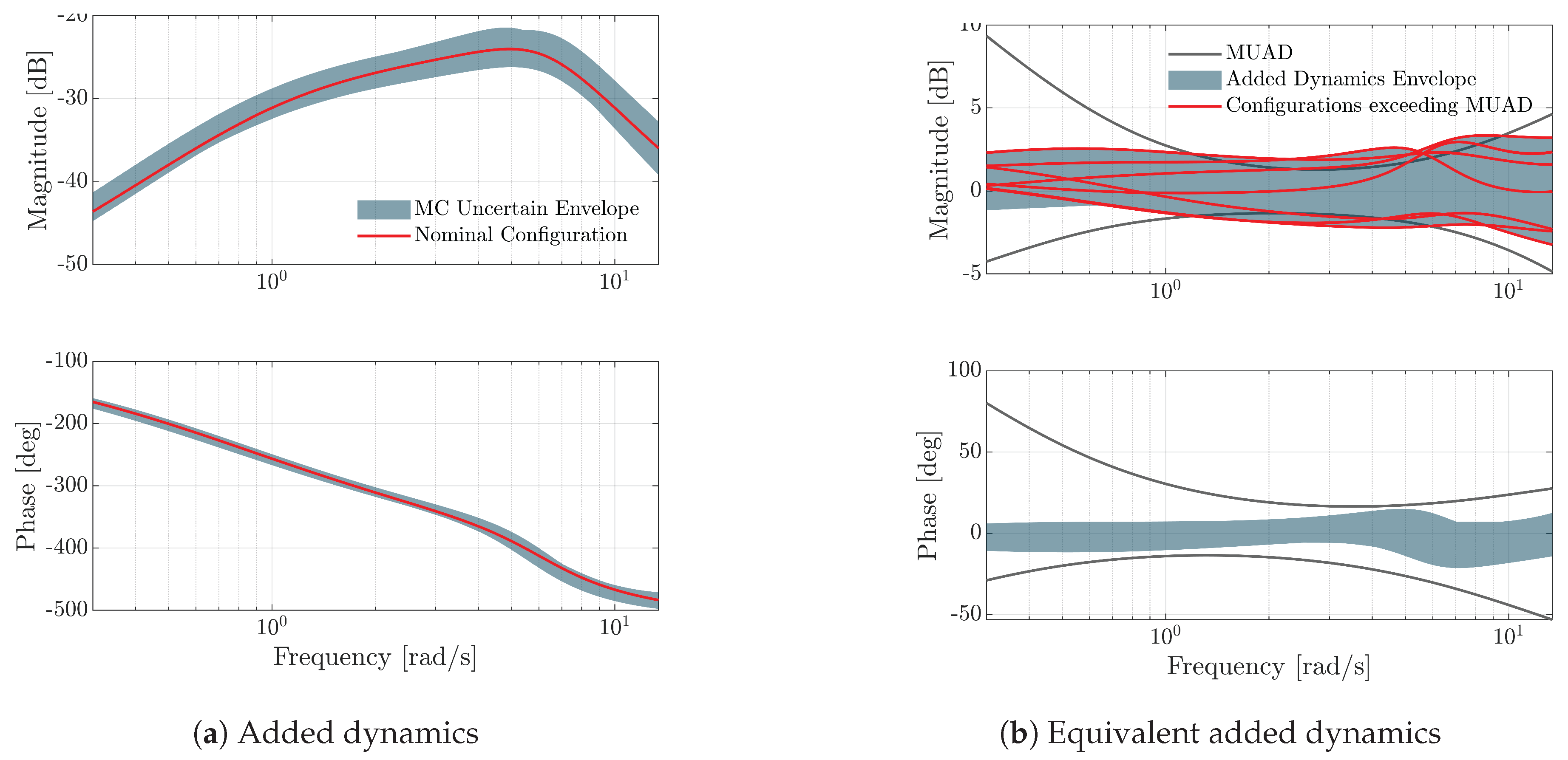
In Figure 20 below, the main outcome of this assessment is shown. The nominal system Bode plots are displayed together with their uncertain region (Figure 20(a)) — derived using the MC results of the UA phase — and the corresponding "added-dynamics interpretation" is given (Figure 20(b)). The difference between the 500 MC output eTFs and the reference TF is interpreted as an unmodelled dynamics, showing that the uncertainty leading to the eTFs is bounded by MUAD limits for all the relevant frequencies (0.3-12 rad/s), except for some limited excursion outside magnitude boundaries slightly above 6 rad/s. Consequently, it can be fairly assumed that the FTM results obtained using the baseline configuration of the FSM would lead to the same HQ ratings as for the worst or best configuration in the uncertainty range, at least for the performance that depend on this transfer function.: according to the proposed approach, these results are indeed consistent with the performances achieved in the NFE. The differences between the 24 tested configurations are not such as to drive the eTF out of the MUAD envelopes for this TF.
Following a similar line of reasoning, the previous altitude performance results can be interpreted in MUAD terms. The FTM simulation phase highlighted indeed an increased altitude gain in the VTOL’s response, revealing a strong coupling between the longitudinal and vertical axes in the assigned dimension of HQs. Therefore, it is necessary to investigate whether this behaviour may be attributed to the shape of the added dynamics related to input uncertainties. To explore this aspect, the eTFs between the longitudinal input command and the resulting vertical velocity response 9 are defined and the corresponding added dynamics are assessed.
Although the eTFs remains fully enclosed within the MUAD envelopes for the phase angles, the TFs of several configurations exceed the magnitude boundaries, especially in the central region of the frequency range, where the system is expected to be more sensitive to such dynamics. The increased spread of the wTFs correlates with the degradation of altitude performance, resulting in a high degree of FTM performance variability, as seen in Figure 17. What must be noted is the fact that not all the most critical configurations identified in Section 5.2 showed a TF outside the MUAD range, highlighting the importance of considering a sufficiently complete set of pHQs in the UQ phase of the investigation.
Figure 21.
MUAD analysis on transfer function, for the 24 aircraft configurations considered
Once this first assessment has been carried out, the sensitivity of the FSM to added dynamics across the frequency range can be studied, selectively assessing the validity of original MUAD boundaries on its dynamics. This process, which has been widely studied in the literature (see Refs. [31,32,33]) requires to investigate the aircraft response to several added dynamics, specifically tailored to modify the baseline transfer function at several frequency values. This allows exploring the pilot control sensitivity and adaptation in terms of HQ rating. The simplest approach to perturb the transfer function is to model the added dynamics either as first-order lag-lead and lead-lag dynamics, as in Ref. [32], or through second-order in the form of dipoles [31,33]
This work employs the second-order form, as it allows to intuitively control the frequency position of the disturbance and gradually increase/decrease the corresponding amplitude. To preserve the shape of within the control loop, the dipole is placed in series with the controller’s velocity setpoint . Following the approach discussed in Ref. [33], the dipole central frequency value was relocated iteratively between 1 and 6 rad/s (Figure 20(b)) while was gradually increased from 0.25 to 0.70. The damping ratio of the denominator was always fixed at . Figure 22 shows an example of the adopted approach, for both the added dynamics and the resulting effect on the baseline TF.
To plan the FTM simulations, three configurations were analysed: the case of NFE operations ( m/s) and the cases of headwind (), for both m/s and m/s. Figure 23 collects the results for altitude performance, which is the most sensitive to variations in . For all of the tested operating conditions, a clear dependency upon the dipole’s location exists. while in the high part of the frequency range ( rad/s) effect is not driving the rating out of the baseline level, at lower frequencies (in the range 1.5-3 rad/s) the results show the greatest variability, eventually bringing the system outside the adequate boundary. It can also be observed that, while at high frequencies the trend of the performance decreases monotonically with increasing the frequency of and increases monotonically with the intensity of the added disturbance (i.e. with ), at low frequencies this monotonicity is lost.
This behaviour can be attributed to two main factors. The first reason can be sought in the effect exerts on . When a high- low-frequency dynamics is inserted within the control loop, the dynamics of the aircraft is affected to such an extent that the velocity command is inhibited. As a result, the aircraft cannot longer adequately follow the input imposed by the controller, leading to oscillations in both the input and the response that disrupt the FTM. In this context, the observed improvement, visible at 1 and 2 rad/s in Figure 23, should not be interpreted as a beneficial effect of the added dynamics, but rather as a consequence of the piloting algorithm’s inability to correctly execute the manoeuvre, ultimately making the results unreliable. Specifically, during the acceleration phase, the eVTOL reaches the required maximum forward speed much more slowly than in the nominal case, drastically reducing the level of aggressiveness needed for the manoeuvre and both the deceleration aggressiveness and the associated altitude gain. So, the improvement in altitude performance does not correspond to an overall improvement of the FTM performance.
A second interpretation can be sought in the nature of the HQ requirement assigned to the aircraft, as the required FTM input does not contain any high-frequency component and is likely to be mostly affected by dipoles located in the lower part of the frequency range. A different task (e.g. a pitch-tracking task for the measurement of control effort, as done in [33]) may result in a different frequency-related behaviour.
It is interesting to note that, as the vary and, specifically, as the bandwidth parameter decreases (i.e., approaching the threshold between Level 1 and Level 2 of ADS-33), the degradation in the pHQs, now directly controlled by means of the added TF — rather than indirectly influenced via different aircraft configurations — directly translates into a deterioration in the corresponding assigned HQs, making the relationship between the two HQs dimensions clearer.
In summary, this analysis showed that taking the envelope of uncertain models in the frequency domain and comparing it with MUAD limits may be a good way to verify if the uncertainties are able to generate modification that can affect or not the aHQ performance. However, it is important to consider uncertainties that affect a complete set of pHQ and compare all direct and cross transfer functions that affect the FTM with the MUAD limits.
7. Conclusions
This paper successfully proposed and demonstrated a methodology for assessing the credibility of flight simulation models for VTOL handling qualities certification by simulation. The key results obtained are:
- The impact of FSM input parameter uncertainties was effectively propagated through sensitivity analysis (MOAT, VBD) to quantify variations in open-loop predicted HQs and, subsequently, in the aircraft’s envelope of transfer functions.
- A novel application of the Maximum Unnoticeable Added Dynamics concept was introduced: by comparing the envelope of uncertain TFs, scaled by a confidence ratio, against MUAD boundaries, a quantitative criterion for FSM credibility for specific HQ-related tasks was established.
For the studied lift+cruise VTOL model and the deceleration to hover flight test manoeuvre the eTFs for longitudinal control dynamics largely satisfied the MUAD limits across the uncertain configurations, suggesting the nominal FSM’s credibility for assessing performance aspects primarily driven by these dynamics. However, the eTFs for vertical axis dynamics coupled with longitudinal inputs for several uncertain configurations exceeded MUAD magnitude limits. This finding correlated well with the observed variability and degradation in FTM altitude-keeping performance, indicating that FSM uncertainty in these coupled dynamics could lead to non-credible predictions for altitude-critical tasks if the nominal model alone were used.
The deliberate introduction of added dynamics in the form of dipoles further confirmed the frequency-dependent sensitivity of FTM performance, particularly altitude control, to deviations from the nominal aircraft dynamics.
These findings are highly promising for the advancement of a standardized certification by simulation approach for VTOL aircraft. The MUAD-based framework offers an objective, engineering-driven method to link FSM fidelity directly to pilot-perceptible dynamic changes. This is a significant step towards reducing reliance on extensive and potentially hazardous flight testing, especially when evaluating off-nominal conditions or the impact of model uncertainties. By demonstrating that an FSM’s predictions remain within "unnoticeable" dynamic boundaries despite its own uncertainties, confidence in its use for certification can be substantially increased.
However, to fully mature this approach into a standardized practice, further investigation is crucial in several areas:
- VTOL-Specific MUAD Boundaries. The existing MUAD boundaries were originally conceived for conventional aircraft. Research is needed to tailor, refine, and validate these boundaries for the diverse range of VTOL configurations (e.g., lift+cruise, multicopter, tiltrotor) and their unique critical flight tasks and control strategies.
- Comprehensive Transfer Function Assessment, While this study focused on key longitudinal and coupled vertical dynamics, a standardized approach would require a systematic assessment of all relevant direct and cross-coupling transfer functions that significantly influence critical FTM performance against MUAD limits.
Addressing these areas will solidify the proposed CbS methodology, paving the way for more efficient, cost-effective, and robust certification pathways for the rapidly evolving VTOL aircraft sector.
Author Contributions
Conceptualisation, G.Q. and A.R.; methodology, G.Q., A.R. and L.F.; analysis and validation, L.F., and A.R.; resources, G.Q.; data curation, A.R.; writing—introduction, G.Q. and A.R.; writing—original draft preparation, L.F. and A.R.; writing—review and editing, G.Q., A.R.; visualisation, L.F. All authors have read and agreed to the published version of the manuscript.
Funding
The work in this study done by Agata Rylko was carried out within the 38th cycle of doctoral study in aerospace engineering, in the research field "Policymaking for Urban Air Mobility acceptance" and received funding from PIANO NAZIONALE DI RIPRESA E RESILIENZA (PNRR). The work in this study done by Giuseppe Quaranta and Lorenzo Favaro was carried out within MOST -– Sustainable Mobility National Research Center and received funding from the European Union Next-Generation EU (PIANO NAZIONALE DI RIPRESA E RESILIENZA (PNRR) – MISSIONE 4 COMPONENTE 2, INVESTIMENTO 1.4 – D.D. 1033 17/06/2022, CN00000023). This manuscript reflects only the authors’ views and opinions, neither the European Union nor the European Commission can be considered responsible for them.
Acknowledgments
The authors would like to acknowledge Hamdy Sallam as the source of inspiration for Figure 1. In addition, the authors would like to acknowledge the support of Prof. Marco Lovera and the ADSL Lab. of the Department of Aerospace Science and Technology to provide data and models related to the drone eVTOL tested in this paper.
Conflicts of Interest
The authors declare no conflicts of interest.
| 1 | See for instance the European Union Commission implementing regulation (EU) 2024/1111 of 10 April 2024 which deals with the establishment of requirements for the operation of manned aircraft with a vertical take-off and landing capability |
| 2 | This document is often colloquially identified as ’ADS-33’ making reference to the original design standard from which it originates [25]. |
| 3 | |
| 4 |
is modelled as a gain on the airspeed information fed by the FSM sensor unit to the thrust-related LUT, to not influence thrust dependence on throttle command. |
| 5 |
Figure 13 has been derived from a m/s, resulting in deg; up to deg. |
| 6 | The NFE "corresponds to the normal use of the VTOL aircraft according to its Concept of Operations" [4]. |
| 7 | This is true except for . Due to the skewed shape of the MC distribution, to consider its worst-case values, it has been necessary to make a different choice. |
| 8 | Evaluated at 6 m altitude and adjusted according to the FTM altitude considering wind shear. |
| 9 |
analysis yields analogous results, preserving the shape of Figure 21(b) added dynamics envelope. |
References
- Anon.. Third Publication of Means of Compliance with Special Condition VTOL, MOC-3 SC-VTOL Issue 2. Cologne, Germany, 2023. EASA.
- Anon.. SC-VTOL, Special Condition for small-category VTOL aircraft, Issue 1, 2019. EASA.
- Cooper, G.E.; Harper, R.P. The use of pilot rating in the evaluation of aircraft handling qualities. Technical Report TN D-5153, National Aeronautics and Space Administration, 1969.
- Anon.. ED-295, Guidance on VTOL Flight Control Handling Qualities Verification, 2024. EUROCAE.
- Anon.. MIL-DTL-32742(AR), Department of Defense Detail Specification Handling Qualities for Military Rotorcraft. Redstone Arsenal, Alabama, 2023.
- Padfield, G.; van’t Hoff, S.; Hofmeister, P.; Lu, L.; White, M.; Quaranta, G. Rotorcraft Certification by Simulation and Analysis. An Introduction to the Principles and Practices; Springer, 2025. [CrossRef]
- Bianco-Mengotti, R.; Ragazzi, A.; Del Grande, F.; Cito, G.; Brusa Zappellini, A. AW189 Engine-Off-Landing Certification by Simulation. In Proceedings of the AHS 72nd Annual Forum, West Palm Beach, FL, 2016.
- Ragazzi, A.; Bianco Mengotti, R.; Sabato, P.; Afruni, G.; Hyder, C. AW169 loss of tail rotor effectiveness simulation. In Proceedings of the European Rotorcraft Forum, Milano, Italy, 2017.
- Wilson, D.; Riley, D. Cooper–Harper pilot rating variability. In Proceedings of the AIAA 16th Atmospheric Flight Mechanics Conference, 1989, pp. 89–3358 CP. [CrossRef]
- Anon. Flying Qualities of Piloted Aircraft. Technical Report MIL-STD-1797A, US Department of Defense Interface Standard, 1990.
- Martinelli, E. Modelling, control, integration and testing of an eVTOL drone. Master’s thesis, Politecnico di Milano, Italy, 2022.
- Bara, K. Aerodynamics, propulsion and testing of an eVTOL drone. Master’s thesis, Politecnico di Milano, Italy, 2023.
- Rylko, A.; Lovera, M.; Quaranta, G. Aerodynamic Model Development and Fidelity Assessment for eVTOL Predicted Handling Qualities. In Proceedings of the 50th European Rotorcraft Forum (ERF 2024), Marseille, France, 2024; pp. 1–14.
- Tobias, E.L.; Tischler, M.B. A model stitching architecture for continuous full flight-envelope simulation of fixed-wing aircraft and rotorcraft from discrete-point linear models. Technical Report Special Report RDMR-AF-16-01, US Army AMRDEC, 2016.
- Nabi, H.N.; Visser, C.C.d.; Pavel, M.D.; Quaranta, G. Development of a quasi-linear parameter varying model for a tiltrotor aircraft. CEAS Aeronautical Journal 2021, 12, 879–894.
- Martello, N.C. Modelling and integration of an eVTOL UAV. Master’s thesis, Master Thesis, Politecnico di Milano, Italy, 2021.
- Rylko, A.; Quaranta, G.; M., L. Aerodynamic Model Development and Fidelity Assessment for eVTOL Predicted Handling Qualities. In Proceedings of the 50th European Rotorcraft Forum, September 2024.
- Dalbey, K.; Eldred, M.; Geraci, G.; Jakeman, J.; Maupin, K.; Monschke, J.; Seidl, D.; Swiler, L.; Tran, A.; Menhorn, F.; et al. Dakota, A Multilevel Parallel Object-Oriented Framework for Design Optimization, Parameter Estimation, Uncertainty Quantification, and Sensitivity Analysis: Version 6.14 Theory Manual. Sandia National Laboratories, Albuquerque, NM, 2021.
- Gentle, J.E. Random number generation and Monte Carlo methods; Vol. 381, Springer, 2003.
- Saltelli, A.; Ratto, M.; Andres, T.; Campolongo, F.; Cariboni, J.; Gatelli, D.; Saisana, M.; Tarantola, S. Global Sensitivity Analysis; Wiley, 2008.
- Campolongo, F.; Saltelli, A. Sensitivity analysis of an environmental model: an application of different analysis methods. Reliability Engineering & System Safety 1997, 57, 49–69.
- Anon.. ASME V&V 20 Standard for Verification and Validation in Computational Fluid Dynamics and Heat Transfer; American Society of Mechanical Engineers: New York, NY, 2009.
- Morris, M.D. Factorial sampling plans for preliminary computational experiments. Technometrics 1991, 33, 161–174.
- Adams, B.; Bohnhoff, W.; Dalbey, K.; Ebeida, M.; Eddy, J.; Eldred, M.; Hooper, R.; Hough, P.; Hu, K.; Jakeman, J.; et al. Dakota, A Multilevel Parallel Object-Oriented Framework for Design Optimization, Parameter Estimation, Uncertainty Quantification, and Sensitivity Analysis: Version 6.16 User’s Manual. Sandia National Laboratories, Albuquerque, NM, 2022.
- Anon.. Proposed Revisions to Aeronautical Design Standard – 33E (ADS-33E-PRF) Toward ADS-33F-PRF. U.S. Army Combat Capabilities Development Command, Redstone Arsenal, AL, 2019.
- Pavel, M.; Padfielf, G. Progress in the development of complementary handling and loading metrics for ADS-33 manoeuvres. In Proceedings of the American Helicopter Society 59th Annual Forum Proceedings, May 6–8, 2003.
- Anon.. Test Guide for ADS-33E-PRF. U.S. Army Research, Development, and Engineering Command, Moffet Field, CA, 2008.
- Menberg, K.; Heo, Y.; Choudhary, R. Sensitivity analysis methods for building energy models: Comparing computational costs and extractable information. Energy and Buildings 2016, 133, 433–445. [CrossRef]
- Air Force Wright Aeronautical Laboratories, Air Force Systems Command Wright-Patterson Air Force Base, OH. Background Information and User Guide for MIL-F-878SC, Military Specification - Flying Qualities of Piloted Airplanes, 1982.
- McRuer, D.; Jex, H. A Review of Quasi-Linear Pilot Models. IEEE Transactions on Human Factors in Electronics 1967, HFE-8, 231–249. [CrossRef]
- Mitchell, D.; He, C.; Strope, K. Determination of Maximum Unnoticeable Added Dynamics. In Proceedings of the AIAA Atmospheric Flight Mechanics Conference and Exhibit, August 21–24, 2006.
- Butijn, M.; Lu, T.; Pool, D.; .; van Paassen, M. Assessment of Maximum Unnoticeable Added Lag-Lead or Lead-Lag Dynamics with a Cybernetic Approach. In Proceedings of the AIAA Scitech Forum, January 7–11, 2019.
- Matamoros, I.; Lu, T.; van Paassen, M.; Pool, D. A Cybernetic Analysis of Maximum Unnoticeable Added Dynamics for Different Baseline Controlled Systems. IFAC-PapersOnLine 2017, 50, 15847–15852. [CrossRef]
Figure 1.
SC-VTOL Subpart B Controllability and Handling Qualities concerning the different aspects of piloted flight.
Figure 1.
SC-VTOL Subpart B Controllability and Handling Qualities concerning the different aspects of piloted flight.
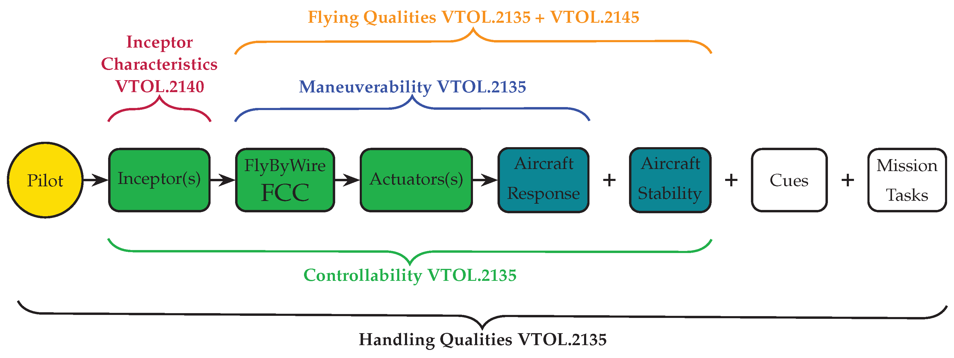
Figure 2.
Overall structure of the Certification by Simulation Process, as from [6]
Figure 2.
Overall structure of the Certification by Simulation Process, as from [6]

Figure 3.
eVTOL CAD model overview
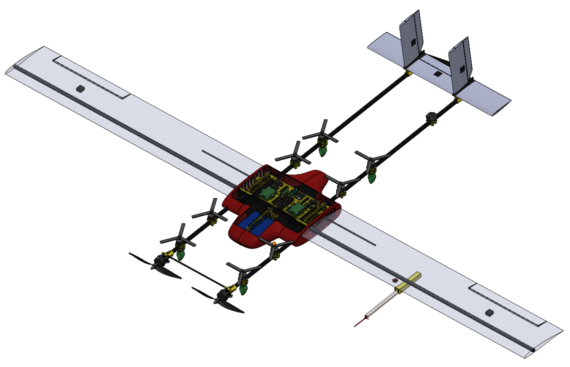
Figure 4.
Deceleration to Hover Test Course (adapted from Reference [4])
Figure 4.
Deceleration to Hover Test Course (adapted from Reference [4])
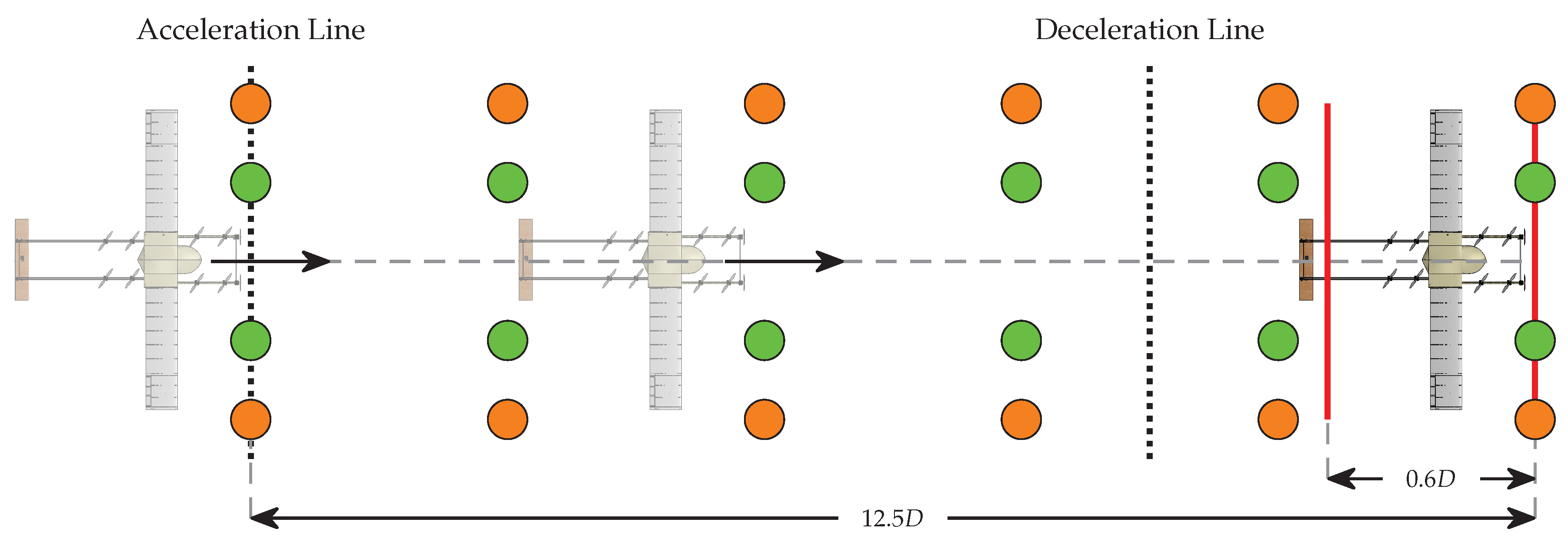
Figure 5.
Uncertainty analysis workflow
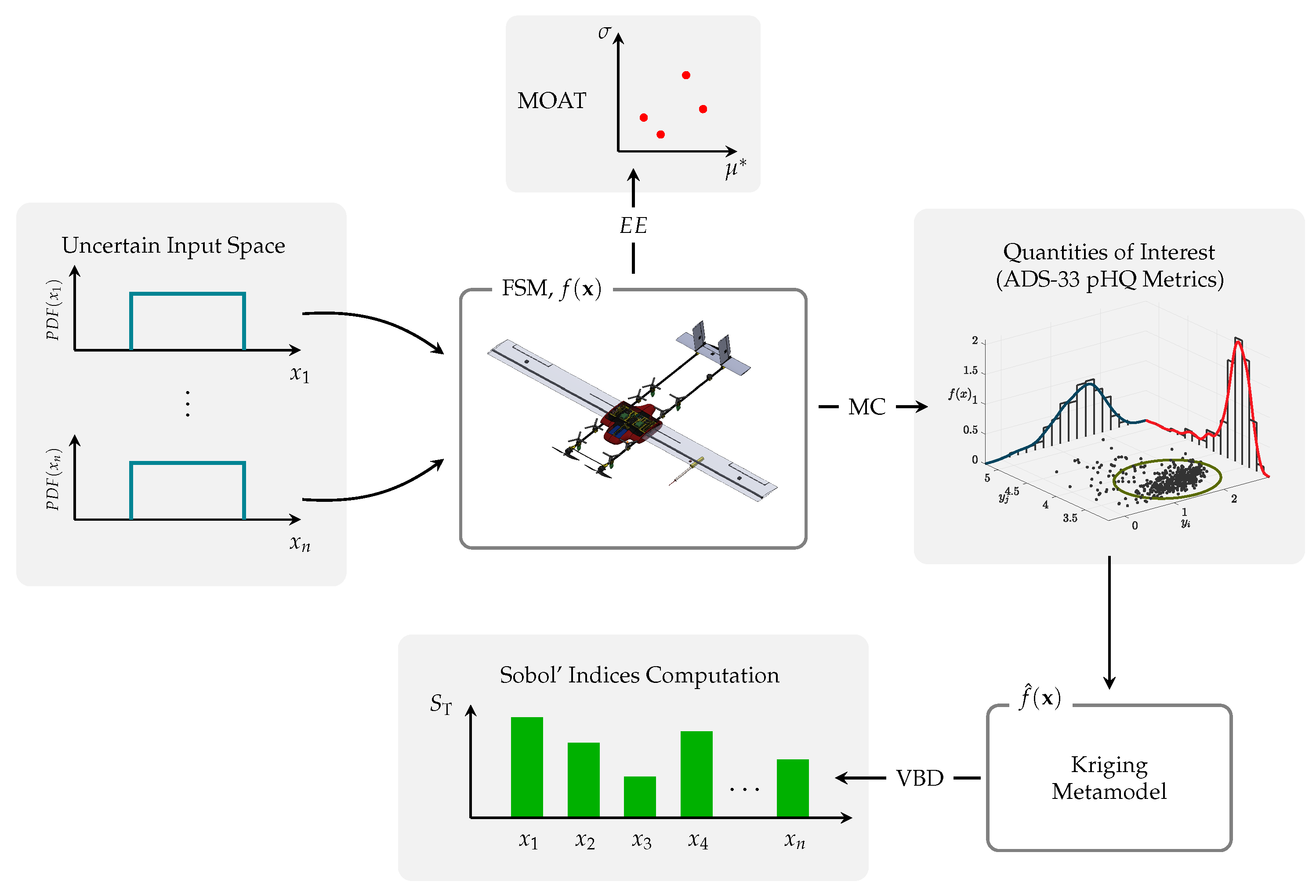
Figure 6.
Pitch attitude quickness, low-speed test manoeuvre.
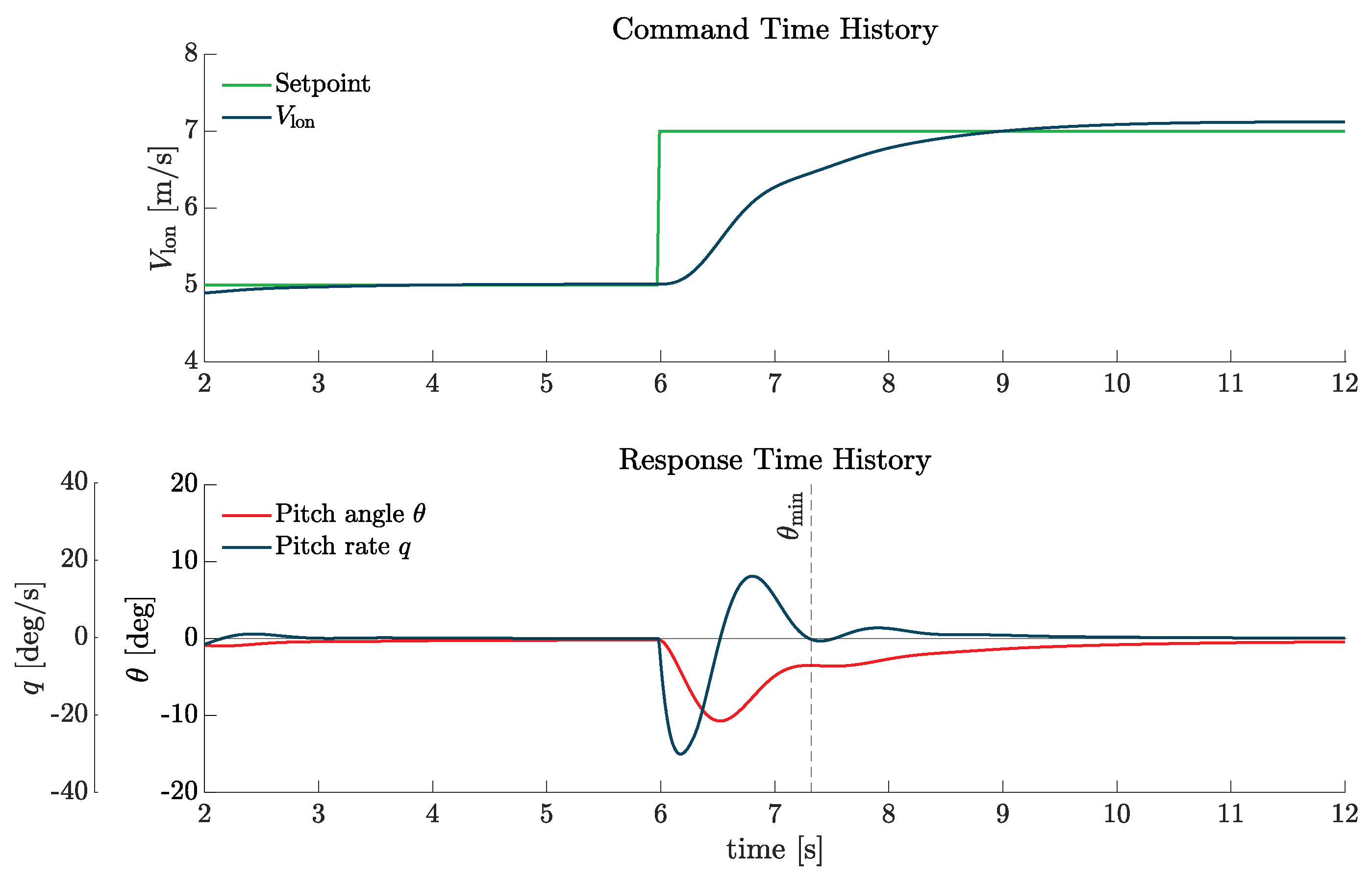
Figure 7.
Pitch attitude quickness UA results.
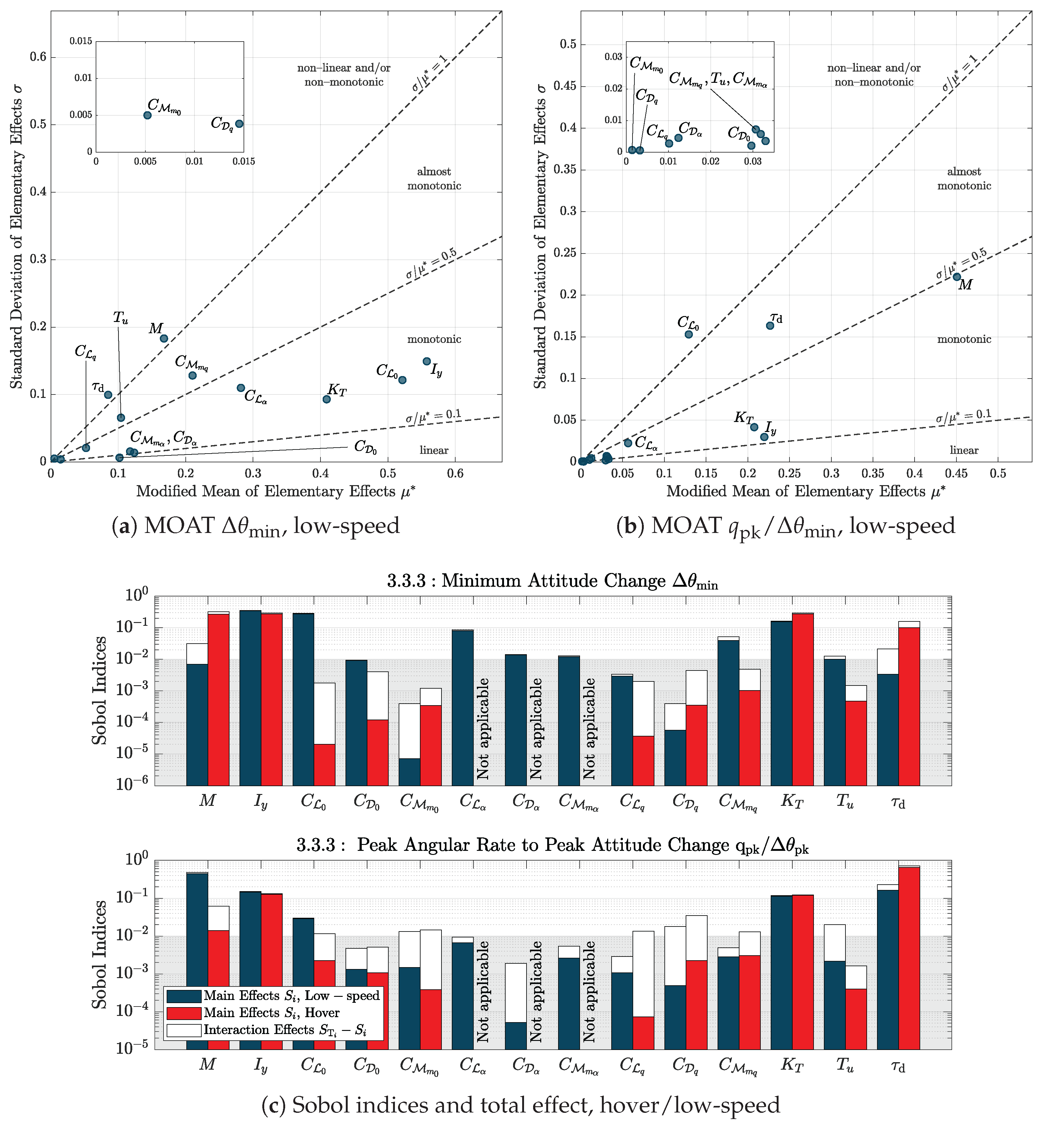
Figure 8.
Attitude quickness ADS-33 results from MC analysis
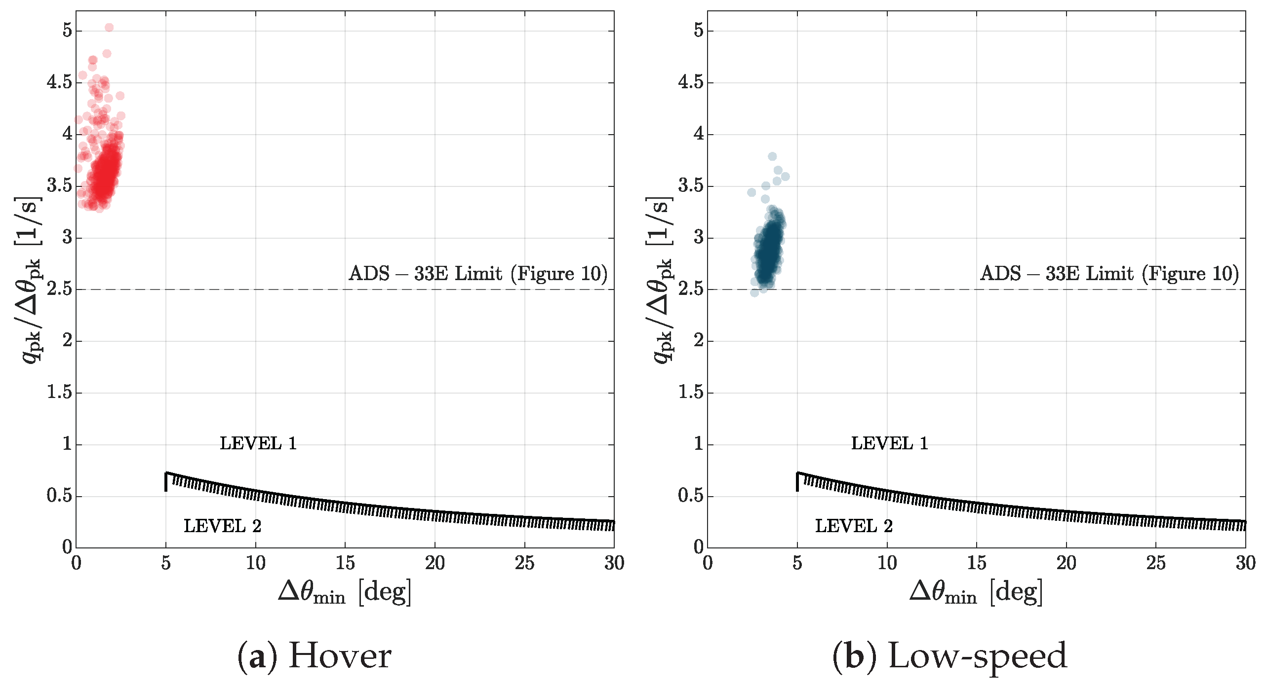
Figure 9.
Pitch dynamic stability, low-speed test manoeuvre
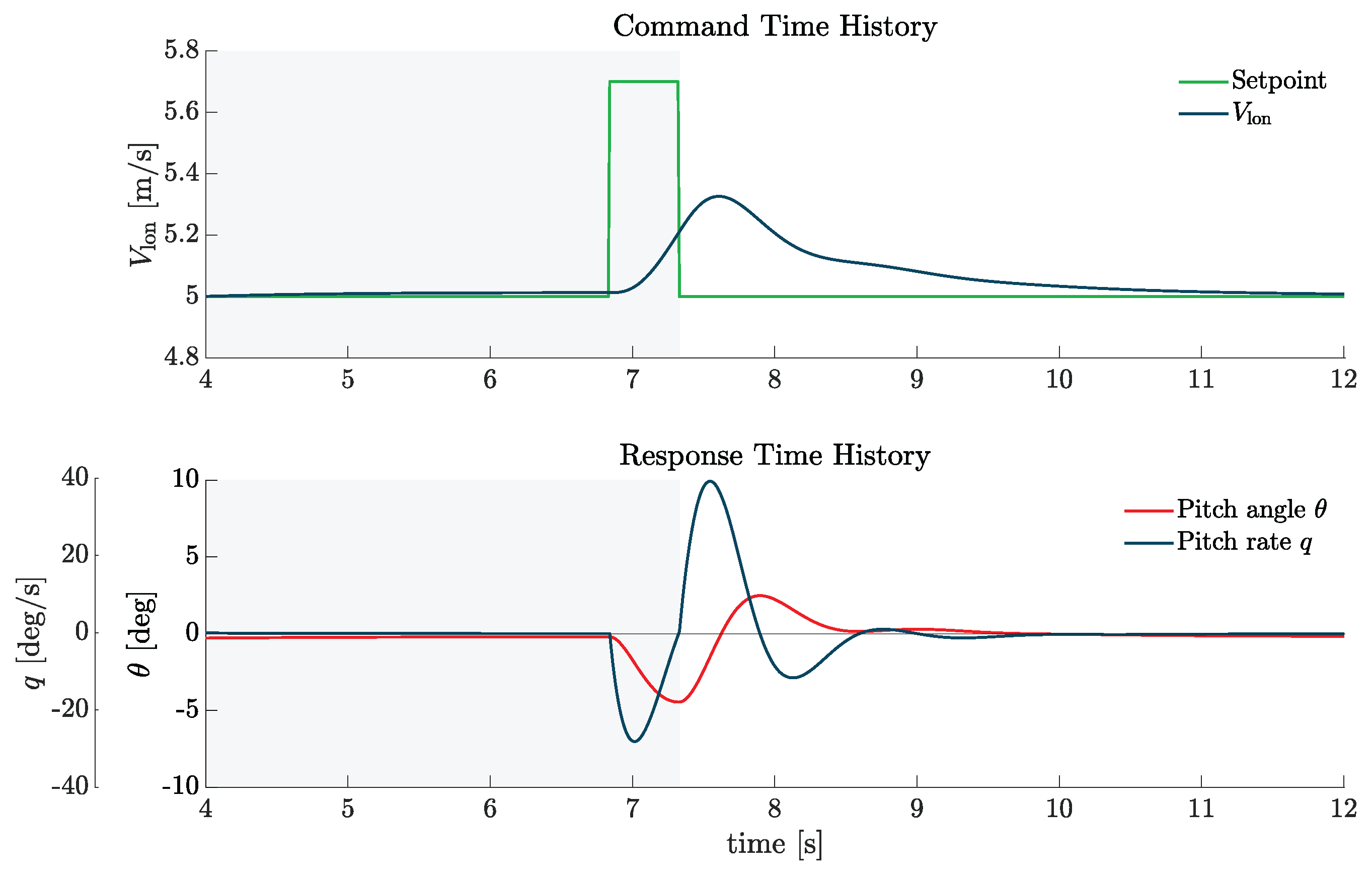
Figure 10.
Pitch dynamic stability UA results
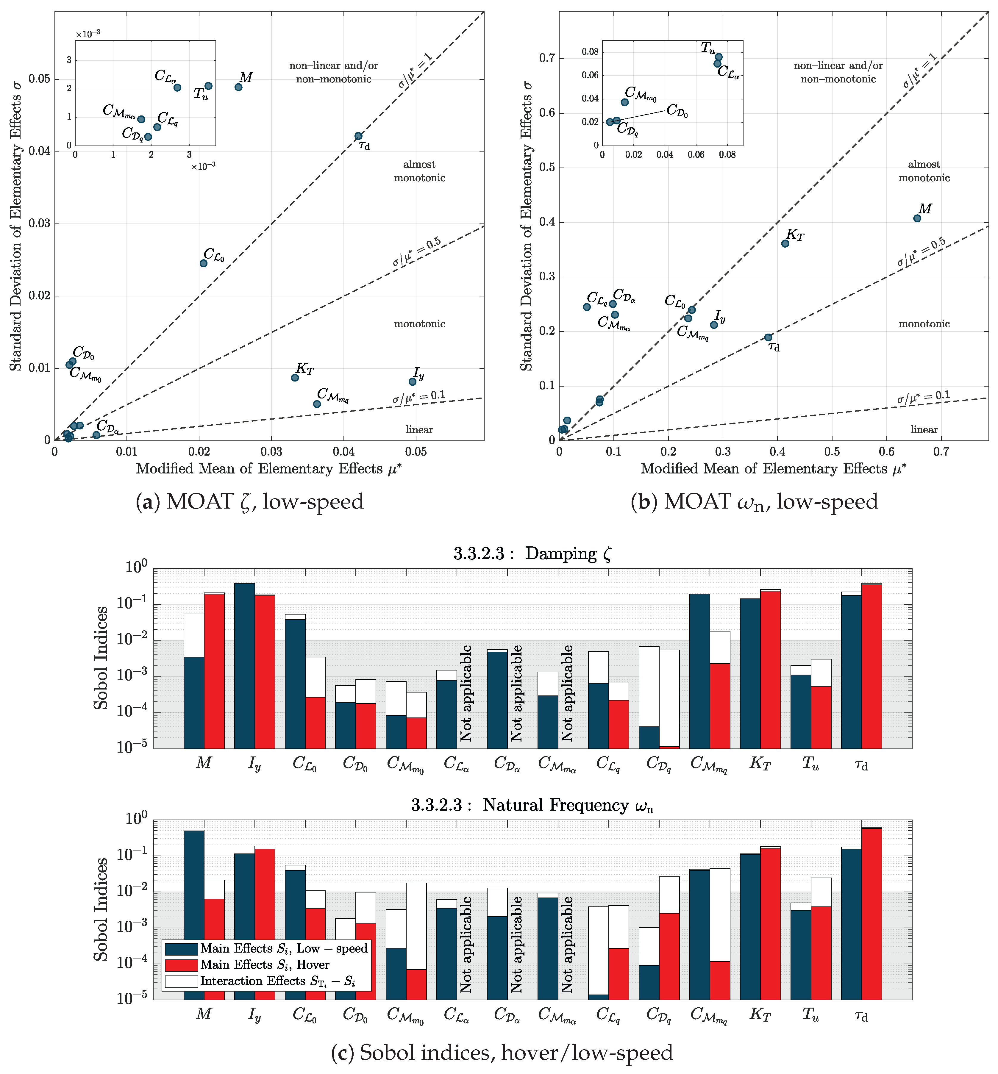
Figure 11.
Dynamic stability ADS-33 results obtained from MC analysis
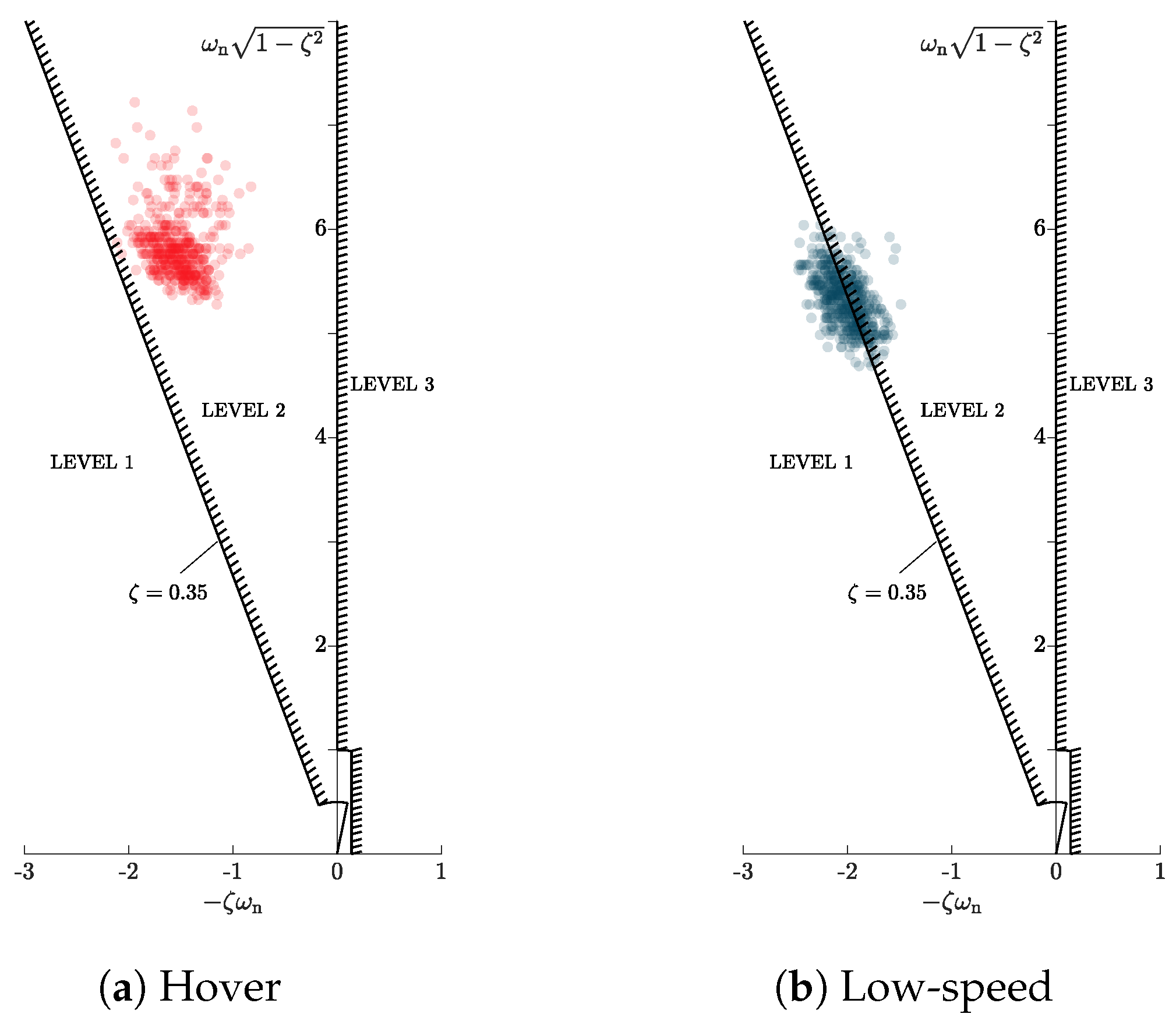
Figure 12.
Pitch bandwidth, low-speed test manoeuvre
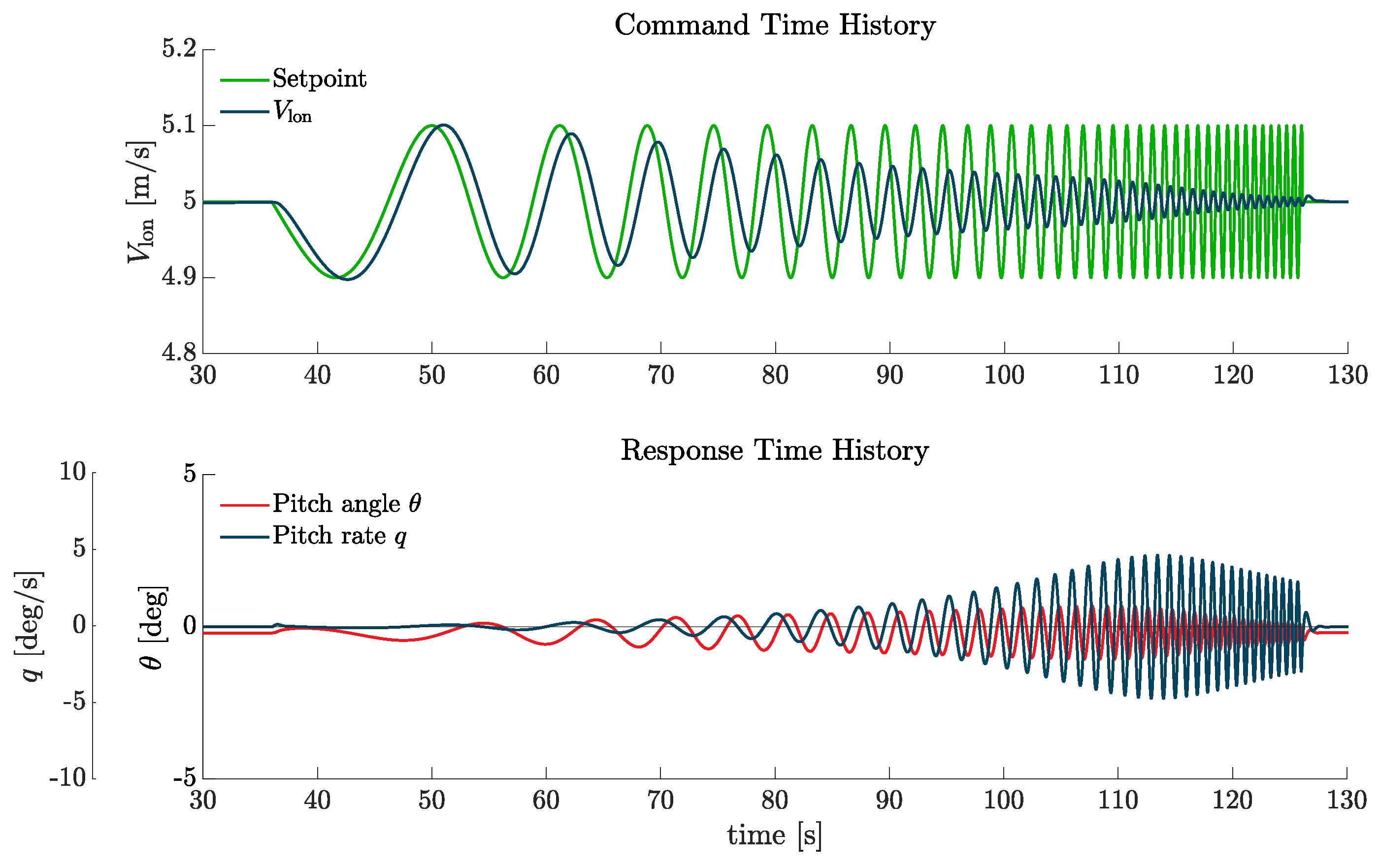
Figure 13.
Bode plots for
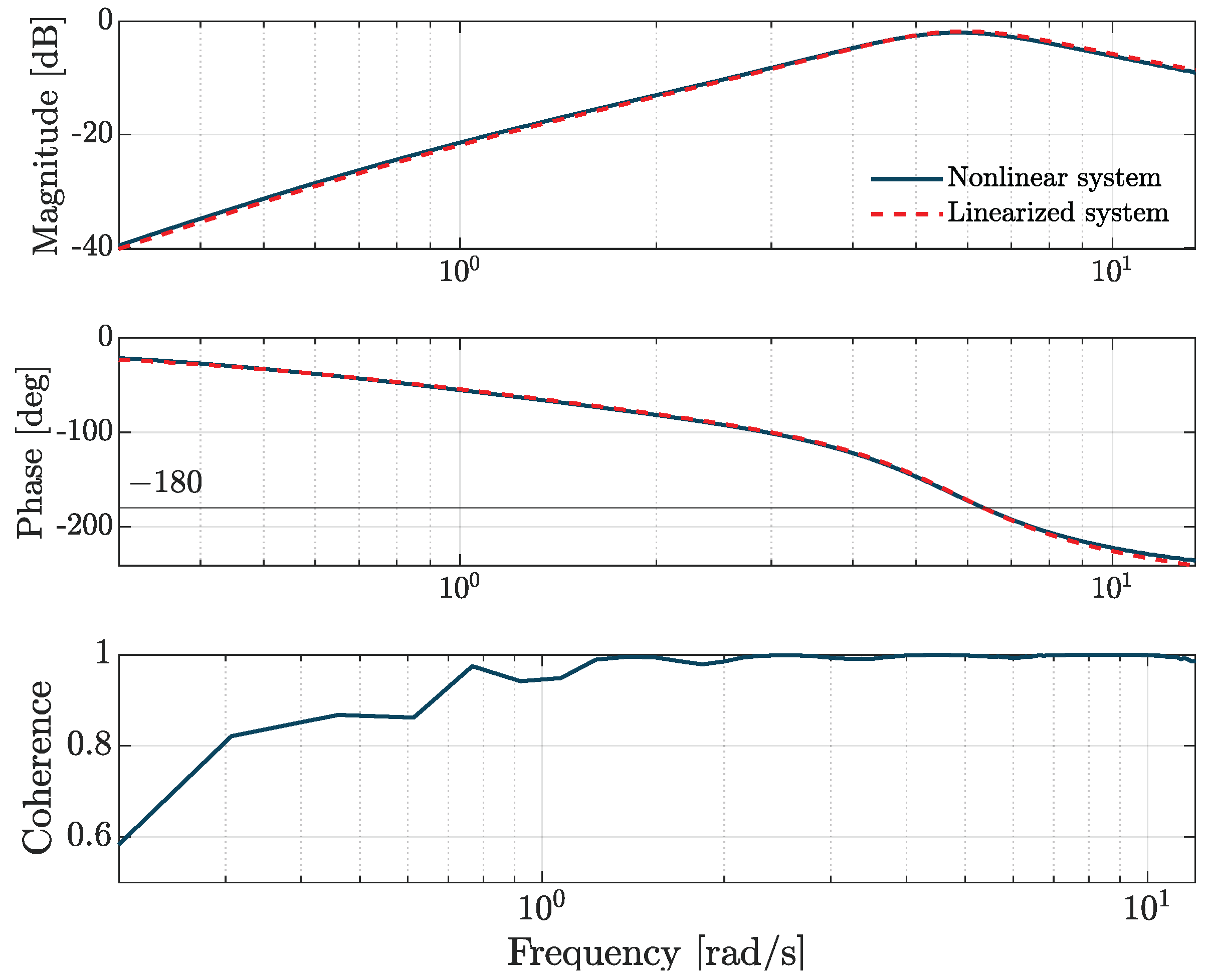
Figure 14.
Pitch bandwidth UA results
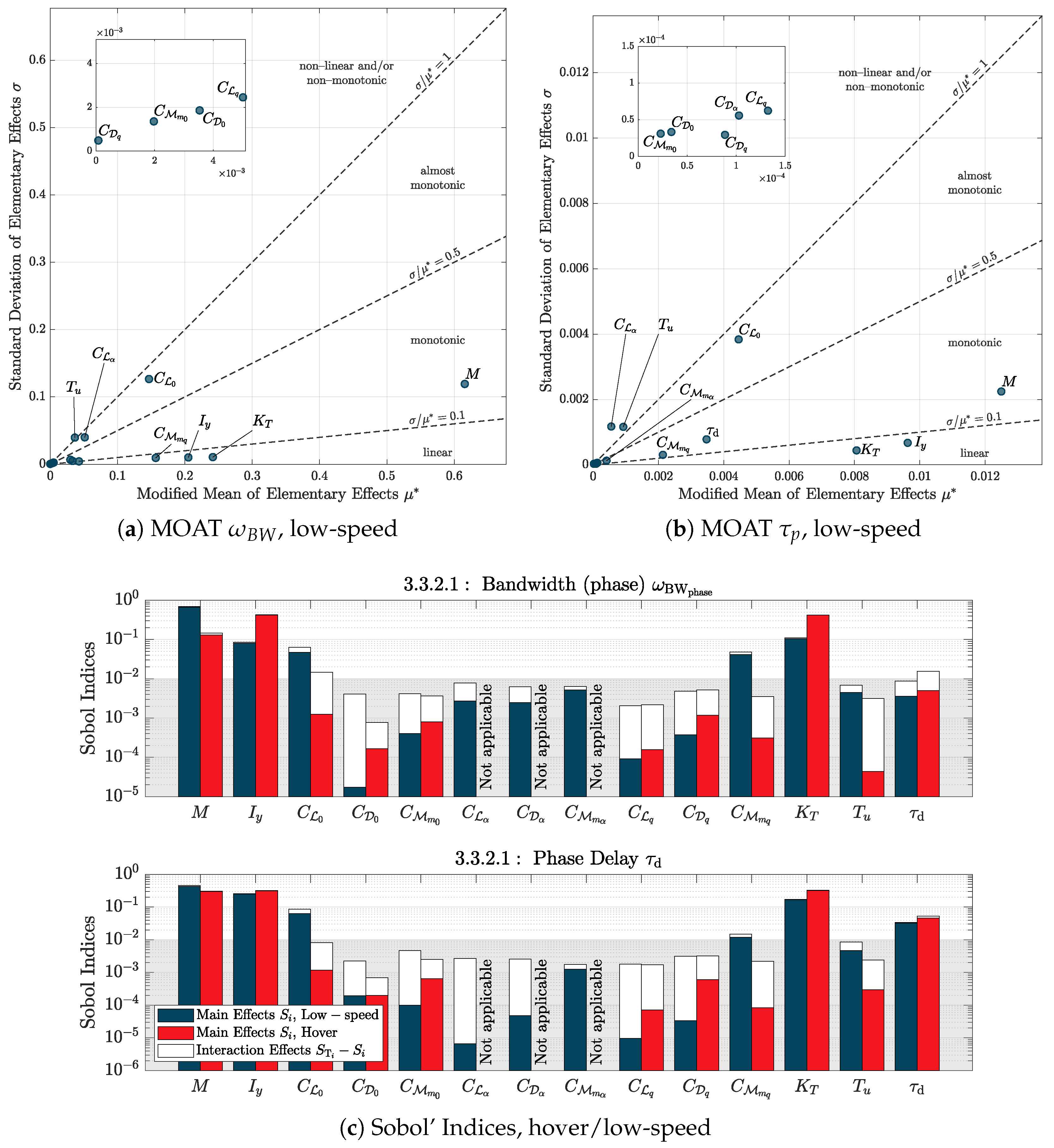
Figure 15.
Bandwidth ADS-33 results from MC analysis
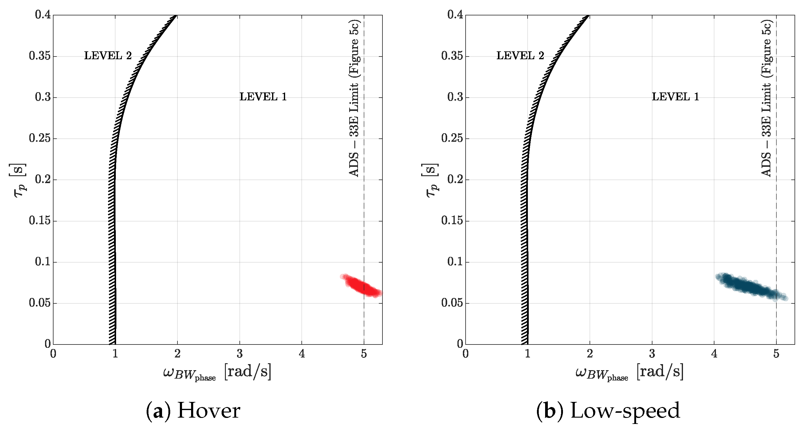
Figure 16.
Selected test configurations, graphical representation

Figure 17.
NFE task performance results. 00 represents the baseline configuration. The colour code refer to the performances: green desired, yellow adequate, red controllable, grey uncontrollable.
Figure 17.
NFE task performance results. 00 represents the baseline configuration. The colour code refer to the performances: green desired, yellow adequate, red controllable, grey uncontrollable.
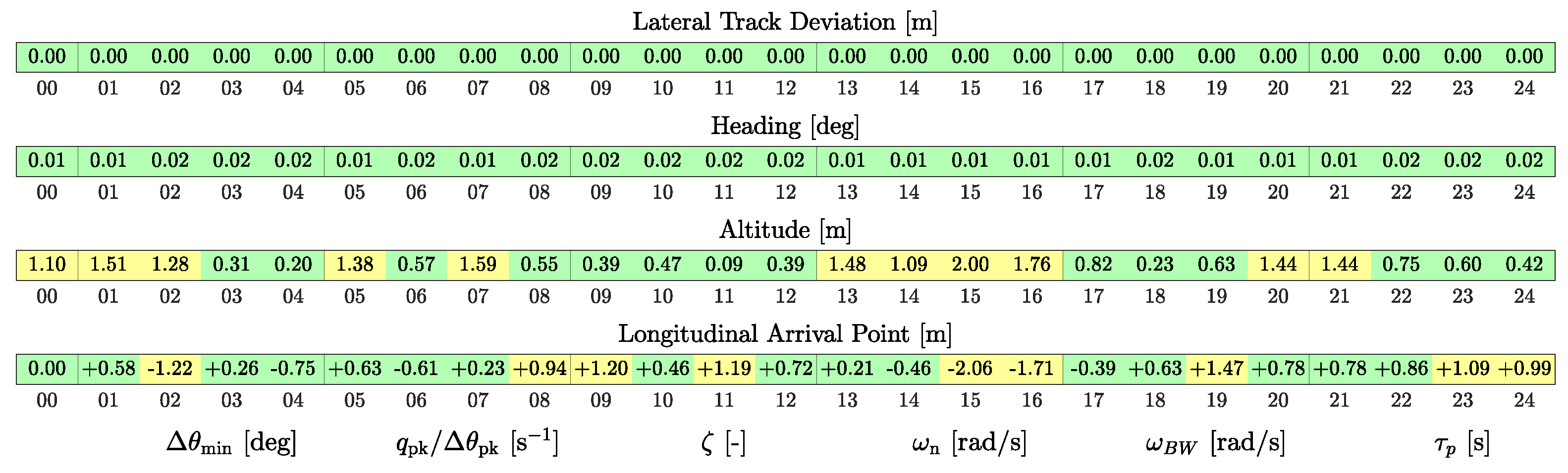
Figure 18.
Recorded time histories with atmospheric disturbance
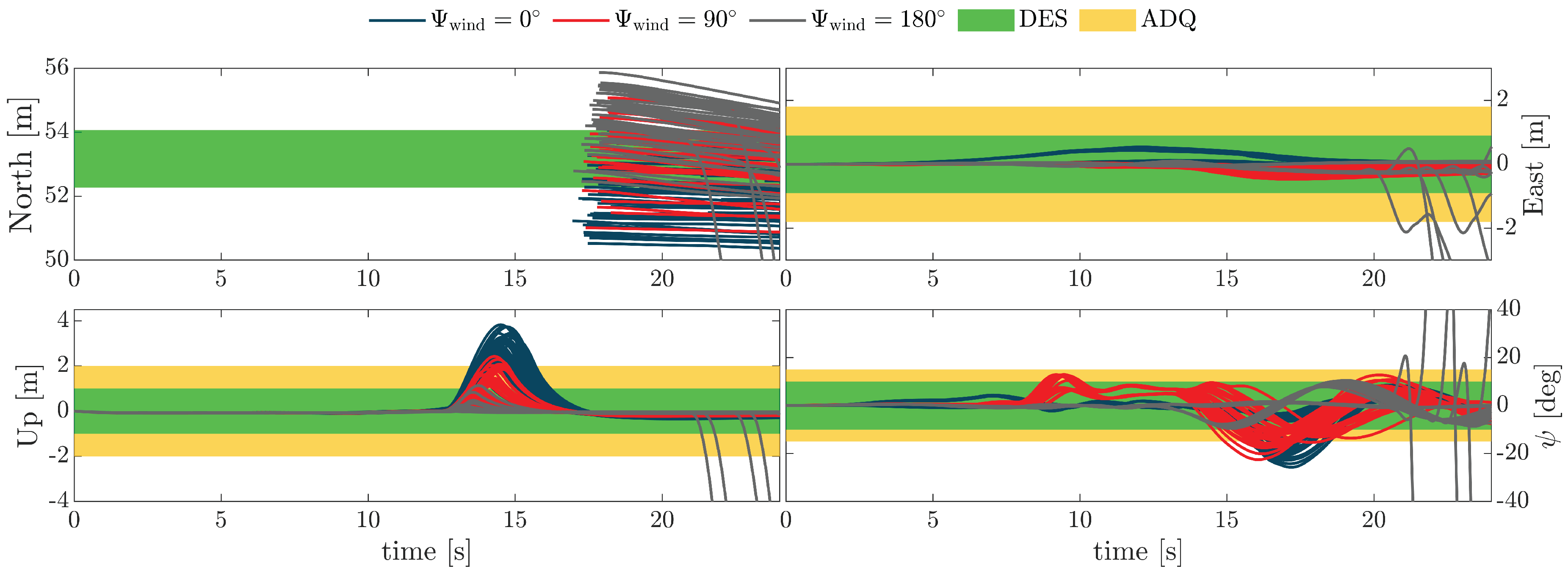
Figure 19.
Task performance results with atmospheric disturbances, for varying incoming wind direction (N-E-S) and magnitude (1 and 2 ). 00 represents the baseline configuration. The colour code refer to the performances: green desired, yellow adequate, red controllable, grey uncontrollable
Figure 19.
Task performance results with atmospheric disturbances, for varying incoming wind direction (N-E-S) and magnitude (1 and 2 ). 00 represents the baseline configuration. The colour code refer to the performances: green desired, yellow adequate, red controllable, grey uncontrollable
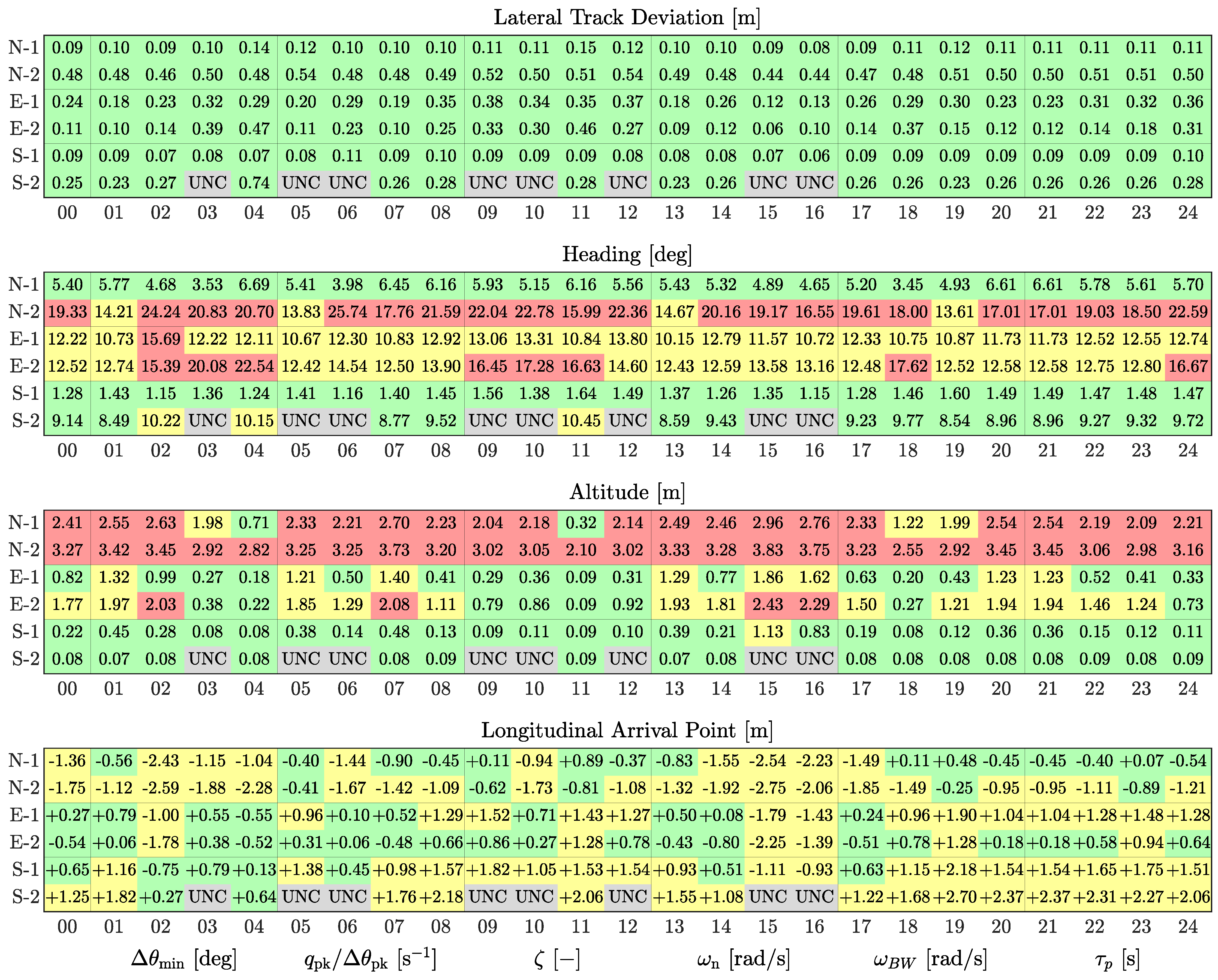
Figure 20.
MUAD analysis on transfer function, due to MC uncertainty
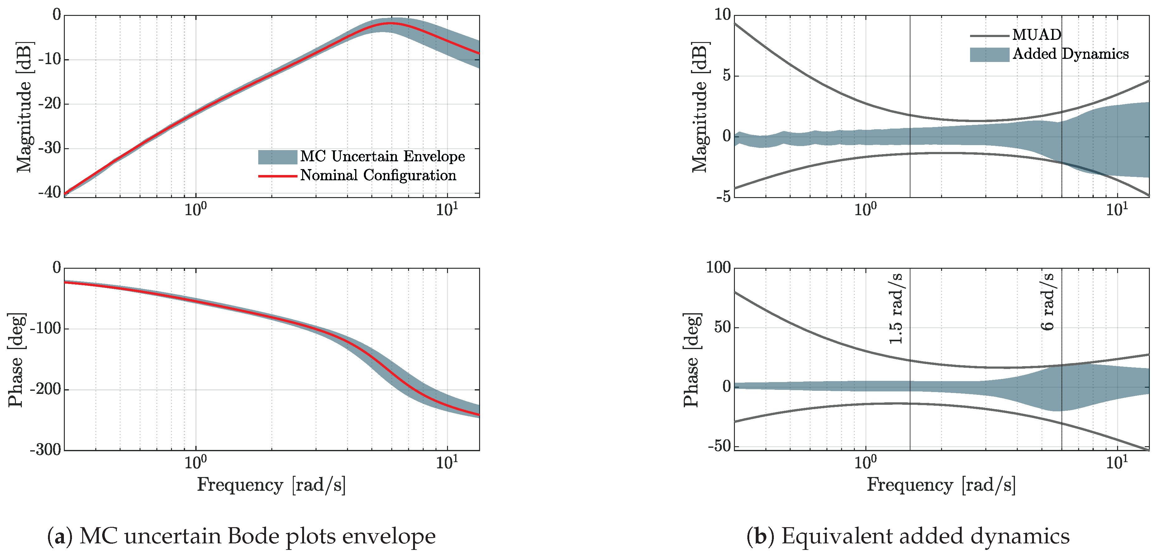
Figure 22.
Bode plots of added and resulting dynamics for varying (0.25-0.70)
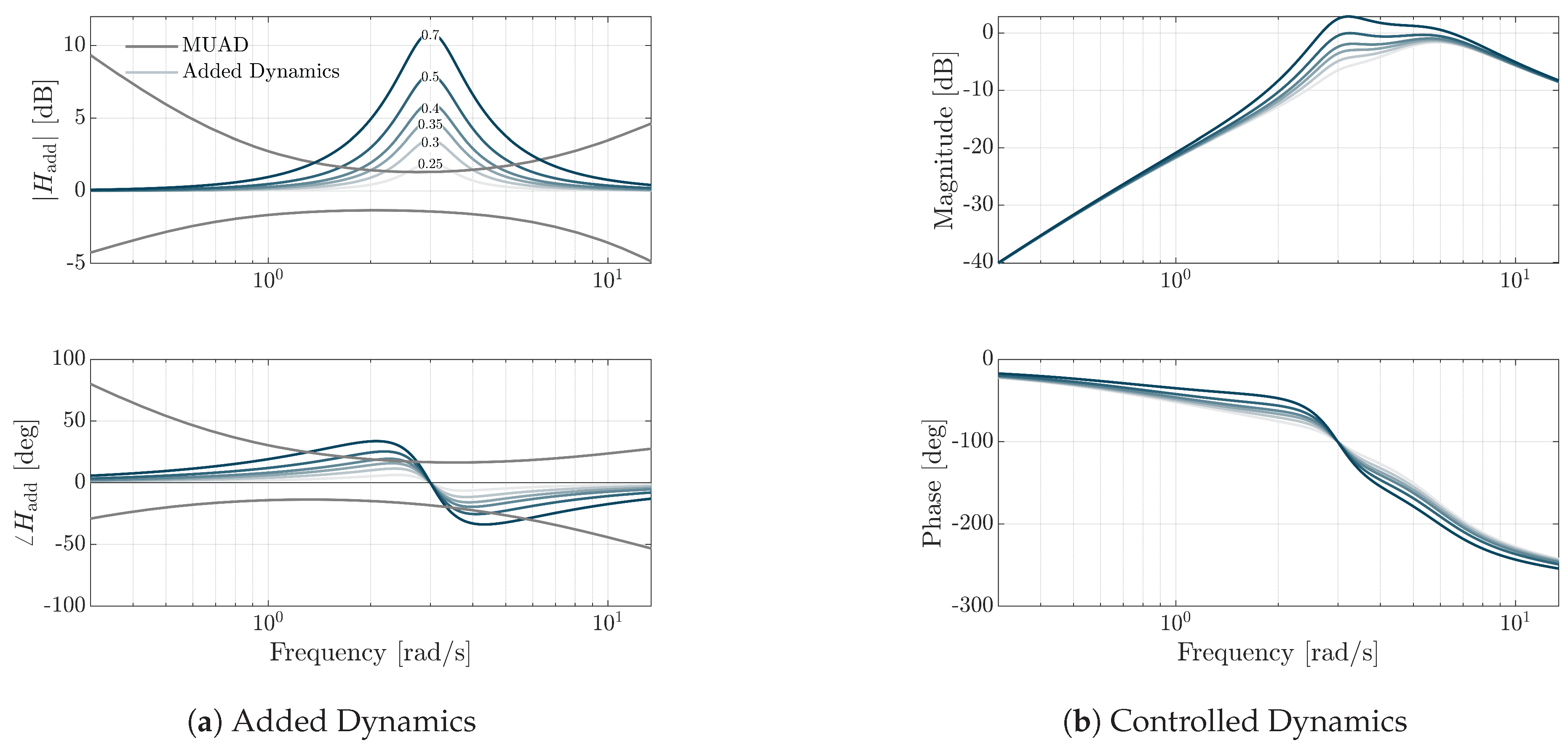
Figure 23.
Results for varying , No Wind (left), m/s (centre), m/s (right)
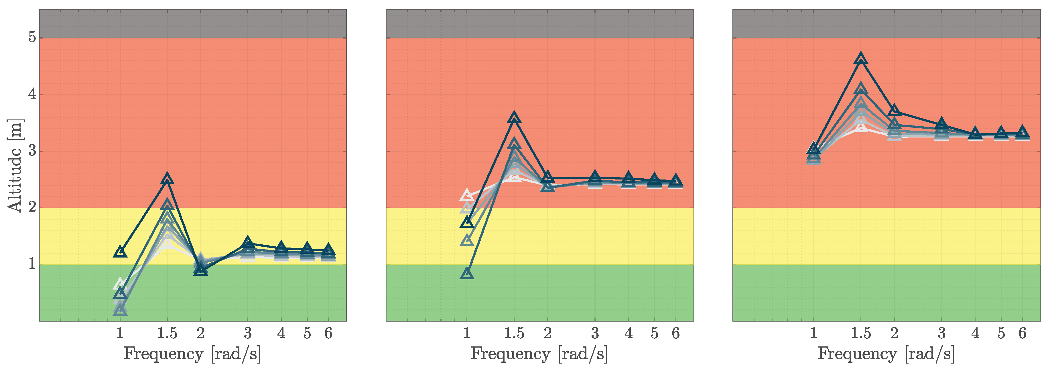

Table 1.
HQ Ratings definition [1].
Table 1.
HQ Ratings definition [1].
| HQ Rating | Description | FC | CHR |
|---|---|---|---|
| Satisfactory (SAT) | HQ allow achievement of desired performance criteria without exceptional piloting skills and with no or minimal pilot compensation | Up to Minor | 1–3 |
| Adequate (ADQ) | HQ allow achievement of desired performance criteria or adequate performance criteria without exceptional piloting skills and with moderate to extensive pilot compensation | Major | 4–6 |
| Controllable (CON) | HQ DO NOT allow achievement of adequate performance criteria WITHOUT exceptional piloting skills. Allows, however, continued safe flight and landing, without exceptional piloting skills, after a transient condition or reconfiguration to retain control, if necessary | Hazardous | 7–9 |
Table 2.
eVTOL main design and performance specifications.
| Parameter | Value | Unit |
|---|---|---|
| Cruise speed | 15 | m/s |
| Stall speed | 11 | m/s |
| Maximum speed | 22 | m/s |
| Max Gross Weight | 7 | kg |
| Wing and fuselage span | 3.12 | m |
| Wing chord | 0.25 | m |
| Wing incidence | 4.5 | deg |
| Horizontal stabilizer span | 0.721 | m |
| Horizontal stabilizer chord | 0.13 | m |
| Horizontal stabilizer arm | 1.08 | m |
| Vertical propeller diameter | 0.178 | m |
| Vertical propeller chord at 80% radius | 0.0124 | m |
Table 3.
Deceleration to Hover FTM Performance Criteria [4].
Table 3.
Deceleration to Hover FTM Performance Criteria [4].
| Description | Desired | Adequate |
|---|---|---|
| Maintain lateral track within meters from ground reference line | ||
| Maintain the heading within degrees | deg | deg |
| Maintain radar altitude within feet | 3 ft | 6 ft |
| The aircraft must be brought to a controlled hover within X meters of the intended endpoint. Overshoots are not permitted |
Table 4.
Uncertain input factors for UA, pitch test.
| Description | Factor | Value | Range | Unit |
|---|---|---|---|---|
| Mass/Inertia | M | 7 | kg | |
| 0.7237 | kg·m2 | |||
| Rotor Parameters | – | |||
| 1 | – | |||
| 0 | s | |||
| 0- Coefficients | 0.7745 | – | ||
| 0.0183 | – | |||
| -0.0240 | – | |||
| -derivatives | 5.1270 | – | ||
| 0.2558 | – | |||
| -0.5402 | – | |||
| q-derivatives | 7.6136 | – | ||
| 0.7179 | – | |||
| -16.169 | – |
Table 6.
MUAD Envelopes Transfer Functions [31].
Table 6.
MUAD Envelopes Transfer Functions [31].
| Envelope Type | Transfer Function |
|---|---|
| Upper Gain Envelope | |
| Lower Gain Envelope | |
| Upper Phase Envelope | |
| Lower Phase Envelope |
Disclaimer/Publisher’s Note: The statements, opinions and data contained in all publications are solely those of the individual author(s) and contributor(s) and not of MDPI and/or the editor(s). MDPI and/or the editor(s) disclaim responsibility for any injury to people or property resulting from any ideas, methods, instructions or products referred to in the content. |
© 2025 by the authors. Licensee MDPI, Basel, Switzerland. This article is an open access article distributed under the terms and conditions of the Creative Commons Attribution (CC BY) license (http://creativecommons.org/licenses/by/4.0/).
Copyright: This open access article is published under a Creative Commons CC BY 4.0 license, which permit the free download, distribution, and reuse, provided that the author and preprint are cited in any reuse.