
Submitted:
10 May 2025
Posted:
13 May 2025
You are already at the latest version
Abstract
Blind and visually impaired (BVI) people face multiple challenges in terms of perception, navigation and safety when traveling. Although there are infrastructures such as blind alleys and pavement markings in cities, the design and maintenance of these facilities are often inadequate to fully meet the needs of traveling. Traditional travel aids usually rely on crutches or simple acoustic feedback, with poor flexibility and interactivity, making it difficult to effectively cope with complex travel environments. Therefore, it is especially necessary to design a set of intelligent and real-time travel assistive devices. Based on this, this paper proposes a set of travel assistance devices based on deep learning. The hardware part of the device includes the main controller-NVIDIA Jetson Nano, the environment sensing unit-D435i depth camera and the feedback unit-SG90 servo. In the software part, in order to meet the limitation of the embedded device's arithmetic power, this paper designs a lightweight target detection and segmentation algorithm to realize obstacle detection and forward direction guidance, which mainly includes a multi-scale attention feature extraction backbone network, a dual-stream fusion module combined with the Mamba architecture, and detection and segmentation heads capable of adaptive context-awareness. The algorithm has high topicality and computational efficiency, which makes it possible to meet the needs of blind people traveling on low-power embedded devices. The overall workflow of the system is as follows: firstly, the binocular depth camera D435i captures real-time information about the surrounding environment; then, the processor recognizes and analyzes the acquired data and converts the obstacle distance and road direction offset signals into Arduino electrical signals, and finally, the servo provides the vibration feedback in order to guide and warn the blind. After the field test, the results show that the device can help the blind find and avoid obstacles in time, correct the traveling position deviation, and meet the real-time requirements of the blind traveling.
Keywords:
blind and visually impaired
; deep learning
; light weighting
; topicality
; vibration feedback
1. Introduction
According to the World Health Organization (WHO), about 2.2 billion people around the world suffer from varying degrees of visual impairment and are unable to perform normal daily activities [1], and it is expected that the population of visually impaired people will surge to 11 billion by 2100. The transportation and mobility problems of the blind and visually impaired (BVI), as an important livelihood issue that needs to be solved urgently, have long received extensive attention from the government and all sectors of society. Visual impairment poses great challenges to the blind and visually impaired in navigating complex environments and unfamiliar spaces, often triggering anxiety and fear. With the aging of the global population, the demand for visual aids is growing significantly as the group of blind and visually impaired people continues to expand. In order to alleviate the difficulties and high risks associated with mobility for the blind and visually impaired, visual guide technology is becoming an important aid.
The application of visual guide technology involves a variety of environmental scenarios, including indoor, outdoor and stairs, etc., and each scenario faces different needs. In these complex environments, even if a blind or visually impaired person is equipped with an assistive device such as a guide dog or cane, he or she may still have difficulty walking safely due to a lack of critical information. The information that blind and visually impaired people need in unfamiliar environments includes: (1) environmental information such as road obstacles; (2) traffic guidance information such as crosswalks and blind alleys; and (3) orientation information such as one's own position and direction. Only when this information is comprehensively and accurately transmitted, the travel risk of the blind and visually impaired can be effectively reduced. However, the existing market guide devices have a single function, and most of them only provide obstacle avoidance function, which cannot meet the actual needs of the blind and visually impaired people in daily traveling. At the same time, due to long-term wear and tear or irregular occupation of the blind road surface there are serious spatial positioning problems, which increases the difficulty of the blind and visually impaired people walking. Especially in crosswalk, traffic lights and other traffic intersections, the blind and visually impaired people's travel risk coefficient is significantly increased, the traditional guide cane cannot provide them with real-time traffic information, resulting in the blind and visually impaired people in these busy, complex areas when traveling face a very high safety risk, easy to traffic accidents.
To address the above problems, this paper proposes an innovative solution - an assistive device based on visual guide technology, combining deep learning algorithms and edge computing, aiming to provide comprehensive environment perception information for the blind and visually impaired in real time to help them avoid obstacles and correct their traveling direction in time. The main contributions of this paper are as follows:
- A practical hardware system of travel assistance device for the blind is built. The NVIDIA Jetson nano embedded platform is used as the edge computing device, combined with the D435i depth camera for environment sensing, and the Arduino microcontroller and SG90 servo to realize vibration feedback. While meeting the functional requirements, the device considers the portability and practicality, providing a stable hardware foundation for the blind to travel assistance.
- In order to solve the problem of limited computing power of edge devices, a new lightweight object detection and segmentation network model was designed. The network model is mainly composed of three parts: a multi-scale attention feature extraction backbone network, a dual-stream feature fusion module combined with the Mamba architecture, and an adaptive context-aware detection segmentation head. In the road segmentation and obstacle detection tasks, compared with the baseline network, the accuracy of the algorithm is significantly improved, for example, the mAPmask of road segmentation is increased by 2.7 percentage points, and the mAP of obstacle detection is increased by 3.1 percentage points. At the same time, the computational complexity is greatly reduced, the model size, parameter number and GFLOPs are reduced, and the frame rate is maintained at a high level (more than 95 FPS for road segmentation and more than 90 FPS for obstacle detection), effectively balancing accuracy and efficiency, making it run well on low-power embedded devices and meet the real-time needs of blind travel.
- Through many experiments, the effectiveness and superiority of the equipment and algorithm are comprehensively verified. In terms of data collection and processing, multi-source data is carefully integrated, enhanced and annotated to ensure data quality. The ablation experiments clearly demonstrate the important role and improvement effect of each module of the algorithm, and the comparative experiments show that the algorithm has significant advantages in accuracy, lightweight and real-time performance compared with various typical networks such as yolov9c-seg, yolov10n and other typical networks in road segmentation and obstacle detection tasks, such as the road segmentation mAPmask reaches 0.979 and the model is only 5.1MB, and the obstacle detection mAP reaches 0.757 and the model is only 5.2MB. It fully proves its potential in practical application and provides strong support for the development of travel assistance technology for the blind.
2. Related Work
Individuals who are visually impaired typically depend on family members, canes, or guide dogs to navigate their environment. The most preferred method is accompanied by family members; however, this method is time-consuming. Walking sticks, while offering some assistance, are limited in their capacity to provide comprehensive environmental information. Guide dogs, while more effective, face challenges in terms of popularity due to their high cost and the complexity of their training.
Consequently, contemporary guide devices have been developed, including electronic walking sticks, electronic guide dogs, and GPS guide systems. These devices employ technologies such as radar, infrared, and ultrasound to facilitate the perception of the surrounding environment and assist blind individuals in navigating their surroundings safely.
For example, Petsiuk et al. [2] propose a low-cost, open-source ultrasound-based wearable bracelet type that conveys point-distance information by means of active detection, provides haptic feedback, and generates vibrations at different frequencies depending on the target range, but its narrow scanning angle and limited response speed make it easy to overlook the dangers posed by small, fast-moving objects. Papagianopoulos et al. [3] proposed a way to fix an infrared sensor on the top of a blind person's arm to detect the internal environment of a building through the principle of infrared thermal imaging to guide the blind person to move, but it can only detect important obstacles in the blind person's path, which has certain limitations.
With the continuous development of robotics, multiform and multifunctional guide robots continue to enter the public eye [4], avoiding dangerous accidents by sensing their surroundings and reducing the cognitive work required to navigate in unfamiliar areas. For example, Lu et al. [5] proposed an assisted guidance robot based on DRL, which can effectively avoid obstacles and achieve navigation in dynamic pedestrian environments. Although guide robots can help blind people move more independently, the development, manufacturing and maintenance costs of guide robots are high, and there are some technical challenges that make it difficult to be widely used.
In recent years, with the rapid development of artificial intelligence technology, the GPU computing power continues to increase, making more deep learning in the field of image processing and environment perception [6], and the convolutional neural network also occupies a place in the visual perception, so that the auxiliary travelling method based on deep learning has gained more attention from experts and scholars. Cao et al. [7] proposed a lightweight semantic segmentation network for fast and accurate segmentation of blind lanes and sidewalks, using deep separable convolution and densely connected void space pyramid pooling modules to improve the segmentation speed and accuracy. Dimas et al. [8] proposed an obstacle detection method that combines deep learning, object recognition models, and human eye gaze prediction based on generative adversarial networks, aiming to provide outdoor navigation solutions for people with limited vision, and conduct obstacle risk assessment and spatial localization through fuzzy logic methods to help users navigate safely and avoid obstacles. Ma et al. [9] proposed a blind obstacle segmentation system based on E-BiSeNet neural network to help visually impaired people walk safely through real-time and accurate obstacle recognition and avoidance. Hsieh et al. [10] proposed a wearable guidance device based on video streaming and deep learning to help blind or visually impaired people identify flat and safe walking routes by using RGB cameras and convolutional neural networks (CNNs) to convert images into depth maps. Suman et al. [11]proposed a "Vision Navigator" framework for predictive analytics, which realizes real-time detection and classification of obstacles through intelligent folding canes and sensor shoes, combined with single detection (SSD) and recurrent neural network (RNN) models, and improves the independent navigation ability of visually impaired people. Mai et al. [12] proposed an intelligent guidance system for the blind based on 2D LiDAR and RGB-D cameras, which integrates laser SLAM and improved YOLOv5 algorithm, which can identify a variety of obstacles in real time and guide intelligent crutches to avoid obstacles, providing efficient indoor and outdoor navigation functions for the visually impaired. Chen et al. [13] proposed a wearable navigation device based on semantic vision SLAM and mobile computing platform, which extracts environmental semantic information in real time through RGB-D cameras, and helps visually impaired people avoid obstacles and understand their surroundings in the form of voice feedback.
Therefore, this paper designs a set of travel assistance equipment for the blind and visually impaired based on deep learning and edge computing, which integrates the NVIDIA Jetson Nano main control platform and a variety of sensors, combined with lightweight and efficient road segmentation and obstacle detection algorithms, and has accurate drivable area segmentation and obstacle detection capabilities, so as to better assist the blind and visually impaired to travel and improve travel safety.
3. Hardware System Build
NVIDIA Jetson nano is a small, cost-effective embedded platform designed for artificial intelligence (AI) and Internet of Things (IoT) applications, featuring a 128-core Maxwell-based GPU, a quad-core ARM Cortex-A57 processor, and 4GB of memory. It supports a wealth of development tools and AI frameworks, and is suitable for scenarios such as robotics, intelligent monitoring, and IoT devices. Jetson Nano is easy to use, provides powerful computing power with the JetPack SDK, and has an active developer community, making it ideal for getting started and developing AI and embedded system applications. Table 1 shows the hardware configuration of deep learning models that can run deep learning models efficiently.
The traveling aid for Blind and visually impaired (BVI) people studied in this paper is mainly composed of NVIDIA Jetson nano, D435i depth camera, Arduino microcontroller, 2 SG90 servos, 24V lithium battery, and its hardware control system integration is shown in Figure 1.
The overall flow of the equipment is shown in Figure 2. First, the depth camera D435i perceives the surrounding environment and depth information, and then transmits the acquired image information to the AI edge computing device. After the lightweight detection and segmentation algorithm is processed, the corresponding offset and angle calculation are carried out on the detection and segmentation results, and the obstacle azimuth signal and road offset signal are generated by combining the depth information. The network output is sent to the Arduino microcontroller through the UART interface, and the Arduino microcontroller connects two SG90 servos through the GPIO pin, which vibrates in the lower part of the human ear to remind the blind person to adjust the driving route and avoid obstacles.
4. Method
In practical applications, although NVIDIA Jetson Nano provides good computational performance and supports the operation of common AI frameworks, due to its limited hardware resources (e.g., 128-core GPU and 4GB RAM), it is difficult to achieve high real-time requirements by directly running some complex deep learning models. Especially when dealing with larger-scale models or multitasking scenarios, the performance bottleneck of Jetson Nano leads to frame rate degradation, affecting the speed and accuracy of detection. Therefore, in order to achieve more efficient inference on embedded platforms, this paper designs a lightweight model to enhance its real-time and energy-efficient performance in resource-constrained environments. The network model is mainly composed of three parts: the feature extraction backbone, the feature fusion module, and the target detection and segmentation head, and its structure is shown in Figure 3.
The network takes a 3-channel color image as the input, and firstly passes through two convolutional layers with a step length of 2 and a kernel size of 3, combined with the activation function (SiLU) and normalization (BatchNorm, BN), and performs preliminary feature extraction on the input image. This stage not only effectively extracts the basic features of the image, but also lays the foundation for normalized and nonlinear expression for subsequent feature extraction. Subsequently, the network further improved the expression ability of features through the Efficient Depthwise Activation Block (EDAB) and the Multi-Scale Context Attention Unit (MSCA) stacked three times in a row. Among them, EDAB reduces the computational cost through deep separable convolution while preserving details; MSCA captures spatial and contextual information through multi-scale convolution and attention mechanisms, optimizes the selectivity of channels and spatial features, and significantly reduces redundant calculations. Finally, the features are fused at multiple scales through the SPPF module, which further enhances the unity of global semantics and detailed features.
In the decoding stage, the network uses stepwise upsampling to recover the spatial resolution of features, and combines the Dual Stream Feature Fusion Module (DSFFM) to realize the collaborative capture of information between global and local features. In the form of double branches, DSFFM focuses on local detail modeling and global context information extraction, which makes the feature expression in the decoding process richer. Subsequently, the fused features were further optimized by Convolutional Block Search (CBS), and the CBS module strengthened the feature expression ability through convolution, activation and normalization operations. At the same time, through multi-level Upsample and Concat operations, features at different levels are gradually fused, in which low-resolution global semantic features and high-resolution fine-grained features are organically combined, balancing the expression of details and semantic information, and laying a solid foundation for detection and segmentation tasks.
Finally, the network completes the output of the final target detection frame and segmentation mask by combining grouped convolution, deformable convolutional network v4 (DCNv4), and adaptive context-aware detection and segmentation header (ACADSH) with channel attention mechanism. Grouped convolution reduces computational overhead, deformable convolution enhances the ability to model irregular target shapes, and the channel attention mechanism further optimises feature selectivity and weight assignment. This design allows the network to maintain excellent lightweight performance while maintaining high performance, making it ideal for applications in resource-limited devices and complex scenarios.
4.1. Multi-Scale Attention Feature Extraction Backbone
Multi-scale feature extraction is the key to achieve efficient feature characterization for deep learning models in target detection and segmentation tasks. In this study, a novel network structure combining EDAB and MSCA is designed in the backbone part. Assuming an input image, each channel of the input is firstly subjected to an independent convolution operation by a 3×3 convolution kernel, followed by fusion of the inter-channel information using a 1×1 convolution kernel, and the number of output channels is Cout. then the feature distribution is adjusted using the BN, and finally, a SiLU activation function is applied to further extract the more complex features, and the structure is shown in Figure 4.
The output of the above-mentioned preliminary feature extraction module is fed into the MSCA, and the structure of the unit is shown in Figure 5. It consists of Multisemantic Spatial Attention Block (MSAB), Spatial Reconstruction Block (SRB), Progressive Channel Attention Block (CPAB) and Channel Reassembly Block (CRB), each part is closely connected with each other, and gradually strengthens the ability to express features.
MSAB is the first part of MSCA, which is mainly responsible for enhancing the expression ability of input features from different spatial directions, providing fine spatial context information, and providing high-quality initial input for subsequent modules to optimize feature structure. Specifically, the input feature is pooled globally along the X and Y directions to generate a 1D sequence in the width and height directions, representing XH and XW, respectively, and then applying grouping operations to XH and XW to extract the sub-features of different groups:
where denotes the number of channels in each group, K is the number of groups, and represents the selected channel range.
Next a depth separable convolution operation is applied to each sub-feature (with convolution kernel sizes of 3, 5, 7, 9) and they are spliced in height and width dimensions. Normalization is then performed by Group Normalization and directional attention weights are generated by a gating mechanism (Sigmoid):
where Concat denotes the splicing feature group along the channel dimension, and GNK represents group normalization.
Finally, the multi-semantic space features are weighted to the original input feature X to form the enhanced feature:
where denotes element-by-element multiplication, weighting the original feature map with attention weights.
SRB is the second part of MSCA, which directly receives the spatial features optimized by MSAB and further eliminates redundant information in spatial dimension. SRB provides more efficient feature input for channel optimization by evaluating the importance of different channels in the input features and extracting spatially significant information. The specific implementation is to normalize the feature output from MSAB:
where denotes the mean of the feature map in the spatial dimension, denotes the variance of the feature map in the spatial dimension, denotes a small constant for avoiding divide-by-zero errors, denotes the corresponding learnable scaling and offset parameters for each channel.
The importance of each channel is then evaluated using the parameter of the GN output, and the weight value is obtained and the final channel selection weight W is generated by the Sigmoid function:
The weight W divides the feature map into valid features containing semantic information and cluttered features containing redundant information:
where W1 denotes that the weights in W that are greater than the threshold (set to 0.5) are set to 1 and the rest to 0, and W2 (1-W1) denotes the remaining redundant weights.
The final spatial reconstruction features are finally generated by weighted summation and stitching operations:
CPAB is the third part of MSCA, which is closely connected with SRB, and further optimizes the feature expression on the channel dimension through the lightweight attention mechanism, providing multi-dimensional global contextual information for the subsequent modules. The output feature XP of SRB are first compressed in spatial dimensions by a global pooling operation, a step that preserves global semantic information and significantly reduces computational complexity. Then a depth-separable convolution is used to generate the query, Q.; key, K.; and value V. The original features are mapped to three different feature spaces, and a weight matrix is generated through a self-attention mechanism, which is used to weight the value feature V to generate a new channel feature Xattn. Finally, the channel-attention feature Xattn is further optimized through global pooling and normalization, and fused with the original input features:
where denotes the learnable projection matrix, * denotes the convolution operation, denotes the inter-channel attention weight matrix, denotes the normalization factor, and XO denotes the augmented output features.
CRB is the final part of MSCA, which receives the CPAB-optimized features and further refines the feature representation in the channel dimension. The final channel optimized output is provided through feature decomposition, group convolution and fusion strategies. The output features XO from CPAB are first decomposed along the channel dimension into an upper channel part Xup and a lower channel part Xlow. for Xup, multi-level features are extracted using Group Conv and PWConv, and for Xlow, fine-grained information is preserved using PWConv and Concat operations. Finally, the upper and lower channel features are fused by the weighting coefficients generated by Softmax:
where is a learnable 1×1 convolutional kernel, denotes the channel division ratio, denotes the fusion weights of the upper and lower channels, and Y denotes the optimized channel information.
4.2. Dual-Stream Feature Fusion Module
The direct splicing of encoder and decoder features often triggers semantic mismatch problem, which affects the model performance. To solve this problem, this paper designs a dual-stream feature fusion enhancement module, which improves the expression of features and enhances the context consistency through a multi-path feature optimization mechanism. The structure is shown in Figure 6.
Initial fusion features are first generated by CBS processing. Subsequently, it is divided into two branches: the trunk path and the context path, which are used to capture local detail features and global context information, respectively. The backbone path gradually extracts local features through multiple Bottleneck Blocks (containing CBS and residual connections). The context path gradually extracts global features through multiple VSE Blocks.
The context path is further divided into the following steps: the input features are normalized by layers and then divided into two branches, in the first branch, the input passes through the linear layer and the SiLU activation function in turn. In the second branch, the input first passes through the linear layer, depth separable convolution, and SiLU activation function in turn, and then feeds into the SCE module (which contains three parts: scanning, extraction, and filtering), which takes four different directions of scanning to unfold into a 1D sequence, and the image scanning process is shown in Figure 7.
The features are then extracted and filtered using linear transformation and recursive computation, combined with exponential operations and feature decomposition mechanisms to distinguish between relevant and irrelevant information, and the input features are mapped into three feature subspaces by linear mapping:
where : B, L, D denote the batch size, sequence length, and feature dimension, respectively, ΔA, B, C denote the feature components generated by linear transformation, and denotes the linear mapping.
Secondly, in order to capture the nonlinear correlation of the features and efficiently model the contextual relationships in the sequence features, exponential operations and matrix decomposition are performed on the generated features ΔA、ΔB, and the recursive mechanism is used to update the hidden states:
where exp(ΔA) is an element-by-element exponential operation, I denotes the unit matrix, ht denotes the hidden state feature at the current moment, ht-1 denotes the hidden state feature at the previous moment, and xt denotes the input feature at the current moment.
Next, it combines the hidden state feature ht with the current input feature xt and stitches all the moments to get the complete output feature:
Where C denotes the weights for adjusting the hidden state features, D denotes the redundant information used to filter the current input features, and y denotes the optimized context information.
Finally, the first and second branch outputs are merged and mixed by element-by-element multiplication and the outputs of the VSE Block are generated by residual concatenation. And the output features of trunk path and context path are merged again with the features processed by CBS through Concat operation and further optimized by CBS to generate the final output features.
4.3. Adaptive Context-Aware Detection and Segmentation Head
In the task of target detection and instance segmentation, the detection head and segmentation head are the key output parts in the whole network. In order to improve the detection accuracy and segmentation performance while considering the computational efficiency, this paper designs a unified detection and segmentation head module based on deformable convolution. This module can simultaneously handle bounding box prediction (BBox) and category prediction (Cls) for target detection and mask coefficients prediction (Mask Coefficients) for instance segmentation, and its structure is shown in Figure 8.
It is mainly composed of three parts: Deformable Convolution with Squeeze and Excitation (DCNSE), Conv2D and Loss Calculation Unit. The end-to-end outputs of detection and segmentation are realized uniformly through the multi-task structure design.
Among them, DCNSE is the core of the detection and segmentation head, which aims to enhance the modeling capability of target shape and local features through DCNv4, and at the same time adaptively adjust the importance of different channel features by combining with the channel attention mechanism (Squeeze-and-Excitation, SE). On the one hand, GroupConv, BN and ReLU activation functions are used to reduce the number of parameters and improve the training stability and nonlinear representation. On the other hand, the local and geometric deformation features of the input features are extracted by DCNv4, and then the output features are subjected to global average pooling (AvgPool), which compresses the spatial dimensions and retains only the global statistical information of the channels. Then, the pooled features are nonlinearly transformed by linear mapping with ReLU activation function to enhance the expressive capability; subsequently, the channel weights are generated by a second linear layer with Sigmoid activation function to complete the adaptive weighting of the importance of different channels.
The output of DCNSE enters two sub-task branches: Detection Head and Segmentation Head. The Detection branch is responsible for predicting bounding box regression and category classification. The segmentation branch is used to predict the Mask Coefficients.
5. Experiments and Results
5.1. Data Acquisition and Production
The road area where blind people walk is extended to three categories of blind roads, pedestrian crossings and ordinary roads as the dataset needed for segmentation, a sample of which is shown in Figure 9. Among them, the blind road data comes from the open-source dataset (TP-Dataset), which contains several typical scenes such as campus, street, railway station, bus station, underground, community and hospital, totaling 1391 images. The pedestrian crossing data is from the Kaggle website, totaling 1,100 images. Ordinary road data is taken from the All-Weather Road Image Segmentation dataset (UAS), which includes four types of weather conditions, including dusk, night, rain, and bright sunshine, totaling 6,380 images. The obstacle detection dataset, on the other hand, is taken from the dataset website (Roboflow), covering 12 categories such as pedestrians, bicycles, motorbikes, cars, buses, bins, stone piers, fire hydrants, conical barrels, puddles, green lights at pedestrian intersections, and red lights at pedestrian intersections, totaling 12,300 images, and a sample of the dataset is shown in Figure 10.
To ensure that the data categories are balanced, we randomly selected 1500 images from the general road dataset as part of the segmentation dataset. Since the category labels of the segmentation dataset are all binarized mask images, we processed them using OpenCV's color and edge detection techniques to convert them into the form of coordinates required by the segmentation network. In the obstacle detection dataset, we performed a comprehensive data cleaning operation to eliminate all images with mislabeling and omission to ensure the accuracy and quality of the data. Finally, the processed segmentation and detection dataset was divided into training, validation, and test sets in the ratio of 8:1:1 and fed into the model for training.
5.2. Image Processing
Since the number of samples in the segmented dataset is too small, which can easily lead to the weak generalization ability of the model, the road video is collected from the field around the school and the pictures are intercepted by frame-by-frame extraction, which is merged with the data obtained through major dataset website searching and web crawler technology to form a new dataset, and then the dataset is further expanded through data augmentation means, such as rotating, scaling, translating, color transforming and contrast transforming. The total number of images reaches 6660 (including 2250 images of blind roads, 2310 images of crosswalks, and 2100 images of ordinary roads), and finally the images are manually labeled using the semi-automatic labeling software X-Anylabeling, and the dataset is labeled as shown in Figure 11.
5.3. Experimental Setup and Environment
The hardware and software configuration of the training environment for this experiment is shown in Table 2. The training uses stochastic gradient descent (SGD) and sets the initial learning rate to 0.01, the momentum factor to 0.937, the regularization factor to 0.0005, the input image size to 640x640 pixels, the number of batch processes (batch size) to 32, and the training cycles (epochs) to 200 rounds, and automatically stops the training if there is no performance improvement in 50 cycles. Training. In addition, we used Mixup data enhancement technique [14] to improve the model performance. The training environment is configured as:
For the experimental inference part, Jetson Nano introduced above is used as the inference platform. It has low power consumption and strong computational capability, which is suitable for deep learning applications in edge devices. In order to comprehensively assess the effectiveness of the improved algorithm in this paper, the following evaluation metrics are used: model scale size (MB), computation amount (GFLOPs), number of parameters (M), mean average precision (mAP), mask mean average precision (mAPmask), and frame rate (FPS). The model scale size, computation volume and number of parameters are used to measure the storage and computation requirements of the model; while mAP, mAPmask and FPS are used to evaluate the detection accuracy and real-time performance of the model.
5.4. Ablation Experiments
In order to verify the effectiveness of the improved network and enhance the robustness of the model, the ablation experiments were designed by dividing the improved method into three parts: firstly, adding MSAFEB, secondly, adding DSFFM, and thirdly, adding ACADSH, and the results of the ablation experiments are shown in Table 3 and Table 4.
As seen in Table 3, in the road segmentation task, using MSAFEB, DSFFM and ACADSH, respectively, the mask accuracy is improved by 1.1, 1.4 and 0.9 percentage points, and compared with the original network, the improved network model improves by 2.7 percentage points, and a comparison of the results before and after the improvement is shown in Figure 12. Comparison chart of mAP@50 (M), from which the improved model can reduce some training process fluctuations during the training process and converge faster to reach a stable value. In addition, the table shows that the improved module combination reduces the model size by 7.3%, the number of parameters by 5.2%, and the GFLOP by 9.8%. The frame rate is kept above 95 frames/sec, which has strong real-time performance and can meet the demands of many real-world scenarios. Overall, the improved module effectively enhances the comprehensive performance of the segmentation task and achieves a good balance between accuracy and efficiency.
As seen in Table 4, the detection accuracy (mAP) is improved by 1.5, 1.9 and 0.2 percentage points in the obstacle detection task using MSAFEB, DSFFM and ACADSH, respectively. Compared with the baseline network, the improved network model has an overall improvement of 3.1 percentage points, and a comparison of the results before and after the improvement is shown in Figure 13. Comparison chart of mAP@50 (B). In addition, as can be seen from the table, the improved module combination reduces the model size by 6.6%, the number of parameters by 7.1%, and the GFLOP by 7.3%. Meanwhile, the frame rate is kept above 90 frames/sec. The improved model not only significantly reduces the computational complexity, but also considers the efficient inference speed, which fully meets the real-time and resource-friendly requirements of the detection model in practical applications.
5.5. Comparative Experiments
In order to further verify the superiority of this paper's algorithm and prove that the improvement of this paper's algorithm can truly improve the performance of the model, a comparison test is designed to conduct an experimental study with the improved model under the same dataset and experimental environment. The four typical example segmentation networks, yolov9c-seg, yolo11s-seg, SAM-2, and Mask-RT-DETR, are used to compare the road segmentation task network, and the comparison of evaluation indexes of the experimental results is shown in Table 5. Meanwhile, the four latest target detection networks, yolov10n, yolo11, Grounding DINO, RT-DETR, are used to compare the obstacle detection network, and the evaluation index comparison of the experimental results is shown in Table 6.
The data in Table 5 shows that the model proposed in this paper exhibits excellent performance in the road segmentation task, reaching a mAP of 0.979, which is the highest accuracy in the table, while maintaining a real-time performance of 98 FPS, which considers the balance between accuracy and efficiency. In addition, the model size is only 5.1 MB, the number of parameters is 2.69 M, and the computational complexity is 9.8 GFLOPs, which significantly outperforms the other comparative methods in terms of lightness and efficiency, and the results of the algorithm comparison are shown in Figure 14. This shows that the model proposed in this paper greatly reduces the computational cost while improving the segmentation accuracy, and can better adapt to the actual scene requirements, which fully verifies the advancement and effectiveness of its design.
As can be seen from the data in Table 6, the model proposed in this paper shows excellent performance and high efficiency in the obstacle detection task, achieving the highest accuracy of 0.757 mAP, which is significantly improved compared with other methods; meanwhile, it maintains the real-time performance of 98 FPS, and in terms of lightweight, the model size is only 4.7 MB, the number of parameters is 2.47 M, and the computational complexity is 6.1 GFLOPs, which is much lower than other methods. methods, and the algorithm comparison results are shown in Figure 15. These results show that the model designed in this paper achieves an ideal balance between accuracy, efficiency, and resource requirements, and fully verifies its potential and advantages for application in real scenarios.
5.6. Algorithm Results Visualization and Analysis
In order to show the leading effect of the improved algorithm of this paper more intuitively in road segmentation, we select some pictures from the dataset for visualization, as shown in Figure 16. The improved algorithm in this paper has better effect in the edge segmentation part relative to other example segmentation algorithms.
Four additional images of blind people during travel in complex environments were selected to visualize and compare the obstacle detection model, as shown in Figure 17.
The unimproved algorithm model has missed detection in the red circle, while the improved model in this paper has a great improvement in the detection of small and occluded targets, which effectively solves the problem of missed and misdetection of obstacles in the traveling process of the blind.
5.7. Real-World Scenario Test Visualization and Analysis
For the road division part of the processing is through the setting of two baseline, in the baseline to determine the boundary of the white area and the coordinates of the center point, according to the slope of the line connecting the center point K1 to determine the blind walking on the road, the extension direction of the road: K1 <-10 °, the road extends to the left, the need to remind the blind to adjust to the right; -10 ° < K1 < 10 °, the road extends in front of the blind without reminding the blind to adjust; K1 > 10 °, the road extends to the right, need to remind the blind to adjust to the left, as shown in Figure 18. adjustment; when K1>10°, the road extends to the right and the blind person needs to be reminded to adjust to the left front, as shown in Figure 18.
For the obstacle detection part of the processing is first through the D435i depth camera to obtain the distance information of the obstacle, when the distance of the obstacle is less than the set threshold, and then through the angle information to determine whether the need to avoid. The specific way is as follows: connect the bottom center of the road segmentation bounding box with the center of the object detection bounding box to get the slope K2, and judge the direction of the obstacle ahead: when 75° < K2 < 90°, the obstacle appears in the right front; when 90° < K2 < 105°, the obstacle appears in the left front, as shown in Figure 19.
Finally, the trained model was deployed to the edge computing device, NVIDIA Jetson Nano, and tested on ordinary roads, blind roads, and pedestrian crossings on campus, as shown in Figure 20.
The depth image data captured by the D435i camera is first processed into a pseudo-color image, and then an algorithm is implemented to segment the road and detect obstacles. At the same time, the system can also recognize the offset information of the road centerline, the distance and angle information of the obstacles. Whether it is a blind road, a crosswalk or an ordinary road, a better segmentation effect can be obtained. In addition, the system can effectively detect all kinds of obstacles encountered by blind people in the process of traveling, and can accurately recognize obstacles regardless of whether they are static, dynamic, blocked, or unobstructed.
6. Conclusion
In this paper, we design and implement a set of intelligent travel assistive devices based on deep learning and edge computing to address the challenges faced by the BVI people in the process of traveling. The device combines an advanced hardware platform and optimized deep learning algorithms, aiming to enhance the safety and autonomy of BVI people in complex environments. The device uses NVIDIA Jetson Nano as the edge computing platform and is equipped with a D435i depth camera for environment sensing, thus realizing real-time depth information capture of the surrounding environment. With lightweight detection and segmentation algorithms, this device can efficiently perform obstacle detection and road segmentation.
In terms of hardware design, the device adopts a compact and efficient modular structure, integrating key components such as the main control unit, the environment sensing unit and the feedback unit, ensuring the portability and practical applicability of the device. As for the software algorithm, the device can achieve smooth real-time operation on resource-constrained embedded systems through careful lightweight improvement. The experimental results show that the device exhibits excellent performance in both road segmentation and obstacle detection tasks: the mAPmask of the road segmentation task reaches 97.9%, and the mAP of the obstacle detection task reaches 75.7%, and the device maintains a high frame rate (FPS) while maintaining high accuracy, which fully meets the real-time demand.
Compared with existing technologies, this device not only excels in accuracy, but also realizes lightweight and high performance, which has higher commercial value and wide application prospects. Multi-scenario real-world test results further validate the effectiveness and robustness of the device. Through the vibration feedback mechanism, the device can provide real-time navigation tips and obstacle warnings for the BVI people, which significantly improves their traveling experience and safety.
References
- Bourne, R.; Steinmetz, J.D.; Flaxman, S.; et al. Trends in prevalence of blindness and distance and near vision impairment over 30 years: an analysis for the Global Burden of Disease Study. The Lancet global health, 2021, 9, e130–e143. [Google Scholar] [CrossRef] [PubMed]
- Petsiuk, A.L.; Pearce J, M. Low-cost open-source ultrasound-sensing based navigational support for the visually impaired. Sensors, 2019, 19, 3783. [Google Scholar] [CrossRef] [PubMed]
- Papagianopoulos, I.; De Mey, G.; Kos, A.; et al. Obstacle detection in infrared navigation for blind people and mobile robots. Sensors, 2023, 23, 7198. [Google Scholar] [CrossRef] [PubMed]
- Wu Z, H. , Rong, X. W.; Fan Y. Review of research on guide robots. Computer Engineering and Applications, 2020, 56, 1–13. [Google Scholar]
- Lu, C.L.; Liu, Z.Y.; Huang, J.T.; et al. Assistive navigation using deep reinforcement learning guiding robot with UWB/voice beacons and semantic feedbacks for blind and visually impaired people. Frontiers in Robotics and AI, 2021, 8: 654132. [CrossRef]
- Arulkumaran, K.; Deisenroth, M.P.; Brundage, M.; et al. Deep reinforcement learning: a brief survey. IEEE Signal Processing Magazine, 2023, 34, 26–38. [Google Scholar] [CrossRef]
- Cao, Z.; Xu, X.; Hu, B.; et al. Rapid detection of blind roads and crosswalks by using a lightweight semantic segmentation network. IEEE Transactions on Intelligent Transportation Systems, 2020, 22, 6188–6197. [Google Scholar] [CrossRef]
- Dimas, G.; Diamantis, D.E.; Kalozoumis, P.; et al. Uncertainty-aware visual perception system for outdoor navigation of the visually challenged. Sensors, 2020, 20, 2385–2394. [Google Scholar] [CrossRef] [PubMed]
- Ma, Y.; Xu, Q.; Wang, Y.; et al. EOS: an efficient obstacle segmentation for blind guiding. Future Generation Computer Systems, 2023, 140, 117–128. [Google Scholar] [CrossRef]
- Hsieh, Y.Z.; Lin, S.S.; Xu, F.X.; et al. Development of a wearable guide device based on convolutional neural network for blind or visually impaired persons. Multimedia Tools and Applications, 2020, 79, 29473–29491. [Google Scholar] [CrossRef]
- Suman, S.; Mishra, S.; Sahoo, K.S.; et al. Vision navigator: a smart and intelligent obstacle recognition model for visually impaired users. Mobile Information Systems, 2022, 33, 891–971. [Google Scholar] [CrossRef]
- Mai, C.; Chen, H.; Zeng, L.; et al. A smart cane based on 2D LiDAR and RGB-D camera sensor-realizing navigation and obstacle recognition. Sensors, 2024, 24, 870–886. [Google Scholar] [CrossRef] [PubMed]
- Chen, Z.; Liu, X.; Kojima, M.; et al. A wearable navigation device for visually impaired people based on the real-time semantic visual SLAM system. Sensors, 2021, 21, 1536–1542. [Google Scholar] [CrossRef] [PubMed]
- Zhang, H. mixup: Beyond empirical risk minimization. arXiv:1710.09412, 2017.
- Wang, C.Y.; Yeh, I.H.; Mark Liao H, Y. Yolov9: Learning what you want to learn using programmable gradient information. European Conference on Computer Vision. Springer, Cham, 2025: 1-21. [CrossRef]
- Khanam, R.; Hussain, M. Yolov11: An overview of the key architectural enhancements. arXiv:2410.17725, 2024.
- Ravi, N.; Gabeur, V.; Hu, Y.T.; et al. Sam 2: Segment anything in images and videos. arXiv:2408.00714, 2024.
- Zhao, Y.; Lv, W.; Xu, S.; et al. Detrs beat yolos on real-time object detection. Proceedings of the IEEE/CVF Conference on Computer Vision and Pattern Recognition. 2024: 16965-16974. [CrossRef]
- Wang, A.; Chen, H.; Liu, L.; et al. Yolov10: Real-time end-to-end object detection. arXiv:2405.14458, 2024.
- Liu, S.; Zeng, Z.; Ren, T.; et al. Grounding dino: Marrying dino with grounded pre-training for open-set object detection. European Conference on Computer Vision. Springer, Cham, 2025: 38-55. [CrossRef]
Figure 1.
Hardware control system integration diagram.
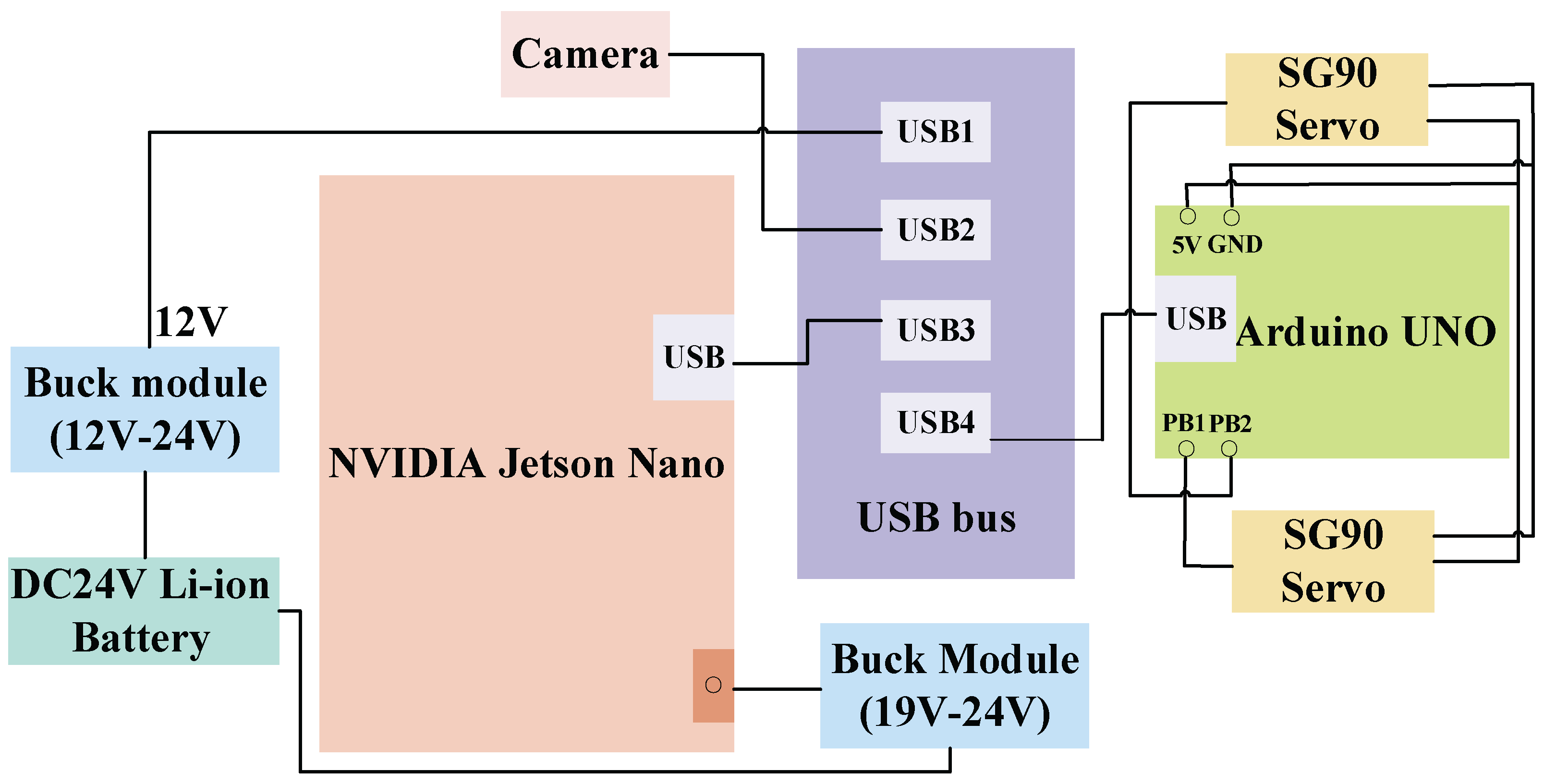
Figure 2.
Device workflow diagram.
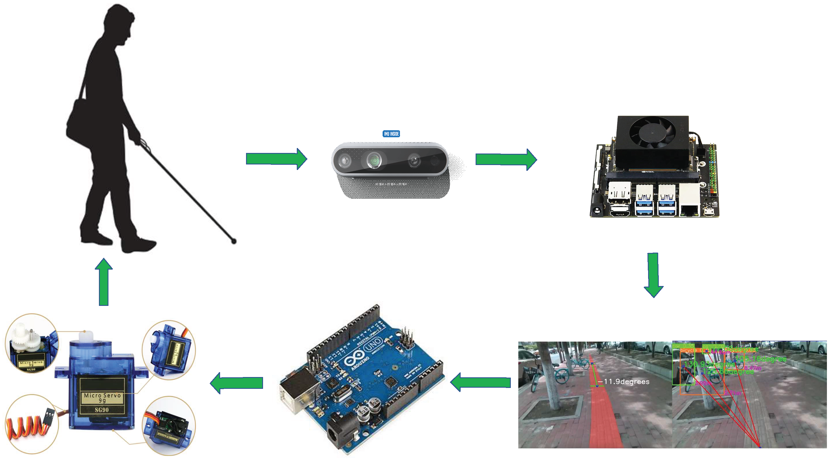
Figure 3.
Diagram of the overall network structure.
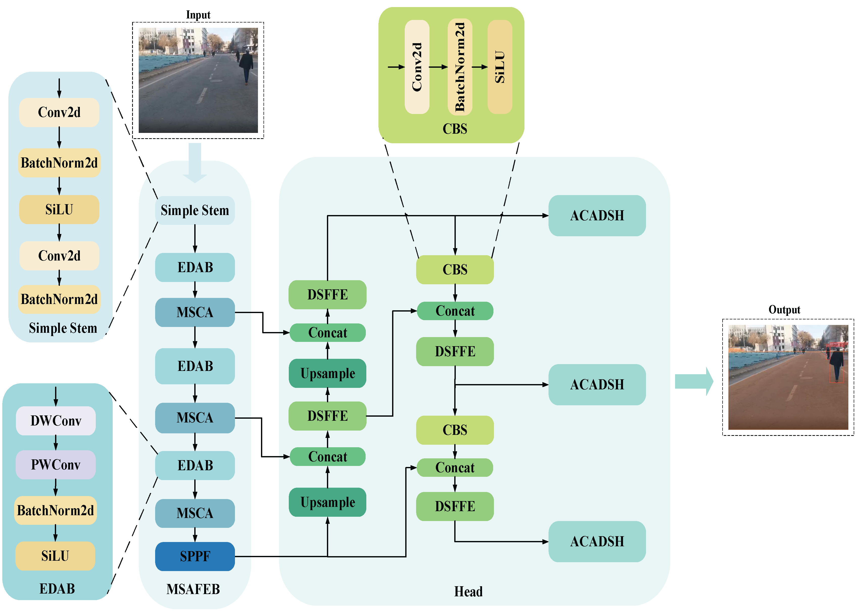
Figure 4.
EDAB structural diagram.
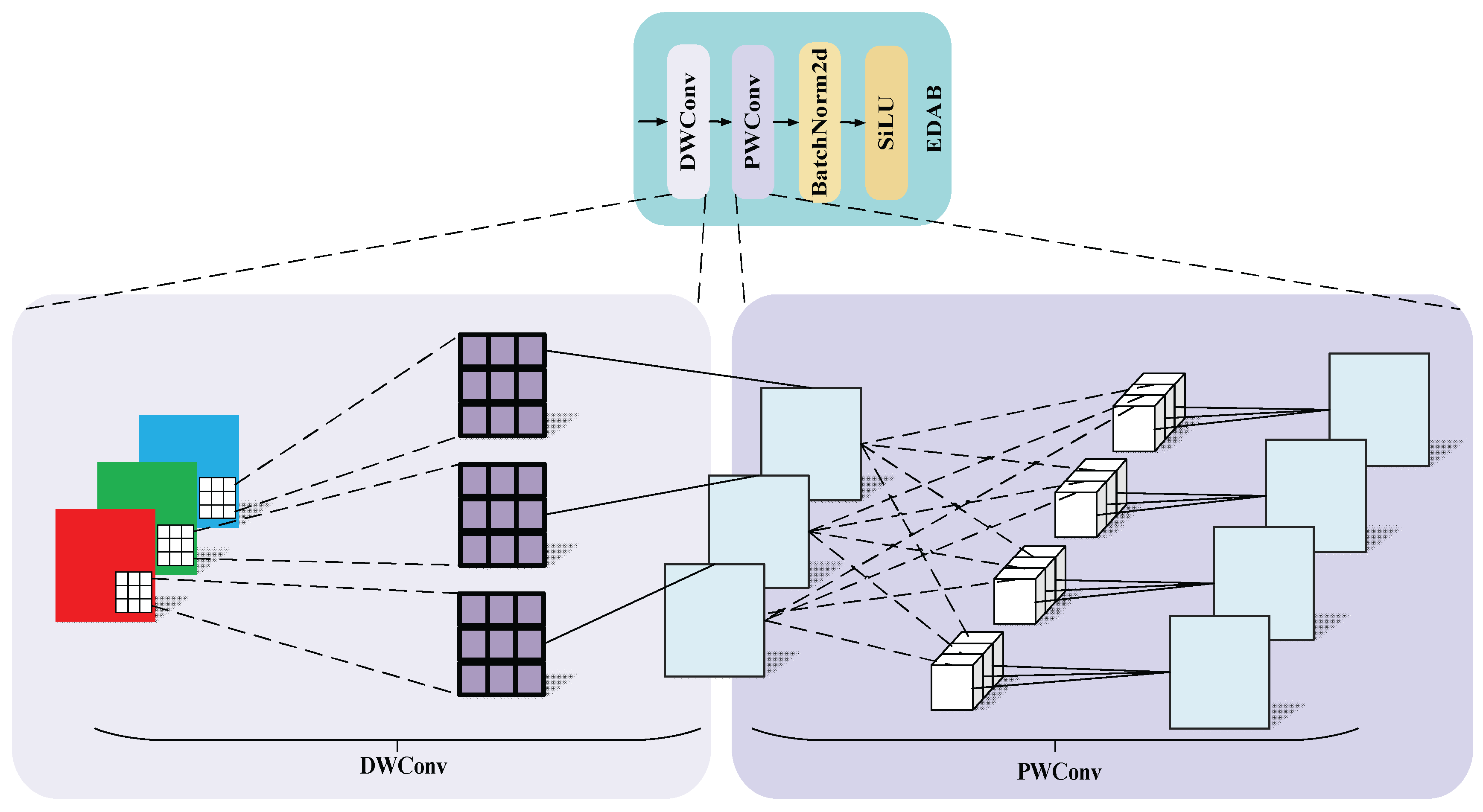
Figure 5.
MSCA structural diagram.
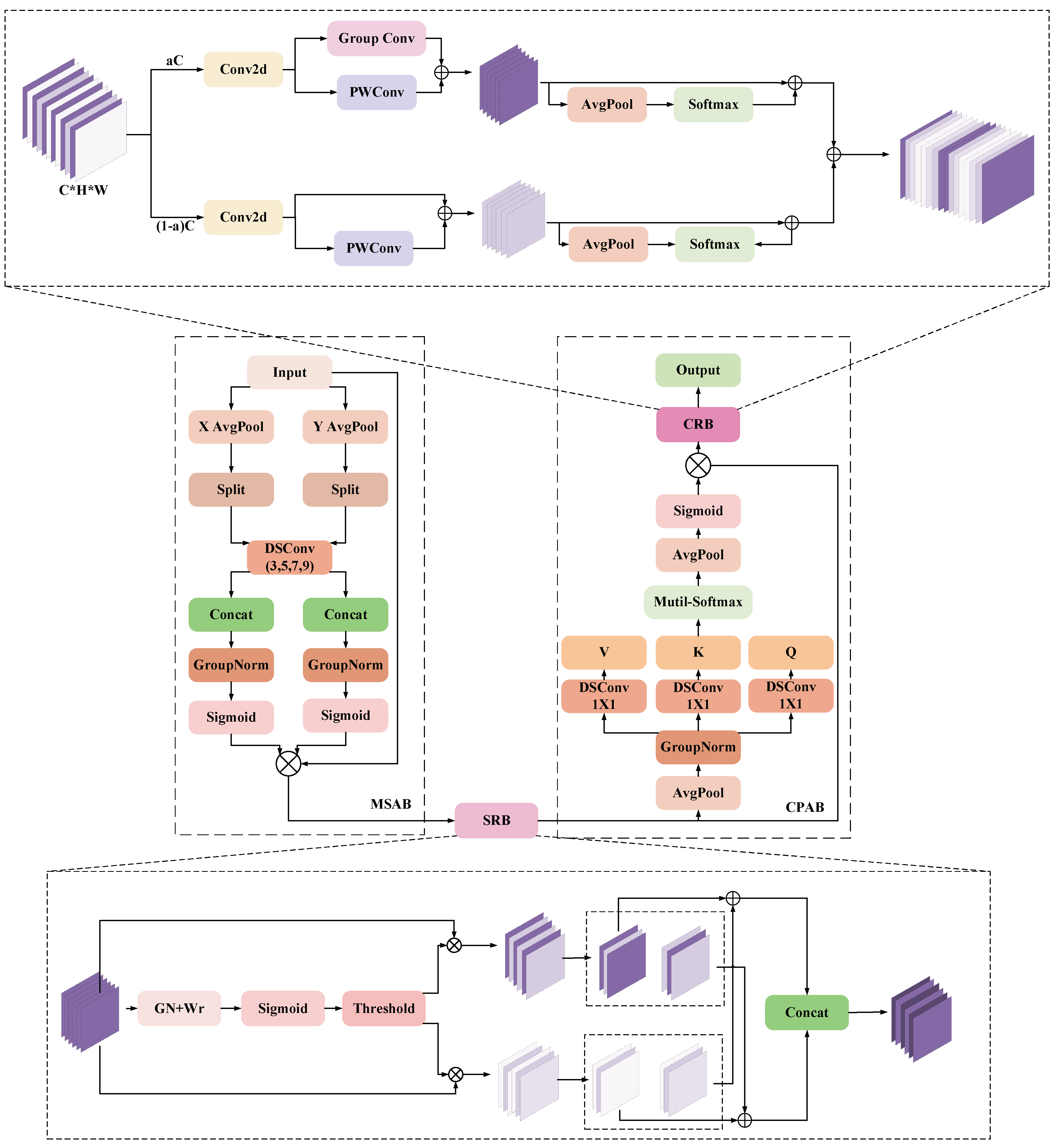
Figure 6.
DSF structural diagram.
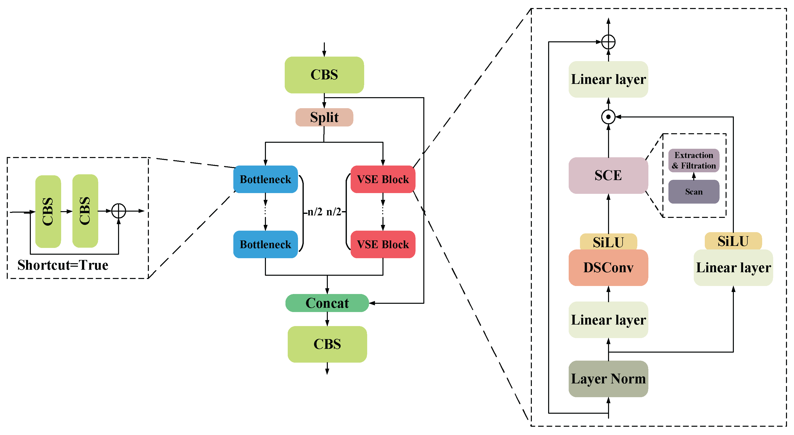
Figure 7.
Schematic of the four different scanning processes.
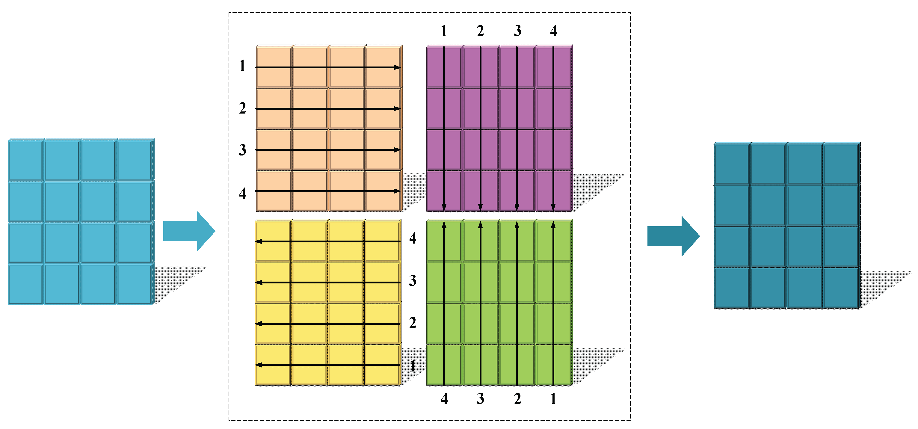
Figure 8.
ACADSH structural diagram.
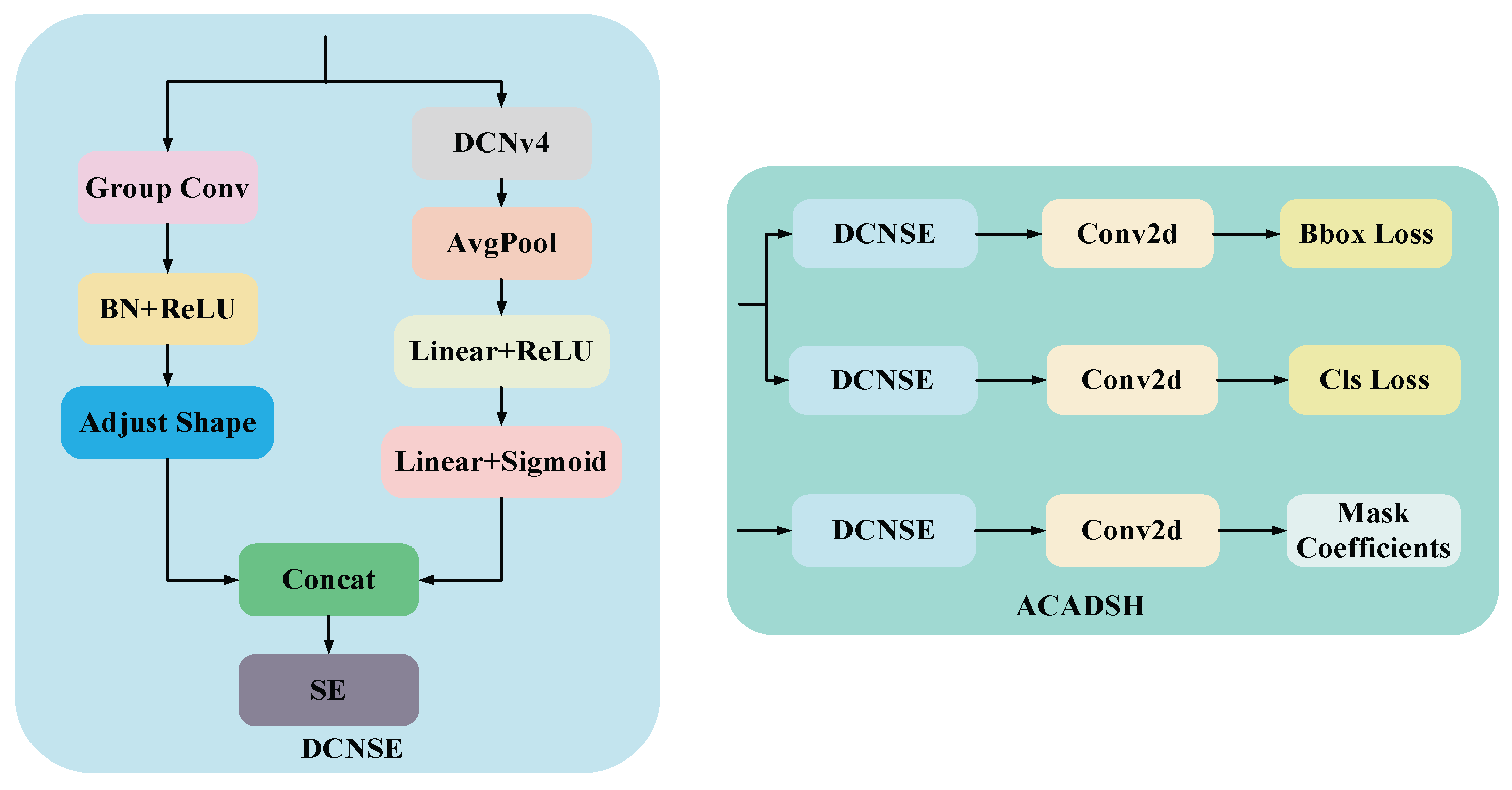
Figure 9.
Partial sample of a segmentation dataset.
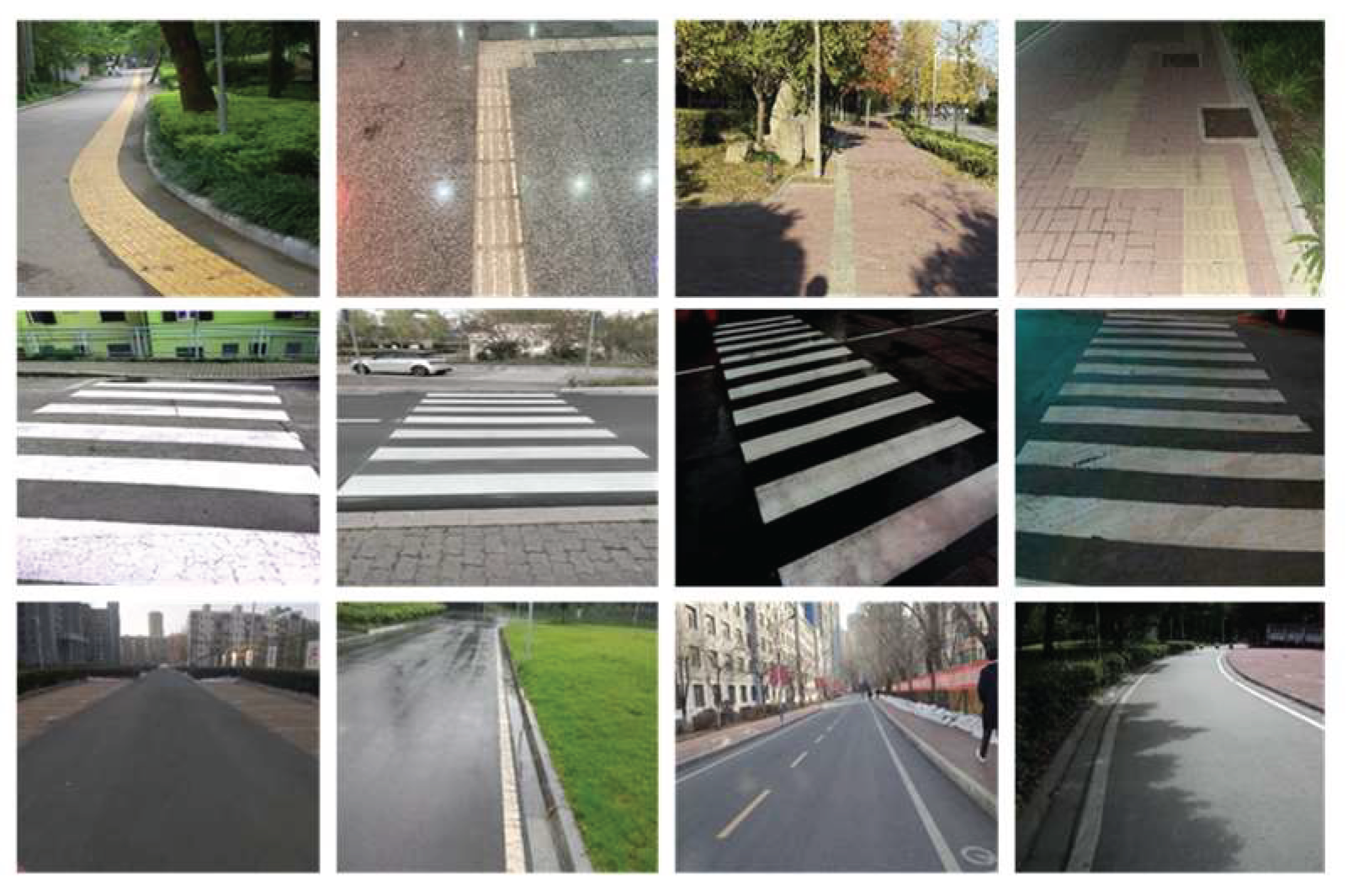
Figure 10.
Partial sample of the detection dataset.
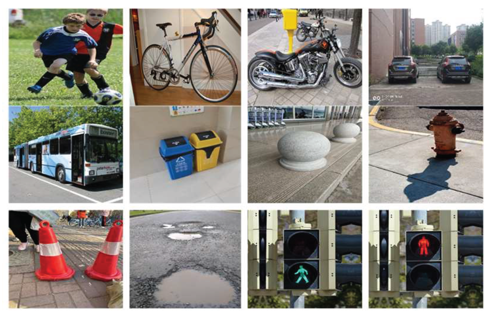
Figure 11.
Dataset labeling process.
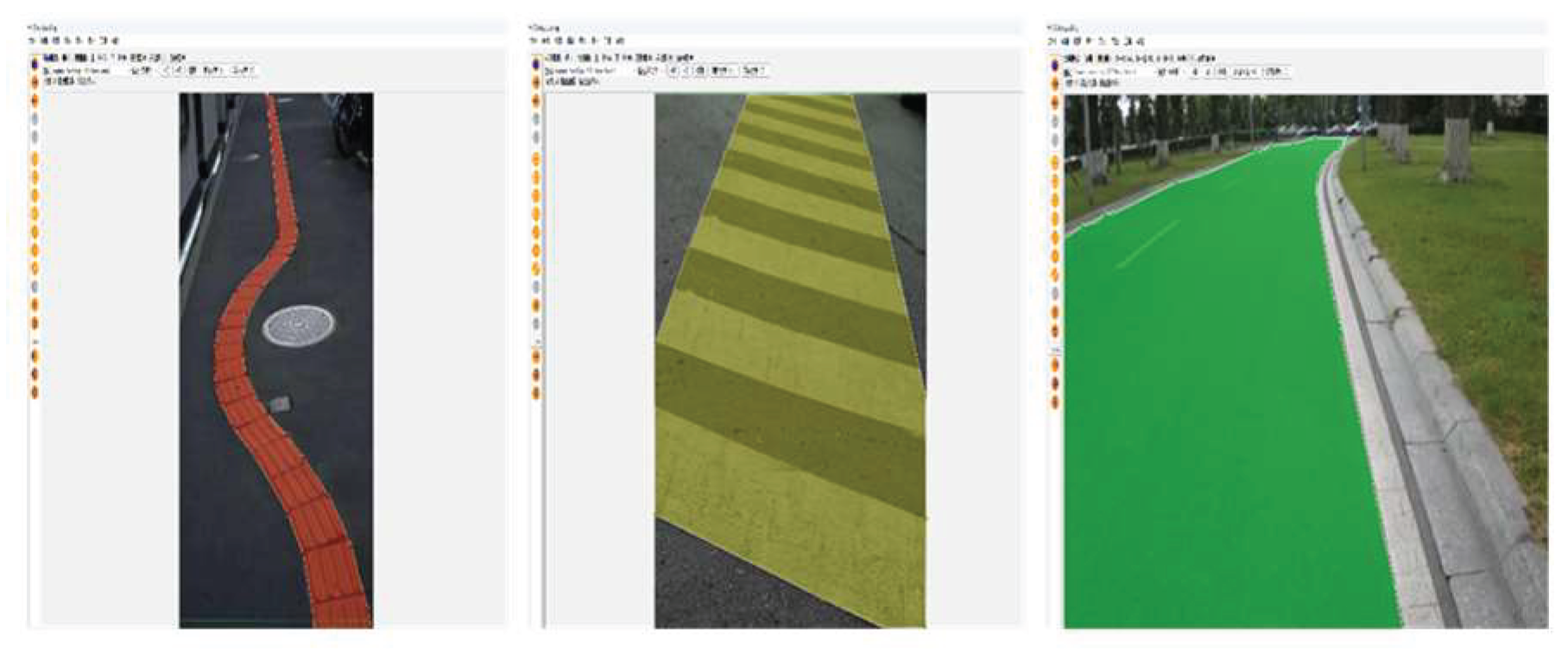
Figure 12.
Comparison chart of mAP@50 (M).
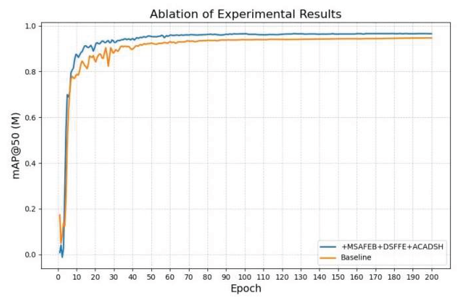
Figure 13.
Comparison chart of mAP@50 (B).
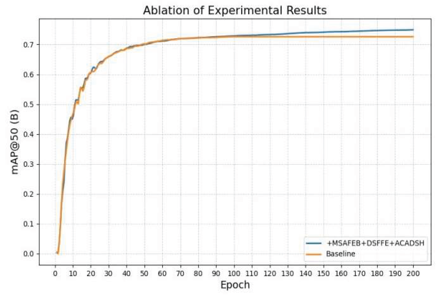
Figure 14.
Comparison Chart of Typical Algorithms.
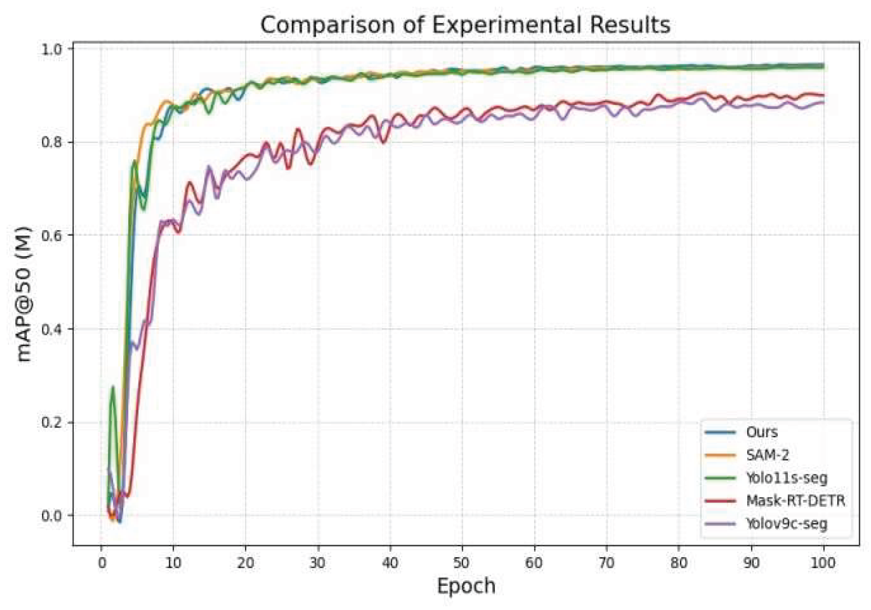
Figure 15.
Comparison Chart of Typical Algorithms.

Figure 16.
Comparison of the effects of different algorithms.
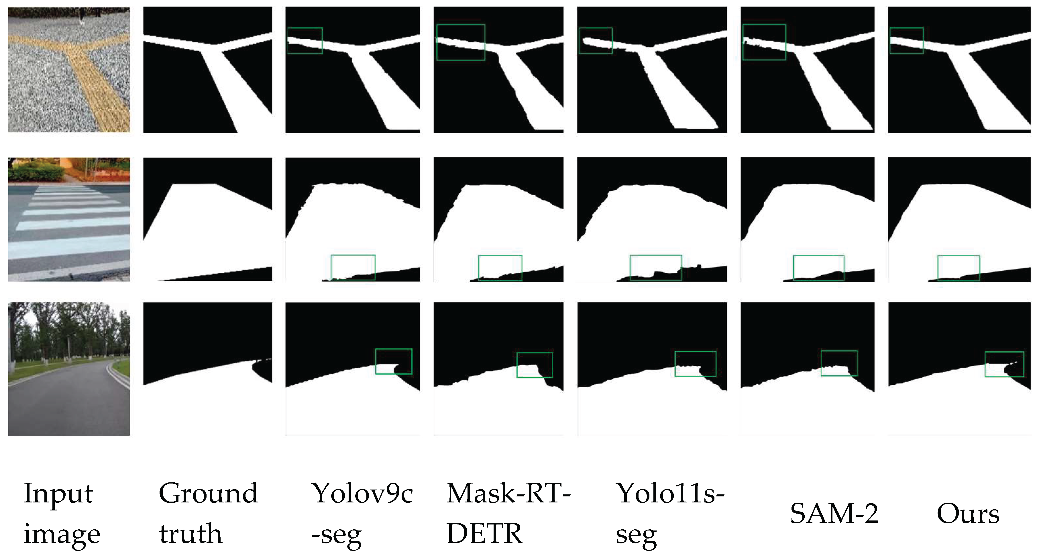
Figure 17.
Improved before and after performance comparison chart.
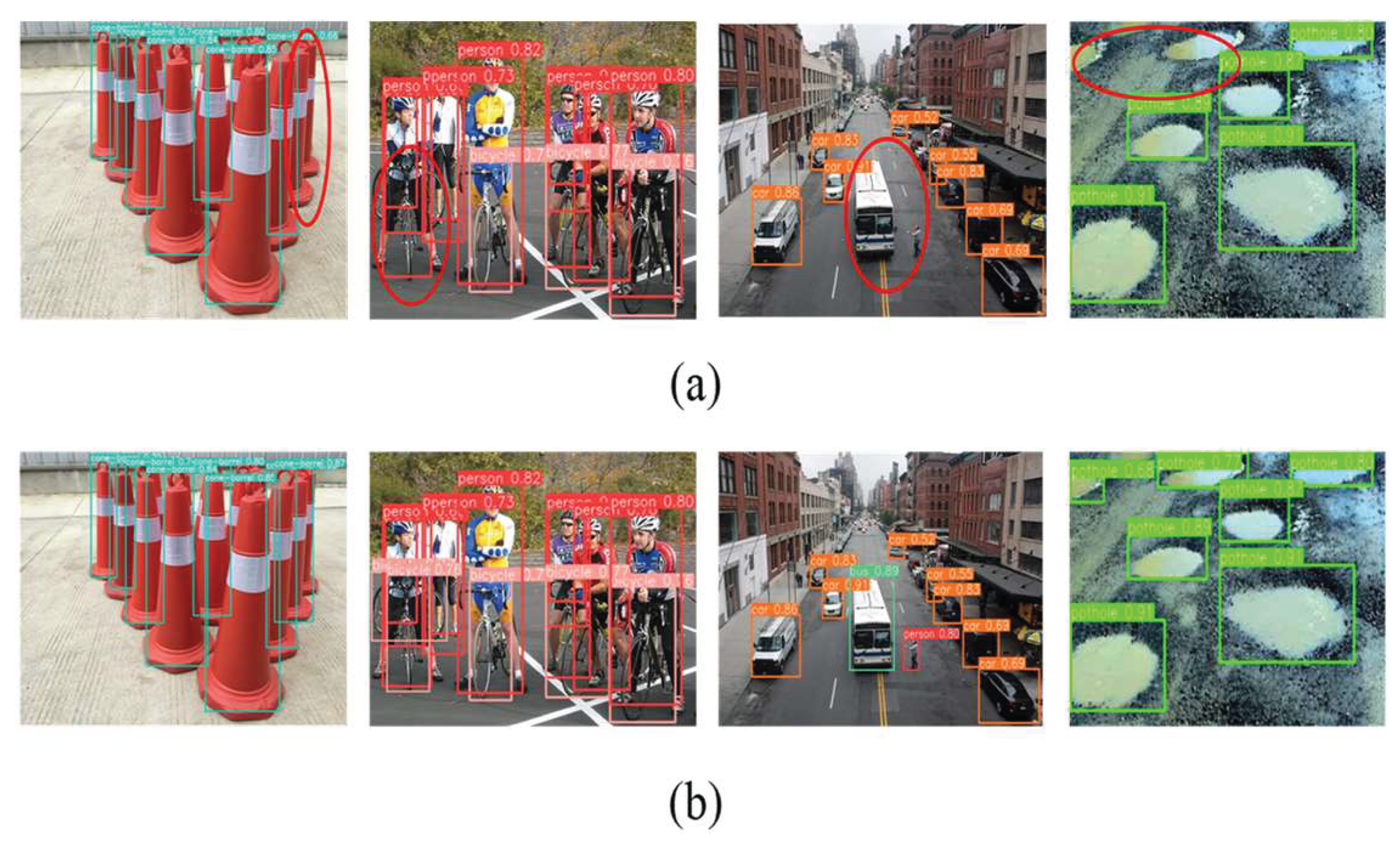
Figure 18.
Direction guidance design.
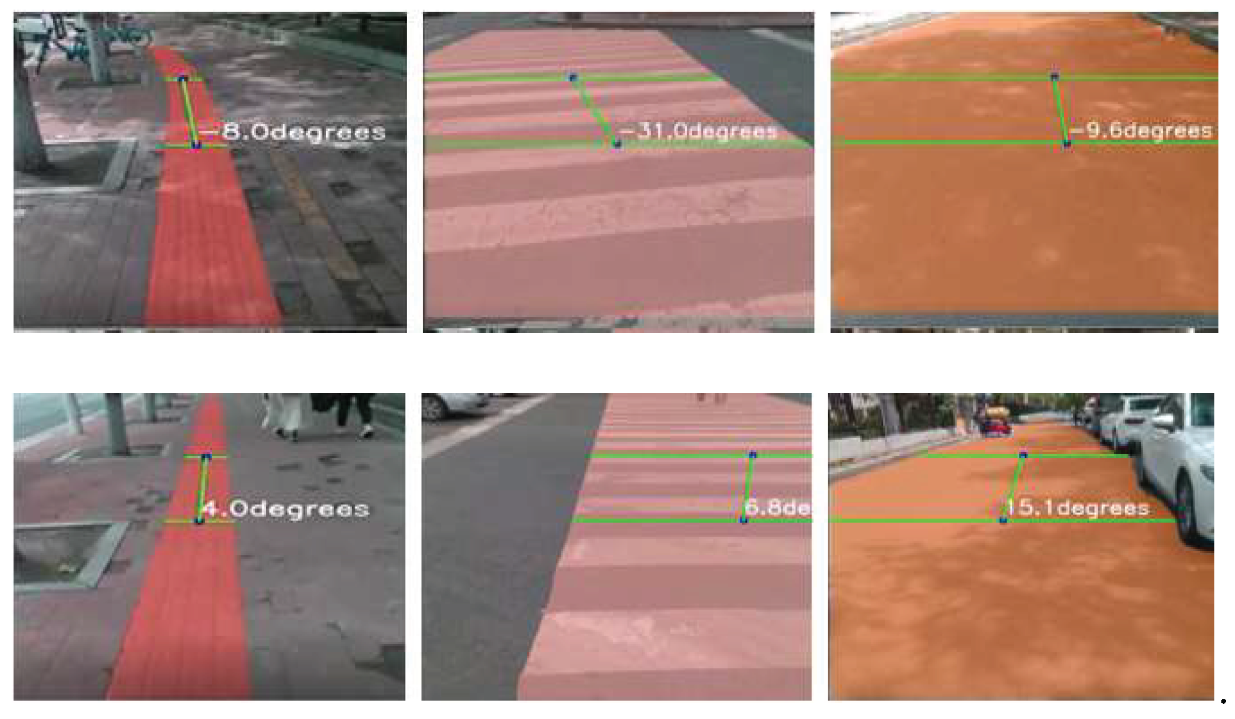
Figure 19.
Obstacle avoidance strategy design.
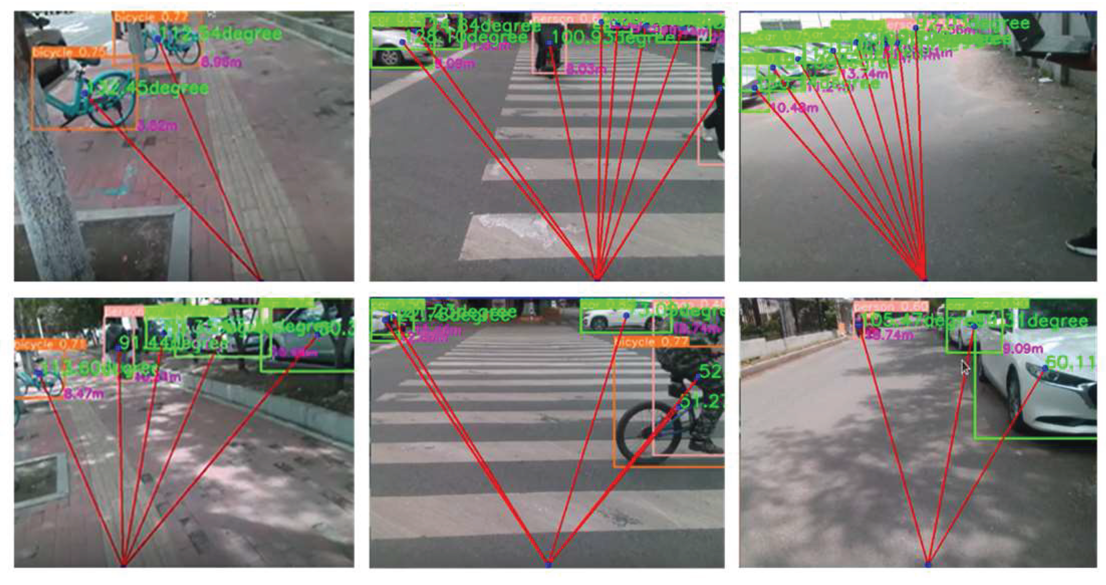
Figure 20.
Test results in different scenarios.
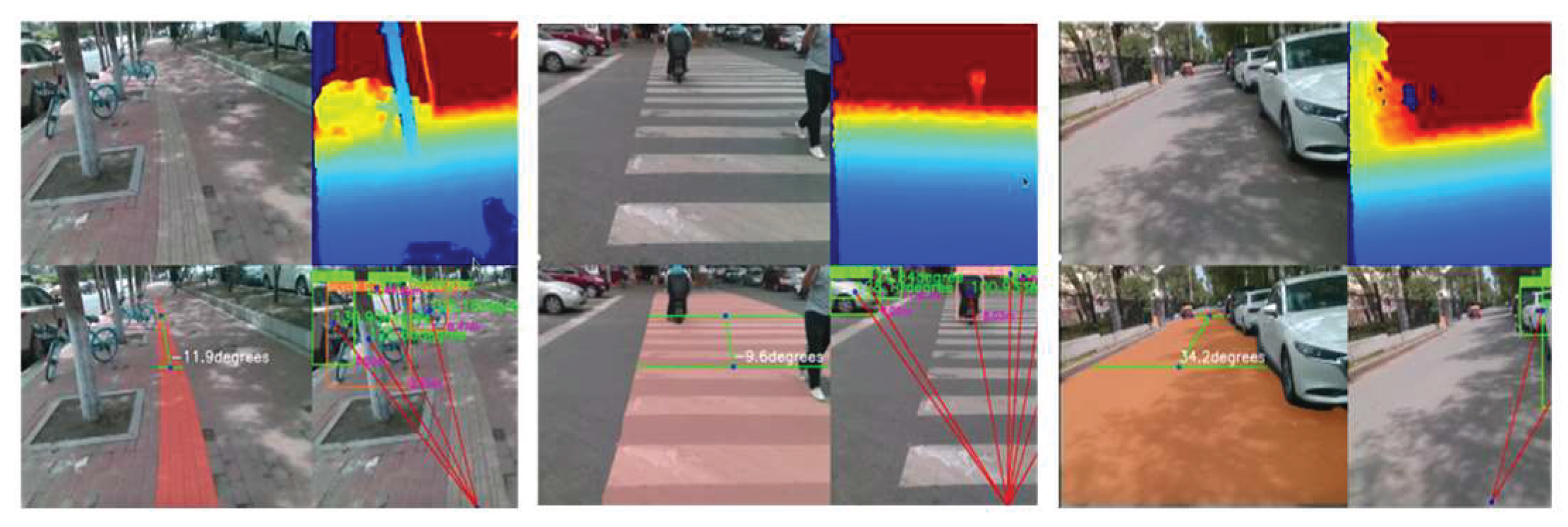

Table 1.
Jetson nano hardware configuration table.
| NVIDIA Jetson nano | |
| GPU | 128-core Maxwell |
| CPU | Quad-core ARM A57 @ 1.43 GHZ |
| memory | 4 GB 64-bit LPDDR4 25.6 GB/s |
| storage | microSD (not included) |
| Video encoding | 4K @ 30|4x 1080p @ 30|9x 720p @ 30 [H.264/H.265) |
| Video decoding | 4K @ 60|2x 4K @ 30|8x 1080p @ 30 [H.264/H.265) |
| camera | 1x MIPI CS1-2 DPHY lanes |
| connectivity | Gigabit Ethernet, M.2 Key E |
| display | HDMI 2.0 and eDP 1.4 |
| USB interface | 4x USB 3.0, USB 2.0 Micro-B |
| other | GPIO, 2C, 2S, SPI. UART |
| Mechanical part | 69 mm x 45 mm, 260-pin edge connector |
Table 2.
Experimental platform configuration.
| Project | Configure |
| Operating System | Ubuntu20.04 |
| Graphics Card | GeForce RTX 3060(12GB) |
| CUDA Version | 11.8 |
| Python | 3.8.16 |
| Deep Learning Framework | Pytorch1.13.1 |
Table 3.
Road segmentation ablation experiment.
| Model | Model size↓ | parameters↓ | GFLOPs↓ | mAPmask↑ | FPS↑ |
|---|---|---|---|---|---|
| Baseline | 6.8 | 3.26 | 12.1 | 0.952 | 67 |
| +MSAFEB | 5.6 | 2.74 | 10.2 | 0.963 | 94 |
| +DSFFM | 6.4 | 3.18 | 11.8 | 0.966 | 85 |
| +ACADSH | 5.9 | 2.96 | 10.5 | 0.961 | 88 |
| +MSAFEB+DSFFM | 5.9 | 2.84 | 10.9 | 0.971 | 95 |
| +MSAFEB+ACADSH | 5.4 | 2.79 | 10.3 | 0.972 | 94 |
| +DSFFH+ACADSH | 6.1 | 3.09 | 11.2 | 0.971 | 90 |
| +MSAFEB+DSFFE+ACADSH | 5.1 | 2.69 | 9.8 | 0.979 | 98 |
Table 4.
Obstacle detection ablation experiment.
| Model | Model size↓ | parameters↓ | GFLOPs↓ | mAP↑ | FPS↑ |
|---|---|---|---|---|---|
| Baseline | 6.3 | 3.01 | 8.2 | 0.726 | 73 |
| +MSAFEB | 5.7 | 2.86 | 7.9 | 0.741 | 93 |
| +DSFFM | 6.2 | 2.97 | 6.7 | 0.732 | 87 |
| +ACADSH | 5.9 | 2.91 | 7.3 | 0.728 | 85 |
| +MSAFEB+DSFFM | 5.4 | 2.64 | 6.5 | 0.749 | 97 |
| +MSAFEB+ACADSH | 5.8 | 2.63 | 7.1 | 0.743 | 95 |
| +DSFFH+ACADSH | 6.0 | 2.81 | 6.9 | 0.741 | 92 |
| +MSAFEB+DSFFE+ACADSH | 5.2 | 2.47 | 6.1 | 0.757 | 98 |
Disclaimer/Publisher’s Note: The statements, opinions and data contained in all publications are solely those of the individual author(s) and contributor(s) and not of MDPI and/or the editor(s). MDPI and/or the editor(s) disclaim responsibility for any injury to people or property resulting from any ideas, methods, instructions or products referred to in the content. |
© 2025 by the authors. Licensee MDPI, Basel, Switzerland. This article is an open access article distributed under the terms and conditions of the Creative Commons Attribution (CC BY) license (http://creativecommons.org/licenses/by/4.0/).
Copyright: This open access article is published under a Creative Commons CC BY 4.0 license, which permit the free download, distribution, and reuse, provided that the author and preprint are cited in any reuse.


