
Submitted:
24 April 2025
Posted:
09 May 2025
You are already at the latest version
Abstract
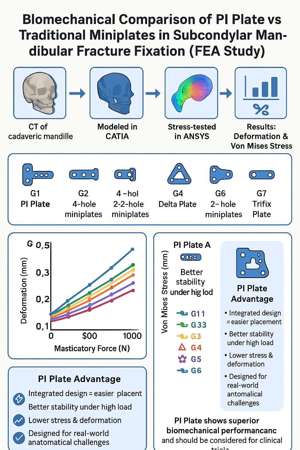
Many types of titanium plates are used to treat subcondylar fracture clinically and the efficacy of fixation in different forces and in different loading conditions has not thoroughly studied. Also, PI-plate is the new innovation which is commercially not available but is design-ready. The primary purpose of this study is to use finite element analysis (FEA) to scrutinize the biomechanical effects of subcondylar fractures fixation with different miniplates so that surgeons get to know the better type of miniplate for fixation to improve overall denoument of treatment.
Keywords:
Subcondylar fractures
; PI-plate
; miniplate
; Finite element Analysis (FEA)
; Deformation
; Von Mises Stress
Introduction
Mandible is known to be the most frequently shattered bone of the maxillofacial region due to motor vehicle accidents, assaults and falls etc. The condylar region is one of the most frequent sites for mandibular fractures. The direction, magnitude, and anatomical and biomechanical characteristics of bone are all factors that might affect fracture of the subcondylar region of the mandible.1 Re-establishment of form and function as soon as possible should be the primary aim of the maxillofacial surgeon. For patients who would normally need intermaxillary fixation, rigid internal fixation can provide stability, lowering the risk of malunion and infection due to postoperative displacement of segments and enhancing quality of life. By definition, subcondylar fractures occur below the point at which the joint capsule is attached, and they typically have no ankylosis. Therefore, in the majority of instances, maxillomandibular fixation is advised to be used for 4 to 6 weeks.2 During the surgical procedure, open reduction with internal fixation may raise the risk of facial nerve injury. However, in fracture patterns with a high degree of displacement, open reduction is frequently required. Numerous kinds of internal fixation for subcondylar fractures have been used, but no consensus have been drawn in the selection of optimum fixation devices.3
Manipulating and adapting two different plates is tedious for the surgeon as there is very little access along with constant concern for the facial nerve. Keeping this in mind we have designed a single unit plate that connects the two separate units and allows for rapid adaptation and fixation with better stability.
This study uses finite element analysis (FEA) to assess scenarios for treatment of subcondylar fracture. Analysis included segmental deformation and Von Mises Stress evaluations of a human cadaveric mandible.
Materials and Methods
A CT scan of a dentate, dry, cadaveric skull was performed using a Wipro Revolution Frontier Gen3 at the NKP Salve Institute of Medical Sciences & Lata Mangeshkar Hospital, Nagpur, India. The DICOM data were imported into CAD (Computer-Aided Design) software, which is essential for creating accurate and detailed 3D models of mechanical systems. These models are vital for visualizing and simulating the physical behaviour of complex structures and components before manufacturing. In the present study, we utilized CATIA V5(Dassault systems) for the initial modelling phase due to its advanced features and robust capabilities in handling intricate designs. CATIA V5 enabled us to accurately represent the geometry and physical properties of the system under investigation.
Following the modelling phase, the prepared models were imported into ANSYS for further analysis. ANSYS (Version 2019 R2) provided a comprehensive platform for performing finite element analysis (FEA), allowing us to evaluate the performance, strength, and durability of the designed components under various conditions. This combined approach ensured a thorough and efficient evaluation process, from initial design to detailed analysis.
To delve deeper into the study, we formed seven distinct groups, each equipped with a mandible fitted with different bracket arrangements. This variation allowed us to investigate the impact of different configurations on the overall performance and stress distribution within the mandible. By analysing these different setups, we aimed to identify the optimal bracket arrangement that offers the best combination of strength and durability. Each group’s mandible model was meticulously created in CATIA V5, incorporating the specific bracket details. Subsequently, these models were subjected to rigorous simulations in ANSYS to assess their structural integrity and behaviour under various load conditions. The insights gained from this comprehensive analysis were invaluable in understanding the nuances of each bracket arrangement, ultimately contributing to the advancement of our study.
A linear static analysis was performed on each model to determine the distribution of von Mises (VM) stress for the relevant plate and screw configurations, as well as the relative movement between the fracture fragments. Comparative analyses of the VM stress distribution and relative displacement between the fractured fragments allow for predicting which configuration is most stable compared to the other plate fixation patterns considered in this study. A lower volume-weighted mean VM stress and lower relative interfragmentary movement are likely to be associated with more stable fixation.
The CAD software combined the mandible with left subcondylar fracture, miniplate, and screws to create seven different FEA computer models where-in Group 1 is "PI" plate; Group 2 included 4 hole continuous miniplate at posterolateral surface of subcondylar fracture and 4 hole continuous miniplate at anterolateral surface; Group 3 included 4 hole continuous miniplate at posterolateral surface of subcondylar fracture and 2 hole miniplate at anterolateral surface of subcondylar fracture; Group 4 included Delta plate, Group 5 included trapezoidal plate, Group 6 included 2 hole miniplate at posterolateral surface and anterolateral surface, Group 7 included Trifix plate.
Loading Conditions and Boundary Conditions
This study was primarily based on previous research. Given the relatively high contralateral occlusal stress in the contralateral occlusion task, the right unilateral molar clench (RMOL) occlusal mode was used in this study. The loading conditions were defined by the external forces exerted by the superficial masseter (SM), deep masseter (DM), medial pterygoid (MP), anterior temporalis (AT), middle temporalis (MT), and posterior temporalis (PT), including the magnitude and direction of these forces.4 [Figure The boundary conditions were established with the temporomandibular condyle set as a fixed end, and the displacements along the X, Y, and Z-axes at this site were set to 0. The right molar was fixed to simulate the tooth's condition during RMOL, representing contact with the right (unilateral) posterior tooth. For the miniplate and screw contact, the miniplate-mandible contact was set to "no separation," allowing only minimal frictionless sliding. The contact at the mandibular condyle oblique fracture site was set to frictional, with a friction coefficient of 0.45.5
Material Properties of the Model
The model consisted of four components: cortical bone, trabecular bone, miniplate, and screws. The material properties for the simulation were sourced from existing literature, and all materials were assumed to be homogeneous, isotropic, and linearly elastic.11 Therefore, two independent parameters—Young’s modulus (E) and Poisson’s ratio (ν)—were used to define the material properties (Table 1). The screws and miniplates were made of 1.5mm thickness titanium alloy, consistent across all groups. 6 Additionally, the finite element analysis (FEA) computer model utilized a 0.5 mm tetrahedral mesh. After performing the convergence test on the meshes, all models met the 5% stop criteria. The FEA observational indicators included the deformation of the miniplate and screws, as well as the von Mises stress on the mandibular bone, miniplates, and screws.7
Results
The distribution of von Mises stress throughout the overall structure, the reaction force at the left and right fixed ends of the TMJ, and the deformation of the miniplates and screws were determined using FEA (Table 2 & Table 3).8
As we can see that in Table 2, the least deformation in overall plate structure was least in group 1 i.e. PI plate. The deformation in every group ranged between 0.010 – 0.019 mm. At 400N and 500N of forces, Group 2 was least deformed. But at the greatest force i.e. 1000N, group 1 again surpassed every group and was the minimally deformed.
Figure 1 shows the magnitude and forces in right and left TMJ under loading conditions. Deformation and Von mises stresses were studied at 132N, 200N, 300N, 400N, 500N, 600N, 700N, 800N, 900N and 1000N.
Figure 2 shows the deformation of plates (in mm). From Fig 2, we interpret that minimum deformation is taking place near the fracture region. Though there are numerical differences which can be seen in Table 1.1.
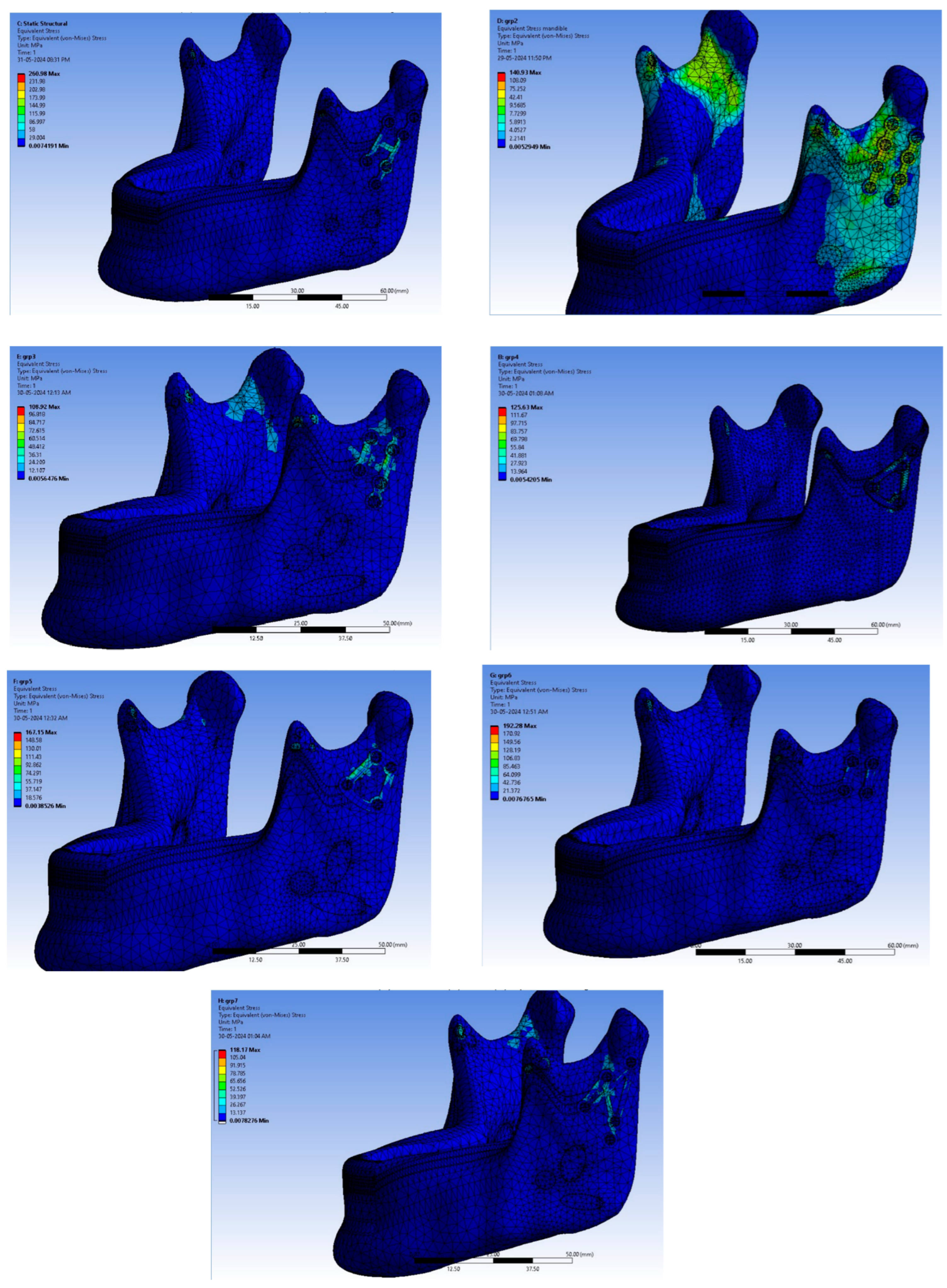
Figure 3 shows the Von mises stress (in mm) acting in every group. Table 3 shows Von mises stress in each group and it is concluded that at 132N group 1 was under the least stress. But, these results weren’t same at different masticatory sorces. At 300N of masticatory forces, group 4 was the least to exhibit forces. But at maximum 1000N of masticatory forces, again group 1 was under the least Von mises stress. So, to summarize, Group 1 performed par excellence tests and is quite comparable to other miniplates which are already commercialized.
Discussion
Using miniplate fixation for sub-condylar fractures has become a widely accepted clinical practice, with generally favourable outcomes. While some studies have explored the effectiveness of miniplate fixation, most mechanical analyses have not taken into account the impact of different masticatory forces. Additionally, these mechanical analysis can be quite complex.9,10, 4 Therefore, this study utilized finite element analysis (FEA) to successfully examine the biomechanics of various miniplate fixation at various forces. The findings provide valuable insights for surgeons into the effects of this type of fixation.
In the finite element analysis (FEA), the reaction force at the fixed end of the temporomandibular joint (TMJ) was observed due to the chosen boundary conditions. When the mandible is unaffected by a subcondylar fracture, a relatively high reaction force is generated in the contralateral TMJ under right molar occlusion loading (RMOL).11
This condition is consistent with the mandible's real-world function, suggesting that mastication should be avoided during healing period. An unhealed fracture may cause increased stress disturbances around the fracture line, potentially disrupting the healing process.12
It is found through clinical experience that, due to space constraints, it can sometimes be challenging to position two straight plates in an optimal arrangement. Hence, author has designed the PI plate (group 1). Manipulating and adapting two different plates is tedious for the surgeon as there is very little access along with constant concern for the facial nerve. Keeping this in mind we have designed a single unit plate that connects the two separate units. This allows the advantages of rapid adaptation and fixation along with good stability which would lead to reduced operating time, optimal surgical outcome, lesser morbidities.
PI plates have been designed with Two vertically oriented plates, One four hole with gap and another 2 hole with gap are joined together with a horizontal bar or strut in the middle. PI plate is designed as Right and left because longer plate i.e. four hole with gap is to be adapted to lateral border of condyle where the tension (torsional) force is maximum and to counter rotational forces of condylar fracture another two hole with gap plate is adapted and joined together with a horizontal bar or strut in middle.
To justify, two straight plates provides very rigid internal fixation in low-neck/sub condylar fracture but with certain anatomical limitations it is not always possible to place two plates at the fracture site. The connecting horizontal bar/ strut has been thought to possess robust mass that contributes to dissipation of forces and resistance to fracture of plate.
A study by P Aquilina et al (2014) examined the stability of three different patterns of plate fixation for mandibular condyle fractures using commercially pure titanium implants. Finite element models simulating a mandibular condyle fracture were created, featuring heterogeneous bone material properties and simulated jaw musculature. The results showed that the 1.5-mm X-shaped plate was the most stable among the three configurations tested and performed similarly to a 2.0-mm straight four-hole plate. The study does not support using rectangular or square plate patterns for these fractures but suggests that a 1.5-mm X plate may be suitable in specific cases.12
Chao Min-Huang et al (2021) in their study also concluded that miniplate fixation which was placed closer to the posterior margin, could effectively reduce the amount of sliding distance in the fracture site, thereby achieving greater stability. In PI plate (group 1), the longer plate is adapted at posterolateral surface to overcome torsional forces and to provide higher stability as the muscle forces in this area are very intense.11
This concludes that PI plate has overcome many disadvantages which surgeons has been experiencing with other commercially available miniplates. Further study on patients should be carried out using PI plate (group 1). For that to happen, we are currently focusing to make PI plate commercially available so that a study on patients will be more pragmatic.
References
- Bormann K-H, Wild S, Gellrich N-C, Kokemüller H, Stühmer C, Schm- elzeisen R, Schön R. Five-year retrospective study of mandibular fractures in Freiburg, Germany: incidence, etiology, treatment, and complications. J Oral Maxillofac Surg. 2009;67:1251–5. [CrossRef]
- Worsaae N, Thorn JJ. Surgical versus nonsurgical treatment of unilateral dislocated low subcondylar fractures: a clinical study of 52 cases. J Oral Maxillofac Surg. 1994;52:353–60. [CrossRef]
- Çimen E, Önder ME, Cambazoglu M, Birant E. Comparison of diferent fxation types used in unilateral mandibular condylar fractures: an in vivo study with new biomechanical model. J Craniofac Surg. 2016;27:1277–81.
- Kozakiewicz M, Swiniarski J. “A” shape plate for open rigid internal fxation of mandible condyle neck fracture. J Craniomaxillofac Surg. 2014;42:730–7.
- Lee HH. Finite element simulations with ANSYS workbench 15, Chuan Hwa Book Co. 2014.
- Parr WCH, Wroe S, Chamoli U, et al. Toward integration of geometric morphometrics and computational biomechanics: new methods for 3D virtual reconstruction and quantitative analysis of finite element models. J Theor Biol 2012;301: 1–14. [CrossRef]
- Hijazi L, Hejazi W, Darwich MA, Darwich K. Finite element analysis of stress distribution on the mandible and condylar fracture osteosynthesis during various clenching tasks. Oral maxillofac surg. 2016;20:359–67. [CrossRef]
- Aquilina P, Chamoli U, Parr WCH, Clausen PD, Wroe S. Finite element analysis of three patterns of internal fixation of fractures of the mandibular condyle. Br J Oral Maxillofac Surg 2013;51(4): 326–331. [CrossRef]
- Alkan A, Metin M, Muğlali M, Ozden B, Celebi N. Biomechanical comparison of plating techniques for fractures of the mandibular condyle. Br J Oral Maxillofac Surg 2007;45(2):145–149. [CrossRef]
- Pilling E, Eckelt U, Loukota R, Schneider K, Stadlinger B. Comparative evaluation of ten different condylar base fracture osteosynthesis techniques. Br J Oral Maxillofac Surg 2010;48(7):527–531. [CrossRef]
- Huang CM, Chan MY, Hsu JT, Su KC. Biomechanical analysis of subcondylar fracture fixation using miniplates at different positions and of different lengths. BMC Oral Health. 2021 Oct 21;21(1):543. PMID: 34674692; PMCID: PMC8532336. [CrossRef]
- Aquilina P, Parr WC, Chamoli U, Wroe S, Clausen P. A Biomechanical Comparison of Three 1.5-mm Plate and Screw Configurations and a Single 2.0-mm Plate for Internal Fixation of a Mandibular Condylar Fracture. Craniomaxillofac Trauma Reconstr. 2014 Sep;7(3):218-23. Epub 2014 Apr 18. PMID: 25136411. [CrossRef]
Figure 1.
Magnitude and direction of forces in left and right TMJ in each group.
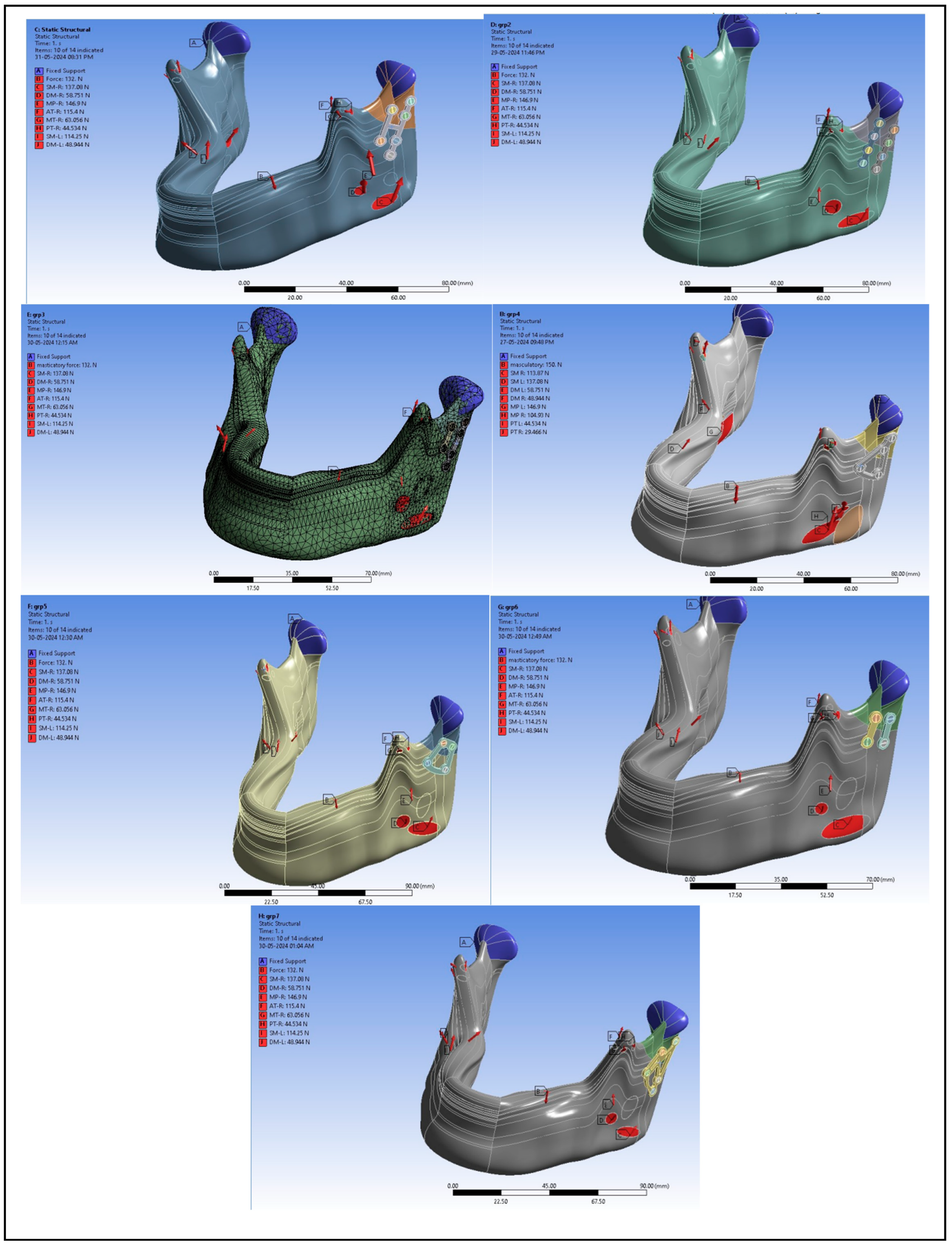
Figure 2.
Total Deformation on overall structure of mandibular bone in all groups.
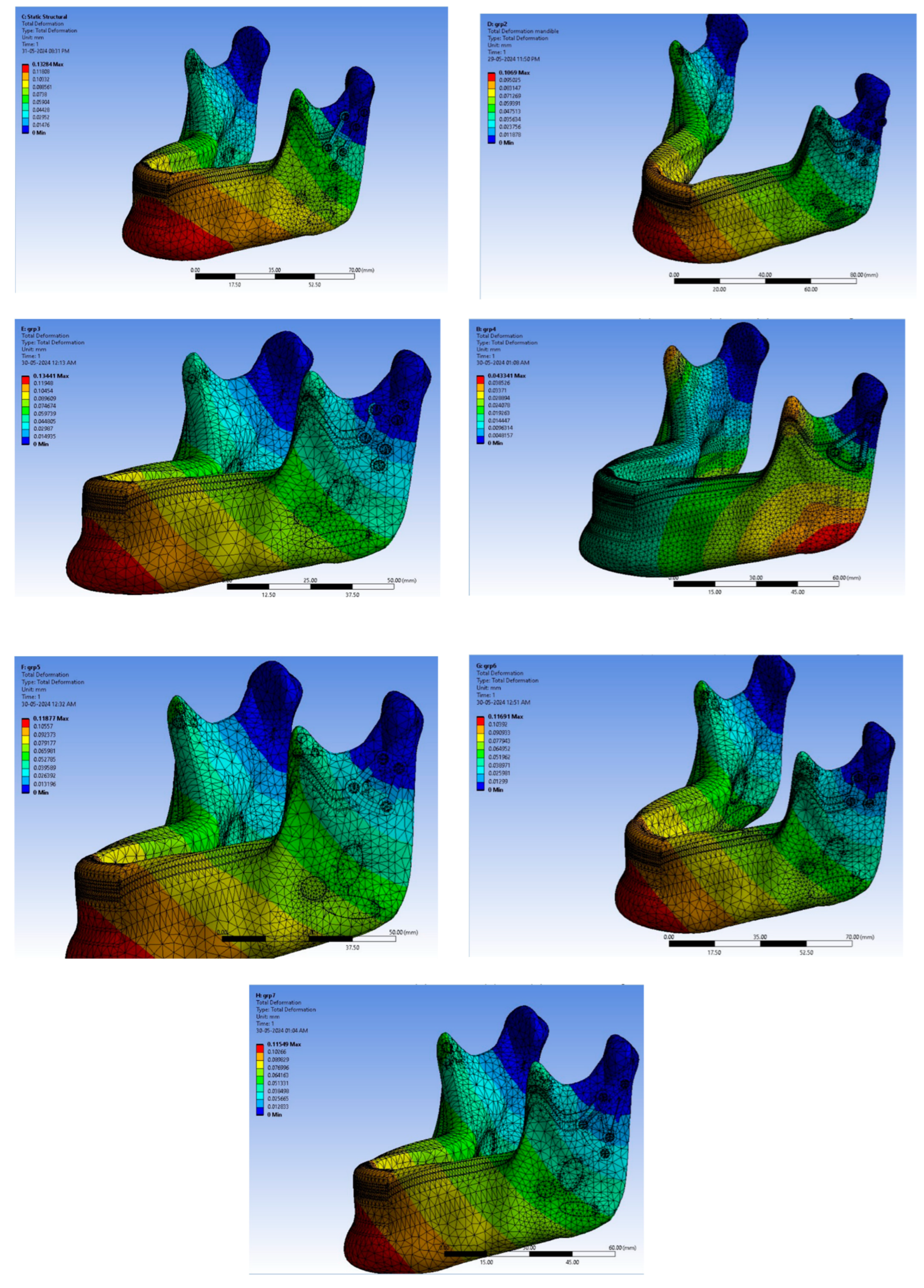
Figure 3.
Von Mises stress on overall mandibular structure in every group.

| Sr. no. |
Component | Material used | Young’s Modulus (Mpa) | Poisson’s Ratio |
| 1 | Trabecular bone | 1000 | 0.3 | |
| 2 | Cortical Bone | 17000 | 0.3 | |
| 3 | Miniplate | Titanium Alloy | 110000 | 0.3 |
| 4 | Screw | Titanium Alloy | 118000 | 0.3 |
| Deformations in plates (in mm) | ||||||||
|---|---|---|---|---|---|---|---|---|
| Masticatory force | Group 1 | Group 2 | Group 3 | Group 4 | Group 5 | Group 6 | Group 7 | |
| 132 | 0.010312 | 0.015011 | 0.017577 | 0.012384 | 0.019248 | 0.013155 | 0.015419 | |
| 200 | 0.004354 | 0.008226 | 0.008222 | 0.005234 | 0.008185 | 0.005215 | 0.004834 | |
| 300 | 0.008533 | 0.005286 | 0.007056 | 0.01038 | 0.009114 | 0.007781 | 0.014383 | |
| 400 | 0.018573 | 0.015023 | 0.020703 | 0.022096 | 0.025493 | 0.019709 | 0.03139 | |
| 500 | 0.028873 | 0.025647 | 0.03468 | 0.03419 | 0.042031 | 0.031783 | 0.048543 | |
| 600 | 0.03923 | 0.036379 | 0.048723 | 0.046405 | 0.058596 | 0.043886 | 0.065728 | |
| 700 | 0.049611 | 0.047145 | 0.062787 | 0.058672 | 0.07517 | 0.056 | 0.082925 | |
| 800 | 0.060003 | 0.057927 | 0.076859 | 0.070965 | 0.091748 | 0.068118 | 0.100128 | |
| 900 | 0.070402 | 0.068718 | 0.090937 | 0.083272 | 0.108329 | 0.080239 | 0.117334 | |
| 1000 | 0.0750804 | 0.079513 | 0.105017 | 0.095587 | 0.124911 | 0.092362 | 0.134542 | |
| Stresses in every group (in mm) | |||||||
|---|---|---|---|---|---|---|---|
| Masticatory force (N) | Group 1 | Group 2 | Group 3 | Group 4 | Group 5 | Group 6 | Group 7 |
| 132 | 7.653 | 17.011 | 14.628 | 9.273 | 22.550 | 9.529 | 15.322 |
| 200 | 6.236 | 12.160 | 9.469 | 5.930 | 11.005 | 4.679 | 9.152 |
| 300 | 6.636 | 8.309 | 6.478 | 5.051 | 10.057 | 6.080 | 16.850 |
| 400 | 8.869 | 14.732 | 12.602 | 9.869 | 27.572 | 13.657 | 31.151 |
| 500 | 11.649 | 23.136 | 20.809 | 15.723 | 45.730 | 21.693 | 46.096 |
| 600 | 14.702 | 31.995 | 29.571 | 21.791 | 63.980 | 29.830 | 61.242 |
| 700 | 17.974 | 41.040 | 38.486 | 27.935 | 82.263 | 38.004 | 76.481 |
| 800 | 21.379 | 50.181 | 47.460 | 34.114 | 100.561 | 46.196 | 91.769 |
| 900 | 24.867 | 59.381 | 56.465 | 40.312 | 118.867 | 54.397 | 107.086 |
| 1000 | 28.408 | 68.621 | 65.487 | 46.522 | 137.178 | 62.605 | 122.422 |
Disclaimer/Publisher’s Note: The statements, opinions and data contained in all publications are solely those of the individual author(s) and contributor(s) and not of MDPI and/or the editor(s). MDPI and/or the editor(s) disclaim responsibility for any injury to people or property resulting from any ideas, methods, instructions or products referred to in the content. |
© 2025 by the authors. Licensee MDPI, Basel, Switzerland. This article is an open access article distributed under the terms and conditions of the Creative Commons Attribution (CC BY) license (http://creativecommons.org/licenses/by/4.0/).
Copyright: This open access article is published under a Creative Commons CC BY 4.0 license, which permit the free download, distribution, and reuse, provided that the author and preprint are cited in any reuse.


