Submitted:
28 April 2025
Posted:
29 April 2025
You are already at the latest version
Abstract
This paper presents an innovative approach to embedded deformation measurement in cement-based matrices using distributed fiber optic sensors (DFOS). The first 24 hours after casting is a complex and dynamic process that has a significant impact on the subsequent quality, performance and durability of the material. Traditional deformation measurement techniques have limitations, particularly in terms of spatial resolution, variation or interruption of the hydration process. In this study, the suitability of Rayleigh scattering based DFOS for the detection of early deformation in mortars was evaluated. Experiments were performed at standardized prisms according to EN 196, using both uncoated (UCF) and ORMOCER® coated fibers (OCF). The measurements were performed under controlled environmental conditions with full temperature and humidity compensation. The results show a high reproducibility with low variation of the measured values at different samples. A negative deformation was observed after the first two hours. This was followed by expansion, which may be related to ettringite formation, thermal expansion, reabsorption of bleeding water and hydration discussed in the literature. These observations are in agreement with recent hydration models which assume a fundamentally expansive hydration process. The study demonstrates the suitability of DFOS technology for accurate and reliable measurements of early deformation in cement matrices. The continuous monitoring of concrete components over their entire life cycle opens up new possibilities for the optimization of concrete structures and contributes to a better understanding of the complex early deformations, including cracking or the influence of reinforcement.
Keywords:
early deformation measurement
; cement-based materials
; distributed fiber optic sensors
; temperature and moisture compensation
and uncomment
1. Introduction
In recent decades, fiber optic sensors (FOS) have become established as versatile and powerful measuring instruments in a variety of applications. This innovative technology is based on the detection of changes in light through thin, flexible glass fibers that enable strain or temperature measurement. In particular, distributed measurement systems (DFOS), which allow spatially resolved measurements along the fiber, offer significant advantages over point-based measurement systems [1,2]. The range of potential applications is broad and extends beyond the initial domains of telecommunications to various sectors such as automotive, aerospace, energy, medical and construction. In civil engineering, especially in the context of Structural Health Monitoring (SHM), FOS represents a viable solution for continuous and long-term monitoring of structures [3,4,5,6]. The ability to record deformations, vibrations, temperature changes and other critical parameters in real time is invaluable in ensuring the safety and maintenance of bridges, high-rise buildings, tunnels and various other infrastructure facilities, tunnels and various other infrastructure facilities [7,8,9,10,11,12,13,14,15,16,17,18,19,20]. The advantages of this technology are its high sensitivity, the possibility of distributed measurements over long distances, its insensitivity to electromagnetic interference and its ability to operate reliably even under extreme conditions. A FOS is characterized by its small dimensions and its ability to measure over distances of several kilometers with minimal loss of measurement characteristics. This attribute enables the measurement of large areas of component surfaces or building material matrices, making it an attractive alternative for a wide range of applications [21]. Advances in photonics and materials science continue to expand the applications of FOS and open new perspectives for precise measurement and monitoring in complex environments such as cementitious matrices [22,23,24,25].
The deformation of cement-based matrices within the first 24 hours after casting is a complex and dynamic process influenced by numerous interrelated factors [26]. This early phase, also known as early age, has a significant impact on the subsequent quality, performance and durability of the material [27,28,29]. During this critical phase, the cement paste undergoes a series of physical and chemical transitions that can result in significant volume changes. These changes can be attributed to several mechanisms, including chemical shrinkage, autogenous shrinkage, plastic shrinkage, and thermal deformation [30]. Chemical shrinkage is defined as the decrease in volume of the hydration products relative to the original materials. Autogenous shrinkage is the result of self-drying of the cement matrix. Plastic shrinkage occurs when water on the surface evaporates at a rate that cannot be replenished by bleeding. Thermal deformation is caused by the exothermic nature of the hydration reactions and subsequent cooling.
With the exception of evaporation, the deformation mechanisms in cementitious matrices are largely due to hydration of the cement particles. Although cement hydration has been the subject of research for over a century, the precise mechanisms are still not fully understood [31]. Hydration models can be used for validation, especially for the evaluation of deformation measurements. The development of these models is largely based on the “crystalloid theory” of Le Chatelier and the “colloid theory” of Michaelis [32,33]. According to both theories, the hydrated cement in the form of nanopowder is assumed to have a smaller volume than the anhydrous cement and the water required to hydrate the cement. As a result, volume contraction is always assumed under appropriate environmental conditions. This principle was further elaborated in a model described by Powers in the 1960s, which could explain the expansion of cement pastes that begins after the dormant phase [31,34]. In recent decades, other hydration models have been developed to provide a more detailed description of the complex chemical and physical processes during cement hydration [31,35,36]. In [37] it was postulated that the hydration is largely expansive due to the growing neighboring C-S-H shells pushing away, which contradicts earlier assumptions. They assume that under constant pore moisture and sufficient growth of the pore volume, the hydrated cement will always expand, even if the total volume shrinks. In the initial phase, the growth of ettringite crystals can potentially mask this effect [38]. In later phases, however, the crystals should no longer affect self-deformation. In addition, reabsorption of bleeding water and, in general, thermal expansion of the material are associated with swelling in the literature [39,40,41]. This suggests that there are still uncertainties, especially regarding the early stages of hydration and the precise mechanisms leading to deformation [31].
The complexity of the process is further accentuated by the dependence of the hydration and the resulting deformation mechanisms on the ambient conditions and the components of the mixture [42,43]. This dependence leads to significant challenges in the reproducible measurement of deformations or volume changes. Furthermore, the majority of deformation measurement methods are dependent on ambient conditions, especially temperature and humidity [39].
A variety of methods have been developed and used to measure the early deformation of cementitious materials [39,44]. Each method has specific advantages and disadvantages. To improve the comparability and presentation of these methods, a systematic categorization is proposed. Kurup et al. present a classification system that distinguishes between contact and non-contact methods [45]. This study introduces a modified categorization that incorporates the directional dependency of the methods, allowing for a more comprehensive comparison (Figure 1). Table 1 provides a summary of the various measurement techniques used to obtain deformation data, with a particular focus on measurements made during the first 24 hours after casting.
Volumetric methods (e.g. buoyancy method) are based on measuring the change in volume by determining the change in weight of a sample immersed in liquid according to Archimedes’ principle [58,59]. In this method, the sample is immersed in a non-reactive medium (e.g. paraffin oil) to minimize the influence of water exchange and bleeding effects. The change in weight is directly related to the volume contraction of the sample. Critical aspects of this method arise particularly with regard to bleeding effects when water is used as the immersion medium [59]. The use of paraffin oil can reduce this effect. Furthermore, temperature stability is a critical measurement factor as the density of the immersion medium is temperature dependent [58]. Finally, the method is dependent on sample geometry, which limits its applicability to real structures.
Linear deformation methods are among the established methods for detecting early deformation in cementitious matrices. Unidirectional external measurement methods include the corrugated tube method according to ASTM C 1698, in which a flexible corrugated tube is filled with the mortar matrix and its change in length is measured with displacement transducers [41,60]. A comparable method, the Plastic Sleeve Test (PST), replaces the corrugated tube with smooth plastic sleeves to reduce friction effects [49]. Both methods allow standardized control of boundary conditions, but are limited to one-dimensional measurements. Critical aspects to be considered are the influence of the tube geometry on the freedom of deformation of the matrix, difficulties in compacting the material, and possible artifacts caused by bleed water that may accumulate at the sample/tube interface. Similar limitations apply to the shrinkage channel, another horizontal measurement method that detects linear deformations via mechanical displacement transducers at the sample cross section [55]. The use of neoprene inserts between the mold wall and the matrix can reduce the influence on the freedom of deformation. Non-contact alternatives can be laser-optical or photo-optical methods [29,48]. The latter, such as digital image correlation (DIC) and digital image processing (DIP), offer the possibility to visualize deformation fields at the matrix surface. These methods can also capture spatial strain patterns and are suitable for complex sample geometries [48]. However, they are limited to visible, textured surfaces and are susceptible to interference from bleeding water, which alters light reflection and can lead to high scattering. In addition, optical methods only measure surface strain and do not account for volumetric effects within the sample.
Integrated sensors offer the possibility to measure deformations directly in the cement matrix. Strain gages embedded in the matrix measure local strains with high accuracy, but due to their size and stiffness they can influence the deformation behavior of the surrounding microstructure [54]. In addition, strain gages are limited to point measurements and require temperature compensation [53]. FOS, which have diameters of only 125 μm to 250 μm and therefore hardly disturb the hydration process [50], are an advantageous alternative. Fiber Bragg Grating (FBG) sensors provide highly sensitive strain measurements at discrete points along the fiber [50,51]. They also allow simultaneous measurement of temperature and strain, which can be used to compensate for thermal effects within the matrix. However, FBGs are also limited to discrete measurement points. DFOS overcomes this limitation by providing continuous measurements along the entire fiber length [22]. With spatial resolutions down to 1mm, they capture not only local strain peaks but also deformation gradients, which are crucial for the analysis of cracks or structural inhomogeneities [1]. A critical aspect of integrated methods is the time of strain transfer between the sensor and the solidifying matrix. Slowik et al. showed in [50] that a sufficient bond between an FBG sensor and the surrounding matrix already exists after six hours.
The shrinkage cone is a method, which in the context of this study was assigned to the “special” methods (Figure 1). In this method, a cone-shaped mold is used, the vertical change in length of which is measured without contact by means of laser distance measurement [56,57]. The method is characterized by simple handling, but does not allow a direct distinction between different causes of deformation, such as settlement, the influence of gravity and structural deformation [55]. Another challenge is to achieve controlled sample coverage to minimize evaporation effects. Scattering can occur, especially with matrices that tend to bleed excessively, because water deposited on the surface changes the laser reflection properties or the reflector plate floats.
The methods presented in this work and the significant challenges they face, in particular the high scatter of measured values documented in the literature, illustrate the scientific relevance of developing a method for the phase immediately after water addition and beyond [39,41,44,61]. DFOS is a promising method for this purpose. Unlike the alternative methods presented, it offers flexibility in terms of sample geometry or shape, storage type, or composition, allowing multimodal deformation mechanisms to be captured. This allows not only research applications, but also the holistic monitoring of precast or in-situ concrete structures, such as bridges or tunnels.
Despite the advantages described, DFOS also places complex demands on the methodology. One critical aspect is temperature compensation, especially due to temperature changes caused by hydration processes. Depending on the FOS used, temperature changes affect the measurement result. For small laboratory samples, compensation can be simplified by using electrical temperature measurement. For larger components and inhomogeneous temperature profiles, temperature compensation via a decoupled reference fiber is required. Another consideration is moisture compensation. Polymer coatings have a tendency to interact with ambient humidity and its accompanying substances, which can lead to parasitic strains [62]. The aforementioned connection between the matrix and the sensor is another challenge that affects not only the time at which the strain is transmitted, but also its sensitivity. In this context, the following influences on strain transfer must be considered [63,64,65,66,67]. Since the deformations are measured only in the fiber core, all layers between the fiber core and the matrix can be a potential source of strain reduction (Figure 2a). Furthermore, it is not yet known if and to what extent an interfacial transition zone (ITZ) between the matrix and the FOS can reduce the measured deformations (Figure 2b).
The aim of the present study is to evaluate the suitability of Rayleigh scattering based DFOS for the detection of early deformation in mortars. In addition to temperature compensation, humidity compensation was performed according to [62]. Furthermore, uncoated reference fibers were used to distinguish them from artifacts. The experimental design is based on the procedure according to EN 12390-3. The measurements are discussed in the context of current hydration models and comparative measurement methods.
2. Experimental Program
2.1. Experimental Design
In order to evaluate the suitability of DFOS for the measurement of early deformation in cementitious matrices, a test setup according to EN 196-1:2016 with standard prisms was developed. The measurements were performed with the ODiSI-B system from Luna [68] with a spatial resolution of 2.6 mm. Strain values were recorded at a frequency of 1 for 5 seconds every 10 minutes immediately after casting. The FOS were placed in the center of the specimen as shown in Figure 3. To protect the FOS from damage and to reduce possible tensile stress on them during casting, 24G cannula needles were integrated 10 mm deep into the matrix between the formwork and the matrix (Figure 3). An electrical temperature sensor (TSic 506F [69]) placed in the center of the specimen was used in an exclusive series of tests (Figure 7) to compensate for temperature and to investigate thermal expansion. The effect of humidity on the coating was compensated by taking into account the results of [62].
As part of the experimental investigations, a procedure was developed to accurately and reproducibly measure deformations in cementitious matrices using DFOS. The preparation of the experiments included the following steps:
- The mold and FOS were cleaned with isopropyl alcohol. The purpose of this step is to remove contaminants such as oils, release agents, or dust particles that may weaken the bond to ensure optimal adhesion between the matrix and the sensor for improved measurement accuracy.
- The FOS was fixed in the mold using cannula needles (24G). The needles are used to protect the FOS, especially in the zone between the matrix and the mold, and to ensure safe repositioning between and after compacting using the shock table.
- FOS assembly with pigtail and termination.
- The mold with the FOS, the mix components (cement, deionized water and CEN standard sand according to EN 196-1:2016), the mixer including trough and agitator, and the shock table were stored for 24 under controlled environmental conditions (20 °C, 65% rH). This ensured stabilization of the initial conditions before the start of the experiment.
- Before the mortar was applied, the FOS was tared to eliminate any offsets.
- The mortar has been prepared in accordance with the requirements of EN 196-1:2016.
- To avoid damaging the sensor or changing its position, the first layer of the mortar was carefully placed in the mold.
- After filling the first and second layers, the position of the sensor was checked by briefly tightening it. The two layers of mortar were compacted by 60 impacts each on a shock table according to EN 196–1:2016.
- The filled mold was placed on a roller track and covered with a polytetrafluoroethylene (PTFE) sheet to prevent the mortar from drying.
- Start of measurement nine minutes after mbegin of mixing with a duration of 24 and recording of five readings at a rate of 1 every ten minutes.
Figure 5.
Chronology of the experiments.
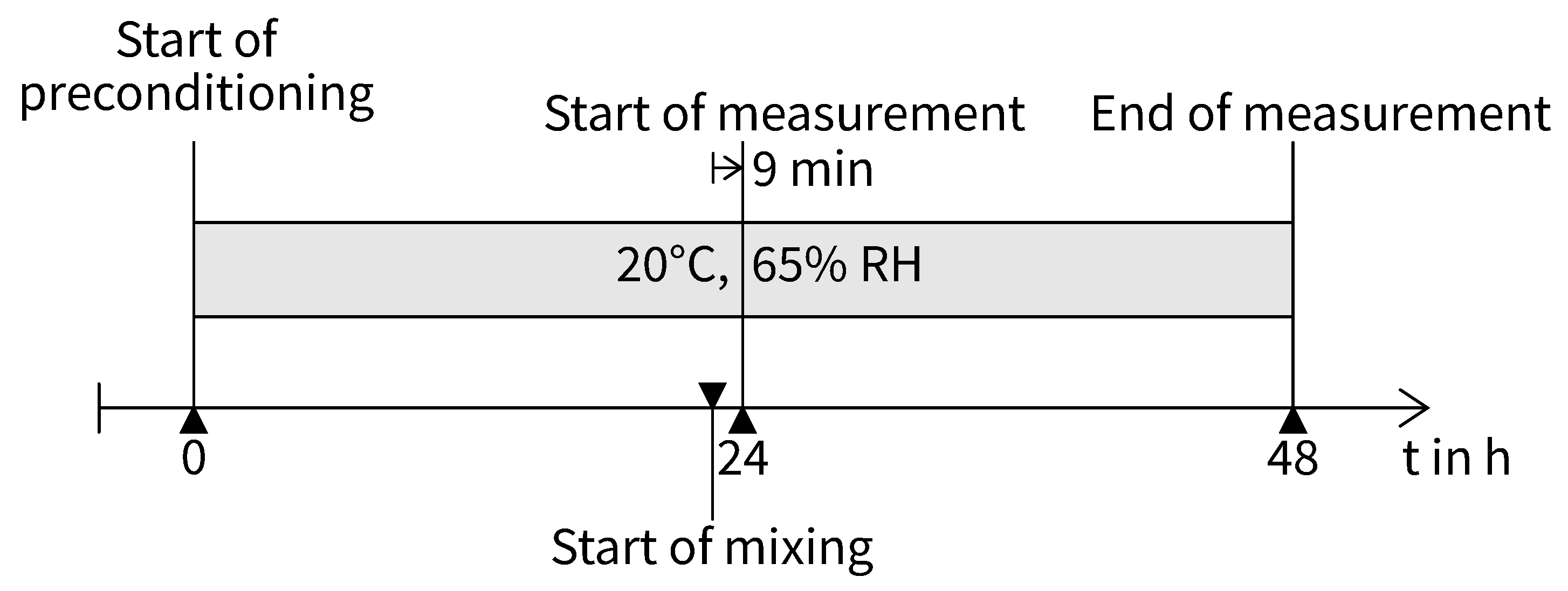
Conditioning of the specimens before and during testing was performed in a constant climate chamber. Storage was in a circulating air environment with extremely low temperature and humidity variations. The average temperature for all samples was = 20.00 °C ( = 0.03 ). The average relative humidity was = 65.3 ( = 1.1).
2.2. Mortar Mixture, Application Material and Fiber Types
A mortar based on CEM I 42.5 R [70] was used as the cementitious matrix for the investigations (Table 2). The mortar was produced with a water to cement (w/c) ratio of 0.5. To minimize the influence of different aggregates and to ensure reproducibility, CEN standard sand according to EN 196–1:2016 was used. The mortar was prepared in a mixer according to EN 196-1:2016. After being placed in the mold, the sample was covered with a PTFE sheet of 1 mm thickness to prevent drying and to ensure controlled hydration conditions. In addition, a test was performed on an uncovered specimen to investigate the effect of reabsorption of bleeding water.
FOS with an ORMOCER® coating (OCF) were used in this investigation [71]. This coating, a material based on organically modified ceramics, protects the glass fiber while allowing high strain transfer from the surrounding matrix to the sensor [22]. An uncoated SMF-28 fiber (UCF) was used as a reference, but its installation in the mold proved to be complex due to its fragile behavior. The characteristics of the FOS used are listed in Table 3. An important aspect of the investigation was to compare the influence of moisture on the OCF with the UCF and the associated moisture compensation. The FOS used have a diameter of 195 and 125 , which minimizes the influence of the sensors on the hydration behavior. The description of the sample variations can be found in Table 4.
3. Results
3.1. Processing of Measurement Results
The deformation values obtained from the measurements require processing since the DFOS provides both time continuous and spatially resolved measurements along the fiber. The processing of the data was performed according to [23] and takes into account the half gauge length required for the region of total strain transfer (ROTST) [63,64,65,66,67]. Due to the plastic and semi-rigid consistency of the matrix in the first hours after mixing, the region of analysis (ROA) was reduced to specimen length to minimize distortions due to incomplete strain transfer. For evaluation, an average was calculated from five measurements taken at a rate of 1 every 10 minutes in ROA (Figure 6). The resulting mean value for each ROA at time was plotted as a single value in the time deformation curves (Figure 8, Figure 9, Figure 10 and Figure 11).
3.2. Compensation for Temperature Effects
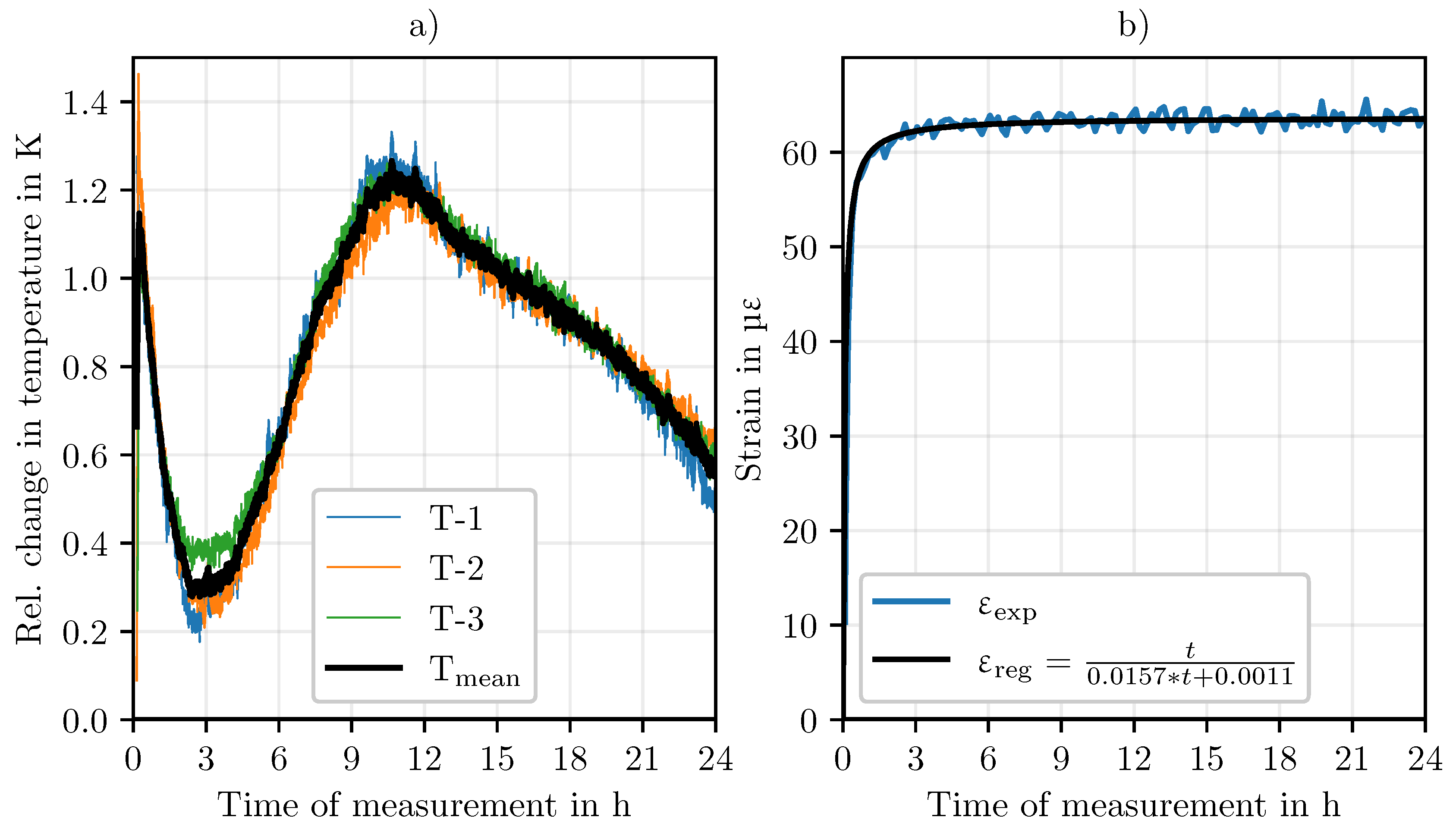
Hydration causes temperature changes in cement-based matrices and embedded sensors. Therefore, the effect of temperature changes on the FOS must be considered. This is particularly important when measuring early deformations in the first hours after mixing, as the hydration rate is highest during this phase. Temperature compensation of the FOS used in this study was performed using an electrical temperature sensor (TSic 506F [69]) within the matrix. For simplicity, the authors assume a uniform temperature distribution throughout the sample, although this does not preclude the possibility of local variations within the sample. Figure 7a shows the averaged temperature profile of three replicates over time. The characteristic increase in the first few hours is evident and correlates with the heat development due to cement hydration. Based on these temperature measurements and a separate investigation of the temperature coefficient of the FOS used, temperature compensation can be performed. The temperature coefficient was determined by temperature changes on an unloaded fiber. Figure 8 shows a temperature compensated strain curve. Compared to the raw data, a correction can be seen, especially in the first hours after mixing.
Figure 7.
Temperature development in the test specimen (a) and moisture compensation according to [62] (b).
Figure 7.
Temperature development in the test specimen (a) and moisture compensation according to [62] (b).
3.3. Compensation for Moisture Effects
Previous research has shown that moisture can have a significant effect on the FOS coating, causing expansion changes due to moisture absorption [62]. Although the coating is necessary to protect the fiber, it makes the sensor susceptible to moisture. This is relevant because deionized water is used in the production of the cementitious matrix, which puts the integrated FOS in direct contact with water. Therefore, a moisture compensation in a cement solution according to [62] was performed during the evaluation (Figure 7b). For simplicity, it is assumed that the moisture distribution remains relatively constant during the first 24 after mixing. However, it is not confirmed that the influence of moisture is actually constant over this entire period. An important factor to be considered is the self-desiccation of the cement. However, the effect varies depending on the water-cement ratio [43]. This process leads to a decrease in internal relative humidity, especially in the first 28 d after mixing. To minimize the influence of moisture on the measurement results, UCF were used for referencing.
Figure 8.
Temperature compensation of the strain values.
3.4. Deformation Measurement
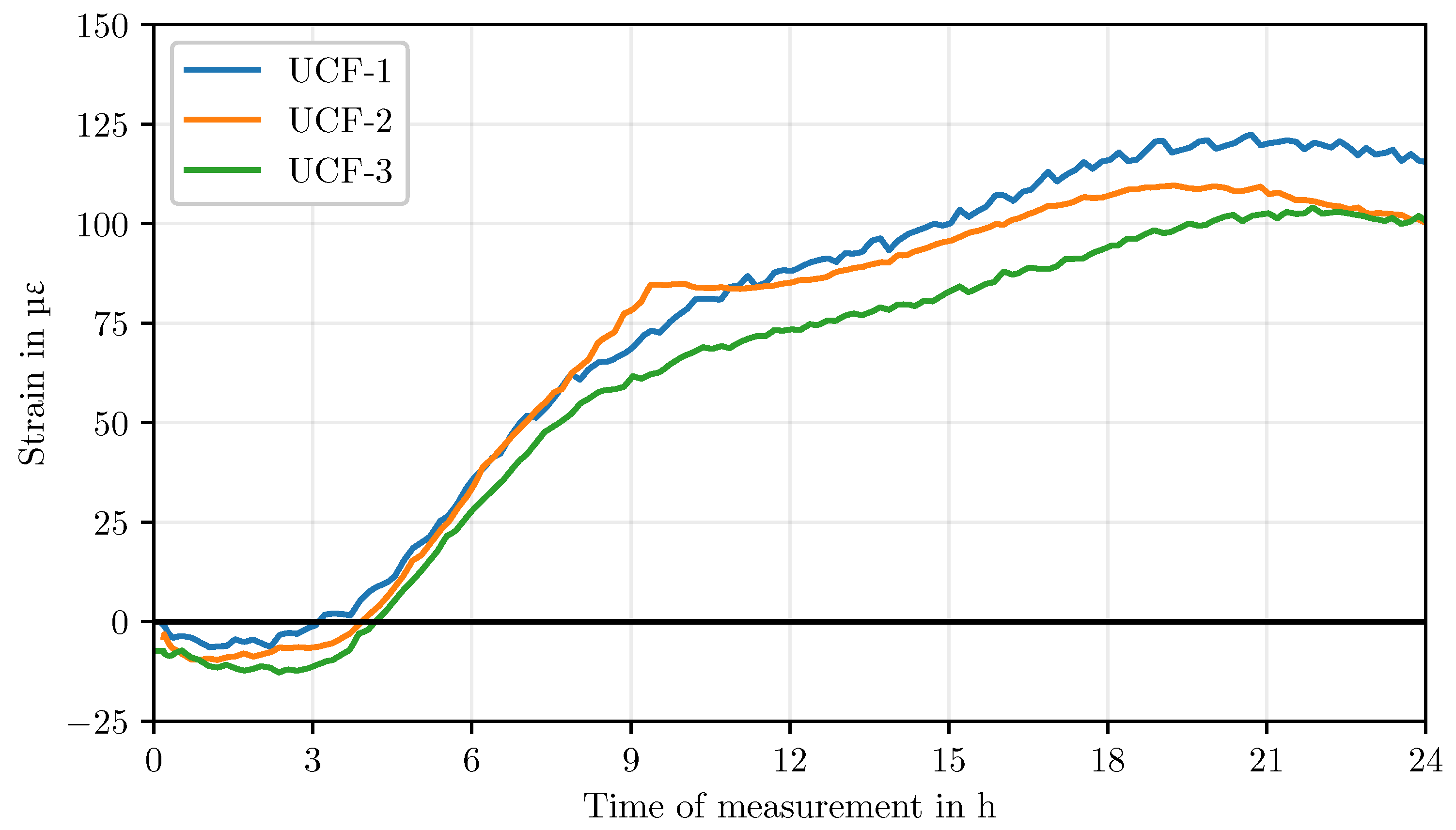
The explanations presented in the introduction illustrate the complexity of measuring early deformation in cementitious matrices. In addition to the intrinsic challenges of deformation measurement, there are influences on the measurement process itself, an aspect that affects almost all measurement methods. In order to investigate these influences and to evaluate the reproducibility of the measurements, all tests were carried out on replicates, taking into account variations in time, sensor and material. Figure 9 shows the temperature compensated evolution of the UCF measurements (coefficient: 9.8 ). According to [62], moisture compensation was not necessary as the UCF showed no significant effect in this respect. Measurements were started 9 after contact between water and cement as described in Section 2.1. In general, the curve appears to be reproducible with only a small range ( = 4.9 , = 24.5 ), especially considering that these are replicates and not repeated measurements. The small range of the three samples within the first 9 is noticeable. The evolution initially shows a negative deformation until about 4 after mixing. Then a transition to positive deformation can be observed, which continues until a turning point at about 21 . Another observation is the change in curvature that occurs in all three curves after about 9 .
Figure 9.
Deformation comparison of UCF, temperature compensated.
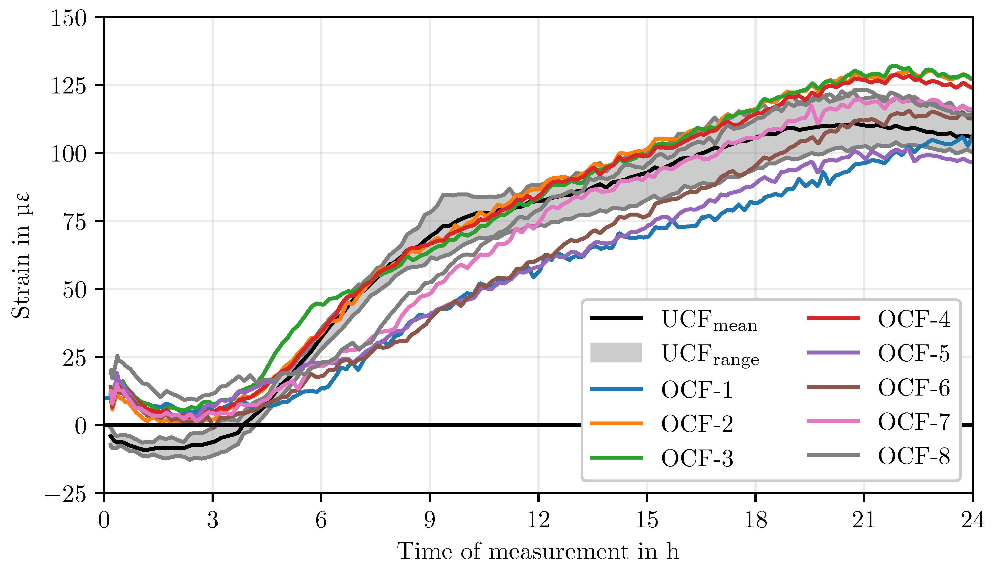
Although decoated fibers are advantageous for these measurements, practical applications, especially with larger samples or coarser aggregates, require more robust FOS. While handling decoated fibers is possible in controlled laboratory environments and with small samples, it is challenging in larger applications due to fiber damage. To address this issue, eight additional replicates were tested with the ORMOCER®coating (OCF). As described in Section 2.1, the measurement began 9 after the water and cement came into contact. Figure 10 shows the comparison of the OCF and UCF curves. The data have been processed and temperature compensated (coefficient: 10.5 ) according to the method described in Section 2.1. Note that the OCF values are only temperature compensated at this point; moisture compensation is still pending. The temperature compensation had a relatively small effect on the deformation values. This is due to the moderate development of hydration heat of 1.4 caused by the small sample size, resulting in maximum strain changes of 15 . The results also show that the OCF still has a significant deviation from the UCF, indicating that moisture compensation still needs to be performed.
Figure 10.
Comparison of UCF and OCF deformation evolution, temperature compensated.
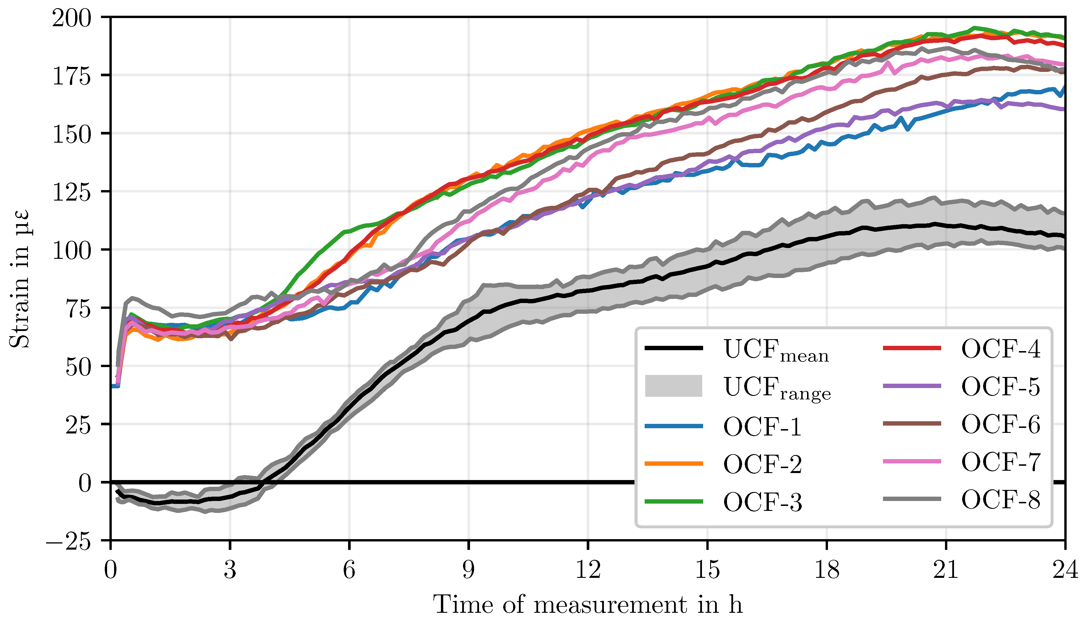
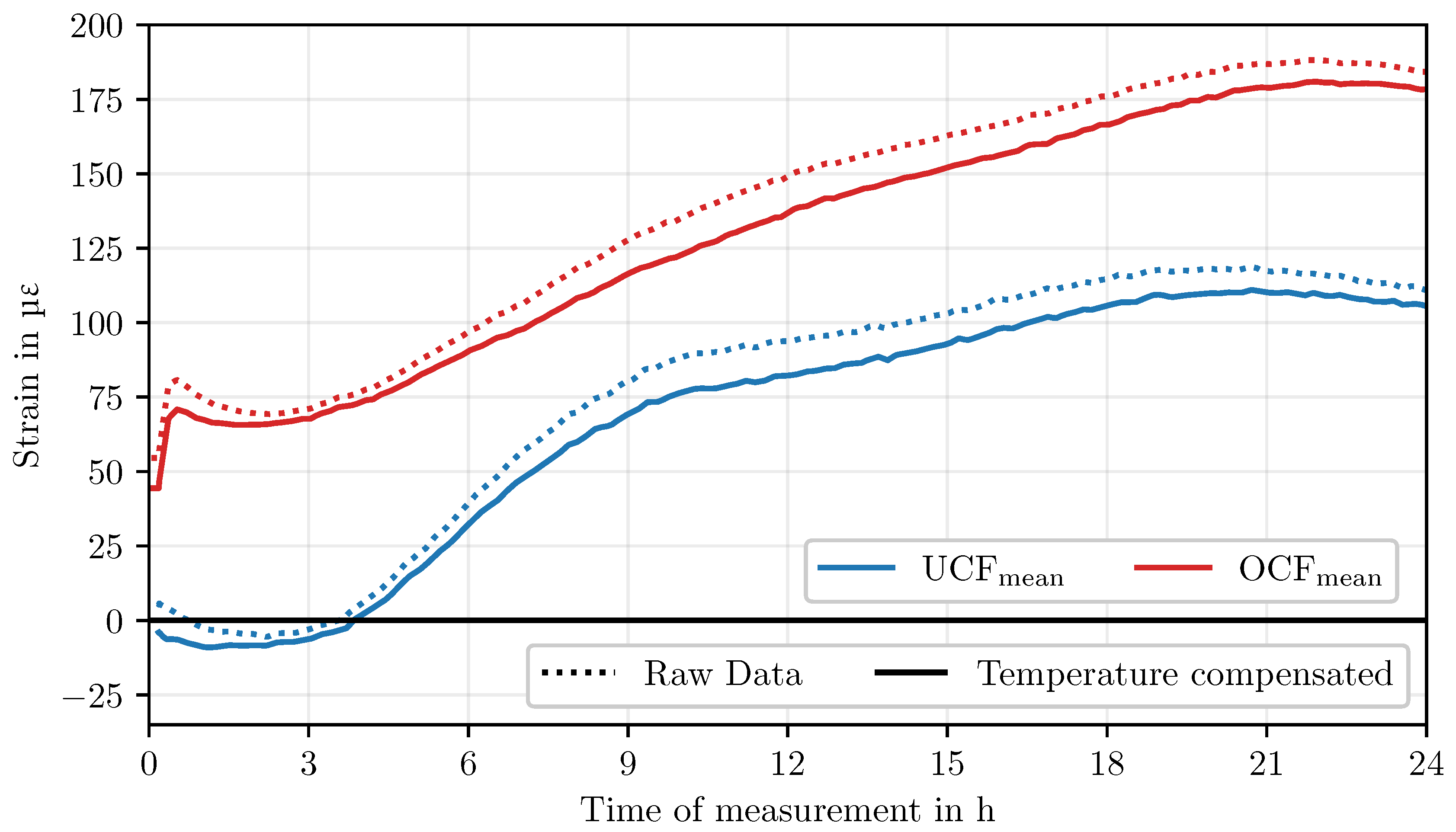
Taking into account the influence of humidity on the OCF leads to significantly larger compensation effects than temperature compensation alone, as can be seen in Figure 11. After applying moisture compensation, the measured values of the OCF samples converge to those of the UCF samples. Despite the convergence, deviations between OCF and UCF can still be observed, especially during the first 4 after the start of the measurement. After this period, however, the curves increasingly approximate each other. In the further course of the measurement, OCF-1, OCF-5 and OCF-6 show a deviation of about 25 from the mean value of the UCF samples after about 7 . In addition, these samples do not show the characteristic strain change observed in the UCF samples after about 9 . OCF-2, OCF-3 and OCF-4 show an evolution largely comparable to that of the UCF samples. OCF-7 and OCF-8 show a time lag with respect to the UCF samples. Furthermore, all samples show a turning point after about 22 , with OCF-1 showing a slight time shift.
Figure 11.
Comparison of UCF and OCF deformation evolution, fully compensated.
To estimate the dispersion of all covered samples, Table 5 lists the ranges and means at different times. Comparing all samples, a range of 30.1 can be seen after 24 .
As described in Section 2.1, an uncovered reference specimen was also tested. Figure 12 shows the strain curve of this sample compared to the mean of the OCF test series. The strain curve is nearly identical up to a measurement time of approximately 5 . From this point on, a change in the strain curve can be seen. Up to a measurement time of about 15 , lower strains can be observed with a simultaneous greater acceleration of the measured values. The peak of the positive strains occurs about 3 earlier than for the covered samples. However, a continuous positive strain is observed.
Figure 13 shows the spatial and temporal evolution of the deformations along the entire fiber length of samples UCF-1 and OCF-2 at 6 h 12 h 18 after the start of the measurement. The data from UCF-1 were temperature compensated, while both temperature and moisture compensation were performed for OCF-2. The Region of Total Strain Transfer (ROTST) is shown and represents the area where, according to the strain transfer models, complete strain transfer should occur, minus the bedding length and the length of the 24G needles. Within the ROTST is the ROA, which represents the area in which the deformation measurements are used for quantitative evaluation. The comparison between UCF-1 and OCF-2 shows a high degree of correlation between the strain curves. Slight differences can be seen especially in the peripheral zones. The time evolution of the strain profiles from 6 to 12 to 18 shows a continuous increase in expansion, with the basic shape of the profile remaining the same.
4. Discussion
The analysis of the measured values indicates a high degree of overall agreement between the different samples, especially considering that these are replicates and not repeated measurements. This consistency underscores the reliability and reproducibility of the fiber optic measurement technique employed, as well as the efficacy of FOS for the detection of early deformations in cement-based matrices. The small range of the measured values between the different samples is an aspect that should be emphasized.
The longitudinal sections of the strain measurement confirm the assumptions regarding the strain transfer from previous studies on deformation measurement within the matrix using FOS [22]. A stable strain signal is observed over the entire ROA, confirming a uniform strain transfer of the matrix deformations to the sensor. The stability of the strain signal after the short embedding shows that for this matrix the chosen sensor integration provides sufficient coupling between fiber and matrix.
The influence of temperature on the measurement results can be well compensated in the tests performed. This is mainly due to the fact that the hydration heat development is comparatively low within the used mortar matrix and the selected specimen geometry. For systems with higher hydration temperatures, deviations may occur that are not fully captured by the current method. This potential limitation is caused by the fact that the temperature evolution in the present experiments was only measured at certain points. Therefore, possible temperature inhomogeneities within the sample cannot be excluded. For future investigations, especially for systems with higher heat development, a more detailed spatial and temporal recording of the temperature distribution is recommended in order to achieve a more precise compensation.
The influence of moisture on the fiber coating and thus on the measurement results is a further key point of discussion. The performed moisture compensation shows an approximation of the measured values of the OCF to the reference values of the UCF. This observation emphasizes the importance of moisture compensation for accurate measurements with polymer coated FOS in cementitious matrices. Despite the significant improvement due to moisture compensation, there is still potential for further improvement. This is particularly evident in the first 2 h to 3 after mixing. The remaining deviations at this early phase could be due to several factors: First, the compensation values used are based on measurements in a cement solution. The more complex structure and composition of the mortar matrix could lead to different moisture interactions with the fiber coating that are not fully captured by the cement solution calibration. Secondly, inhomogeneities in the moisture distribution both spatially within the sample and temporally during the hydration process must be taken into account. The early phase of cement hydration is characterized by rapid and complex changes in microstructure and moisture distribution. These dynamic processes can lead to local moisture variations that may not be fully captured by a single compensation function.
Analysis of the deformation curves in the different phases of hydration provides insight into the complex processes that take place in cementitious matrices. The negative deformations observed up to about two hours after mixing indicate settlement processes. This phase correlates in time with the induction and dormant periods of cement hydration as described by [35]. During this period, mainly dissolution and rearrangement processes take place, leading to a slight reduction in volume and marking the area of time zero [55]. The subsequent increase in positive deformations up to about nine hours after mixing can potentially be attributed to ettringite formation, thermal expansion or reabsorption of bleeding water [39,41,72]. This phase also falls within the acceleration period of cement hydration, where the formation of early hydration products leads to volume expansion [31,34,37]. After 9 h to 11 a decrease in the expansion rate is observed. This may indicate a superposition of several effects in the matrix under investigation. First, ettringite formation could be reduced and expansive hydration continues; second, the onset of self-desiccation and structure formation could lead to a slowdown in expansion. This observation is in accordance with the theories of Bažant, who proposes that hydration is essentially an expansive process [37].
It is noteworthy that the reduction of the increase after 9 is not observed for samples OCF-1, OCF-5 and OCF-6. This deviation from the reference, which is about 25 , could be due to several factors. Possible causes are temperature variations during air conditioning or local inhomogeneities in the sample structure. For samples OCF-7 and OCF-8, the increase in deformation is slightly shifted in time. Temperature variations could also be involved, although other factors such as minor differences in the mixture composition or local variations in hydration kinetics cannot be excluded. Figure 14 shows the ambient temperature curves during the tests of specimens OCF-1 and OCF-2. For comparison, the average temperature curve for all OCF series specimens is shown. Temperatures were recorded using electrical temperature sensors (TMP117 [73], SHT45 [74]) in close proximity to the mold. It is possible to identify the differences in the temperature curve between the two series. When comparing the deviations from the mean temperature curve, a convergence may be observed between the deviations in the strain profiles (Figure 11) and the ambient temperatures. However, the differences from the mean temperature curve are only about ±0.1K. It is unlikely that the observed temperature effect is directly attributable to the measurement system, since the temperature coefficient of the fiber used is comparatively low. Rather, it is plausible that the higher temperatures influence the reaction kinetics and lead to accelerated structure formation in the cement matrix and to thermal expansion [42,43,72].
Compared to the literature, the measurements show an expansion, which is in contrast to many studies that report purely negative deformations (Section 1). This discrepancy could be caused by different measurement methods, material compositions or environmental conditions [75]. A direct comparison of the different methods is difficult due to significant differences in the measurement procedures. Factors such as environmental conditions, mixing energy input, compaction energy input and other manufacturing parameters can have a significant effect on the measurement results within the first 24 [75]. In addition, the results of the uncovered sample do not show direct agreement with the results of [40]. Due to its storage in an area with direct air circulation, reabsorption of bleeding water does not seem to be the sole cause of the expansion. It can be assumed that this effect also depends on the other three additional factors described above (ettringite formation, thermal expansion, hydration).
Despite these variations, the scatter of the measured values is comparable or even lower than that of established methods such as the Corrugated Tube Method or the Plastic Sleeve Test Method [49,60]. In addition, DFOS measurements show significantly less scatter than optical measurement methods [48]. An important aspect to consider when studying early deformation is the preparation conditions of the samples. The results of this study suggest that factors such as mixing energy, compaction, initial moisture and temperature conditions can have a significant influence on the deformation behavior in the first hours after mixing. This observation is supported by [39,42,43], where the influence of sample preparation on autogenous deformation was investigated and it was found that even small variations in preparation method can lead to measurable differences in deformation behavior.
5. Conclusion
Investigations of early deformation in cementitious systems have shown that the results depend primarily on the intrinsic properties of the material, but can also be significantly influenced by the chosen measurement method. These results indicate that, despite decades of research in the field, not all influences on the various measurement techniques are sufficiently understood. In particular, observing how even small changes in environmental conditions can lead to a noticeable scattering of the measured values illustrates the complexity of the early deformation processes in mortars.
A key approach to improve the accuracy and validity of results is the systematic investigation and quantification of the specific influences on a particular measurement method. This procedure can reduce the dispersion of the measured values and increase the reliability of the data. The investigations carried out in this study using DFOS have demonstrated the high sensitivity of this measurement technique to small changes in material structure. However, the observations also demonstrate the complexity of early deformation processes in cementitious matrices. Even minor variations in temperature, humidity, or manufacturing conditions can have significant effects on the deformation behavior. Such findings emphasize the need for a holistic investigation of early deformation, taking into account both the material processes and the measurement aspects.
DFOS has proven to be a promising tool for accurate and reliable measurements. It enables the determination of early deformations with high accuracy and low dispersion and offers the potential to gain new insights into the structural development of cementitious matrices. The spatial resolution of the DFOS also opens up the possibility of studying specific phenomena such as plastic shrinkage cracking, deformations at formwork transitions, or the influence of reinforcements and other fixtures. In this respect, a major advantage of DFOS technology could be the ability to continuously monitor concrete components over their entire life cycle, from production through curing to loading. This opens up new possibilities for optimizing the use of concrete structures.
The deformations obtained using the DFOS technique are consistent with the theories in the differential literature (hydration, thermal expansion, reabsorption of bleeding water, ettringite formation) which predict positive deformations in the early phase of cement hydration. A key issue in recent research in this area is the extent to which the influence of these four expansion components is significant. It has been shown that moisture and temperature compensation is essential for accurate measurements. After compensation, measurements on OCF and UCF give comparable results, demonstrating the reliability of the method. However, measurements on uncovered specimens also show that reabsorption of bleed water is most likely not the only reason for the positive deformations.
Author Contributions
MW and DM performed the experiments with the DFOS and analysed the data. MW investigated the data in the context of the topic and wrote the final paper. KH accompanied the experiments and advised on the conceptual design of the paper. All authors have read and approved the final paper.
Data Availability Statement
The datasets used and analyzed in the current study are available from the corresponding author on reasonable request.
Acknowledgments
This research is funded by the Deutsche Forschungsgemeinschaft (DFG, German Research Foundation)—518861712 and 498129749.
Conflicts of Interest
The author declare that they have no conflict of interest.
References
- Samiec, D. Distributed fibre-optic temperature and strain measurement with extremely high spatial resolution. Photonik International 2012, 1, 10–13.
- Weisbrich, M.; Holschemacher, K.; Bier, T. Validierung verteilter faseroptischer Sensorik zur Dehnungsmessung im Betonbau. Beton- und Stahlbetonbau 2021, 116, 648–659. [CrossRef]
- Bado, M.F.; Casas, J.R. A Review of Recent Distributed Optical Fiber Sensors Applications for Civil Engineering Structural Health Monitoring. Sensors 2021, 21, 1818. [CrossRef]
- Barrias, A.; Rodriguez, G.; Casas, J.R.; Villalba, S. Application of distributed optical fiber sensors for the health monitoring of two real structures in Barcelona. Structure and Infrastructure Engineering 2018, 14, 967–985. [CrossRef]
- Moser, F.; Lienhart, W.; Woschitz, H.; Schuller, H. Long-term monitoring of reinforced earth structures using distributed fiber optic sensing. Journal of Civil Structural Health Monitoring 2016, 6, 321–327. [CrossRef]
- Inaudi, D.; Glisic, B. Application of distributed fiber optic sensory for SHM. In Proceedings of the Proceedings of the 2nd International Conference on Structural Health Monitoring of Intelligent Infrastructure, SHMII 2005, 2006, pp. 163–169.
- Becks, H.; Baktheer, A.; Marx, S.; Classen, M.; Hegger, J.; Chudoba, R. Monitoring concept for the propagation of compressive fatigue in externally prestressed concrete beams using digital image correlation and fiber optic sensors. Fatigue & Fracture of Engineering Materials & Structures 2023, 46, 514–526. [CrossRef]
- Berrocal, C.G.; Fernandez, I.; Rempling, R. Crack monitoring in reinforced concrete beams by distributed optical fiber sensors. Structure and Infrastructure Engineering 2021, 17, 124–139. [CrossRef]
- Chapeleau, X.; Bassil, A. A general solution to determine strain profile in the core of distributed fiber optic sensors under any arbitrary strain fields. Sensors 2021, 21, 5423. [CrossRef]
- Fischer, O.; Thoma, S.; Crepaz, S. Quasikontinuierliche faseroptische Dehnungsmessung zur Rissdetektion in Betonkonstruktionen. Beton- und Stahlbetonbau 2019, 114, 150–159. [CrossRef]
- Henault, J.M.; Quiertant, M.; Delepine-Lesoille, S.; Salin, J.; Moreau, G.; Taillade, F.; Benzarti, K. Quantitative strain measurement and crack detection in RC structures using a truly distributed fiber optic sensing system. Construction and Building Materials 2012, 37, 916–923. [CrossRef]
- Herbers, M.; Richter, B.; Gebauer, D.; Classen, M.; Marx, S. Crack monitoring on concrete structures: Comparison of various distributed fiber optic sensors with digital image correlation method. Structural Concrete 2023, pp. 6123–6140. [CrossRef]
- Kishida, K.; Imai, M.; Kawabata, J.; Guzik, A. Distributed Optical Fiber Sensors for Monitoring of Civil Engineering Structures. Sensors 2022, 22, 4368. [CrossRef]
- Lienhart, W.; Buchmayer, F.; Klug, F.; Monsberger, C.M. Distributed Fiber Optic Sensing on a Large Tunnel Construction Site: Increased Safety, More Efficient Construction and Basis for Condition-Based Maintenance. In Proceedings of the International Conference on Smart Infrastructure and Construction 2019 (ICSIC), Cambridge, UK, 2019; pp. 595–604. [CrossRef]
- Lopez-Higuera, J.M.; Cobo, L.R.; Incera, A.Q.; Cobo, A. Fiber Optic Sensors in Structural Health Monitoring. Journal of Lightwave Technology 2011, 29, 587–608. [CrossRef]
- Minardo, A.; Persichetti, G.; Testa, G.; Zeni, L.; Bernini, R. Long term structural health monitoring by Brillouin fibre-optic sensing: a real case. Journal of Geophysics and Engineering 2012, 9, S64–S69. [CrossRef]
- Monsberger, C.M.; Lienhart, W. Distributed Fiber Optic Shape Sensing of Concrete Structures. Sensors 2021, 21, 6098. [CrossRef]
- Monsberger, C.M.; Lienhart, W. Distributed fiber optic shape sensing along shotcrete tunnel linings: Methodology, field applications, and monitoring results. Journal of Civil Structural Health Monitoring 2021, 11, 337–350. [CrossRef]
- Zdanowicz, K.; Gebauer, D.; Koschemann, M.; Speck, K.; Steinbock, O.; Beckmann, B.; Marx, S. Distributed fiber optic sensors for measuring strains of concrete, steel, and textile reinforcement: Possible fields of application. Structural Concrete 2022, 23, 3367–3382. [CrossRef]
- Wijaya, H.; Rajeev, P.; Gad, E. Distributed optical fibre sensor for infrastructure monitoring: Field applications. Optical Fiber Technology 2021, 64, 102577. [CrossRef]
- Leung, C.K.Y.; Wan, K.T.; Inaudi, D.; Bao, X.; Habel, W.; Zhou, Z.; Ou, J.; Ghandehari, M.; Wu, H.C.; Imai, M. Review: optical fiber sensors for civil engineering applications. Materials and Structures 2013, 48, 871–906. [CrossRef]
- Weisbrich, M.; Holschemacher, K.; Bier, T. Comparison of different fiber coatings for distributed strain measurement in cementitious matrices. Journal of Sensors and Sensor Systems 2020, 9, 189–197. [CrossRef]
- Weisbrich, M. Verbesserte Dehnungsmessung im Betonbau durch verteilte faseroptische Sensorik. Phd thesis, Technische Universität Bergakademie Freiberg, 2020.
- Weisbrich, M.; Holschemacher, K. Comparison between different fiber coatings and adhesives on steel surfaces for distributed optical strain measurements based on Rayleigh backscattering. Journal of Sensors and Sensor Systems 2018, 7, 601–608. [CrossRef]
- Zhang, H.; Hao, L.; Zhang, S.; Xiao, J.; Poon, C.S. Advanced measurement techniques for plastic shrinkage and cracking in 3D-printed concrete utilising distributed optical fiber sensor. Additive Manufacturing 2023, 74, 103722. [CrossRef]
- Kayondo, M.; Combrinck, R.; Boshoff, W. State-of-the-art review on plastic cracking of concrete. Construction and Building Materials 2019, 225, 886–899. [CrossRef]
- Holt, E.E.; Janssen, D.J. Influence of Early Age Volume Changes on Long-Term Concrete Shrinkage. Transportation Research Record: Journal of the Transportation Research Board 1998, 1610, 28–32. [CrossRef]
- Ghourchian, S.; Wyrzykowski, M.; Lura, P. A practical approach for reducing the risk of plastic shrinkage cracking of concrete. RILEM Technical Letters 2017, 2, 40–44. [CrossRef]
- Li, L.; Dao, V.; Lura, P. Autogenous deformation and coefficient of thermal expansion of early-age concrete: Initial outcomes of a study using a newly-developed Temperature Stress Testing Machine. Cement and Concrete Composites 2021, 119, 103997. [CrossRef]
- Gowripalan, N., Autogenous Shrinkage of Concrete at Early Ages. In ACMSM25; Springer Singapore, 2019; pp. 269–276. [CrossRef]
- John, E.; Lothenbach, B. Cement hydration mechanisms through time – a review. Journal of Materials Science 2023, 58, 9805–9833. [CrossRef]
- Michaëlis, W. The Hardening Process of Hydraulic Cements. Cement and Engineering News 1907, pp. 1–29.
- Chetalier, H.L. Experimental Researches on the Constitution of Hydraulic Mortars; McGraw-Hill Publishing Co.: New York, 1905.
- Powers, T.C. Some aspects of the hydration of Portland cement. Technical Report 125, J. Port. Cem. Assoc. Res. Dev. Lab., 1961.
- Scrivener, K.; Ouzia, A.; Juilland, P.; Kunhi Mohamed, A. Advances in understanding cement hydration mechanisms. Cement and Concrete Research 2019, 124, 105823. [CrossRef]
- Moses, P.; Perumal, S.B. Hydration of Cement and its Mechanisms. IOSR Journal of Mechanical and Civil Engineering 2016, 16, 17–31. [CrossRef]
- Rahimi-Aghdam, S.; Masoero, E.; Rasoolinejad, M.; Bažant, Z.P. Century-long expansion of hydrating cement counteracting concrete shrinkage due to humidity drop from selfdesiccation or external drying. Materials and Structures 2019, 52. [CrossRef]
- Diamond, S. Delayed ettringite formation - Processes and problems. Cement and Concrete Composite 1996, 18, 205–215. [CrossRef]
- Bjøntegaard, Ø. and Hammer, T.A and Sellevold, E.J.. On the measurement of free deformation of early age cement paste and concrete. Cement and Concrete Composites 2004, 26, 427–435. [CrossRef]
- Mohr, B.; Hood, K. Influence of bleed water reabsorption on cement paste autogenous deformation. Cement and Concrete Research 2010, 40, 220–225. [CrossRef]
- Wyrzykowski, M.; Hu, Z.; Ghourchian, S.; Scrivener, K.; Lura, P. Corrugated tube protocol for autogenous shrinkage measurements: review and statistical assessment. Materials and Structures 2016, 50. [CrossRef]
- Vosoughi, P.; Taylor, P.; Najimi, M.; Horton, R. Effect of Exposure Conditions and Internal Curing on Pore Water Potential Development in Cement-Based Materials. Transportation Research Record: Journal of the Transportation Research Board 2020, 2675, 184–191. [CrossRef]
- Jensen, O.M.; Hansen, P.F. Autogenous deformation and RH-change in perspective. Cement and Concrete Research 2001, 31, 1859–1865. [CrossRef]
- Hammer, T.; Bjøntegaard, Ø.; Sellevold, E. Measurement methods for testing of early age autogenous strain. In Proceedings of the International RILEM Conference on Early Age Cracking in Cementitious Systems. RILEM Publications SARL, 2003, pp. 217–228.
- Kurup, D.S.; Mohan, M.K.; Van Tittelboom, K.; De Schutter, G.; Santhanam, M.; Rahul, A. Early-age shrinkage assessment of cementitious materials: A critical review. Cement and Concrete Composites 2024, 145, 105343. [CrossRef]
- Al-Amoudi, O.; Maslehuddin, M.; Shameem, M.; Ibrahim, M. Shrinkage of plain and silica fume cement concrete under hot weather. Cement and Concrete Composites 2007, 29, 690–699. [CrossRef]
- Hong, M.; Lei, D.; Zhu, F.; Bai, P.; He, J. Experimental research on aggregate restrained shrinkage and cracking of early-age cement paste. Cement and Concrete Research 2023, 172, 107246. [CrossRef]
- Ghourchian, S.; Wyrzykowski, M.; Baquerizo, L.; Lura, P. Susceptibility of Portland cement and blended cement concretes to plastic shrinkage cracking. Cement and Concrete Composites 2018, 85, 44–55. [CrossRef]
- Zieliński, A.; Schindler, A.K. Plastic-sleeve test method to measure autogenous and drying shrinkage in paste, mortar, and concrete: Test Results. Measurement 2024, 237, 115138. [CrossRef]
- Slowik, V.; Schlattner, E.; Klink, T. Experimental investigation into early age shrinkage of cement paste by using fibre Bragg gratings. Cement & Concrete Composites 2004, 26, 473–479. [CrossRef]
- Wong, A.C.; Childs, P.A.; Berndt, R.; Macken, T.; Peng, G.D.; Gowripalan, N. Simultaneous measurement of shrinkage and temperature of reactive powder concrete at early-age using fibre Bragg grating sensors. Cement and Concrete Composites 2007, 29, 490–497. [CrossRef]
- Silva, K.S.; Silva, F.; Mahfoud, T.; Khelidj, A.; Brientin, A.; Azevedo, A.; Delgado, J.; de Lima, A.B. On the Use of Embedded Fiber Optic Sensors for Measuring Early-Age Strains in Concrete. Sensors 2021, 21, 4171. [CrossRef]
- Francinete, P.; da Silva, E.F.; de Mendonça Lopes, A.N., Comparative Study Between Strain Gages for Determination of Autogenous Shrinkage. In 3rd International Conference on the Application of Superabsorbent Polymers (SAP) and Other New Admixtures Towards Smart Concrete; Springer International Publishing, 2019; pp. 114–122. [CrossRef]
- Gong, J.; Mao, Z.; Cao, Z.; Huang, X.; Deng, M. Effect of Different Fineness of Cement on the Autogenous Shrinkage of Mass Concrete under Variable Temperature Conditions. Materials 2023, 16, 2367. [CrossRef]
- Weicken, H. Experimentelle Methodik zur Bestimmung des autogenen Schwindverhaltens von Hochleistungsbetonen. Phd thesis, Institut für Baustoffe, Universität Hannover, 2019.
- Eppers, S.; Müller, C. The shrinkage cone method for measuring the autogenous shrinkage - an alternative to the corrugated tube method. In Proceedings of the International RILEM Conference on Use of Superabsorbent Polymers and Other New Additives in Concrete. RILEM Publications SARL, 2010, pp. 67–76.
- Kucharczyková, B.; Kocáb, D.; Rozsypalová, I.; Karel, O.; Misák, P.; Vymazal, T. Measurement and evaluation proposal of early age shrinkage of cement composites using shrinkage-cone. IOP Conference Series: Materials Science and Engineering 2018, 379, 012038. [CrossRef]
- Sant, G.; Lura, P.; Weiss, J. Measurement of Volume Change in Cementitious Materials at Early Ages: Review of Testing Protocols and Interpretation of Results. Transportation Research Record: Journal of the Transportation Research Board 2006, 1979, 21–29. [CrossRef]
- Lura, P.; Jensen, O.M. Measuring techniques for autogenous strain of cement paste. Materials and Structures 2006, 40, 431–440. [CrossRef]
- Mejlhede Jensen, O.; Freiesleben Hansen, P. A dilatometer for measuring autogenous deformation in hardening portland cement paste. Materials and Structures 1995, 28, 406–409. [CrossRef]
- Bjøntegaard, Ø and Hammer, T.A.. RILEM TC 195-DTD: MOTIVE AND TECHNICAL CONTENT. In Proceedings of the International RILEM Conference on Volume Changes of Hardening Concrete: Testing and Mitigation. Technical University of Denmark, Lyngby, Denmark, 2006.
- Weisbrich, M.; Messerer, D.; Holzer, F.; Trommler, U.; Roland, U.; Holschemacher, K. The Impact of Liquids and Saturated Salt Solutions on Polymer-Coated Fiber Optic Sensors for Distributed Strain and Temperature Measurement. Sensors 2024, 24, 4659. [CrossRef]
- Leung, C.K.Y. Interfacial changes of optical fibers in the cementitious environment. Journal of Materials Science 2000, 35, 6197–6208. [CrossRef]
- Li, Q.; Li, G.; Wang, G. Effect of the plastic coating on strain measurement of concrete by fiber optic sensor. Measurement 2003, 34, 215–227. [CrossRef]
- Yuan, L.; Zhou, L. Sensitivity coefficient evaluation of an embedded fiber-optic strain sensor. Sensors and Actuators A: Physical 1998, 69, 5–11. [CrossRef]
- Li, D.S.; Sr., H.L.; Ren, L.; Song, G. Strain transferring analysis of fiber Bragg grating sensors. Optical Engineering 2006, 45, 1–8. [CrossRef]
- Li, H.N.; Zhou, G.D.; Ren, L.; Li, D.S. Strain transfer coefficient analyses for embedded fiber bragg grating sensors in different host materials. Journal of Engineering Mechanics 2009, 135, 1343–1353. [CrossRef]
- Luna Innovations Incorporated. OPTICAL DISTRIBUTED SENSOR INTERROGATOR (Model ODiSI B), 2013.
- Innovative Sensor Technology IST AG. TSic 506F TO92 Temperature Sensor IC.
- SCHWENK Zement KG. CEM I 42,5 R Portland Cement, 2012.
- FBGS International N.V.. DTG coating Ormocer®-T for temperature sensing applications, 2015.
- Wyrzykowski, M.; Lura, P. Moisture dependence of thermal expansion in cement-based materials at early ages. Cement and Concrete Research 2013, 53, 25–35. [CrossRef]
- Texas Instruments Incorporated. TMP117 High-Accuracy, Low-Power, Digital Temperature Sensor, 2022.
- Sensirion AG. Datasheet – SHT4x - 4th Gen. Relative Humidity and Temperature Sensor, 2024.
- Bjøntegaard, Ø and Hammer, TA. RILEM TC 195-DTD: MOTIVE AND TECHNICAL CONTENT. In Proceedings of the International RILEM Conference on Volume Changes of Hardening Concrete: Testing and Mitigation. Technical University of Denmark, Lyngby, Denmark, 2006.
Figure 1.
Proposal for the classification of measurement methods intended for the detection of deformations of cementitious matrices.
Figure 1.
Proposal for the classification of measurement methods intended for the detection of deformations of cementitious matrices.
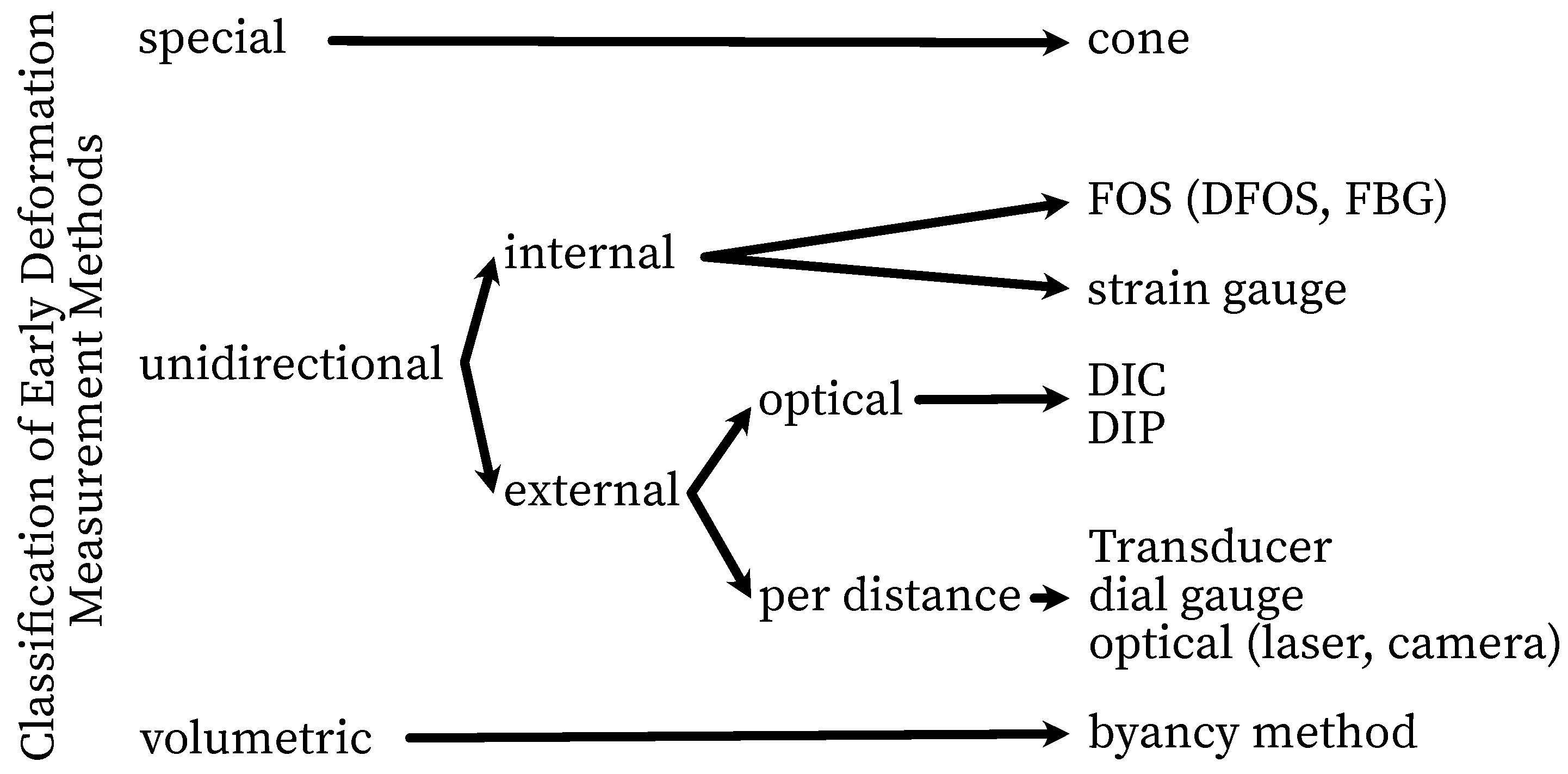
Figure 2.
Strain transfer according to [2,23,64,65,66,67] (a), ITZ implementation considerations (b)
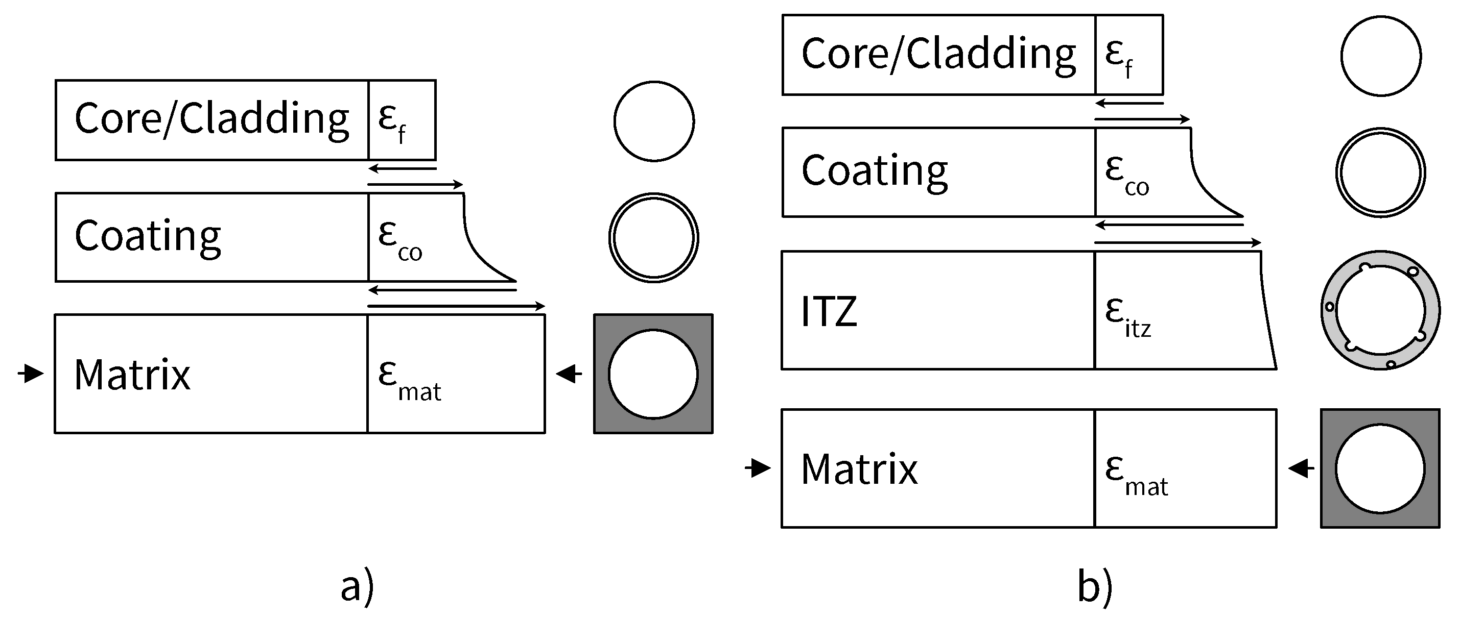
Figure 3.
Experimental setup.
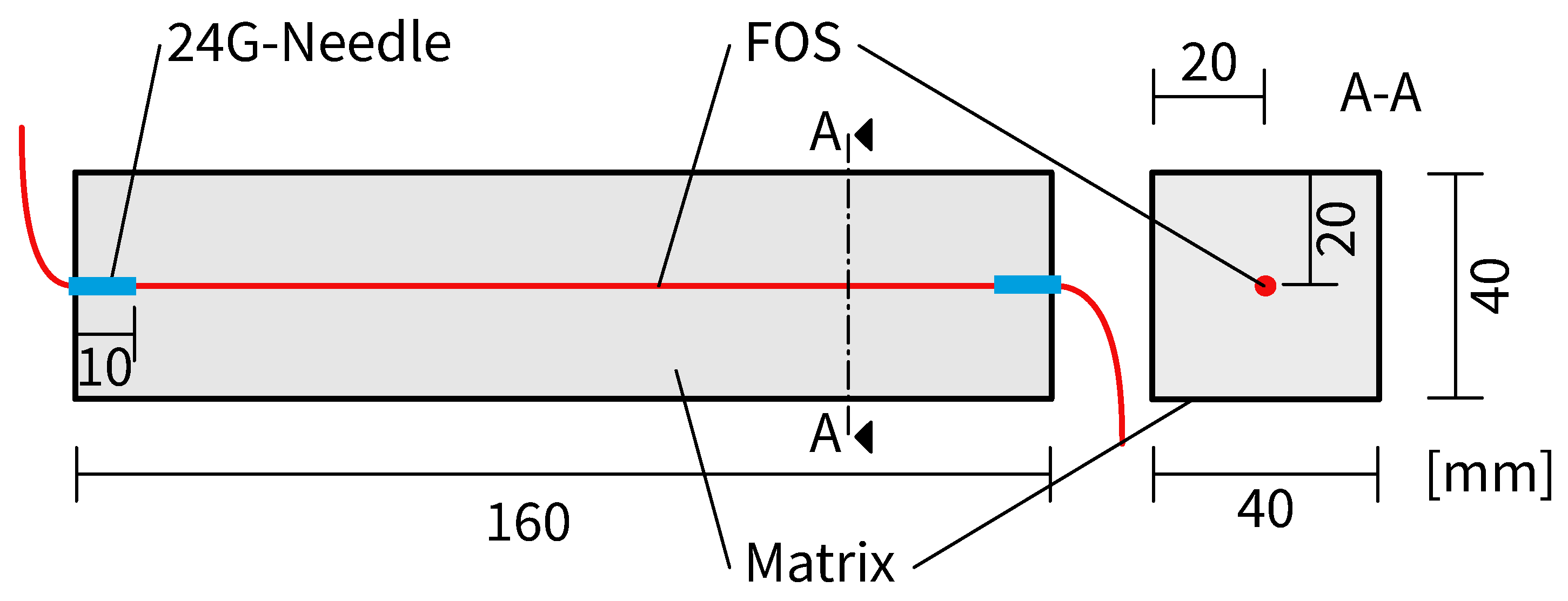
Figure 4.
FOS placed in the mold before casting.
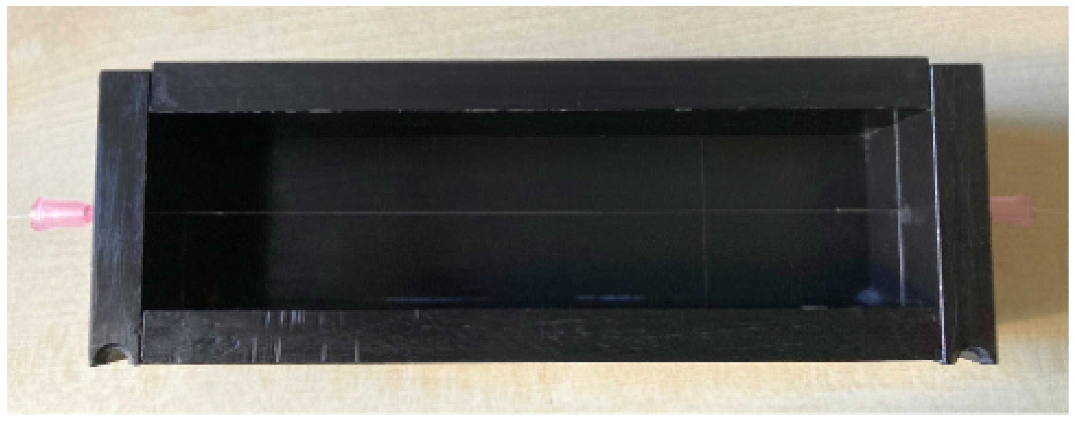
Figure 6.
Data processing.
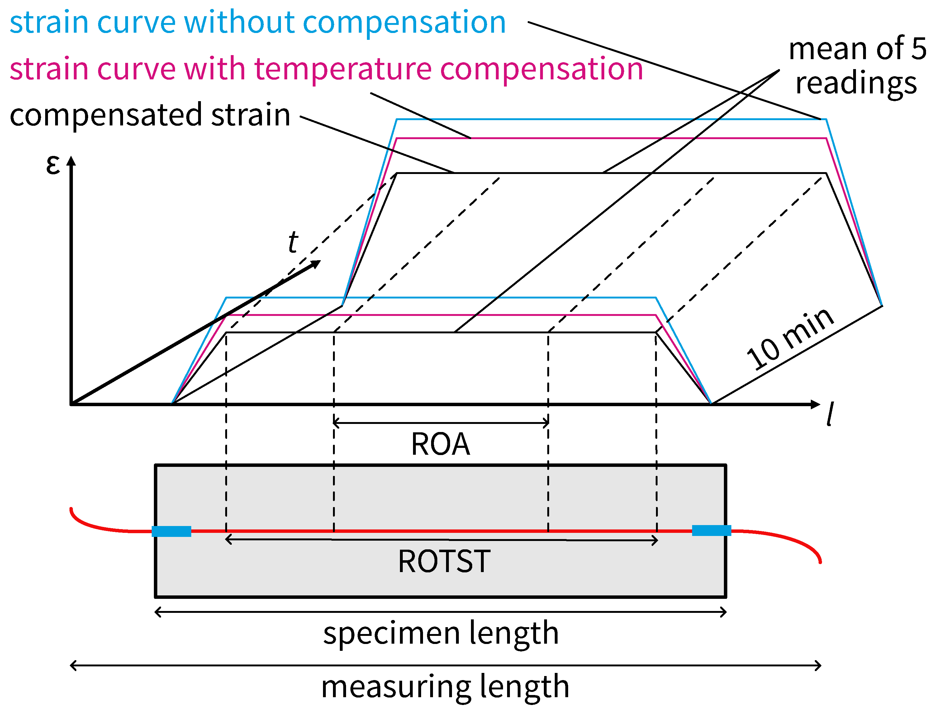
Figure 12.
Deformation comparison for the uncovered specimen.
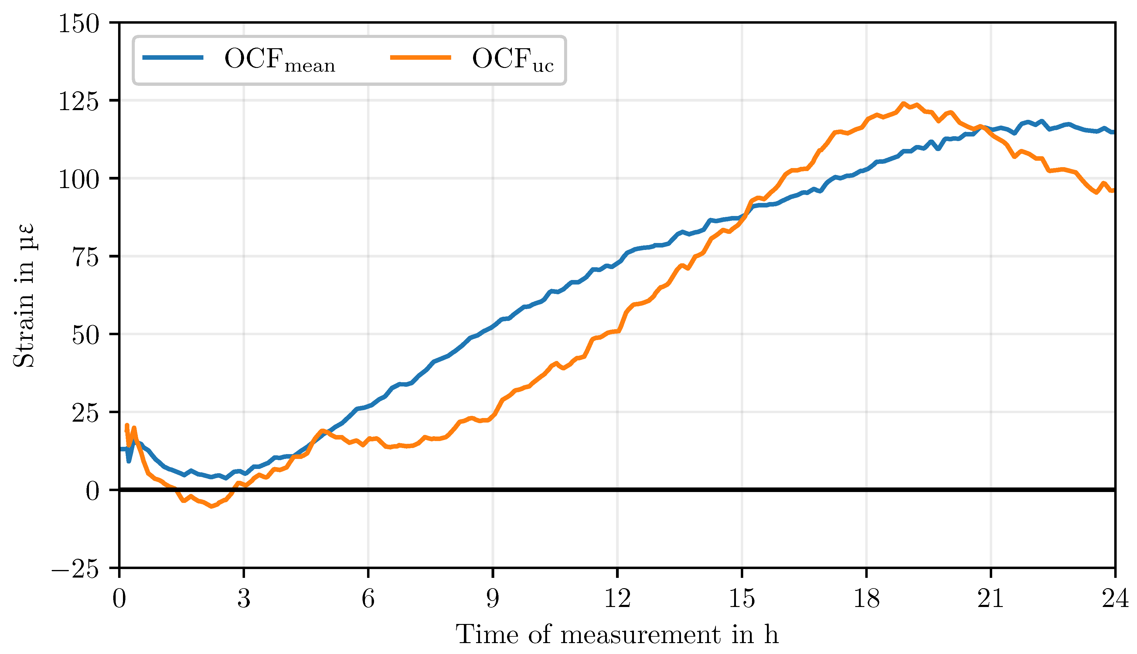
Figure 13.
Longitudinal section of a UCF and an OCF.
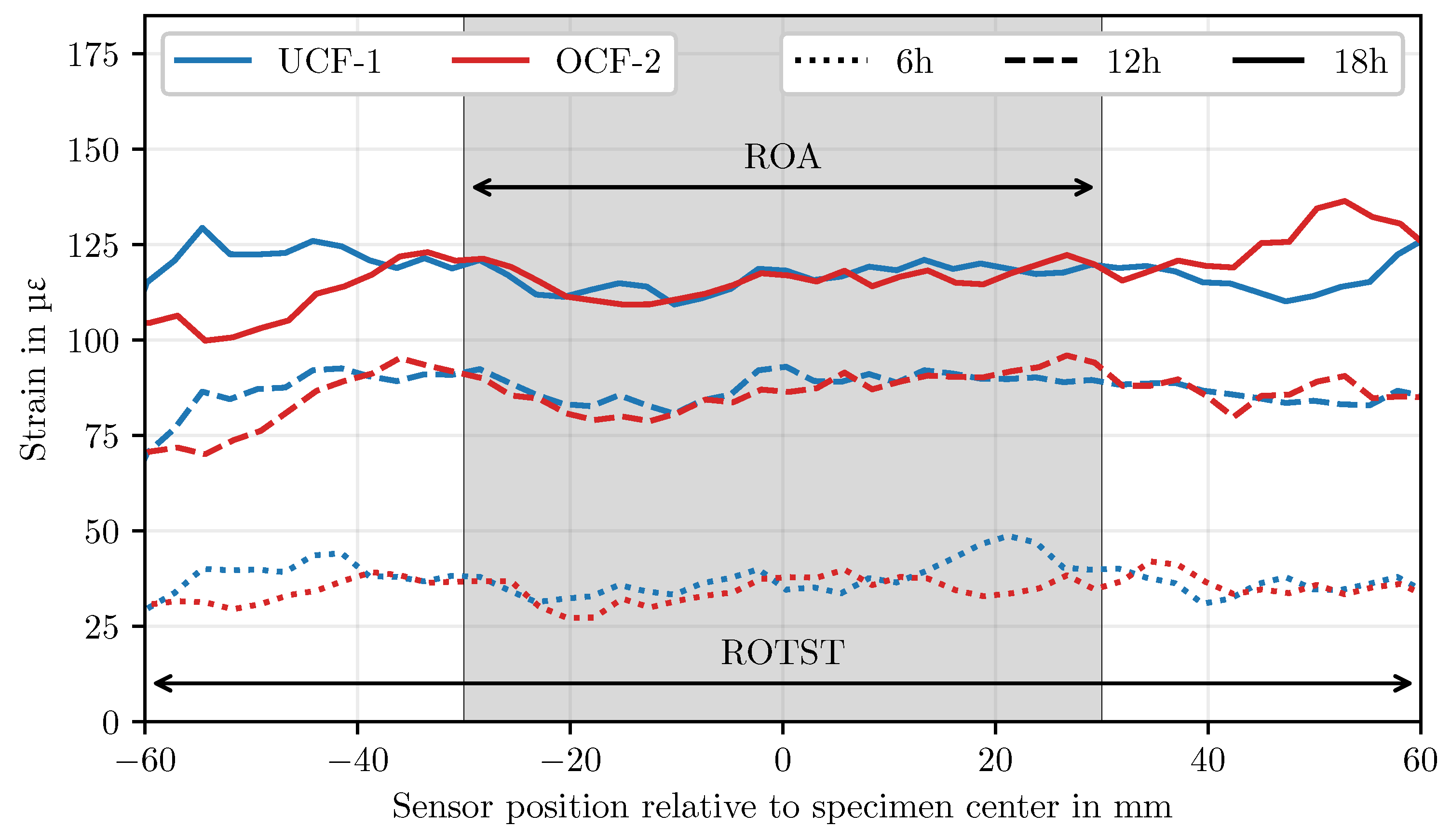
Figure 14.
Ambient temperature during the tests of specimens OCF-1 and OCF-2 compared to the mean of all OCF specimens.
Figure 14.
Ambient temperature during the tests of specimens OCF-1 and OCF-2 compared to the mean of all OCF specimens.
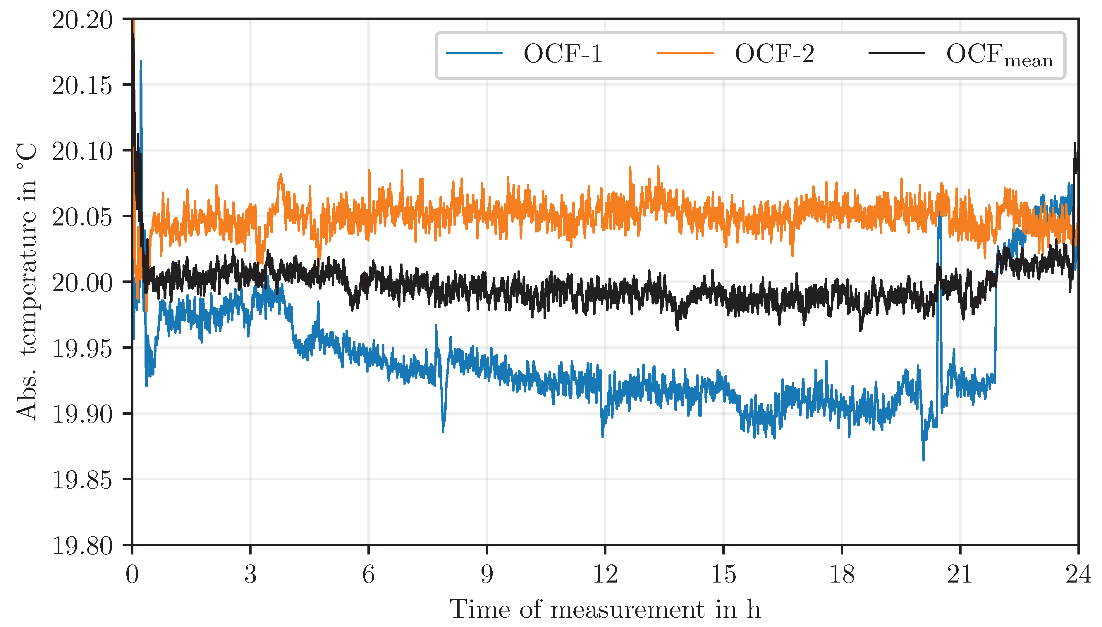

Table 1.
List of relevant measurement methods for the quantification of deformation in and on cementitious matrices.
Table 1.
List of relevant measurement methods for the quantification of deformation in and on cementitious matrices.
| Category | Measuring device | Example Source |
| unidirectional external | linear gauge | [46] |
| unidirectional external | DIC/DIP | [47,48] |
| unidirectional external | corrugated tube/PST | [41,49] |
| unidirectional external | laser-optic | [29] |
| unidirectional internal | FBG | [50,51,52] |
| unidirectional internal | DFOS | [22,25] |
| unidirectional internal | strain gauge | [53,54] |
| special | cone/laser-optic | [55,56,57] |
| volumetric | byancy method | [58,59] |
Table 2.
Mortar composition according to EN 196–1:2016.
| Component | Quantity in |
| 450 | |
| CEN Standard Sand | 1350 |
| Deionized water | 225 |
Table 3.
FOS characteristics.
| Description | Ormocer® | uncoatet |
| Notation | OCF | UCF |
| Fibertype | LAL–1550–125 | SMF–28 |
| Ø Core in | 9 | 9 |
| Ø Cladding in | 125(1) | 125(1) |
| Ø Coating in | 195 | – |
| Attenuation at 1550 in | <0.2 | |
| Strain coefficients in | −6.67 |
Table 4.
Test program: nomenclature and number of samples.
| Nomencl. | No. of spec. | Fibertype | Coating | Cover |
| UCF-X | 3 | SMF–28 | uncoated | PTFE, 1 mm |
| OCF-X | 8 | LAL–1550–125 | Ormocer® | PTFE, 1 mm |
| 1 | LAL–1550–125 | Ormocer® | uncovered |
Table 5.
Strain range and mean values of UCF and OCF at various measurement times.
| Time of measurement in h |
Avg. strain in | Range in | ||
| UCF | OCF | UCF | OCF | |
| 3 | −6.6 | 5.3 | 10.0 | 11.8 |
| 6 | 31.8 | 26.4 | 7.6 | 30.9 |
| 9 | 68.6 | 52.3 | 16.9 | 27.7 |
| 12 | 81.5 | 72.9 | 14.7 | 30.5 |
| 15 | 92.2 | 88.2 | 17.0 | 32.3 |
| 18 | 105.1 | 103.7 | 21.7 | 34.5 |
| 24 | 105.1 | 115.5 | 15.3 | 30.1 |
Disclaimer/Publisher’s Note: The statements, opinions and data contained in all publications are solely those of the individual author(s) and contributor(s) and not of MDPI and/or the editor(s). MDPI and/or the editor(s) disclaim responsibility for any injury to people or property resulting from any ideas, methods, instructions or products referred to in the content. |
© 2025 by the authors. Licensee MDPI, Basel, Switzerland. This article is an open access article distributed under the terms and conditions of the Creative Commons Attribution (CC BY) license (https://creativecommons.org/licenses/by/4.0/).
Copyright: This open access article is published under a Creative Commons CC BY 4.0 license, which permit the free download, distribution, and reuse, provided that the author and preprint are cited in any reuse.


