Submitted:
26 April 2025
Posted:
28 April 2025
You are already at the latest version
Abstract
In order to clarify the failure mechanism and ultimate bearing capacity calculation method of layered sand foundation under strip foundation, the finite element plastic limit analysis method is used to calculate and analyze the layered sand foundation, and the calculation results are compared with the existing test data and the calculation results of semi empirical formula, so as to verify the effectiveness of numerical calculation method and the deficiency of semi empirical formula. On this basis, multivariable analysis and calculation are carried out for layered sand foundation. Combined with the theoretical analysis method, the simplified calculation method of foundation ultimate bearing capacity corresponding to three failure modes, boundary and transition failure modes of foundation under strip foundation is given. The results show that according to the failure mechanism of the foundation, the failure forms of the foundation can be divided into punching shear failure, transition failure and general shear failure. The simplified calculation method of the ultimate bearing capacity of the foundation corresponding to the transition failure mode can be used as a reference for specific engineering design.
Keywords:
layered sand
; strip foundation
; bearing capacity
; failure mechanism
1. Introduction
Since Terzaghi [1] published a theory on the estimation of bearing capacity of shallow foundations on homogeneous foundations, many researchers have studied the bearing capacity of natural foundations. However, due to the complexity of the problem, it is still difficult to estimate the bearing capacity of shallow foundations on layered foundations, and the derived closed-form plastic solutions are cumbersome and highly inconvenient for engineering applications. In order to facilitate the use in practice, it is necessary to make some simple assumptions to derive a simple bearing capacity expression. Most of the existing relevant research results focus on dense sandy foundations on soft clay. Meyerhof [2] first used a semi-empirical method to calculate the bearing capacity of strip and circular foundations on dense sand over soft clay and also considered the case of sparse sand over hard clay. The punching and shearing model proposed by Meyerhof has since been improved in many experimental, numerical and analytical studies. Major improvements include the work of Hanna and Meyerhof [3], Griffiths [4], Das and Dallo [5], Michalowski and Shi [6], Kenny and Andrawes [7], Burd and Frydman [8], Okamura et al. [9], Shiau et al. [10], Qin and Huang [11], Salimi et al [12].
Compared with a single-layer sand foundation, the force transmission of a layered sand foundation is more complicated, and it is very difficult to obtain an analytical closed-form solution. Therefore, there has been relatively little research on the bearing capacity of shallow foundations on layered sand. The more classical methods are those in the Building Research Establishment Guide to Building Construction BRE470-2004 [13] and the semi-empirical method proposed by Hanna [14]. In fact, the method in BRE470 is a simplification of Hanna's method, which is based on Meyerhofs' punching and shearing model. Based on a specific simplified foundation failure model, researchers have used limit equilibrium and limit analysis methods to study the bearing capacity calculation of layered sand foundations. Ghazavi and Eghbali [15] extended the ground failure model proposed by Richards et al. [16] to derive bearing capacity factors for foundations on two layers of sand. For foundations on two layers of cohesive soil, Purushothamaraj et al. [17] obtained an upper bound analytical solution. Florkievicz [18], Huang Heqing [19], Khatri [20] and others use the finite element plastic limit analysis method (FELA) to calculate the upper and lower limits of the ultimate bearing capacity. The conic optimization method [21,22,23,24] can be used in combination during the calculation. In addition, the test results can also be used to study the bearing capacity of layered sand foundations. Hanna [14], Das and Munoz [25], and Kumar et al. [26] conducted scaled model test studies on layered sand foundations. However, considering the correlation between the mechanical properties of sand and the confining pressure stress level, the proportional effect may lead to an overestimation of the ultimate load [27,28]. Therefore, the results of the scaled model test cannot be blindly and directly applied to the full-scale foundation in the field, but the test results can be used to explore the failure mode and mechanism of the foundation.
In order to clarify the failure and destruction mechanism of layered sand soil foundations and the corresponding foundation bearing capacity calculation methods, and taking into account different geometric and soil mechanics parameters, a series of analyses were carried out using the finite element plasticity limit analysis method (FELA method) for layered sand soil. In addition to obtaining the upper and lower limits of the ultimate load, the variation of the foundation failure mechanism with geometric and soil mechanics parameters was also analysed. Based on a comparison with existing results, this paper proposes a practical method for determining the bearing capacity of strip foundations on stratified sandy soil foundations under transitional failure mode.
2. Punching Shear Model for Bearing Capacity Calculation of Layered Sandy Soil Foundations
The As mentioned earlier, Hanna [14] generalized the semi-empirical punching shear model proposed by Meyerhof [2] to the case of shallow foundations with loose sand overlain by dense sand. Foundation Along with the assumed upper sand layer shown in Figure 1, the failure cone is inserted into the underlying sand layer, and the underlying sand layer undergoes shear failure. The bearing capacity of the foundation includes the ultimate shear strength of the upper and lower sand layers. Specifically, the contribution of the upper sand layer is related to the passive pressure acting on the vertical failure surface shown in Figure 1, and its magnitude depends on the dynamic friction angle on the failure surface. Passive pressure can be expressed as:
Among them, indicates the severity of the upper sand layer; H and D indicates the thickness of the upper sand layer and the depth of the foundation burial, respectively; and Kp indicates the lateral earth pressure coefficient. The contribution of the bottom sand layer is equal to the limit bearing capacity qb of the virtual foundation on the homogeneous sand soil shown in Figure 1. Therefore, the bearing capacity qu of the strip foundation on the layered sand is:
where and denote the bearing capacities of a strip foundation on a uniform loose sand layer and a dense sand layer, respectively, and the corresponding embedment depths areand, respectively.
The inequality shown in Equation (2) indicates that the bearing capacity qu cannot exceed the bearing capacity of the foundation qt, which is located on a homogeneous, compact sand layer. Therefore, there should be a critical thickness Ha. Once Ha is exceeded, the properties of the underlying sand will not affect the bearing capacity of the foundation, and foundation failure will occur entirely in the upper sand layer. The bearing capacity factors Ny2、Nq2、Ny1 and Nq1 in Equations (3) and (4) can be calculated according to literature [29]. The calculation of Equations (1) and (2) is combined to obtain:
A very important parameter in the above formula is the dynamic friction angle, which is not constant but changes with the thickness of the upper layer of sand [2]. Hanna [14] used an experimental method to determine the parabolic distribution form, and the dynamic friction angle is a function of the relative shear strength of the two layers of sand. To simplify the bearing capacity estimation, Hanna borrowed Meyerhof's method and introduced a punching shear resistance factor, so that:
Equation (5) is transformed into:
Among them, the impact shear coefficient Ks can be obtained from the figure provided by Hanna [14], which is based on the angle of internal friction of the upper layer of sand and the angle of internal friction of the lower layer of sand. The method used in the BRE470-2004 guide is based on the punching shear model described above, with some conservative assumptions: 1. The depth of burial D is taken as 0 when calculating the contribution of the underlying sand to the bearing capacity, and the effect of the overloading factor is ignored. The dynamic friction angle is taken as , and the Coulomb passive earth pressure coefficient is used in item to calculate; ③The bearing capacity factor formula proposed by Vesic [30] is used, and the result of the formula is slightly greater than that proposed by Meyerhof [29]. When the thickness of the upper sand layer is less than the critical thickness, the bearing capacity value estimated by the BRE470-2004 guide method is always lower than the bearing capacity value obtained by Equation (5). This method can be used to quickly estimate the bearing capacity of layered sand foundations. However, a prerequisite for using this method is that the failure mode of the layered sand foundation is the punching shear mode, which does not necessarily match the actual engineering. If the thickness of the upper layer of sand is large enough, the failure mode should be the traditional shear mode, and there must be a transitional failure mode between the punching shear mode and the traditional shear mode. In addition, the foundation failure mode should be related to the relative strength of the two layers of sand, and it is also necessarily related to the thickness of the upper layer of sand. For this reason, the failure mode and bearing capacity calculation of layered sandy soil foundation is of great guiding significance for specific engineering design and is very necessary.
3. FELA Calculation of Load-Bearing Capacity
3.1. Calculation Parameters
The limit analysis method is a method for rigorously determining the upper and lower limits of the ultimate bearing capacity of a foundation [31]. The application of this method was initially limited to relatively simple problems, because complex geometries can lead to complex equations for which it is not easy to find an analytical solution. The application of limit analysis can be extended to complex geometries and heterogeneous soil strata [32] by solving the limit equilibrium equation using the finite element method. The corresponding method can be called the finite element plasticity limit analysis (FELA) method. This method can be used to solve for the upper and lower limits of the ultimate load, and the difference between the upper and lower limits can be understood as the error of the actual ultimate load. Assuming that the ultimate load is accurately solved as the average of the upper and lower limits, the relative error can be defined as [33]:
In this paper, the FELA method is used to calculate the bearing capacity of a strip foundation on layered sand. In order to reduce the relative error in the bearing capacity calculation, an adaptive remeshing technique is used [34]. The FELA method for analyzing the bearing capacity of foundations requires the assumption of plastic deformation in the sand and the constitutive model uses the associated flow rule. For the Mohr-Coulomb yield criterion, this means that the angle of expansion of the sand is equal to the angle of internal friction. Obviously, this assumption does not correspond to reality for granular materials. Although the assumption of the associated flow rule can affect the calculated value of the ultimate load, there is currently no quantitative analysis method for how much it affects the value. Davis [35] established a relationship between the limit load error caused by the associated flow rule and the degree of motion restraint. Drescher and Detournay [36] suggest using the equivalent strength parameters and the associated flow rule shown in Eqs. (9) and (10) to calculate the upper and lower limits of the ultimate load of geotechnical materials with unassociated flow.
Among them, 、 and c represent internal friction angle, expansion angle and cohesion, respectively, while 、 and f represent equivalent friction angle, equivalent expansion angle and equivalent cohesion, respectively.
A Mohr-Coulomb model and associated flow method are used for the double-layer sandy foundation, with the foundation lying on top of the surface sand. Coulomb friction is used between the foundation and the foundation, and the friction coefficient is taken as . To keep the relative error within 5%, four adaptive remeshing iterations are used in each analysis. The boundary conditions include fixed horizontal and vertical displacements at the base of the foundation and fixed horizontal displacements at the left and right boundaries of the foundation. According to Salgado et al [33], each model was solved twice to obtain the lower and upper limits of the ultimate bearing capacity, and the average ultimate bearing capacity was estimated accordingly. In addition, the mechanism of foundation failure can be determined based on the nodal velocity vector diagram and the contour map of power dissipation intensity. The area with high power dissipation intensity represents the plane of shear failure, and the nodal velocity vector diagram describes the mechanism of foundation failure [37]. The geometric and material parameters used in the calculation are shown in Table 1.
3.2. Calculation Error of Load Bearing Capacity
While keeping the remaining parameters unchanged, 、、 and , the upper sand thickness H and the lower sand internal friction angle increase. The upper and lower limits of the ultimate bearing capacity are calculated using the FELA numerical method combined with adaptive remeshing technology. The results are shown in Table 2. It is clear from the table that the relative error increases with the increase of the shear strength of the underlying sand, but it is still less than 5% of the control error. Therefore, the ultimate load can be approximated as the mean value of the upper limit and the lower limit , i.e. .
3.3. Comparison and Analysis of Calculation Results
In order to verify the validity of the FELA numerical calculation method and determine the scope of application of the existing semi-empirical formula, the FELA numerical calculation results are compared with the test results and the semi-empirical formula calculation results. Meyerhof and Hanna [38] and Das and Munoz [25] conducted physical model tests on layered sand. In the experiment by Meyerhof and Hanna [38], a strip foundation 0.05 m wide was used, with the base lying on the surface of the upper sand layer. The internal friction angles of the upper and lower sand layers were and , respectively, and the corresponding dry weights were and . The relative thickness of the upper layer ranges from 0.0 to 5.0. A comparison of the FELA calculation results with the test results is shown in Figure 2a. The test by Das and Munoz [25] used a 0.1016 m wide strip foundation, with the base lying on the surface of the upper sand layer. The internal friction angles of the upper and lower sand layers were and , respectively, and the corresponding dry unit weights were and , respectively. A comparison of the FELA calculation results with the test results is shown in Figure 2b. Figure 2a,b also list the comparison of the calculation results between Hanna's semi-empirical calculation method and the BRE470-2004 guideline method [14].
As shown in Figure 2a, the bearing capacity calculated by the FELA method is closest to that calculated by the Hanna method. When the relative thickness is satisfied, the test results agree well with the results calculated by the two methods. At that time, the BRE470 method calculated a relatively low value, but it was the closest to the test result. At that time, when the thickness of the upper sand layer was greater than the critical thickness, that is, when the failure occurred entirely in the surface sand, all three methods underestimated the bearing capacity of the foundation. This may be because a reduced-scale model test was used, and all three methods assumed that the internal friction angle of the sand does not change with depth. In fact, the surface layer of sand has a high friction angle due to its low consolidation stress, and the change in the friction angle with the average stress level is more obvious in dense sand [28]. Therefore, in the scaled model test, the foundation width is small, the corresponding critical thickness is also small, and even if the thickness of the upper sand layer exceeds the critical thickness, it is still relatively thin. In the three methods of calculation, it is assumed that the internal friction angle is constant, which obviously leads to a conservative prediction of the ultimate load. When , the contribution of the dense surface layer to the bearing capacity of the foundation is relatively small, so the nonlinear change of the friction angle of the sand (including the angle of expansion) with the average stress level has less of an effect. A similar conclusion can be drawn from Figure 2b. The critical thickness is reached when the bearing capacity does not increase further with the increase in the thickness of the upper sand layer. The critical thickness can be well obtained by the FELA method, and the critical thickness increases with the increase in the internal friction angle of the upper sand layer. Overall, the Hanna method overestimates the bearing capacity of the foundation, while the BRE 470 method underestimates it.
In order to clarify the bearing capacity of the layered sandy soil foundation, three typical foundation failure mechanisms shown in Figure 3, which were calculated by FELA, are selected. The velocity cloud diagram indirectly reflects the foundation failure mechanism. The three failure mechanisms shown in Figures 3a-c are:①1 Punching shear failure mechanism: This occurs when the shear strength of the upper sand layer is significantly higher than that of the lower layer, and the thickness of the upper layer is less than the critical thickness. This mechanism is basically the same as the failure mechanism considered by Hanna [14];②Transitional failure mechanism: between punching and shearing failure mechanisms and the general shearing failure mechanism;③General shear failure mechanism: the thickness of the upper sand layer is greater than the critical thickness.
The above analysis shows that the punching and shearing failure mechanism cannot describe all possible failure modes. Considering that there are relatively mature calculation methods for both punching and shearing failure and general shearing failure, it is necessary to propose a calculation method suitable for transition failure mechanisms.
4. FELA Calculation of Load-Bearing Capacity Transition Failure Mode
4.1. Transition Failure Mode Mechanism
In order to clarify under what circumstances the foundation failure mode will change from the punching shear mode shown in Figure 4a to the transition mode shown in Figure 4b, this paper performs a large number of FELA calculations as shown in Table 1, and determines the failure mechanism from the results of each analysis. Specifically, the ideal wedge-shaped formation under the foundation can be described by the inclination angle of the upper shear surface shown in Figure 4a, and the inclination angle can be calculated using the energy dissipation intensity isolines. The angle of inclination can be expressed as a function of the relative strength and relative thickness of the sand layer.
Among them, the unit of the inclination angle is degrees. a, b and c are parameters obtained by fitting a function to the FELA calculation results, as shown in Table 3.
The equivalent width is calculated according to formula in combination with formula (11) as shown in Figure 4a. When , the transition failure mode shown in Figure 4b may occur, i.e., appears in the punching and shearing failure mode. By statistically analyzing the FELA calculation results, the three failure modes shown in Figure 5 can be divided into zones, which can be used to identify the failure mode.
3.2. Transition Failure Mode Corresponding Foundation Bearing Capacity Factor
As shown in Figure 5, the three failure modes, the shear failure mode can be calculated using the Hanna [14] method, that is, Equation (7); the general shear failure mode can be calculated using the bearing capacity calculation method for homogeneous sand foundations; and there is no corresponding bearing capacity calculation method for the transition failure mode, so the corresponding bearing capacity can be defined as
Among them, represents the ultimate bearing capacity of the foundation when the thickness of the upper sand layer exceeds the critical thickness. The key lies in the calculation of the bearing capacity factor , which can be obtained by calculating the result of the FELA method. Formula (12) shows that the upper limit of the bearing capacity in the transition failure mode is the bearing capacity corresponding to the general shear failure mode. The FELA method calculation results show that is a function of 、、and .Considering that is approximately reasonable for engineering practice, the impact on M is not considered in this paper. The calculated changes in the transition and the corresponding load-bearing capacity factor are shown in Figure 6. This figure can be used to approximately estimate the load-bearing capacity factor corresponding to the transition failure mode.
5. Load-Bearing Capacity Determination Process
In summary, for layered sand foundations, the shear failure modes-punching shear failure, transition failure, and general shear failure-need to be determined before the bearing capacity of the foundation can be determined. The specific determination of the failure mode can be referenced in Figure 7. The bearing capacity of the hedge clipper when it fails can be calculated according to Equation (7); the bearing capacity of the transition failure mode can be calculated according to Equation (12); and the general failure mode can be calculated using traditional soil mechanics methods.
5. Discussion
This study employs finite element limit analysis (FELA) combined with adaptive mesh refinement to investigate the failure mechanisms and ultimate bearing capacity of layered sand foundations beneath strip footings. The numerical approach calculates upper and lower bounds of the bearing capacity, with an average relative error controlled below 5%. By comparing results with physical model tests and semi-empirical formulas (e.g., Meyerhof, Hanna, and BRE470 methods), the validity of FELA and limitations of existing empirical approaches are identified. A multivariable parametric analysis explores geometric and material parameters (e.g., layer thickness, friction angles) to categorize failure modes into three types: punching shear, transition, and general shear. A simplified method for calculating the bearing capacity under transition failure is proposed based on theoretical interpretations of velocity vector plots and energy dissipation patterns.
While the study provides valuable insights, several limitations warrant attention:(1)Assumption of Associated Flow Rule: The use of the Mohr-Coulomb model with an associated flow rule (dilatancy angle = friction angle) oversimplifies the non-associated behavior of sand, potentially overestimating shear strength [35,36]. Although corrections via equivalent strength parameters (Equations 9–10) are applied, the error magnitude remains unquantified;(2)Homogeneity of Soil Layers: The analysis assumes uniform soil properties within each layer, neglecting spatial variability and localized stress-dependent friction angle changes, particularly critical in thin upper layers under low confinement.(3)Scale Effects: Physical model validations rely on small-scale tests with inherent scaling discrepancies (e.g., stress level dependency of friction angles), limiting direct extrapolation to field-scale foundations [27,28].
(4)Simplified Transition Criteria: The boundary between failure modes (Figure 5) is derived empirically from finite parametric combinations, potentially omitting intermediate scenarios or complex layer interactions.
To enhance the robustness and applicability of the methodology, the following extensions are proposed:(1)Non-Associated Flow Analysis: Incorporate realistic dilatancy angles to refine shear strength predictions and quantify discrepancies caused by the associated flow assumption;(2)Full-Scale Field Tests: Validate numerical predictions against in-situ measurements to address scaling effects and stress-level dependencies;(3)Dynamic and Cyclic Loading: Investigate time-dependent effects such as cyclic loading or seismic excitations on failure mode transitions;(4)Machine Learning Integration: Develop predictive models using FELA-derived datasets to rapidly classify failure modes and optimize bearing capacity calculations.
6. Conclusions
In this paper, the FELA method is used to study the bearing capacity of layered sand foundations. Then, drawing on the research results of predecessors, theoretical analysis methods are used to study mainly the foundation failure modes and bearing capacity calculation methods. The results show that:
(1) The failure modes of layered sand foundations can be divided into punching shear failure, transition failure, and general shear failure. The transition failure mode occurs when the thickness of the upper sand layer is not sufficient to include the failure surface, but can include the conical failure cone.
(2) The Hanna method and the BRE 470 method are only applicable to the calculation of foundation bearing capacity under punching shear conditions, and the foundation bearing capacity calculated using the BRE 470 method is biased towards being conservative.
(3) The bearing capacity calculation method for layered sand foundations under transitional failure mode proposed in this paper can be applied in specific engineering design work.
References
- Terzaghi, K. Theoretical soil mechanics. London: Chapman and Hall; 1943.
- Meyerhof G, G. Ultimate bearing capacity of footings on sand layer overlying clay. Canadian Geotechnical Journal, 1974, 11(2): 223-229. [CrossRef]
- Hanna AM, Meyerhof GG. Design charts for ultimate bearing capacity of foundations on sand overlying soft clay. Can Geotech J 1980;17(2):300-3. [CrossRef]
- Griffiths, DV. Computation of bearing capacity on layered soils. Numerical methods in geomechanics. Proc., 4th int. conf. vol. 1. 1982. p. 163-70.
- Das BM, Dallo KF. Bearing capacity of shallow foundations on a strong sand layer underlain by soft clay.. Civ Eng Pract Des Eng 1984;3(5):417-38.
- Michalowski RL, Shi L. Bearing capacity of footings over 2-layer foundation soils. J Geotech Eng 1995;21(5):421-8. [CrossRef]
- Kenny MJ, Andrawes KZ. The bearing capacity of footings on a sand layer overlying soft clay. Geotechnique 1979;47(2):339-45. [CrossRef]
- Burd HJ, Frydman S. Bearing capacity of plane-strain footings on layered soils. Can Geotech J 1997;34(2):241-53.
- Okamura M, Takemura J, Kimura T. Bearing capacity predictions of sand overlying clay based on limit equilibrium methods. Soils Found 1998;38(1):181-94. [CrossRef]
- Shiau JS, Lyamin AV, Sloan SW. Bearing capacity of a sand layer on clay by finite element limit analysis. Can Geotech J 2003;40(5):900-15. [CrossRef]
- Qin HL, Huang MS. Upper-bound method for calculating bearing capacity of strip footings on two-layer soils. Yantu Gongcheng Xuebao/Chinese J Geotech Eng 2008;30(4):611-6.
- Salimi Eshkevari S, Abbo AJ, Kouretzis G. Bearing capacity of strip footings on sand over clay. Can Geotech J 2018.
- Working platforms for tracked plant. Good practice guide to the design, installation, maintenance and repair of ground-supported working platforms. BRE470 (Building research Establishment); 2004.
- Hanna, AM. Foundations on strong sand overlying weak sand. J Geotech Eng 1981;107(7):915-27. [CrossRef]
- Ghazavi M, Eghbali AH. A simple limit equilibrium approach for calculation of ultimate bearing capacity of shallow foundations on two-layered granular soils. Geotech Geolog Eng 2008;26(5):535-42. [CrossRef]
- Richards, M. Seismic bearing capacity and settlements of foundations. J Geotech Eng 1993;119(4):662-74. [CrossRef]
- Purushothamaraj P, Ramiah BK, Venkatakrishna Rao KN. Bearing capacity of strip footings in two layered cohesive-friction.
- soils. Can Geotech J 1974;11(1):32-45.
- Florkiewicz, A. Upper bound to bearing capacity of layered soils.. Can Geotech J 1989;26(4):730-6. [CrossRef]
- Huang M, Qin HL. Upper-bound multi-rigid-block solutions for bearing capacity of two-layered soils.Comput Geotech 2009;36(3):525-9. [CrossRef]
- Khatri V, Kumar J, Akhtar S. Bearing capacity of foundations with inclusion of dense sand layer over loose sand strata. Int J Geomech 2017;17(10):06017018. [CrossRef]
- HUANG YX, ZHAO QH, LIU JP. Preliminary study on influence of gravel soil compactness on horizontal bearing capacity of foundation. Yangtze River. 2019,50(05):180-184+204.
- Makrodimopoulos A, Martin CM. Upper bound limit analysis using simplex strain elements and second-order cone programming. Int J Numer Anal Methods Geomech 2007;31(6):835-65. [CrossRef]
- LIU T, LEI XW, MENG QS.Experimental study onhorizontal push-shear test of layered foundations of hydraulic fill reef sand.. Yangtze River. 2020,51(09):183-188.
- TANG Z,LUO Q, JIA H. Failure envelope of shallow strip foundation on sandy ground under slant loading.. Yangtze River. 2018,49(S2):291-293.
- Das BM, Munoz RF. Bearing capacity of eccentrically loaded continuous founda?tions on layered sand. Transp Res Rec 1984:28-31.
- Kumar A, Ohri ML, Bansal RK. Bearing capacity tests of strip footings on reinforced layered soil. Geotech Geol Eng 2007;25(2):139-50. [CrossRef]
- Hu ZH, W Y, LI DY. Experimental and theoretical study on bearing capacity of double artificial crust layers foundation formed by consolidation. Yangtze River.
- Cerato AB, Lutenegger AJ. Scale effects of shallow foundation bearing capacity on granular material. J Geotech Geoenv Eng 2007;133(10):1192-202. [CrossRef]
- Meyerhof, GG. Influence of roughness of base and groundwater conditions on ulti?mate bearing capacity of foundations. Geotechnique 1955;5(3):229-42.
- Vesic, AS. Bearing capacity of shallow foundations. In: Fang WA, editor. Foundation engineering handbook. New York: Van Nostrand Reinhold; 1975. p. 121-47.
- Drucker DC, Prager W, Greenberg HJ. Extended limit design theorems for con?tinuous media. Quart J Appl Math 1952;9:381-9.
- Sloan, SW. Geotechnical stability analysis. Geotechnique 2013;63(7):531-72.
- Salgado R, Lyamin AV, Sloan SW, Yu HS. Two- and three-dimensional bearing ca?pacity of foundations in clay. Geotechnique 2004;54:297-306.
- Lyamin AV, Krabbenhoft K, Sloan SW. Adaptive limit analysis using deviatoric fields. Proc. 6th int. conf. adaptive modeling and simulation. 2013. p. 448-55.
- Davis, EH. Theories of plasticity and failure of soil masses. Selected topics. New York: Elsevier; 1968.
- Drescher A, Detournay E. Limit load in translational failure mechanisms for asso?ciative and non-associative materials. Geotechnique 1993;43(3):443-56.
- Wilson DW, Abbo AJ, Salimi Eshkevari S, Sloan SW. Graphical interpretation of upper bound finite element limit analysis results. 15th int. conf. international as sociation for computer methods and recent advances in geomechanics, IACMAG. 2017.
- Meyerhof GG, Hanna AM. Ultimate bearing capacity of foundations on layered soils under inclined loads. Can Geotech J 1978;15(4):565-72. [CrossRef]
Figure 1.
Schematic diagram of punching shear failure.
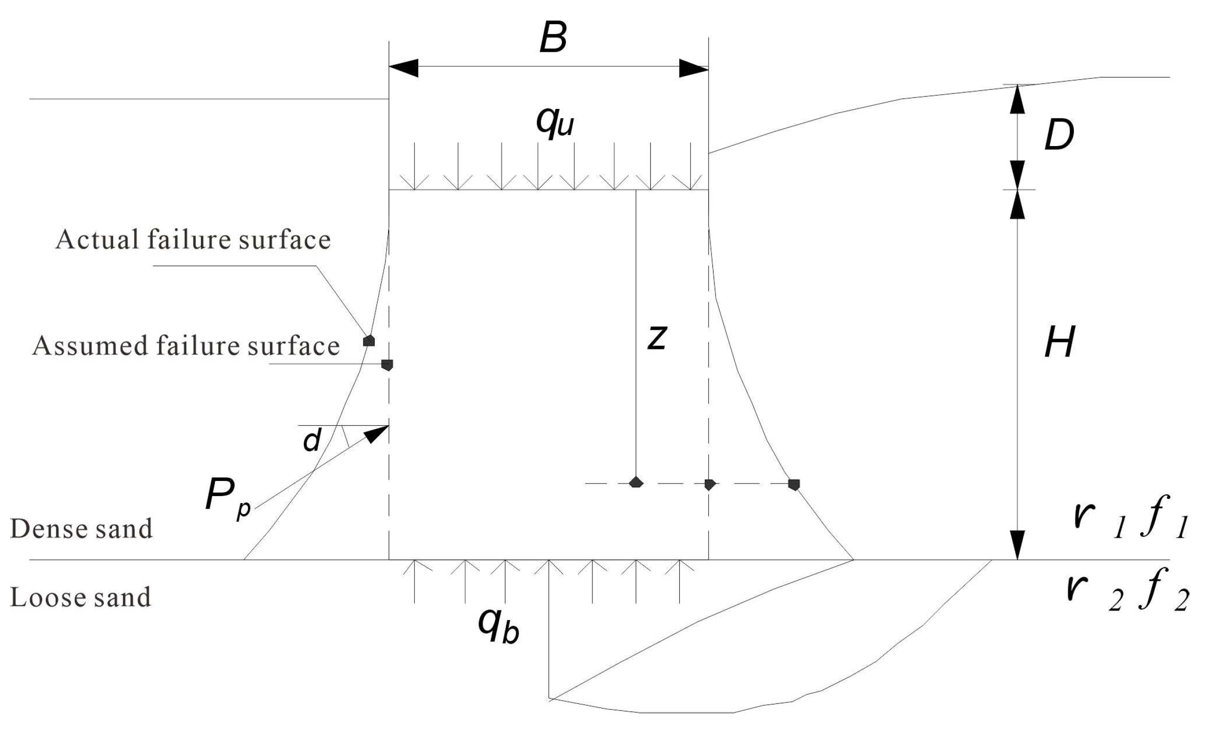
Figure 2.
Comparison of FELA calculation results with test results and semi empirical formula calculation results.
Figure 2.
Comparison of FELA calculation results with test results and semi empirical formula calculation results.
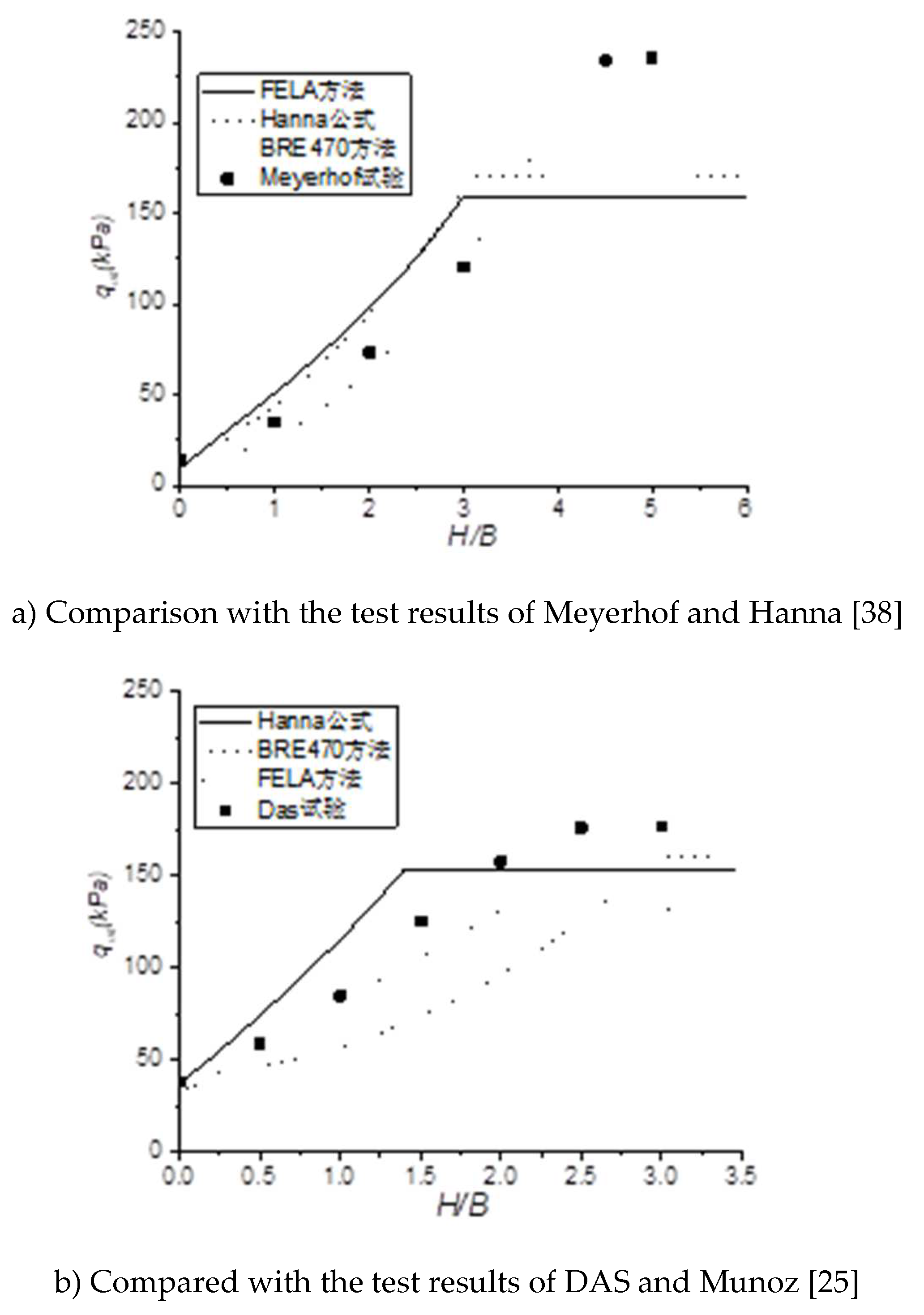
Figure 3.
Three failure modes of layered sand foundation.
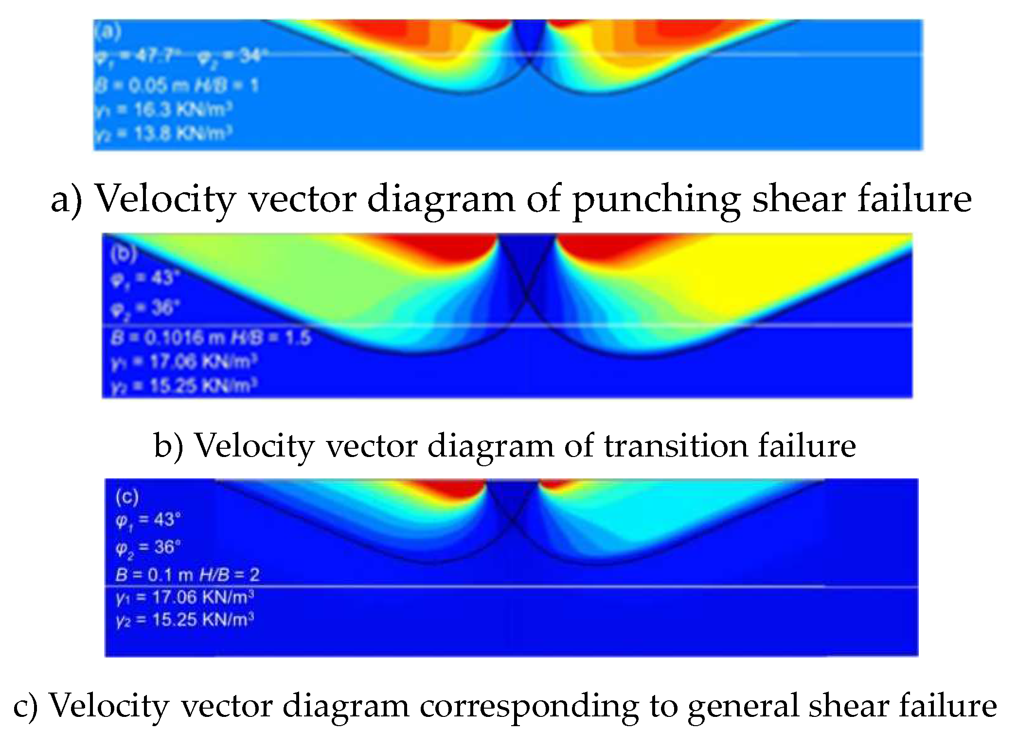
Figure 4.
Schematic diagram of two failure modes.
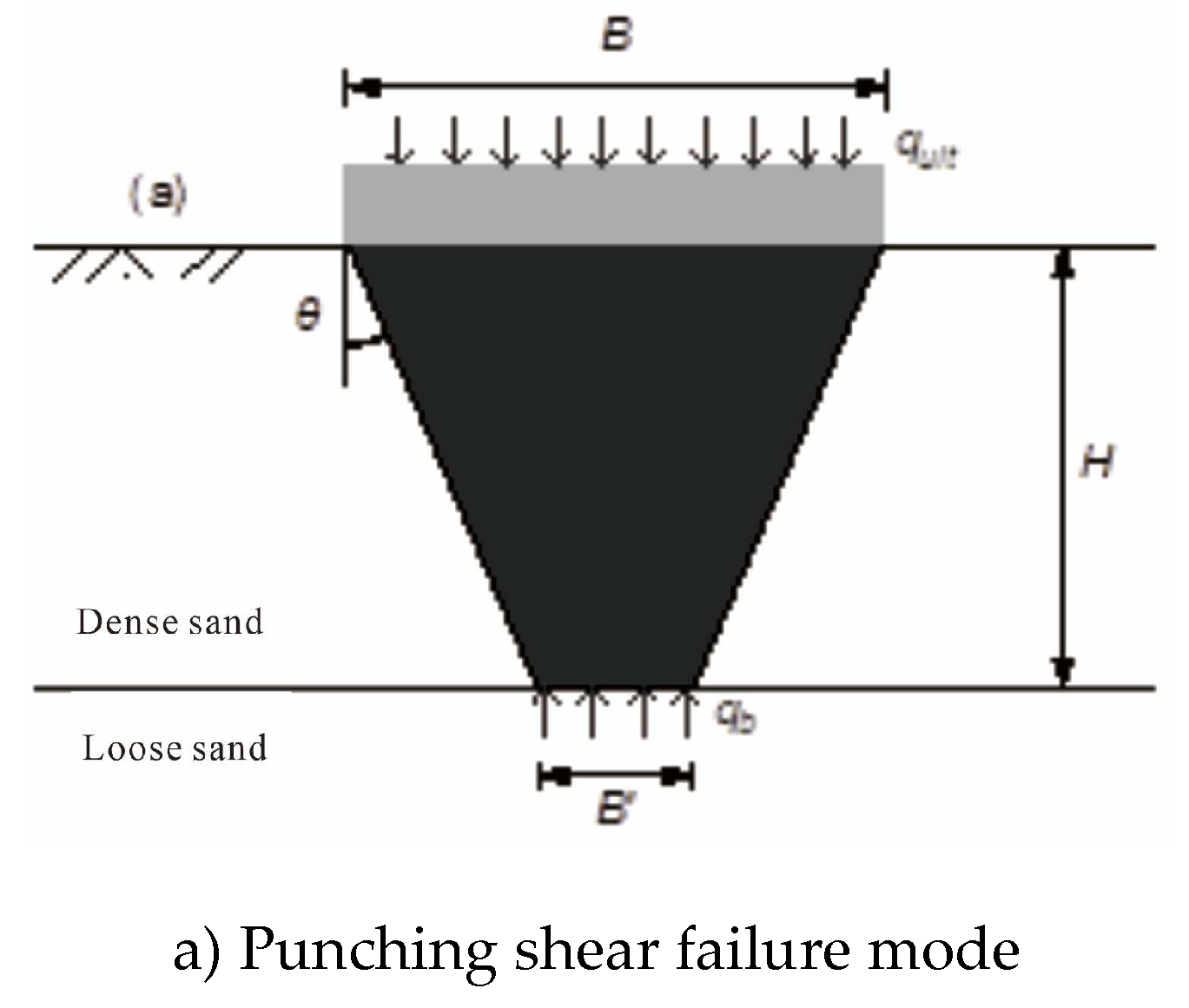
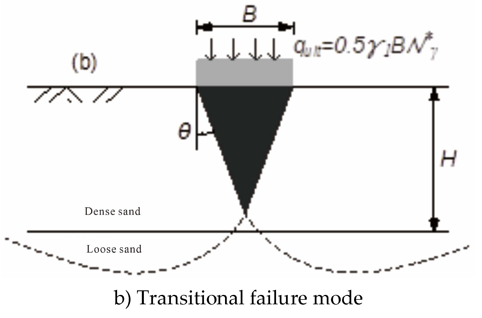
Figure 5.
Failure mode zoning.
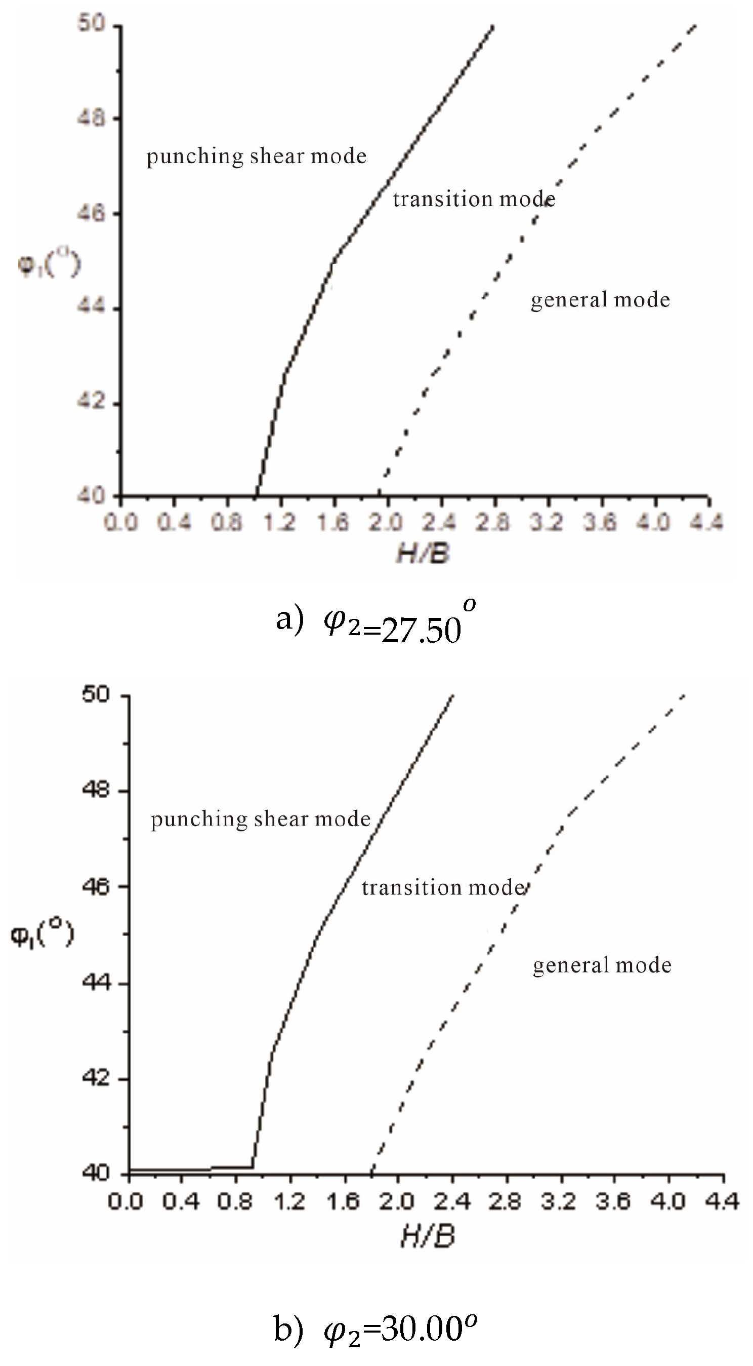
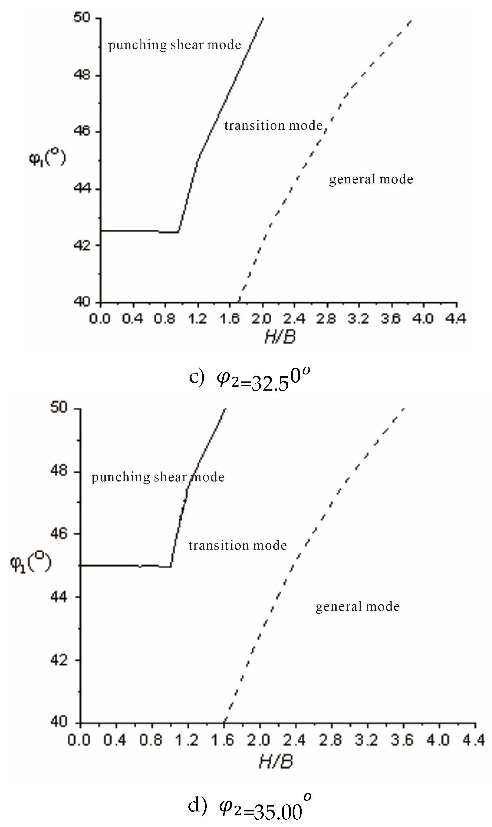
Figure 6.
Bearing capacity coefficient of foundation under transient failure mode.
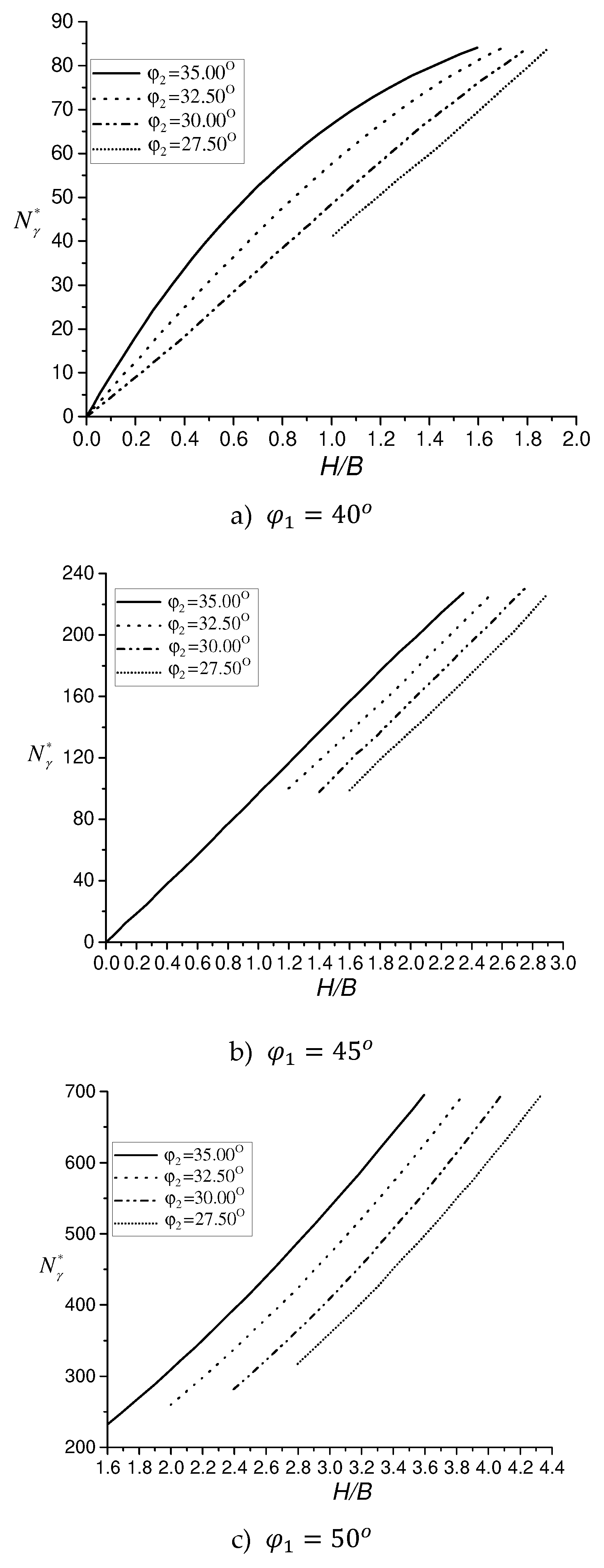
Figure 7.
Calculation process of bearing capacity.
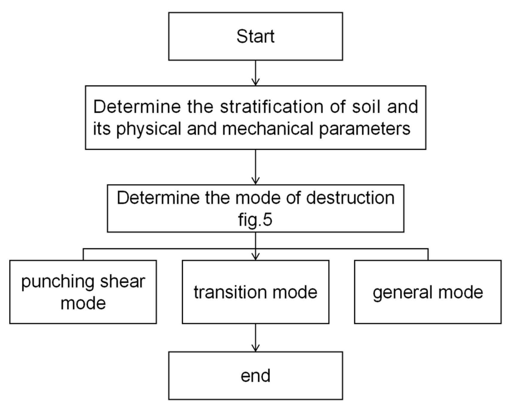

Table 1.
Calculation parameters of FELA method.
| Parameters | Value |
| (O) | 40.00 42.50 45.00 47.50 50.00 |
| (O) | 27.50 30.00 32.50 35.00 |
| (kN/m3) | 18.00 |
| (kN/m3) | 15.00 |
| 0.20 0.40 0.60 0.80 1.00 1.20 1.40 1.60 1.80 2.00 |
Table 2.
Calculation of upper and lower limits of ultimate bearing capacity and error by FELA method.
Table 2.
Calculation of upper and lower limits of ultimate bearing capacity and error by FELA method.
| (O) | (m) | (kPa) | (kPa) | (kPa) | (%) |
| 27.5 | 0.60 | 399.67 | 384.04 | 391.86 | 1.99 |
| 27.5 | 0.90 | 477.85 | 460.26 | 469.06 | 1.87 |
| 27.5 | 1.20 | 567.75 | 544.30 | 556.03 | 2.11 |
| 27.5 | 1.50 | 647.88 | 620.52 | 634.20 | 2.16 |
| 30.0 | 0.60 | 544.30 | 520.85 | 532.57 | 2.20 |
| 30.0 | 0.90 | 634.20 | 599.02 | 616.61 | 2.85 |
| 30.0 | 1.20 | 741.69 | 702.61 | 722.15 | 2.71 |
| 30.0 | 1.50 | 819.87 | 780.78 | 800.33 | 2.44 |
| 32.5 | 0.60 | 749.51 | 708.47 | 728.99 | 2.81 |
| 32.5 | 0.90 | 847.23 | 804.24 | 825.73 | 2.60 |
| 32.5 | 1.20 | 964.50 | 913.68 | 939.09 | 2.71 |
| 32.5 | 1.50 | 1046.58 | 985.99 | 1016.3 | 2.98 |
| 35.0 | 0.60 | 1046.58 | 985.99 | 1016.3 | 2.98 |
| 35.0 | 0.90 | 1146.25 | 1083.71 | 1115.0 | 2.80 |
| 35.0 | 1.20 | 1273.29 | 1197.07 | 1235.2 | 3.09 |
| 35.0 | 1.50 | 1343.65 | 1265.47 | 1304.6 | 3.00 |
Table 3.
Function fitting parameter table.
| (O) | a | b | c |
| 50.00 | 17.11 | -7.49 | 26.65 |
| 47.50 | 16.35 | -6.98 | 28.47 |
| 45.00 | 16.08 | -7.90 | 31.11 |
| 42.50 | 18.12 | -8.61 | 34.60 |
| 40.00 | 18.34 | -8.79 | 38.15 |
Disclaimer/Publisher’s Note: The statements, opinions and data contained in all publications are solely those of the individual author(s) and contributor(s) and not of MDPI and/or the editor(s). MDPI and/or the editor(s) disclaim responsibility for any injury to people or property resulting from any ideas, methods, instructions or products referred to in the content. |
© 2025 by the authors. Licensee MDPI, Basel, Switzerland. This article is an open access article distributed under the terms and conditions of the Creative Commons Attribution (CC BY) license (http://creativecommons.org/licenses/by/4.0/).
Copyright: This open access article is published under a Creative Commons CC BY 4.0 license, which permit the free download, distribution, and reuse, provided that the author and preprint are cited in any reuse.


