Submitted:
25 March 2025
Posted:
26 March 2025
You are already at the latest version
Abstract
Restrike frequently occurs in positive leader development of long air gap discharges. However, its detailed physical process and mechanism remains unclear. For the purpose of studying the physical mechanism of Restrike, experiments were conducted in a 6-meters rod-plane air gap under positive impulses with the crest time of 1000µs, and the process of Restrike was observed during discharge. Experimental results showed that significant luminescence appeared at the tip of the leader channel during a relatively longer time of discharge relaxation process before Restrike, and the luminescence became more and more intense with the increasing of applied voltage until Restrike occurred. By analyzing the charged particles composition inside the leader channel, this paper infers that during the relaxation process, the positive ions inside the leader channel migrate and concentrate towards the leader channel tip as the applied electrical field increasing, and the concentration of positive ions at the leader channel head distort and enhance the local field, which then induces the streamer corona discharge and lead to the luminescence of the leader channel. The observation evidence and analysis may provide valuable reference for a better understanding of the physical mechanism of Restrike.
Keywords:
positive
; long air gap
; discharge
; restrike
; relaxation process
; leader channel
; re-illumination
1. Introduction
Positive leader discharge of long spark usually launches from the energized anode, it includes four main stages before it bridges the cathode, the first corona formation, the streamer to leader transition, the leader development and the final jump [1,2,3]. Generally speaking, with the increase of the applied voltage subjected to the gap, the leader develop forward continuously with a little change current and velocity until the gap is broken down. However, the leader often behaves noticeable discontinuous development with a relatively long front time of the applied voltage or at a high ambient humidity, the leader channel brightens and elongates abruptly with a powerful glaring corona streamer burst at its tip [4,5], and are associated to a sharp current pulse, this phenomenon is often called restrike or Re-illumination [3,6]. The discontinuous development of positive leader exists both in the discharge process of natural lightning and long air gap discharges under laboratory conditions [7,8].
Although it has been a long time in researching the long air gap spark, the study focusing on restrike is relatively few, and the explanation of physical mechanism about restrike is still very challenging. In the field of electrical engineering, air gap is usually used as the main external insulation way for UHV transmission and transformation systems, and the front time of switching overvoltage generated during operation can reach more than 1000 μs [9]. Under the action of overvoltage, the flashover of air gaps with the gap distance of several meters is often accompanied by restrike, which in turn affects the flashover characteristics of the air gaps in UHV transmission and transformation systems [10,11]. Therefore, it is of great engineering research value to clarify the physical process and mechanism of the positive restrike in long air gap spark, or improving the existing positive leader development models, and guiding the refined design of external insulation in ultra-high voltage transmission projects.
Since the 1970s, scholars from various countries have conducted a series of theoretical or experimental studies on positive leader restrike. The Les Renardi è res Group team in France found in a laboratory environment that the probability of restrike occurring during discharge significantly increased as the humidity exceeded 8-10 g/m3 [3]. Restrike phenomenon often occurs with sudden elongation of the leading channel, sudden increase in discharge current, and sudden enhancement of channel luminescence. Baldo and Rea classified the restrike phenomenon into two types: "bell shaped" and "steep rise" based on the similarity between the channel discharge current waveform and the channel emission pulse during the occurrence of restrike [12,13]. In 1986 [14], Les Renardières Group conducted a "simulated" experimental study on restrike phenomenon by applying positive and negative switching impulse voltages of opposite polarity to a 6m rod-plate air gap at different times, with the help of schlieren system, the dissipation and activation of the leader channel during discharge relaxation were observed, and the experimental results indicated that there was no luminescence in the leader channel during the discharge relaxation stage. Further more, during the discharge relaxation stage, the original channel was reactivated as the electrode applying a negative voltage impulse, this phenomenon was very similar to the restrike observed in long air gap discharge, so this experiment was also called as the "artificial restrike" by Ref. [15]. In Ref. [15], Domens et al. observed the restrike by applying positive impulse to a 16.7m rod-plate air gap, they found that the discharge current always disappeared for a period of time before the discharge activity resumed, this is consistent with the observation results of the "steep" type restrike phenomenon [3].
At the same time, Domens et al. employed a high-speed schlieren system to observe the leader channel near the tip of the electrode during the positive discharge process with a gap distance of 2.2m [16]. It was found that before the restrike occurred and during the discharge relaxation process with the discharge current of I=0, the insulation characteristics near the electrode tip was restored for a certain period of time, and the original leader channel no longer connected to the electrode. In recent years, researchers conducted in-depth experimental study on the influence of humidity on the discontinuous development of leaders, the pulse characteristics of restrike current, the charge amount, the leader development speed, etc [7,8,17,18]. Nevertheless, the restrike phenomenon and its physical process during the discontinuous development of leaders have been overlooked.
In this paper, by constructing a synchronous observation experimental platform for long air gap discharge, the positive switching impulse with a wave front time of 1000 µs was applied to a 6 meters rod-plate gap. The "steep" type restrike during the discharge process was observed, and the luminescence phenomenon of the leader channel during the relaxation process before the occurrence of restrike was studied and analyzed. Finally, based on the experimental results, the physical mechanism of the luminescence phenomenon generated by the leader channel during relaxation process was preliminarily explored.
2. Experimental Set-Up and Conditions
The experimental set-up for synchronous observation of long air gap discharge constructed in this paper is presented in Figure 1. In order to generate the restrike during the discharge process, it is necessary to apply the voltage impulse with long front time to the air gap. Therefore, by configuring reasonable head resistance and capacitance, the Marx generator generated switching impulse with the front time of 1000 μs, which was then directly delivered to the rod-plate gap with a gap distance of 6 m. The rod electrode tip was hemispherical, with a diameter of 2 cm and an end - curvature radius of 1 cm. The plate electrode was made of aluminum with the size of 30 m×30 m and was well grounded.
It should be mentioned that the upper end of the rod electrode was a hollow cylinder, in which a transient current acquisition system was installed. The structure and principle of this acquisition system are consistent with those described in reference [19], and it could achieve the discharge transient current acquisition with the peak current of 600 A, the bandwidth of 0-70 MHz, and the time resolution of up to 2ns [20], and it could sensitively and finely reflect the current characteristics during the discharge process. The output voltage impulse of the Marx generator was sent to an oscilloscope with the model of DPO-4104B through a capacitor divider with a voltage division ratio of 1:5358. After capturing the switching wave voltage pulse, the oscilloscope output a synchronous trigger signal, which was then sent to the current acquisition device and the CCD high-speed camera respectively through an electro-optical converter to achieve the synchronous acquisition of the discharge voltage, current, and the optical morphology of leader channel during the discharge process.
The optical morphology of the leader channel during the discharge development process was photographed by a high-speed camera of model FASTCOM SA5. Due to the short duration of the discharge development and the relatively long distance between the high-speed camera and the rod-plate gap, in order to simultaneously take into account the spatio-temporal resolution of the high-speed optical photographs, the camera’s shooting speed was set to 200,000 frames per second (fps), with an exposure time of 4 μs per frame and a spatial resolution of 152 pixels×256 pixels. Since the luminescence of the leader channel was weak, in order to avoid the interference of external light and capture the discharge development process of the leader channel more clearly, the experiment was conducted at night. The ambient temperature during the experiment was 17°C to 23°C, and the relative humidity was 62% to 78%, the atmospheric pressure was 1 atm.
3. Experimental Results
3.1. Gap Withstood
The typical experimental observation results when the gap withstood are shown in Figure 2. Specifically, Figure 2a displays the waveform of discharge voltage and discharge current, while Figure 2b presents partial high-speed optical photographs capturing the initiation and development process of the leader. In order to highlight the characteristics of important electrical parameters, only the first 800 µs of the voltage and current waveform are presented in Figure 2a. When the switching voltage was applied to the gap, the positive electrode generated an initial corona discharge at t=19.71 µs, with a pulse amplitude of 2.45A. Subsequently, under the suppression effect of the positive space charge in streamer region near the electrode tip, the discharge ceased. After a dark period of approximately 23 µs, the leader initiated at t=42.35 µs and continuously propagated towards the middle of the gap. However, the continuous development current of the leader at this time was relatively small, approximately 0.1- 0.2 A. Starting from t=136.65 µs, the leader began to enter the discontinuous development stage. After that, seven typical restrikes occurred.
Among them, the current pulse amplitudes of the two restrikes at t=373.74 µs and t=499.33 µs reached 8.32 A and 11.6 A respectively. After that, before the front time of the voltage wave ended, the development of the leader channel had already ceased and the gap withstood the voltage.
As can be seen from the current waveform in Figure 2 that all the restrikes appearing during the discharge development process were the type of “steep rise” . During the discharge relaxation stage between every two restrike current pulses, the discharge current was basically zero, and the duration of the relaxation process varied. Among them, the relaxation time between the 5th and 6th restrike pulses was the longest, being 71 µs and 100 µs, respectively, and the corresponding current pulse amplitudes were also the largest.
In order to clearly observe the current characteristics and the luminous characteristics of the leader channel before and after the occurrence of the restrike, high-speed camera photographs and current waveform corresponding to the 5th (t=373.74 µs) and 6th (t=499.33 µs) restrike in Figure 2 were extracted, as illustrated in Figure 3. The six high-speed pictures before and after the occurrence of these two restrikes were named F1 – F6 and F7 – F12 respectively, the start and end moments of the exposure of each frame were corresponding to the time axis of the discharge current waveform with dashed lines.
Due to the limited resolution of the high-speed photographs in Figure 3, in order to highlight the details of the optical characteristics of the leader channel before the occurrence of restrike, the high-speed optical photographs in Figure 3 had been processed with the image pseudo-color algorithm [21]. That was, as the grayscale value of the image increases, the color of which would gradually change from blue to red, and it would turn white when the grayscale value was extremely high. In addition, the area where the leader channel was located in the photograph was marked with a white dotted frame, and the area within the white dotted frame was magnified three times and placed below the picture.
As can be seen from the current waveform of the discharge shown in Figure 3, within 25 – 30 µs before the arrival of the restrike pulse, the leader discharge current was almost zero, indicating that the leader channel had stopped developing and entered the discharge relaxation stage, and the ionization activity of the streamer region at its head had ceased . At the two moments of t=373.90 µs and t=499.87 µs, the restrike phenomenon occurred, and the current of the discharge channel suddenly increased. However, within 20 µs, the continuous current of the leader decayed to zero, and the discharge entered the relaxation stage again.
Judging from the four photographs before the two restrike pulses shown in Figure 3, during the process of gradually approaching the restrike moment, there is a luminous phenomenon in the leader channels in all four pictures, and it is constantly intensifying, making the shape of the original leader channels more and more obvious. Especially, the leader channels on the right side of the branch in picture F5 before the restrike phenomenon in Figure 3a and the leader channels on the left side of the branch in picture F11 in Figure 3b are particularly luminous.
Judging from the four photographs before the two restrike current pulses shown in Figure 3, during the process of gradually approaching the restrike moment, the leader channels in all four photographs exhibited luminescence phenomena, which were constantly intensifying, making the shape of the original channels more and more obvious. Especially the leader channel on the right side of the branch in F5 before the restrike of Figure 3a and the leader channel on the left side of the branch in F11 of Figure 3b were particularly luminous.
However, the discharge current corresponding to the exposure time of these two photographs could be almost ignored. If the observation time was advanced by another 5 µs, it could be clearly seen in photographs F4 and F10 that there was obvious luminescence at the channel head , while the luminescence in the middle and upper ends of the channel was relatively weak or even non-existent. Moreover, the corresponding current during the exposure time of these two images was still zero. The current waveform and high-speed optical photographs in Figure 3 indicated that there might be discharge phenomena at the head of the leader channel during the discharge relaxation process before restrike occurred.
3.2. Gap Breakdown
The typical experimental results of gap breakdown are shown in Figure 4. In this discharge, the initial corona started at t=20.29 µs. After developing for a certain period of time, it stopped developing when the first restrike occurred at t = 140.67 µs. After six restrikes with larger current pulse amplitudes, the leader channel continued to steadily develop until the gap broke down. In the 7 restrikes, the current amplitudes of the 4th and 7th restrikes were significantly larger than those of the other 5 restrikes, with peak values reaching 6.05 A and 12.36 A, respectively.
Select the current pulses around the moments when the 4th (t = 290.37 µs) and the 7th (t = 519.89 µs) restrikes eventsr, as well as the corresponding 7 frames of high-speed optical photographs. Each frame of photograph was named as F1’ – F7’ and F8’ – F14’ respectively, as shown in Figure 5a,b. During the relaxation stage before the restrike pulse shown in Figure 5a, the luminosity at the head of the leader channel was relatively weak. It gradually became clear starting from picture F3’ (The unclear optical morphology in F5’ was due to the occurrence of restrike at the upper end of the electrode, and the intense luminosity caused the camera to automatically reduce the ISO sensitivity. Meanwhile, the current formed by discharge of the shielding cylinder on the upper part of the electrode did not enter the internal current sensor, so there was no change in the current on the current waveform).
However, during the discharge relaxation stage shown in Figure 5b, the luminosity at the head of the leader channel was very obvious. Looking at the currents corresponding to the pictures, except for a very small discharge current (I < 0.1A) near the end of the exposure time of photograph F12’, the discharge currents corresponding to the first four frames of photographs were all zero. The phenomena above are basically consistent with those observed in Figure 3a,b.
4. Discussion
4.1. Relationship Between Restrike Current Pulse Peak and Relaxation Time
In long air gap discharges, when the wavefront time of the applied voltage is long and the rate of rise of the electric field applied to the HV. electrode is lower than the rate of rise of the space charge electric field generated by the ionization in the streamer region near the leader tip, the activity level of the streamer region will significantly weaken or stop ionization. In addition, when the ambient humidity is relatively high, the ionization efficiency of the streamer region also decrease significantly due to the strong affinity of water molecules for electrons. In the experiments of this paper, the switching pulse with the wavefront of 1000 µs was applied to the gap, the corresponding voltage rise rate was relatively low. Coupled with the relatively high ambient humidity, the frequency of restrike during discharge process was high. When the streamer region at the leader head gradually weakens until the ionization stops, it can no longer continue to inject electrons into the leader channel. Meanwhile, the high-temperature gas molecules in the channel continuously undergo convection with the gas molecules in the surrounding environment, causing the temperature of the channel to keep dropping. This further leads to the decrease or cessation of the thermal disassociation within the channel, resulting in the discharge current of the leader dropping to zero and entering the relaxation stage.
Statistical analysis of the experimental observation results showed that the luminous phenomenon at the leader head could not be clearly seen every time in the relaxation process. A total of 18 discharges were carried out in this experiment, and the number of restrikes in each discharge varied from 1 to 7 times. In total, about 74 relatively obvious restrike current pulses were generated in 17 times of discharge. According to the high-speed camera pictures of the discharge process, 34 discharges exhibited luminescence at the head of the leader channel during the relaxation process before the occurrence of restrike. The relationship between the peak values of these 34 restrike current pulses and the duration of the relaxation phase before the occurrence of restrike is shown in Figure 6, where the red dotted line represents the linear fitting result of the relationship between the two.
It can be seen from Figure 6 that, due to the high dispersion of long-gap discharges, when there is luminescence at the head of the leader channel during the relaxation process, there is no obviously linear relationship between the corresponding relaxation time and the peak value of the restrike current pulse that follows immediately. However, judging from the overall trend of change, as the relaxation time increases, the peak value of the restrike current pulse shows a relatively obvious increasing trend. Under the experimental conditions described in this paper, when the peak value of the current pulse exceeds 5A and the time of the relaxation stage is greater than 40 - 50 µs, the frequency of the luminescence occurring at the head of the leader channel before the restrike is relatively high. According to the corresponding high-speed optical photographs, when the relaxation time is relatively short (< 40 µs), the luminescence at the head of the leader channel is not obvious. Relatively speaking, when the relaxation time is longer, the luminescence at the head of the channel is more obvious, and the luminous intensity increase significantly with the passage of the relaxation time, while the peak value of restrike current pulse is also larger.
4.2. Luminescence of the Leader Channel During Relaxation Process
According to the previous efforts of long spark, during the relaxation process of the leader channel before the occurrence of restrike, there is no obvious ionization activity at the head of the channel, and the channel does not show obvious luminous phenomena either [3]. However, the high-speed pictures shown in Figure 3 and Figure 5 and the corresponding current waveforms indicate that during the relaxation process before the occurrence of restrike, although the discharge current measured at the high-voltage electrode is zero, the leader channel exhibits a certain degree of weak luminescence, that is, "the dark period is not actually dark", which indicates that during the relaxation process before the occurrence of restrike, ionization activities may take place in the leader channel, and a large number of photons are emitted simultaneously. Moreover, as the relaxation process progresses, the number of photons gradually increases towards the moment of restrike occurrence. However, restricted by the limited time resolution of the high-speed camera, within a few microseconds before the leader restrike occurred, although there might still be other forms of ionization in the channel, it was impossible to conduct a more detailed observation of this discharge development process.
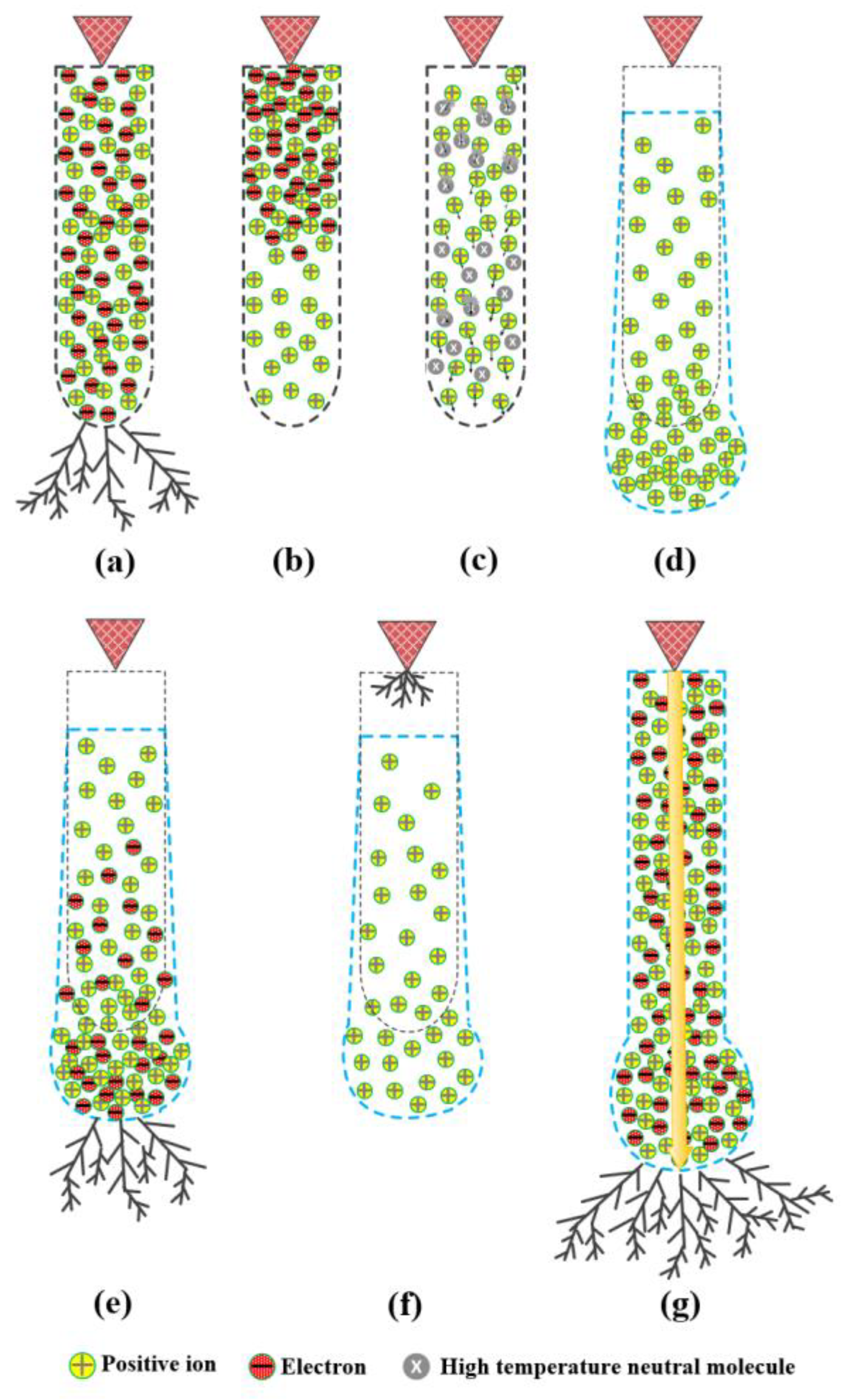
The widely recognized critical temperature for for the streamer-leader transition is 1500-2000K [3,22], which is the critical temperature for the dissociation of a large number of negative ions inside the streamer stem. During the continuous development of the leader channel, its axial temperature can reach above several thousands of Kelvin[3,23], which is much higher than the critical temperature 1500-2000K of negative ion dissociation. Under the effect of the high temperature in this channel, the negative ions within the leader channel are dissociated into neutral particles and free electrons, making the density of free electrons in the leader channel far greater than that of negative ions [4,24]. Therefore, this paper holds that during the continuous development of the leader, the charged particle components inside the leader channel are mainly free electrons and positive ions, and the density of negative ions can be basically ignored, this is quite different from the previous literature[8] which held that in addition to positive ions, there were also negative ions and electrons inside the channel. The schematic diagram of the charged particle components of the channel in this stage is shown in Figure 7s. Under certain external conditions, when the streamer region at the leader head stops ionizing and the discharge enters the relaxation stage, the number of electrons inject into the channel decreased sharply, causing the conductivity of the channel to drop rapidly. Meanwhile, the channel voltage drop and the electric field inside the channel may increase rapidly. The schematic diagram of this instantaneous process is shown in Figure 7b. Subsequently, under the action of the increasing electric field within the channel, the residual electrons migrate into the anode rapidly, making the charged particle components within the channel mainly positive ions. Therefore, the leader channel at this time may not be a true plasma channel.
Under the effect of the externally applied electric field in the gap, the positive ions within the leader channel migrate towards the channel head along the direction of the electric field and collide with the high-temperature neutral molecules inside the channel, as illustrated in Figure 7c. Through the momentum exchange during collisions, the high-temperature neutral molecules in the channel gradually move away from the root of the channel along with the positive ions, resulting in a continuous reduction in the number of high-temperature gas molecules in the discharge channel originally connected to the electrode tip. With the passage of time, the gas temperature near the electrode gradually decreases to be consistent with the environment, and the gas density of the channel also increases to be the same as that of the surrounding gas, making the original leader channel appear to be "disconnected" from the high-voltage electrode [16], as shown in Figure 7d, where the black dashed line represents the bottom edge of the leader channel, while the blue dashed line represents the edge of the channel after "disconnected" from the electrode.
Due to the high gas temperature and low density within the channel, the mobility of positive ions in the channel is greater than that at ambient temperature, and therefore they can migrate and accumulate towards the the channel head more quickly under the external electric field. According to the Schlieren observation results and simulation analysis of the leader channel during the relaxation process in Reference [25], it can be concluded that as the positive ions migrated and accumulate towards the leader head, the leader head further extends forward, and the radius range of the head region also increases further, as shown by the blue dashed line at the leader head in Figure 7d, this is also different from the schematic diagram shown in Figure 6 of Reference [8]. Subsequently, the Poisson field formed by the aggregated positive ions superimpose with the externally applied electric field in the gap, causing the distortion and enhancement of the local electric field in the area near the head of the original discharge channel. While this superimposed electric field reaches the electric field threshold of 26-30 kV/m in air [2,3], the streamer region near the channel tip reactivates and makes photons emitting. The schematic diagram is shown in Figure 7e. Under the action of the electric fields both inside and outside the channel, the electrons generated in streamer region at the channel head directly inject into the channel and then quickly recombine with the positive ions in the channel, and release a large number of photons, causing the channel head to exhibit the channel luminescence phenomenon during the relaxation process before restrike as shown in Figure 3 and Figure 5.
Because of the high density of positive ions inside the channel, the electrons entering the channel through streamer discharge neutralize directly with the positive ions or attach to neutral particles to form negative ions, and then recombine with the positive ions during the migration towards the high-voltage electrode. Therefore, they basically can’t directly enter the high-voltage electrode from the inside of the channel. Consequently, in Figure 3 and Figure 5, before the occurrence of restrike, although there was discharge and luminescence at the channel head, the current measured at the high-voltage electrode was basically zero.
As the externally applied electric field further increases, the local electric field in the head region of the leader channel increases accordingly, and the streamer discharges generated thereby become more and more intense. Therefore, it can be seen from Figure 3 that compared with F4, F5 showed a larger luminous range and more obvious luminous intensity formed by the streamer discharge at the channel head, and the same as F11 compared with F10 or F9. Similarly, in Figure 5, the discharge and luminescence at the channel head were also the same for F12'compared with F11'.
Although the Poisson field formed by the positive ions in the channel have a certain inhibitory effect on the external electric field generated at the high-voltage electrode, with the continuous increase of the applied voltage and the continuous migration of the positive ions towards the channel head, the electric field at the tip of the electrode becomes larger and larger. After it reaches the breakdown electric field threshold of 26 - 30 kV/m, new streamer discharges restarts at the electrode, as shown in Figure 7f. And then, the leader discharge formed by the streamer discharge rapidly develops forward along the thermal imprint of the original channel and quickly extends to the channel tip at a speed of about 108 cm/s [3], resulting in the occurrence of restrike and the re-connection to the electrode of the channel. The schematic diagram is shown in Figure 7g. At this point, the discharge current suddenly increases drastically, forming the restrike current pulse with the peak value of several amperes. The leader channel reconnects to the high-voltage electrode, and the entire channel emits intense light, causing the length of the channel to increase significantly, as shown in F6 and F12 in Figure 3 and F7' and F14' in Figure 5.
5. Conclusions
This paper experimentally observed the restrike process during the discharge by applying positive switching impulse with the wavefront of 1000 µs to a 6-meters rod-plate gap. The observation results of the discharge current waveform and high-speed optical pictures showed that during the relaxation process with the discharge current of zero before the occurrence of restrike, when the relaxation time was relatively long, there were discharge and luminescence at the head of the leader channel. Through the analysis of the charged particle components within the leader channel during the relaxation stage, this paper infers that this phenomenon is due to the continuous existence and increase of the external electric field during the relaxation process. As a result, the positive ions within the leader channel migrates and concentrates towards the channel head along the direction of the external field, and together with the external electric field, distorts and enhances the local electric field at the channel head, exceeding the critical value of the electric field for streamer discharge in the air. Thereby, streamer discharges generate and release a large number of photons at the channel head. The observation and analysis of this phenomenon may provide a reference for further research on the physical process and mechanism of the positive restrike.
6. Acknowledgement
This work was supported in part by the Natural Science Foundation of Hubei Province under Grant 2022CFB264; in part by the Cultivating Foundation of Hubei Minzu University under Grant PY21011; in part by the National Natural Science Foundation of China under Grant 62163013. And the authors have gratefully acknowledged the State Key Laboratory of Advanced Electromagnetic Engineering and Technology, Huazhong University of Science & Technology for providing necessary experimental facilities.
Author Contributions
Conceptualization, Y.Y.; methodology, Y.Y.; validation, H.L.(Huijun, Liang) and Y.Y.; formal analysis, H.L.(Huijun, Liang); investigation, A.T.; resources, Y.Y.; data curation, A.T.; writing—original draft preparation, Y.Y.; writing—review and editing, J.Z.; visualization, H. L.(Honghua, Liao); supervision, J.Z. and H.L.(Honghua, Liao); project administration, J.Z and Y.Y.; funding acquisition, Y.Y. All authors have read and agreed to the published version of the manuscript.
Funding
This research was funded by the Natural Science Foundation of Hubei Province, grant number 2022CFB264, and in part funded by the Cultivating Foundation of Hubei Minzu University, grant number PY21011.
Acknowledgments
The authors have sincerely acknowledged the State Key Laboratory of Advanced Electromagnetic Engineering and Technology, Huazhong University of Science & Technology for providing necessary experimental facilities.
References
- Les Renardières Group. Positive Discharge in long air gaps at Les Renardieres. Electra 1975, 53, 31-151.
- Les Renardières Group. Research on long air gap discharges at Les Renardieres-1973 Results. Electra 1974, 35, 49-156.
- Gallimberti I. The mechanism of the long spark formation. Le Journal de Physique Colloques 1979, 40, 193-250. [CrossRef]
- Les Renardieres Group. Research on Long Air Gap Discharges at Les Renardieres. Electra 1972, 23, 53-157.
- Les Renardieres Group. Positive Discharge in long air gaps at Les Renardieres. Electra 1975, 53, 31-151.
- Gallimberti I.; Bacchiega G.; Anne Bondiou-Clergerie; Philippe Lalande. Fundamental processes in long air gap discharges. Comptes rendus - Physique 2002, 3, 1335-1359. [CrossRef]
- Kostinskiy, A. Y.; Syssoev, V. S.; Bogatov, N. A.; Mareev, E. A.; Andreev, M. G.; Bulatov, M. U.; Sukharevsky, D. I.; Rakov, V. A. Abrupt Elongation (Stepping) of Negative and Positive Leaders Culminating in an Intense Corona Streamer Burst: Observations in Long Sparks and Implications for Lightning. Journal of Geophysical Research: Atmospheres 2018, 5360-5375. [CrossRef]
- Huang, S.; Chen, W.; Pei, Z.; Fu, Z.; Wang, L.; He, T.; Li, Z.; Gu, J.; Bian, K.; Xiang, N.; Wang, Y. The discharge preceding the intense reillumination in positive leader steps under the slow varying ambient electric field. Geophysical Research Letters, 2020 e2019GL086183, 1-8. [CrossRef]
- Liao, Y.; Gao, C.; Li, R.; Wang, G. Long front time switching impulse tests of long air gap in UHV projects at altitude of 2100 m. IEEE Transactions on Dielectrics & Electrical Insulation 2014, 21, 982-987. [CrossRef]
- Chen, S.; Zeng, R.; Zhuang, C.; Zhou, X.; Ding, Y. Experimental Study on Branch and Diffuse Type of Streamers in Leader Restrike of Long Air Gap Discharge. Plasma Science & Technology 2016, 18, 305-310. [CrossRef]
- Zhou, X.; Chen, S.; Wang, H.; Zeng, R.; Zhuang, C.; Yu, J.; Ding, Y. Experiment on leader propagation characteristics of air gaps in UHVDC transmission towers under positive switching impulse voltages. Csee Journal of Power & Energy Systems 2015, 1, 42-48. [CrossRef]
- Baldo, G.; Rea, M. An investigation of leader reillumination in long gaps. The 11th Int. conf. on Phen. in Ionized gases. Prague, Czechoslovakia, 1973.
- Baldo, G.; Rea, M. Discussion of reilluminations. Electra 1974, 35, 96-100.
- Les Renardières Group. Double impulse tests of long airgaps Part 2: Leader decay and reactivation. IEE PROCEEDINGS 1986, 133, 410-437.
- Domens, P.; Gibert, A.; Dupuy, J.; Hutzler, B. Propagation of the positive streamer-leader system in a 16.7 m rod-plane gap. Phys. D: Appl. Phys. 1991, 24,1748-1757. [CrossRef]
- Domens, P.; Gibert, A.; Dupuy, J.; Ruhling, F. Leader filament study near the anode in a rod plane gap. J. Phys. D: Appl. Phys. 1991, 24, 1088-1097. [CrossRef]
- Yue, Y.; He, H.; Chen, W.; He, J.; Wu, C.; Zhao, X.; Huo, F. Characteristics of long air gap discharge current subjected to switching impulse. CSEE Journal of Power & Energy Systems 2015, 1, 49-58. [CrossRef]
- Shah, W. A.; He, H.; He, J.; Yang, Y. Continuous and Discontinuous Streamer Leader Propagation Phenomena under Slow Front Impulse Voltages in a 10-meter Rod-Plane Air Gap. Energies 2018, 11, 1-13. [CrossRef]
- Yang, Y; He, J.; Zhao X.; Xiao, P. Number of stems around the H.V. electrode in a 0.74-m air gap under positive impulse. Physics of Plasmas 2018, 25, 1-8. [CrossRef]
- Yue, Y.; He, J. Digital time-resolved optical measurement of discharge currents in long air gaps. REVIEW OF SCIENTIFIC INSTRUMENTS 2013, 84, 85107. [CrossRef]
- Nijdam, S.; van de Wetering, F. M. J. H.; Blanc, R.; Veldhuizen, E.M,; Ebert, U. Probing photo-ionization: Experiments on positive streamers in pure gasses and mixtures. J. Phys. D: Appl. Phys. 2010, 43, 145204-145219. [CrossRef]
- Liu, L.; Becerra, M. Gas heating dynamics during leader inception in long air gaps at atmospheric pressure. J. Phys. D: Appl. Phys. 2017, 50, 345202. [CrossRef]
- Aleksandrov, N. L.; Bazelyan É M, Konchakov, A. M. Plasma parameters in the channel of a long leader in air. Plasma Physics Reports 2001, 27, 875-885. [CrossRef]
- Popov, N. A. Formation and Development of a Leader Channel in Air. Plasma Physics Reports 2003, 29, 695-708. [CrossRef]
- Yang, Y. Research on the Characteristics and Mechanism of Positive Leader Restrike. Ph.D. Thesis, Huazhong University of Science and Technology,Wuhan, China, 2021.
Figure 1.
Experimental layout of synchronous observation platform for long air gap discharge.
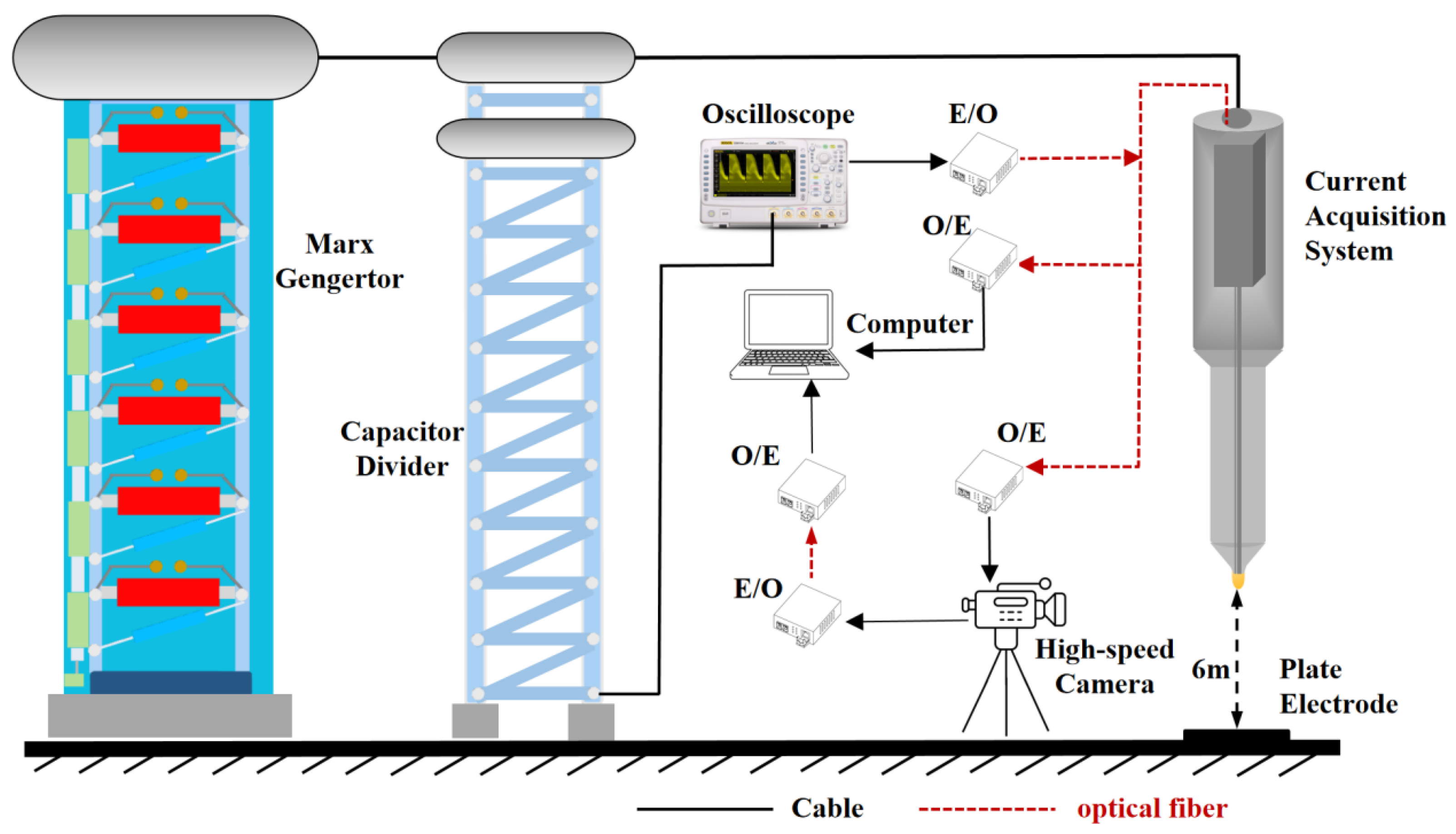
Figure 2.
Typical experimental results when gap withstood. (a) Waveforms of applied voltage and discharge current; (b) Optical Morphology during the Leader Development.
Figure 2.
Typical experimental results when gap withstood. (a) Waveforms of applied voltage and discharge current; (b) Optical Morphology during the Leader Development.
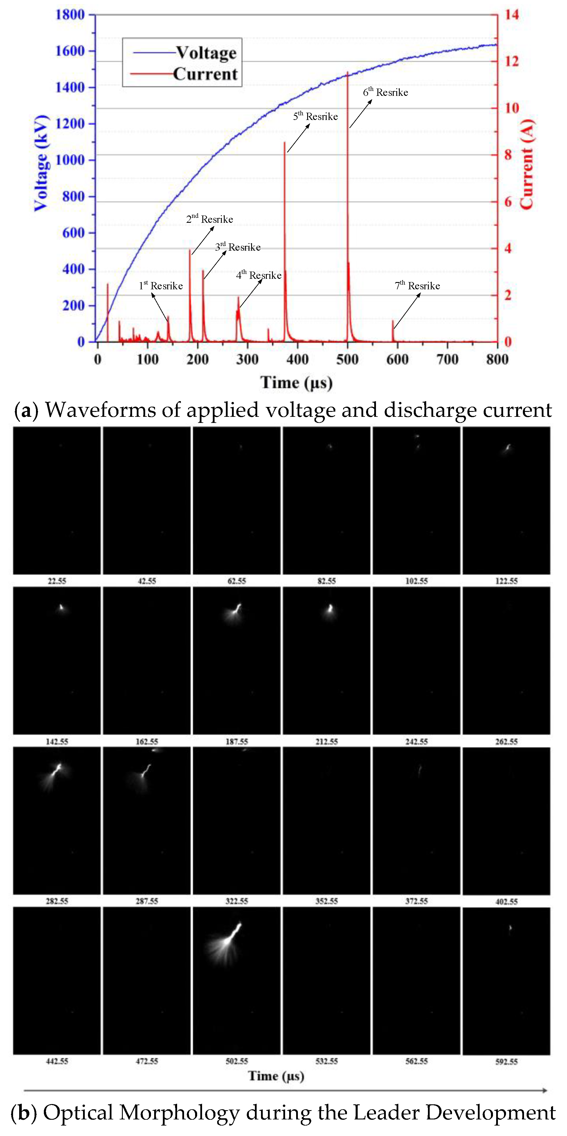
Figure 3.
High-speed photographs and corresponding discharge current before and after the 5th (a) and 6th (b) restrikes when gap withstood.
Figure 3.
High-speed photographs and corresponding discharge current before and after the 5th (a) and 6th (b) restrikes when gap withstood.
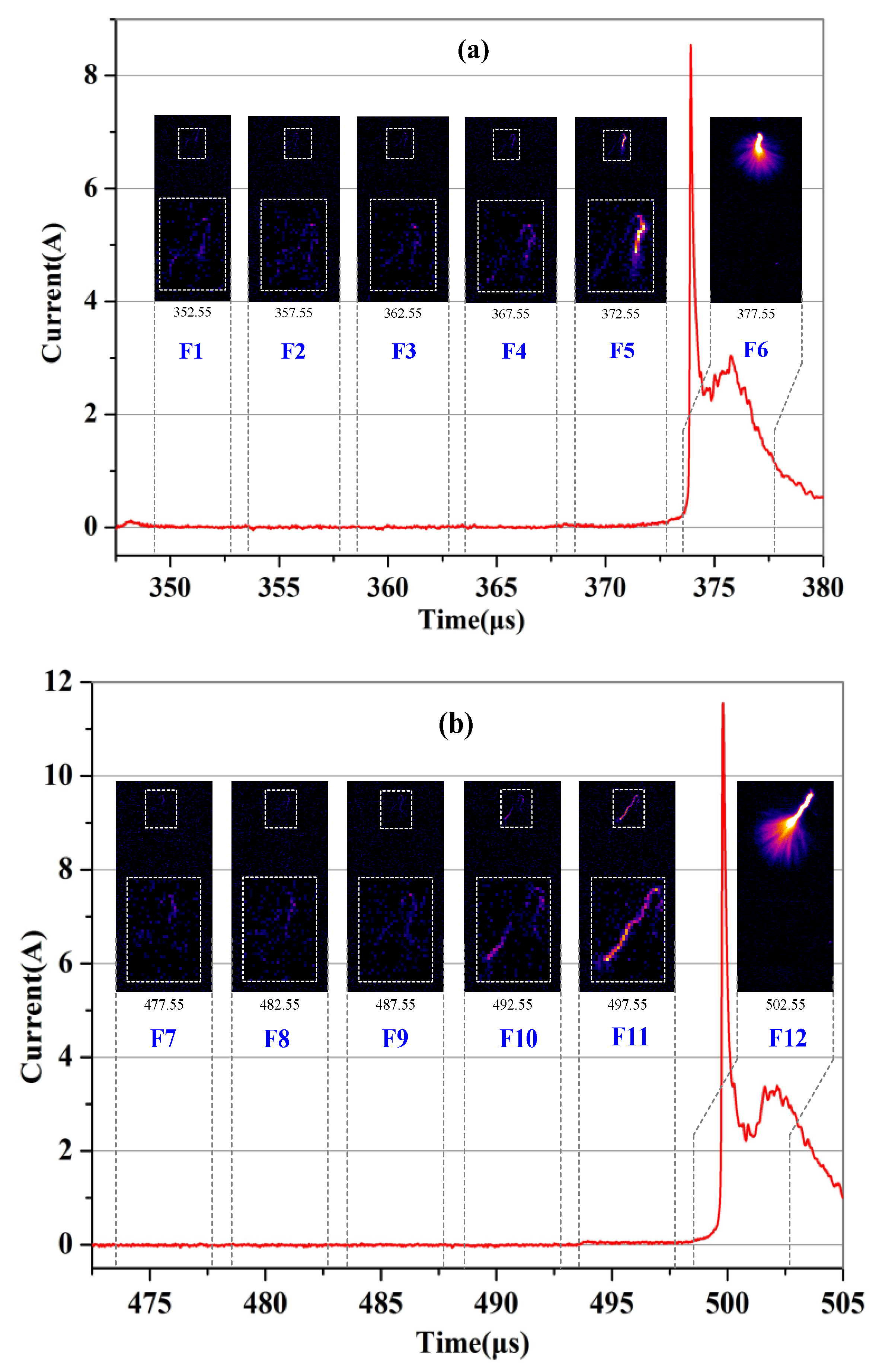
Figure 4.
Typical experimental results when gap broken down. (a) Waveforms of applied voltage and discharge current; (b) Optical Morphology during the Leader Development.
Figure 4.
Typical experimental results when gap broken down. (a) Waveforms of applied voltage and discharge current; (b) Optical Morphology during the Leader Development.
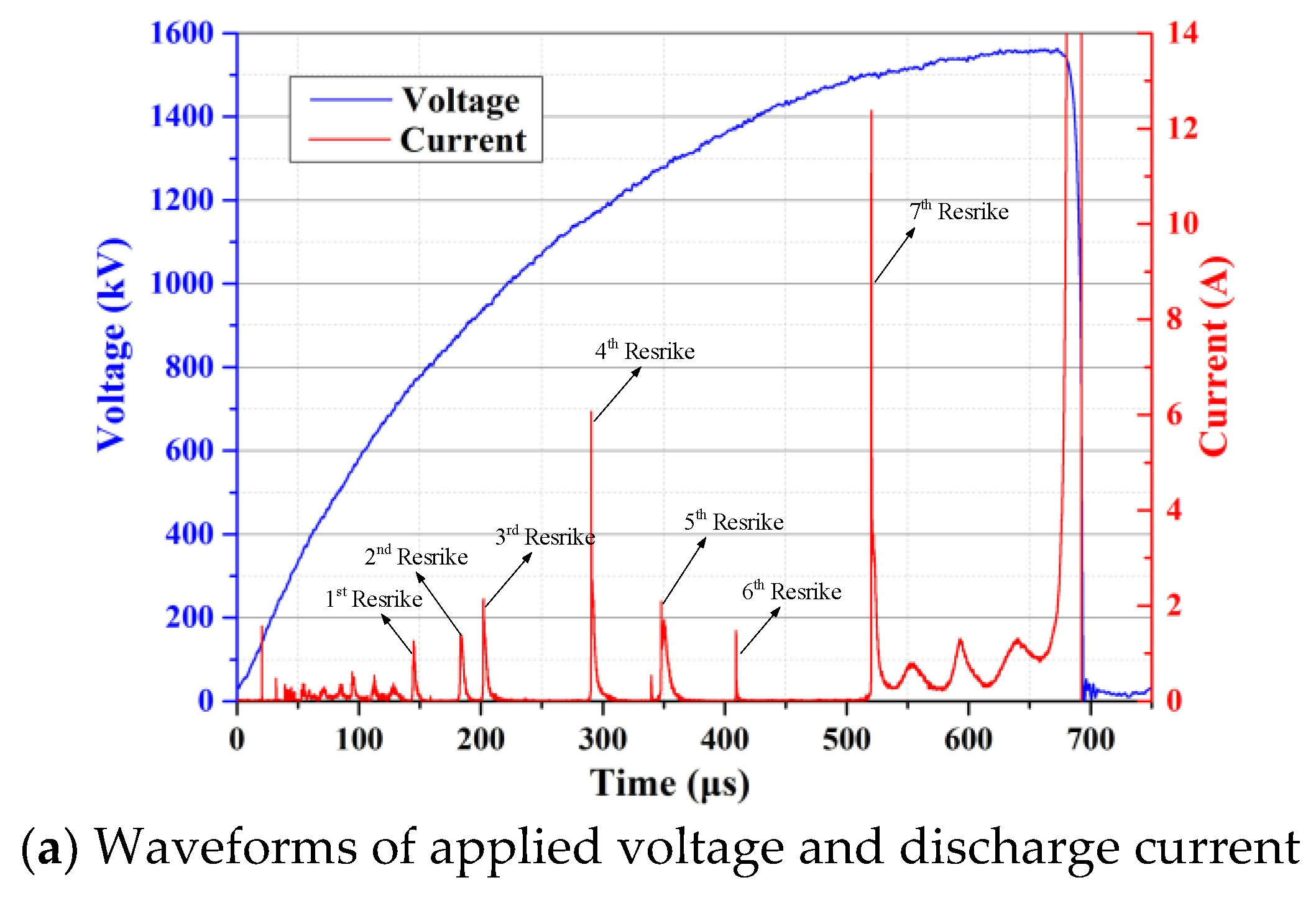
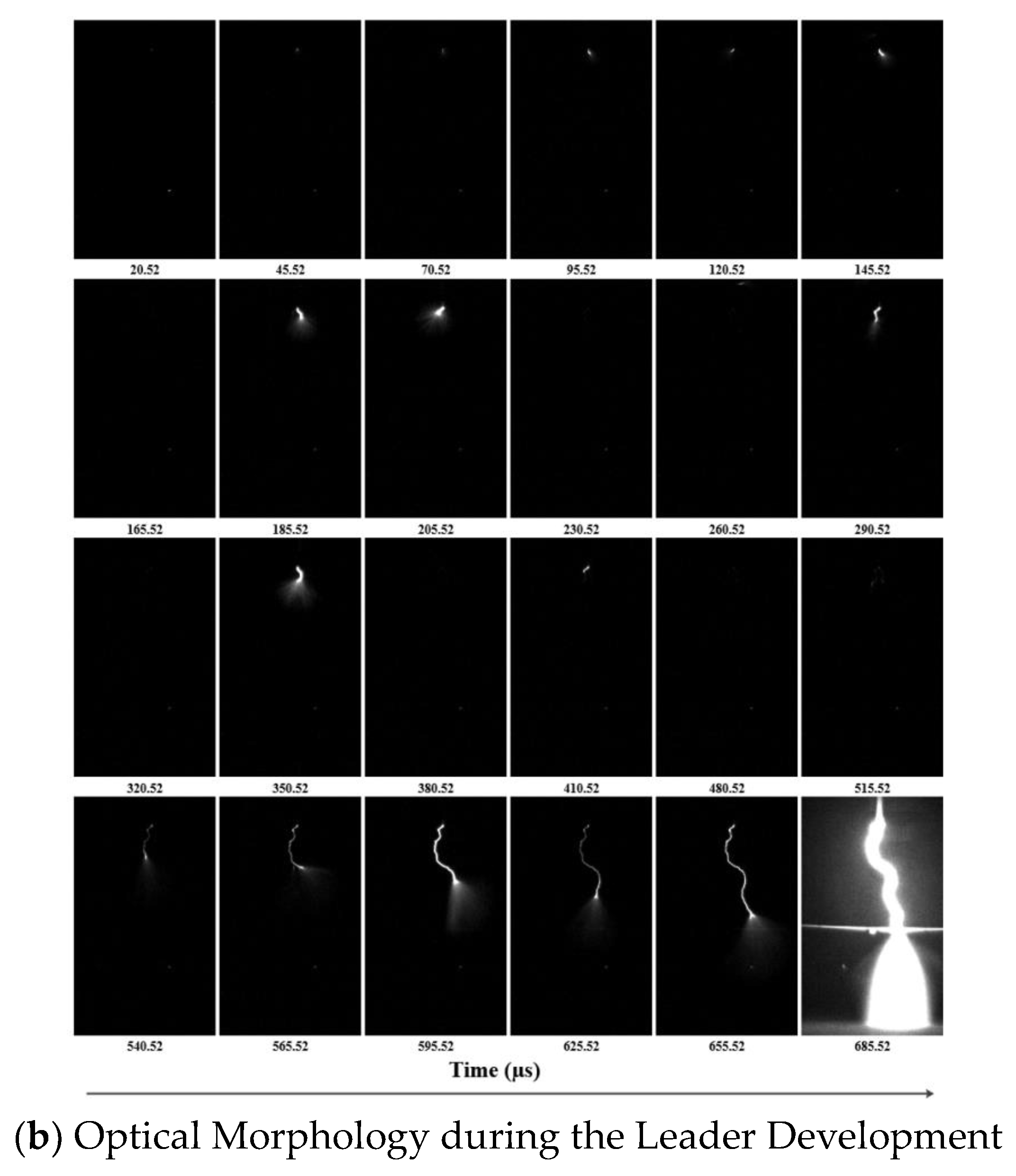
Figure 5.
High-speed photographs and corresponding discharge current before and after the 4th (a) and 7th (b) restrikes when gap broken down.
Figure 5.
High-speed photographs and corresponding discharge current before and after the 4th (a) and 7th (b) restrikes when gap broken down.
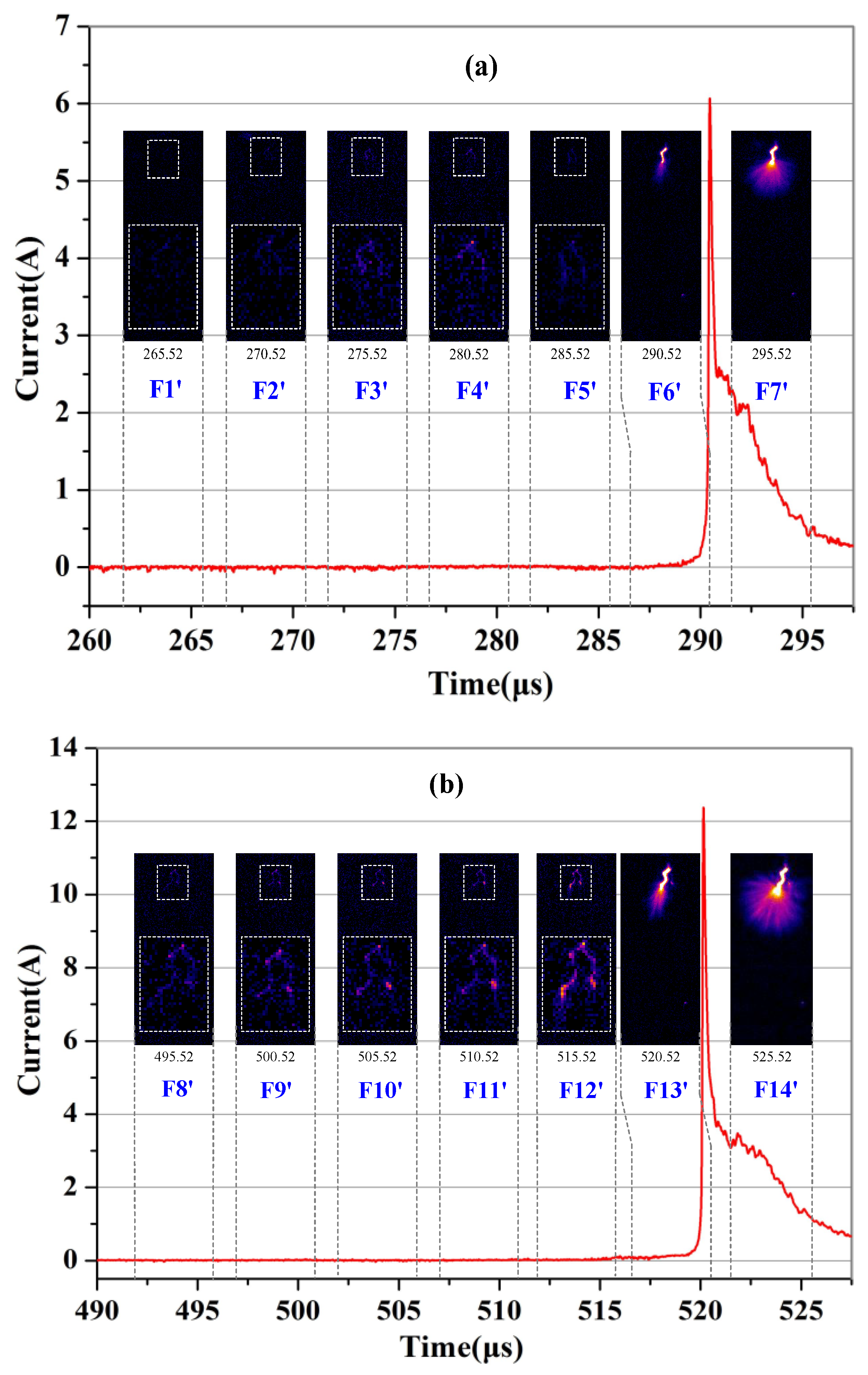
Figure 6.
Relationship between the relaxation time before restrike and the peak value of current at the occurrence of restrike.
Figure 6.
Relationship between the relaxation time before restrike and the peak value of current at the occurrence of restrike.
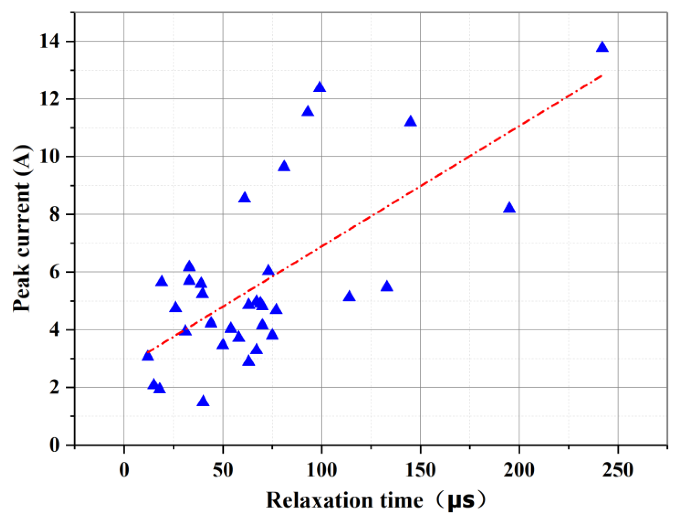
Figure 7.
Schematic diagram of the luminescence of the leader channel during the relaxation process.
Figure 7.
Schematic diagram of the luminescence of the leader channel during the relaxation process.
Disclaimer/Publisher’s Note: The statements, opinions and data contained in all publications are solely those of the individual author(s) and contributor(s) and not of MDPI and/or the editor(s). MDPI and/or the editor(s) disclaim responsibility for any injury to people or property resulting from any ideas, methods, instructions or products referred to in the content. |
© 2025 by the authors. Licensee MDPI, Basel, Switzerland. This article is an open access article distributed under the terms and conditions of the Creative Commons Attribution (CC BY) license (https://creativecommons.org/licenses/by/4.0/).
Copyright: This open access article is published under a Creative Commons CC BY 4.0 license, which permit the free download, distribution, and reuse, provided that the author and preprint are cited in any reuse.


