
Submitted:
11 March 2025
Posted:
12 March 2025
You are already at the latest version
Abstract
Traditional Proportional Integral and Derivative (PID) controllers are often utilised in industrial control applications due to their simplicity and ease of implementation. However, their performance can be limited in complex, nonlinear, time-delayed systems, as well as in noisy feedback loops. This study introduces Groupers and Moray Eels Optimization (GMEO) with Dual-Stream Multi-Dependency Graph neural network (DMGNN) to optimize PID controller parameters addressing main challenges like nonlinearity, dynamic adaptation to changing conditions, and robust performance under variable operating conditions. The proposed system combines the GMEO algorithm to optimize the PID gains and the DMGNN model to predict and locally adjust these parameters, ensuring improved accuracy and responsiveness. By dynamically tuning the PID parameters based on current system conditions, the system adapts to varying input voltages and load changes, optimizing application performance. The proposed strategy is assessed and contrasted with existing strategies on the MATLAB platform. The proposed system achieves a significantly reduced settling time of 100 ms, ensuring rapid response and stability under varying load conditions. Additionally, it minimizes overshoot to 1.5% and reduces the steady-state error to just 0.005V, demonstrating superior accuracy and efficiency compared to existing methods. These improvements demonstrate the system’s ability to deliver optimal performance while effectively adapting to dynamic environments, showcasing its superiority over existing techniques.
Keywords:
buck-boost converters
; proportional integral derivative
; schottky diode
; error signal
; control signal
; steady-state error
; tuning methods
1. Introduction
The simplicity, convenience of use, and typically satisfactory performance of proportional-integral-derivative (PID) controllers make them popular in industrial applications [1]. These controllers are often employed in power electronic systems, such as DC-DC converters and inverters, for voltage, current, and power regulation [2]. In particular, PID controllers are applied in buck-boost converters to maintain stable output voltages despite varying input voltages or load conditions [3]. Buck-boost converters, which can adjust the input voltage according to the switching element's duty cycle, are frequently seen in battery-operated devices, solar arrays, and uninterruptible power supplies. However, the inherent nonlinearities and switching dynamics in buck-boost converters present challenges for traditional PID control, particularly under time-varying or dynamic conditions [4,5]. The traditional PID tuning methods like Ziegler-Nichols and Cohen-Koon, often yield suboptimal results in these nonlinear systems, as they are designed for linear or time-invariant conditions [6]. Consequently, conventional PID controllers, which are typically tuned for steady-state performance [7], may fail to provide adequate transient response or stability in applications where load or input voltage fluctuates [8]. Moreover, in the presence of high-frequency switching noise, which is characteristic of buck-boost converters, improper PID tuning can lead to performance degradation such as overshoot or instability [9]. The control process can become more complicated when the system is subjected to fluctuating load conditions, making it crucial to adjust PID parameters to maintain optimal performance [10]. Recent advancements have focused on adaptive PID control strategies, which dynamically adjust the controller parameters to handle the system’s nonlinearities and improve its robustness [11]. One approach is using optimization techniques like particle swarm optimization or genetic algorithms, which fine-tune PID parameters to achieve better performance in nonlinear and time-varying environments [12]. An additional promising strategy involves incorporating artificial intelligence or machine learning models to dynamically adjust PID gains, enhancing the controller's adaptability [13]. Despite these advancements, traditional PID control still faces limitations in achieving optimal performance under highly dynamic and nonlinear conditions [14].
In buck-boost converters, the PID controller must maintain a delicate balance between stability, transient response, and steady-state accuracy, which is often challenging due to the varying dynamics of the system [15]. A key challenge lies in selecting PID gains that remain effective across a variety of operational circumstances, including different load levels and input voltages [16]. In order to enhance the performance of PID controllers in buck-boost converters, current research is still investigating hybrid and adaptive control techniques [17]. The importance of continuous adjustment and fine-tuning of PID parameters becomes evident as the converter’s dynamic response must be matched with external changes, requiring constant optimization [18]. High-frequency noise from the switching operation of the converter can further complicate the controller’s performance, leading to higher overshoot and instability unless properly addressed [19]. Therefore, more sophisticated approaches that integrate global optimization and adaptive feedback mechanisms are crucial for improving the overall stability and efficiency of PID-controlled buck-boost converters under dynamic conditions [20].
2. Literature Review
In the literature, various research works are available based on PID controller optimization, adaptive control strategies, and performance enhancement in buck-boost converters using different methods and aspects. Few of these works are reviewed as follows.
Sangeetha et al. [21] suggested a hybrid technique for fractional-order proportional integral derivative (FOPID) controller performance analysis of buck converters. Capuchin Search Algorithm (CapSA) and the Golden Jackal Optimisation (GJO) were integrated into this hybrid technique. The Capuchin Search Algorithm was used to improve the Golden Jackal Optimization's update behaviour, resulting in the improved GJO (IGJO) approach. Because power converters were nonlinear, they are difficult to regulate, and there was a constant quest for efficient and effective controllers. Recently, it has been demonstrated that fractional-order controllers are more efficient in power electronic systems. The best design for a fractional-order PID controller for the buck converter was found using the IGJO approach.
Warrier et al. [22] presented a complex-order PI controller for DC–DC buck and boost converter control that combines a complex-order integrator. Four parameters in the intricate PID controller require adjustment. The Metaheuristic Cohort Intelligence method was used to optimize the design of the complex-order PI controller. The outcomes were contrasted with those of a PID controller of fractional order. It was found that the complex PI controller was more resilient to changes in parameters and offered a better response than the FOPID controller.
Nanyan et al. [23] presented an improved Sine Cosine Algorithm (ISCA) for the optimization of a DC-DC buck converter using a PID controller. The restrictions of the conventional Sine Cosine Algorithm (SCA) were addressed through two separate modifications, leading to a synergistic use of nonlinear equations in the instrumental mechanism to revise the average location. The first modification tackled the issue of local optima by introducing an instrumental function to revise the average location. The second change applied a nonlinear equation to the algorithm's reducing position-updating mechanism, coordinating the traditional SCA's disproportional exploration and exploitation phases.
Ghamari et al. [24] designed a Lyapunov-based model reference PID controller for a DC/DC buck converter using their approach. For more dependable functioning, the parameters must be returned, and the PID approach is unsuitable for real-world applications due to a variety of disruptions. To solve this, the PID approach used an adaptive mechanism based on the Lyapunov definition, which improved the system's stability and resilience to a range of shocks. The system was also handled as a "black-box," which removes the requirement for precise mathematical modelling and eases installation and computing load. As a contemporary adaptive algorithm, the Lyapunov notion may provide optimum solutions more quickly while maintaining dependable stability and accuracy.
Garcia-Chavez et al. [25] suggested a reliable technique that makes use of a sliding mode controller and many proportional-integral loops. Experimental validation confirms the resilience and a formal proof of asymptotic stability was given. The study shows that the needed smooth voltage signals may be delivered to the motor by properly managing the power electronic converter.
Omer et al. [26] suggested a DC-DC boost converter and a PV module with an adjustable Machine Learning Gradient Boosting (MLGB) controller. By capturing input/output signals and emulating a PI controller, the raw dataset was produced. Each feature's dynamic behaviour, inter-feature dependability, and relevance to the model output were explained by data pre-processing that included feature engineering and Shapley Additive Explanations (SHAP) values. The Cat Boost technique was used to create the model, and cross-validation was used to adjust the hyperparameters.
AAltbawi et al. [27] have investigated the use of the Fractional-Order Proportional Integral Derivative (FOPID) controller in the Automatic Voltage Regulator (AVR) optimum design, considering its better control qualities and more adjustable tuning options in comparison to the traditional PID regulator. Since the FOPID has two additional tuning parameters (µ and ʎ) compared to the conventional PID, its tuning process is more complex. A self-regulated off-line optimal tuning method based on the Gradient-Based Optimization (GBO) algorithm was adopted in the study. The chosen Fitness Function (FF), which was chosen as the Integral Time Absolute Error (ITAE) in this research, was minimised to produce the best FOPID benefits. Table 1 displays the Summary of research work.
The generic review of recent research highlights various optimization techniques designed to enhance the control systems' performance, particularly in Buck-Boost converters, by optimizing PID controllers for better stability, efficiency, and dynamic adaptation under varying load conditions. The existing techniques include Improved Golden Jackal Optimization (IGJO) optimized PID, Improved Sine Cosine Algorithm (ISCA) optimized PID, Cohort Intelligence Algorithm (CTA) optimized PID, and Lyapunov-based adaptive PID (L-based adaptive PID). The IGJO Optimized PID suffers from slow convergence, high overshoot, higher steady-state error, and sensitivity to initial conditions, making it less suitable for precision-critical applications. It also struggles to maintain stability in systems with significant variations in load or input, reducing its reliability in dynamic environments. The ISCA Optimized PID faces challenges with response speed and precision, and its optimization process can be computationally expensive, limiting scalability for larger or more complex systems. Additionally, it may not handle nonlinearities effectively. The CTA Optimized PID has limited adaptation to highly dynamic conditions, resulting in slower adjustments in unpredictable systems, and reduced robustness under external disturbances, leading to performance degradation. The L-based Adaptive PID relies on Lyapunov functions, limiting its application to specific system types. It also exhibits slower adaptation in dynamic environments, higher computational complexity, and reduced effectiveness in nonlinear systems, making it less practical for fast-changing or highly nonlinear applications. Very few approach-based studies are offered in the literature to deal with this problem; these issues and disadvantages served as the impetus for this study work.
The proposed GMEO-DMGNN method was chosen due to its unique ability to address the complex optimization challenges in PID controllers for buck-boost converters. This combination overcomes existing drawbacks by offering better adaptability, faster convergence, and enhanced stability compared to conventional methods. Advantages include improved stability, reduced overshoot, minimized steady-state error, and faster settling times under varying loads. The novelty lies in integrating the GMEO with the DMGNN model for fine-tuning PID parameters, ensuring superior performance. The method works by leveraging GMEO for global search and DMGNN for localized fine-tuning of PID parameters, enhancing efficiency in dynamic systems. Compared to existing techniques, the GMEO-DMGNN method ensures better adaptability, responsiveness, and optimal performance in buck-boost converters under changing conditions, making it a more robust and efficient solution.
The following are the paper's primary contributions:
- The system combines GMEO's global optimization with DMGNN's local fine-tuning to dynamically adjust PID parameters based on system conditions, ensuring rapid adaptation to varying input voltages and load changes.
- The approach effectively handles nonlinearity and noise in feedback loops, offering robust performance in complex and nonlinear systems, which enhances the stability and efficiency of the converter.
- The method enhances system adaptability, allowing the PID controller to function optimally across a wide range of operating conditions, improving long-term system reliability.
- By integrating GMEO and DMGNN, the system significantly reduces settling time to 100 ms, ensuring faster system response and improved performance under dynamic operational conditions.
The rest of the document is arranged as follows: Part 2 clarifies the configuration for Optimizing PID Controllers in Buck-Boost Converters. Part 3 discusses the hardware description. Part 4 discusses the proposed GMEO-DMGNN. The results and discussion are clarified in Part 5, and Part 6 contains the conclusions.
3. Configuration for Optimizing PID Controllers in Buck-Boost Converters
Figure 1 illustrates the block diagram for optimizing PID controllers in buck-boost converters. It shows that the reference voltage is compared with the output voltage through a feedback loop to regulate the system. Subtracting from Vref creates the error signal, which is then sent to the PID controller. Based on the error signal, the PID controller modifies the control signal u(t), which is then utilised to regulate the buck-boost converter's output voltage Vout. The proposed GMEO-DMGNN method is integrated with the PID controller to enhance its performance by optimizing the PID parameters. The error signal and the control signal are dynamically adjusted through the GMEO-DMGNN method, which fine-tunes the PID parameters for optimal performance under varying load conditions. The integration of GMEO-DMGNN helps improve the system’s stability and efficiency, ensuring that the output voltage is maintained at the desired set point while adapting to dynamic changes. The GMEO-DMGNN method, works by continually fine-tuning the PID parameters, allowing the system to adapt to these changing conditions. As a result, the system is able to maintain a steady output voltage (Vout) that is as close as possible to the reference voltage (Vref), while also improving the overall stability, efficiency, and performance of the converter. Through this method, the proposed system not only ensures precise voltage regulation but also reduces overshoot, improves settling time, and enhances system robustness under various operating scenarios.
3.1. Modelling of Buck-Boost Converter
A buck-boost converter is a type of DC-DC converter that integrates the fundamental principles of both bucks and boost converters in one circuit [28]. This converter may produce either a higher or lower output voltage than the input voltage.
Assuming the converter operates in boost mode with ideal efficiency, the best value for the load resistor can be determined using the energy balance principle.
The boost converter's voltage gain equation while it operates in continuous conduction mode (CCM) may be used to determine the duty cycle, while the energy balance concept is used to calculate the load resistor.
where the input voltage is given, the duty cycle is then calculated. Once the duty cycle has been established, the inductor is made to restrict the input current ripple .
where the current ripple and the switching frequency are established, the input inductor's inductance is then calculated. The following formula may be used to determine the input capacitor, :
With is the minimum output voltage.The output capacitor is given in eqn (5)
With is the maximum output voltage. Figure 2 This ensures a comprehensive and accurate representation of the converter's performance under varying load conditions.
3.2. Modelling of PID Controller
A feedback control loop is used by a PID controller to make clear linkages between the system variables, minimise the impact of disturbances, and guide the system towards the desired state [29]. The error at time , represented by , is sent into the controller. The discrepancy between the measured and reference values is known as this error. The action applied to the system or plant is represented by the PID controller's output, . The integral gain multiplied by the error's integral, the proportional gain multiplied by the error magnitude, and the derivative gain multiplied by the error's derivative are the three terms that make up the control signal, or actuation. Some of these terms may be set to zero.
The control signal , which is the total of the P, I, and D terms, is returned by the PID controller. Figure 3 In this case, for proportional gain, stands for derivative gain and for integral gain.
4. Hardware Description
Buck-boost converter is developed with suitable properties before incorporating optimization techniques into a PID controller. The converter can handle the desired input and output voltages, loads and switching frequencies, certain characteristics and factor values are given in Table 2. An essential part of a buck-boost converter, the inductor (L)is responsible for both storing and transferring energy.
The value of the inductor has significant effects on the converter's performance and efficiency. The inductor's value has a major impact on the converter's performance and efficiency.The eqn 7 is used to get the inductance value.
Here, indicates the highest output current that can pass through the inductor, usually set between 20% and 40% of the total allowable ripple current. Assuming (for 40% ripple) will be given by eqn 8.
The selected value of is 150 µH. An output capacitor is required to lessen voltage ripple at the buck-boost converter's output. This helps stabilise the output by reducing voltage swings and removing high-frequency switching noise. Using the eqn 10, the capacitance value is determined based on the permitted ripple voltage, switching frequency and inductor ripple current.
The output voltage remains stable with the correct capacitance, ensuring reliable converter performance. In a low-side switching setup, a MOSFET (e.g., IRF540N, 100V, 33A) handles the maximum input voltage and current. A Schottky diode (1N5822) is selected for its fast recovery time and high current handling with minimal forward voltage drop. The LM5118 IC controls Pulse Width Modulation (PWM) switching and feedback. Resistors set the output and reference voltages and feed back to the control loop. After initial tuning via simulation or testing, optimization techniques and ML models adjust the PID constants to enhance efficiency.
The parameters for, and should be found using Ziegler-Nichols technique and then refined by simulation to finalize the PID design. Furthermore, machine learning techniques are used to dynamically alter these parameters to guarantee ideal performance under various operating circumstances.To maintain the output voltage with as few errors as possible, the ML-enhanced PID controller adjusts the gain depending on data, such as changes in input voltage or load.
5. ProposedGMEO-DMGNN Method for Enhancing PID Control in Buck-Boost Converters
This section outlines the integration of a Dual-Stream Multi-Dependency Graph Neural Network (DMGNN) with the Groupers and Moray Eels (GMEO) for optimizing PID controller parameters. GMEO is used to optimize PID gains (Ki, Kp, Kd), while the Dual-Stream Multi-Dependency Graph Neural Network (DMGNN) predicts and locally adjusts these parameters to enhance performance. GMEO explores large solution spaces, maintains diversity to avoid local optima, and handles nonlinear systems to improve PID controller performance by enhancing stability, reducing overshoot, and optimizing response time. DMGNN further refines optimization by capturing complex dependencies and learning both global and local patterns, which accelerates convergence and improves performance in dynamic systems like buck-boost converters. The combination of GMEO's global search with DMGNN’s local adjustments optimizes PID parameters more efficiently, improving system stability, response time, and adaptability while ensuring faster convergence in complex, dynamic systems.
5.1. Optimization Using Groupers and Moray Eels (GMEO)
In this section, the GMEO is described [30] and utilized to optimize the controller parameters of PID gains, such as Kp, Ki, and Kd. The GMEO algorithm offers a robust global search mechanism, efficiently optimizing PID parameters to enhance performance in nonlinear, dynamic systems, ensuring improved stability, faster response, and better adaptability in buck-boost converters.It improves the PID controller’s ability to adapt to varying system conditions, reducing overshoot, settling time, and steady-state error, while enhancing overall system stability and performance in buck-boost converters.GMEO was chosen for its ability to effectively handle the complexities of nonlinear, dynamic systems by offering a balanced global search approach, optimizing PID parameters for improved control and performance in buck-boost converters.
Step 1: Initialization
Set the input variables to first values. In this instance, the input variables are the PID parameters, which arerepresented as , and .
Step 2: Random Generation
In matrix form, the input variables were generated at random.
where, indicates the random generation and indicates the system parameters, indicates the count of decision variables.
Step 3: Fitness Function
The fitness was evaluated which was described by,
where, refers Integral of Time-Weighted Absolute Error (ITAE), specifies the time variable and specifies the error signal at time .
Step 4: Primary Search (PS) Phase
GMEO agents explore the search space for optimal PID controller parameters (Kp, Ki, Kd), mimicking the zigzag swimming pattern of groupers hunting prey. This random exploration ensures thorough coverage of the solution space, aiming to find the optimal controller gains that minimize performance errors like transient response, steady-state error, and overshoot.
Here, specifies the first location of search agent of dimension, are the search space's upper and lower bounds, specifies the overall count of dimensions, specifies the number of search agents, and specifies a random vector that follows a uniform distribution, with values ranging from 0 to 1.
Step 5: PairAssociation (PA) Phase
In this phase, the best-performing agents (groupers) collaborate with other high-quality agents (moray eels) to improve search efficiency. This cooperative interaction enhances the exploration of promising regions in the solution space. By leveraging the strengths of both agents, the search process becomes more targeted, accelerating convergence toward the optimal PID parameters. The agents dynamically adjust their positions based on the most promising solutions, ensuring a balance between global exploration and local refinement for improved accuracy in optimizing the PID controller.
Step 6: Encirclingor Extended Search (ES) Phase
Agents refine their search by adaptively adjusting their positions toward promising regions. This phase enhances local exploration, allowing agents to dynamically focus on areas with higher potential for optimal PID parameters. The cooperative movement mimics the coordinated behavior of groupers and moray eels, ensuring a balance between exploitation and exploration. This adaptive search approach improves the likelihood of finding the global optimum and helps avoid premature convergence.
where, the coordinates of the prey in each dimension, specifies the location of a grouper; is the location of an eel, is the separation between the prey and the grouper, and is the distance between the grouper and the eel.
Step 7: Attackingand Catching Phase
Agents converge on the best solution by intensifying the search around the optimal PID gains. This phase improves convergence accuracy by gradually reducing the search radius, ensuring precise identification of the optimal controller parameters. The shrinking mechanism enables a finer search around the most promising solution, refining the PID gains for better system performance. This stage also helps to reduce the steady-state error and enhances system stability by continuously updating the solution based on the best-performing agents.
where and is a shrinking ratio and refers the radius.
Step 8: Termination Criteria
The procedure ends if the answer is ideal; if not, it goes back to step 3 for fitness assessments and keeps processing the next steps until the best answer is discovered. Thus, GMEO effectively optimized the controller parameters of PID gains. The flowchart of GMEO is shown in Figure 4.
5.2. Dual-Stream Multi-Dependency Graph Neural Network (DMGNN)
In this section, the prediction using Dual-Stream Multi-Dependency Graph Neural Network (DMGNN) is discussed [31]. DMGNN enhances optimization by efficiently predicting and adjusting PID parameters, capturing complex dependencies in dynamic systems. It was chosen for its ability to model both global and local patterns through its dual-stream architecture, making it well-suited for optimizing PID parameters in nonlinear and time-sensitive systems like buck-boost converters. This capability ensures faster convergence and significantly improves performance.
where, the trainable weight matrix for feature transformation specified by and . DMGNN captures the complex dependencies and relationships between the PID parameters and the system's dynamic behavior. Its dual-stream architecture learns both global patterns (long-range dependencies) and local patterns (short-range dependencies) between the system states, improving PID parameter adjustment.
Here, the learnable transformation matrix and bias is specified by and , correspondingly, while indicates the function. The DMGNN refines the parameters Kp, Ki, and Kd by adjusting them locally, ensuring that the PID controller performs optimally under different load conditions and varying operational environments.
where, a pre-defined hyper-parameter and reduce to as the training proceeds is specified by , is the pre-defined hyper parameter, the features from the two branches is specified by and , and the concatenation operation is specified by . The adjusted PID parameters are used to control the buck-boost converter, ensuring that the system’s output voltage is maintained at the desired set point while adapting dynamically to load variations.
where and variables related to the system's performance and state respectively while represents the computation process of hazard rates. DMGNNdynamically adjusts the ideal PID parameters Kp, Ki, and Kd based on system conditions by learning both global and local patterns in the system’s behavior.
6. Result and Discussion
The proposed method's performance is demonstrated in this section using the results of the simulation. The GMEO-DMGNN approach for buck-boost converter PID controller optimisation was proposed in this study. Using the MATLAB environment, the proposed method is assessed and contrasted with other current methods. The proposed method's simulation is shown below.
Figure 5 depicts the voltage response over time using the IGJO optimized PID controller The voltage reaches a peak of approximately 13.6V, overshooting the setpoint by around 1.4V. It then takes about 1000 ms to settle within a 0.2V band around the setpoint. The larger overshoot and prolonged oscillations highlight a key drawback, leading to a less stable and slower response. Figure 6 depicts the voltage response over time using the ISCA optimized PID controller. The voltage rapidly increases, reaching a peak of approximately 13.2V within the first second, with an overshoot of 1.2V. The system then settles in about 500 ms, although the settling time is relatively high, the overshoot of 1.2V suggests that further optimization could improve system stability and reduce peak voltage. Figure 7 depicts the voltage response over time using the CTA optimized PID controller. The initial voltage rise shows a peak of 13.6V, with a substantial overshoot of 1.6V above the set point. After the peak, the voltage begins to oscillate but stabilizes within approximately 200ms. However, the significant overshoot and the time taken to stabilize highlight a drawback of the CTA optimized PID system, as it results in slower settling and takes longer to reach steady-state performance.
Figure 8 illustrates the voltage response over time using the L-Based Adaptive PID. Initially, the voltage rises quickly, peaking at around 13.3V, with an overshoot of 1.3V above the set point. After the peak, the voltage starts to oscillate, but these oscillations dampen over a period of about 150ms, allowing the system to settle around the set point, with the persistence of oscillations leading to a slower stabilization process that takes several seconds to fully settle.
Figure 9 depicts the performance comparison of different control strategies. It compares the performance of various PID control strategies, including IGJO Optimized PID, ISCA Optimized PID, CTA Optimized PID, L-Based Adaptive PID, and the proposed GMEO-DMGNN method. Each strategy shows an initial overshoot followed by oscillations before stabilizing. The IGJO Optimized PID controller reaches a peak of approximately 13.6V, overshooting the set point by around 1.4V and takes about 1000 ms to settle within a 0.2V band around the set point. ISCA Optimized PID reaches a peak of 13.2V, with a similar overshoot of 1.2V, and settles in about 500 ms seconds. CTA Optimized PID shows a peak of 13.6V, with a substantial overshoot of 1.6V, and takes approximately 200 ms to stabilize. L-Based Adaptive PID peaks at around 13.3V with an overshoot of 1.3V, settling in about 150ms. The proposed GMEO-DMGNN method shows a peak of 12.9V, with a more controlled overshoot of 1.1V, and settles within approximately 100 ms, demonstrating faster convergence and less oscillation. Therefore, the GMEO-DMGNN method outperforms the other techniques, providing a more stable, faster, and more efficient response for controlling buck-boost converters.
The Table 3 compares the performance of various PID optimization methods based on settling time, overshoot, and steady-state error. The IGJO Optimized PID method has the longest settling time at 1000 ms, with a significant overshoot of 25% and a steady-state error of 0.15V, indicating slower stabilization and moderate accuracy. With a settling time of 500 ms, a 15% decrease in overshoot, and a lower steady-state error of 0.05V, the ISCA Optimised PID approach performs better in terms of stability and accuracy. The CTA Optimized PID method performs even better, with a settling time of 200 ms, a further reduced overshoot of 5%, and a steady-state error of 0.02V, showing faster convergence and enhanced precision. The L-Based Adaptive PID method offers the fastest settling time at 150 ms, with a minimal overshoot of 3% and an almost negligible steady-state error of 0.01V, making it highly stable and precise. Finally, the GMEO-DMGNN (Proposed) method outperforms all others with the fastest settling time of 100 ms, the smallest overshoot of 1.5%, and the lowest steady-state error of 0.005V, providing superior performance in terms of speed, accuracy, and stability. Therefore, the GMEO-DMGNN method stands out as the most efficient and reliable optimization technique for PID controllers. Table 4 presents a comparison of statistical values between the proposed and existing methods. The proposed method achieves the highest mean value of 4.9876x10⁻⁷and the highest standard deviation (SD) of 6.9452 x10⁻¹², surpassing the performance of the existing systems. This indicates that the proposed method offers superior variability and greater adaptability in comparison.
Table 5 compares the Comparison of ITAE, ISE. The proposed system achieves an ITAE of 2.09998998 x10⁻¹³, an ISE of 1.19052756 x10⁻⁶. In comparison, existing methods show higher ITAE and ISE values, with the IGJO Optimized PID achieving an ITAE of 2.39850000 x10⁻¹³and an ISE of 2.73120000 x10⁻⁶, the ISCA Optimized PID yielding an ITAE of 2.36580000 x10⁻¹³and an ISE of 2.62490000 x10⁻⁶, the CTA Optimized PID showing an ITAE of 2.96550000 x10⁻¹³and an ISE of 3.52110000 x10⁻⁶, and the L-based Adaptive PID resulting in an ITAE of 2.9 x10⁻¹³and an ISE of 2.43120000 x10⁻⁶. These results highlight the enhanced accuracy and prediction capability of the GMEO-DMGNN method compared to other systems.
Comparison of efficiency between the proposed and existing methods is displayed in Table 6. The proposed method achieves the highest efficiency at 98.5%, showcasing its ability to deliver optimal solutions quickly and effectively. The IGJO Optimized PID method follows with an efficiency of 82%, indicating slightly lower effectiveness. The ISCA Optimized PID method achieves an efficiency of 89%, while the CTA Optimized PID method has an efficiency of 89.6%. The L-Based Adaptive PID reaches an efficiency of 91%. Overall, the proposed method stands out for its superior efficiency, making it the most effective solution for optimal performance.
The Table 7 compares the optimal PID controller parameters Kp, Ki, Kd for different methods. The proposed GMEO-DMGNN method has the highest Kp at 8.52, Ki at 34.01, and a relatively higher Kdat0.33, making it more responsive and adaptive compared to existing methods. In comparison, other methods like IGJO, ISCA, CTA, and L-based Adaptive PID have lower PID values, making them less efficient in handling dynamic load conditions. The GMEO-DMGNN method stands out for its superior performance and adaptability in optimizing buck-boost converter operation.
6.1. Discussion
The GMEO-DMGNN approach focuses on optimizing PID controller parameters in buck-boost converters, enhancing their performance under dynamic load conditions. By combining the global optimization capabilities of GMEO with the localized adjustment strengths of DMGNN, the approach effectively fine-tunes PID controller parameters for improved performance in buck-boost converters. The integration of both methods ensures more accurate optimization of PID parameters, enhancing system stability, responsiveness, and overall performance under dynamic conditions.This combined framework offers a more robust and efficient solution for optimizing PID parameters, resulting in improved adaptability, faster convergence, and better control performance in buck-boost converters.The proposed method consistently outperformed existing PID optimization techniques, achieving the fastest settling time of 100 ms, the lowest overshoot of 1.5%, minimal steady-state error of 0.005 V, and the highest efficiency at 98.5%. It also demonstrated superior statistical values with a mean of 4.9876x10⁻⁷and a standard deviation of6.9452 x10-12, along with the lowest error integrals, including an ITAE of 2.09998998 x10⁻¹³and an ISE of 1.19052756 x10⁻⁶. This result demonstrates that the proposed GMEO-DMGNN system provides superior performance, exhibiting enhanced speed, accuracy, stability, and efficiency compared to existing PID optimization techniques. This finding indicates the GMEO-DMGNN method's comprehensive superiority in PID optimization, achieved through a combination of optimized performance metrics and enhanced hardware utilization, specifically the highest capacitance.
7. Conclusions
The proposed GMEO-DMGNN approach has been introduced to address the limitations of traditional PID controllers in buck-boost converters. In this study, the GMEO-DMGNN combines the global search capabilities of GMEO with the local adjustment strengths of DMGNN to optimize PID controller parameters. Additionally, this method is highly adaptable to dynamic load conditions, maintaining consistent performance across varying operational environments. Unlike conventional methods that may struggle with nonlinearities or varying conditions, the GMEO-DMGNN approach provides enhanced robustness and adaptability. The proposed method demonstrates superior performance, achieving a settling time of 100 ms, 1.5% overshoot, and a steady-state error of 0.005 V. This approach outperforms existing methods by offering better adaptability, stability, and efficiency in dynamic and nonlinear environments, making it a robust solution for optimizing PID controllers in buck-boost converters. It also achieves a high efficiency of 98.5% ensuring optimal performance while maintaining system stability under varying conditions. The proposed system reduces the ITAE to 2.09998998 x 10⁻¹³ and ISE to 1.19052756 x 10⁻⁶highlights the proposed system's superior efficiency in reducing error and improving control performance. Overall, the proposed GMEO-DMGNN approach significantly improves the performance of PID controllers in buck-boost converters, offering enhanced stability, efficiency, and adaptability under dynamic and nonlinear conditions. Future work could explore the scalability of the approach to different converter topologies, such as multi-phase or bidirectional converters, to enhance its applicability in broader power electronic systems.
References
- Esfandiari, S.; Davari, M.; Gao, W.; Yang, Y.; Al-Haddad, K. A Novel Converter-Based PV Emulator Control Using Lambert W Method and Fractional-Order Fuzzy Proportional-Integral Controller Trained by Harris Hawks Optimization. IEEE Journal of Emerging and Selected Topics in Industrial Electronics 2024. [Google Scholar]
- Mughees, A.; Mughees, N.; Mughees, A.; Mohsin, S.A.; Ejsmont, K. Enhancing stability and position control of a constrained magnetic levitation system through optimal fractional-order PID controller. Alexandria Engineering Journal 2024, 107, 730–746. [Google Scholar]
- Abdolahi, M.; Adabi, J.; Mousavi, S.Y.M. An adaptive extended Kalman filter with passivity-based control for DC-DC converter in DC microgrids supplying constant power loads. IEEE Transactions on Industrial Electronics 2023, 71, 4873–4882. [Google Scholar] [CrossRef]
- Kaplan, O.; Bodur, F.; Ozdemir, M.B. Arbitrary Fixed-Time Sliding Mode Control for Buck Converter with Matched and Mismatched Disturbances Based on Fixed-Time Observer. IEEE Access. 2025. [CrossRef]
- Gangula, S.D.; Nizami, T.K.; Udumula, R.R.; Chakravarty, A. Self-learning Controller Design for DC–DC Power Converters with Enhanced Dynamic Performance. Journal of Control, Automation and Electrical Systems 2024, 35, 532–547. [Google Scholar] [CrossRef]
- Kart, S.; Demir, F.; Kocaarslan, İ.; Genc, N. Increasing PEM fuel cell performance via fuzzy-logic controlled cascaded DC-DC boost converter. International Journal of Hydrogen Energy 2024, 54, 84–95. [Google Scholar] [CrossRef]
- Dey, U.; Veerachary, M. Two-Part Controller Design for Switched-Capacitor Based Buck–Boost Converter. IEEE Transactions on Industrial Electronics. 2024.
- Gaied, H.; Flah, A.; Kraiem, H.; Prokop, L. A comparison between the Quality of Two level and three levels bidirectional Buck-boost converter using the neural network controller. IEEE Access. 2024.
- Lins, A.W.; Krishnakumar, R. Tuning of PID controller for a PV-fed BLDC motor using PSO and TLBO algorithm. Applied Nanoscience 2023, 13, 2911–2934. [Google Scholar]
- LIU, X. Design of CCM boost converter utilizing fractional-order PID and Lyapunov-based PID techniques for PF correction. Electrical Engineering 2024, 1–12. [Google Scholar]
- Acosta-Rodríguez, R.A.; Martinez-Sarmiento, F.H.; Múñoz-Hernandez, G.A.; Portilla-Flores, E.A.; Salcedo-Parra, O.J. Validation of Passivity-Based Control and array PID in High-Power Quadratic Buck Converter through Rapid Prototyping. IEEE Access. 2024.
- Sahin, A.K.; Cavdar, B.; Ayas, M.S. An adaptive fractional controller design for automatic voltage regulator system: Sigmoid-based fractional-order PID controller. Neural Computing and Applications 2024, 36, pp.14409–14431. [Google Scholar]
- Kanungo, A.; Kumar, P.; Gupta, V.; Saxena, N.K. A design an optimized fuzzy adaptive proportional-integral-derivative controller for anti-lock braking systems. Engineering Applications of Artificial Intelligence 2024, 133, 108556. [Google Scholar]
- Yakut, Y.B. A new control algorithm for increasing efficiency of PEM fuel cells–Based boost converter using PI controller with PSO method. International Journal of Hydrogen Energy 2024, 75, 1–11. [Google Scholar]
- Ghamari, S.; Hajihosseini, M.; Habibi, D.; Aziz, A. Design of an Adaptive Robust PI Controller for DC/DC Boost Converter Using Reinforcement-Learning Technique and Snake Optimization Algorithm. IEEE Access. 2024.
- Rajamony, R.; Wang, S.; Ming, W. Modelling and optimal design of a multifunctional single-stage buck-boost differential inverter. IEEE Open Journal of Power Electronics. 2024. [CrossRef]
- Ashok, B.; Michael, P.A. Integration of cascaded controllers for super-lift Luo converter with buck converter in solar photovoltaic and electric vehicle. Analog Integrated Circuits and Signal Processing 2024, 118, 449–466. [Google Scholar]
- Srivastava, A.; Manas, M.; Dubey, R.K. Optimal electrical vehicle-to-grid integration: Three-phase three-level AC/DC converter with model predictive controller based bidirectional power management scheme. Electrical Engineering 2024, 1–23. [Google Scholar] [CrossRef]
- Liu, J.; Wei, T.; Chen, N.; Wu, J.; Xiao, P. Fuzzy logic PID controller with both coefficient and error modifications for digitally-controlled DC–DC switching converters. Journal of Electrical Engineering & Technology 2023, 18, 2859–2870. [Google Scholar]
- Liu, W.; Liu, Y.; Wang, A. Design of CCM boost converter using fractional-order PID and neural-network techniques for power factor correction. Journal of Engineering and Applied Science 2024, 71, 227. [Google Scholar]
- Sangeetha, S.; Revathi, B.S.; Balamurugan, K.; Suresh, G. Performance analysis of buck converter with fractional PID controller using hybrid technique. Robotics and Autonomous Systems 2023, 169, 104515. [Google Scholar]
- Warrier, P.; Shah, P.; Sekhar, R. A Comparative performance evaluation of a complex-order PI controller for DC–DC converters. Results in Control and Optimization 2024, 15, 100414. [Google Scholar]
- Nanyan, N.F.; Ahmad, M.A.; Hekimoğlu, B. Optimal PID controller for the DC-DC Buck converter using the improved sine cosine algorithm. Results in Control and Optimization 2024, 14, 100352. [Google Scholar]
- Ghamari, S.M.; Khavari, F.; Mollaee, H. Lyapunov-based adaptive PID controller design for buck converter. Soft Computing 2023, 27, 5741–5750. [Google Scholar]
- García-Chávez, R.E.; Silva-Ortigoza, R.; Hernández-guzmáN, V.M.; Marciano-Melchor, M.; Orta-Quintana, Á.A.; García-Sánchez, J.R.; Taud, H. A robust sliding mode and PI-based tracking control for the MIMO “DC/DC buck converter–inverter–DC motor” system. IEEE Access 2023, 11, 119396–119408. [Google Scholar]
- Omer, Z.M.; Shareef, H. An adjustable machine learning gradient boosting-based controller for PV applications. Intelligent Systems with Applications 2023, 19, 200261. [Google Scholar]
- Altbawi, S.M.A.; Mokhtar, A.S.B.; Jumani, T.A.; Khan, I.; Hamadneh, N.N.; Khan, A. Optimal design of Fractional order PID controller based Automatic voltage regulator system using gradient-based optimization algorithm. Journal of King Saud University-Engineering Sciences 2024, 36, 32–44. [Google Scholar]
- Chouay, Y.; Ouassaid, M. An Enhanced Buck-Boost Converter for Photovoltaic Diagnosis application: Accurate MPP Tracker and IV Tracer. Scientific African 2025, e02561. [Google Scholar]
- Prag, K.; Woolway, M.; Celik, T. Data-driven model predictive control of DC-to-DC buck-boost converter. IEEE Access 2021, 9, 101902–101915. [Google Scholar]
- Mansour, N.A.; Saraya, M.S.; Saleh, A.I. Groupers and moray eels (GME) optimization: A nature-inspired metaheuristic algorithm for solving complex engineering problems. Neural Computing and Applications 2025, 37, 63–90. [Google Scholar]
- Wang, Z.; Ma, J.; Gao, Q.; Bain, C.; Imoto, S.; Liò, P.; Cai, H.; Chen, H.; Song, J. Dual-stream multi-dependency graph neural network enables precise cancer survival analysis. Medical Image Analysis 2024, 97, 103252. [Google Scholar] [CrossRef] [PubMed]
Figure 1.
Block diagram of optimizing PID controllers in buck-boost converters.
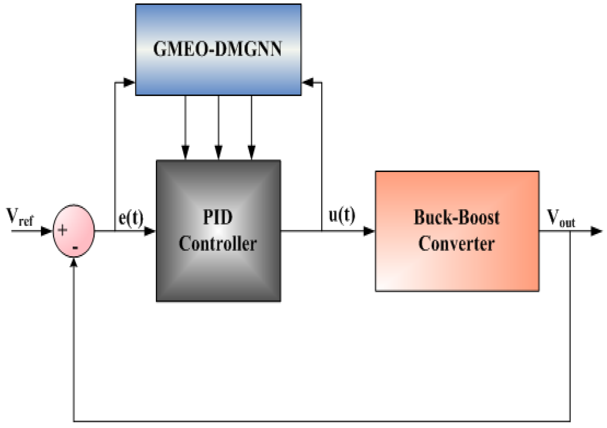
Figure 2.
Buck-Boost Converter.
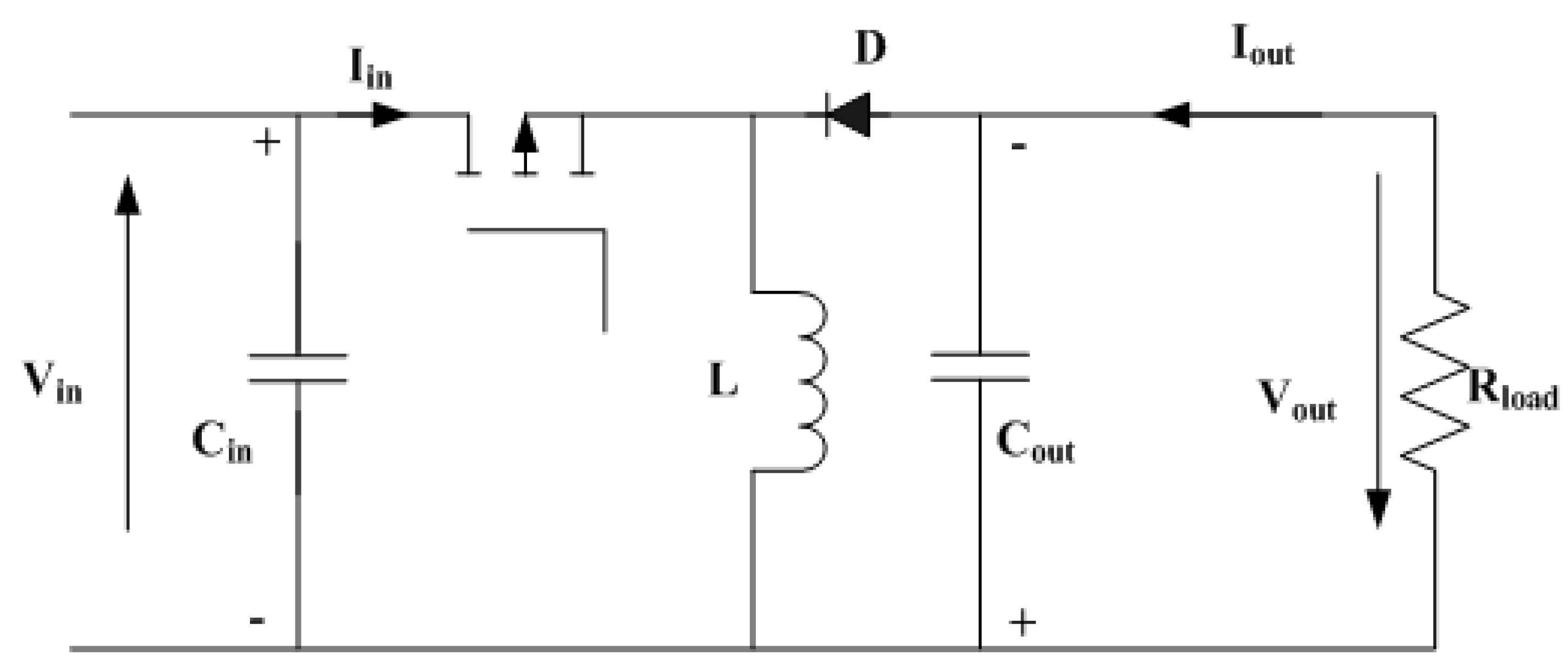
Figure 3.
PID process controller.
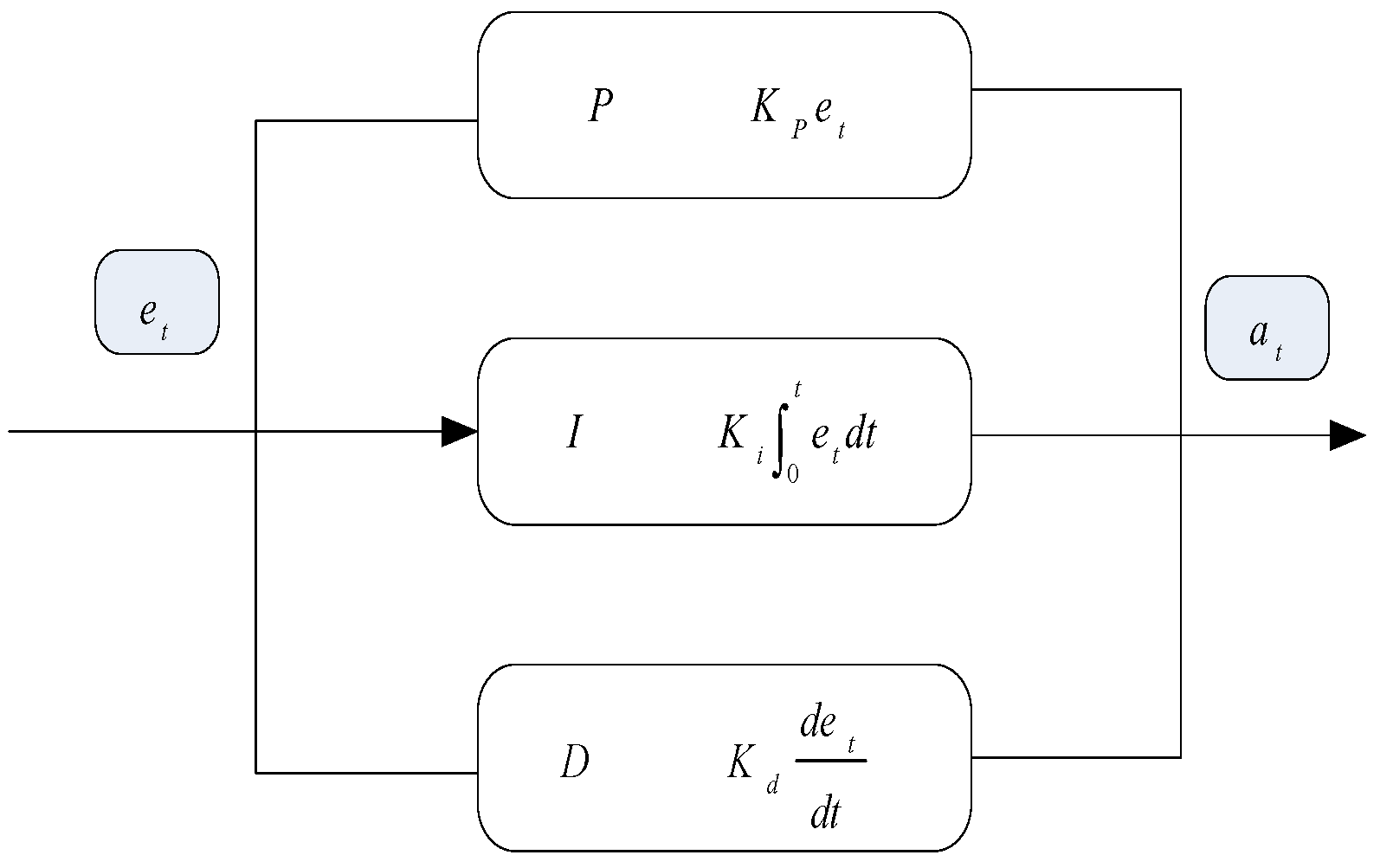
Figure 4.
Flowchart of GMEO.
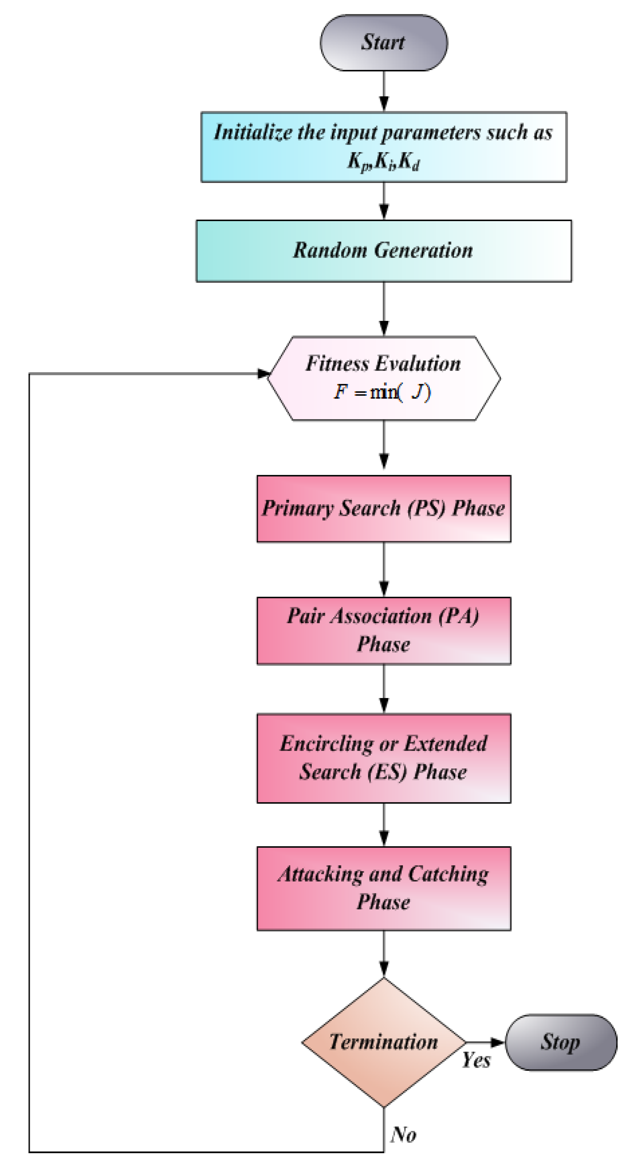
Figure 5.
Performance evaluation of IGJO Optimized PID controller.
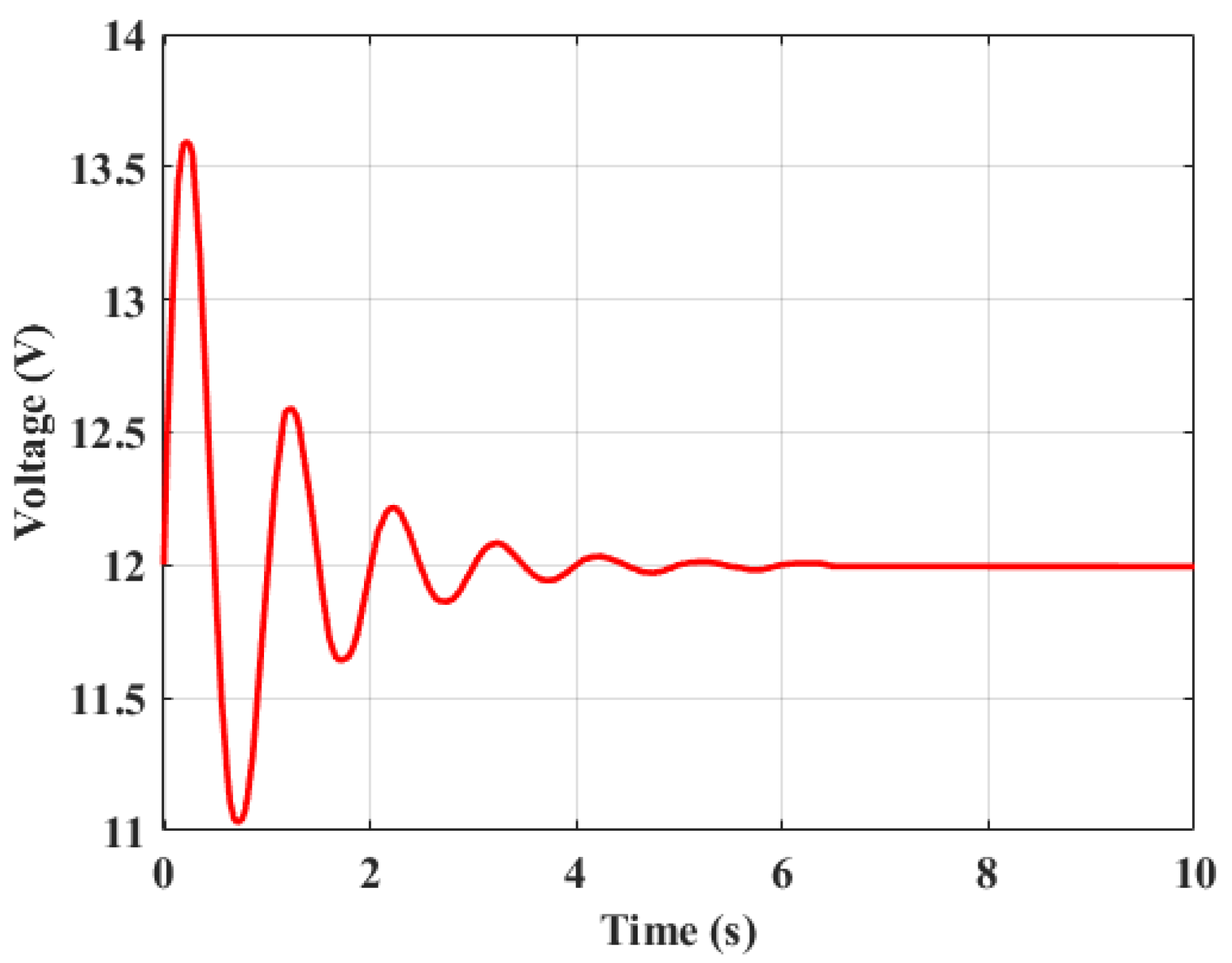
Figure 6.
Performance evaluation ofISCA Optimized PID controller.
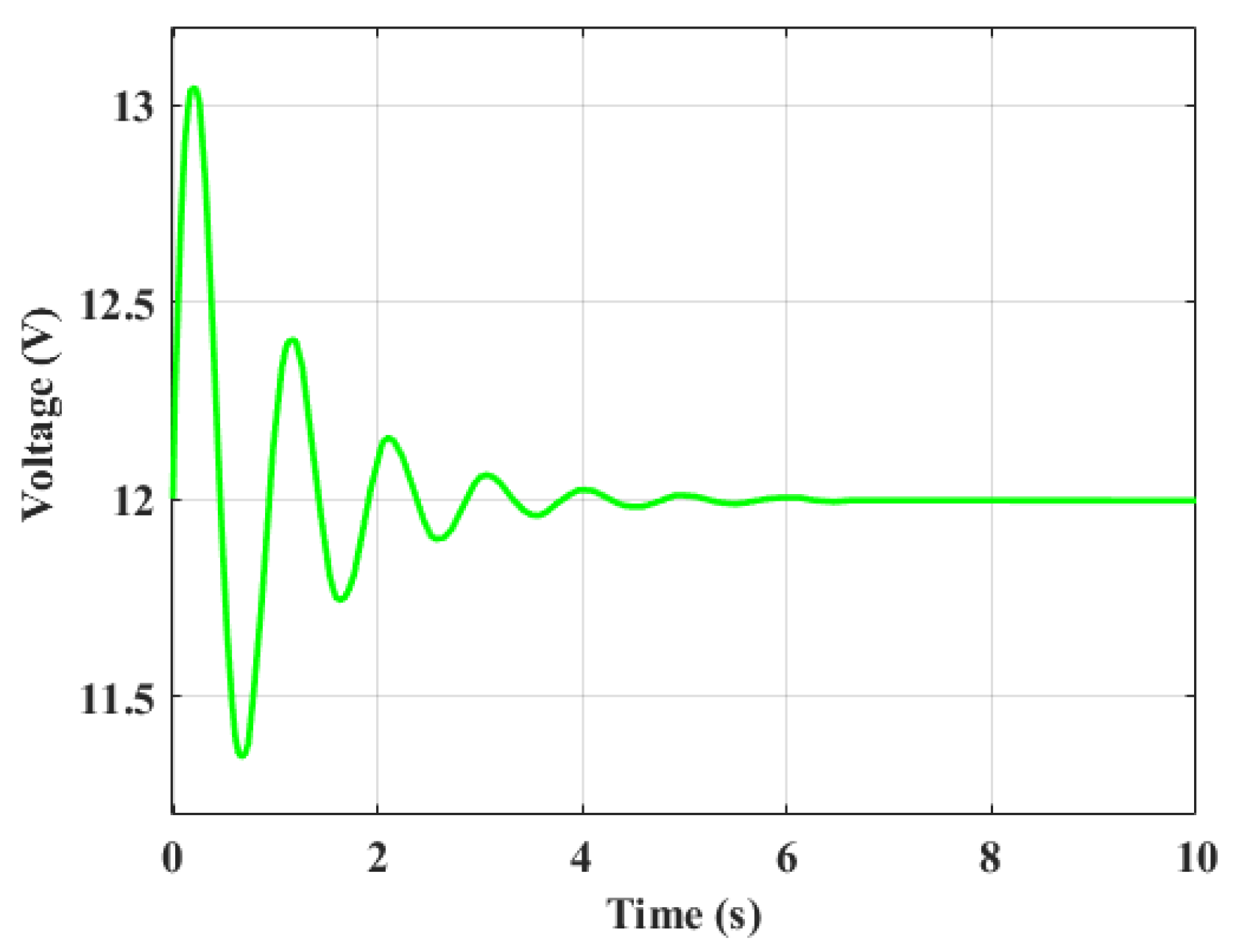
Figure 7.
Performance evaluation of CTA optimized PID controller.
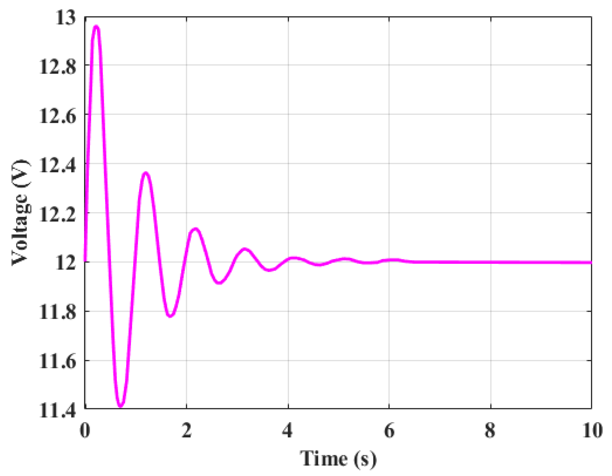
Figure 8.
Performance evaluation of L-based adaptive PID.
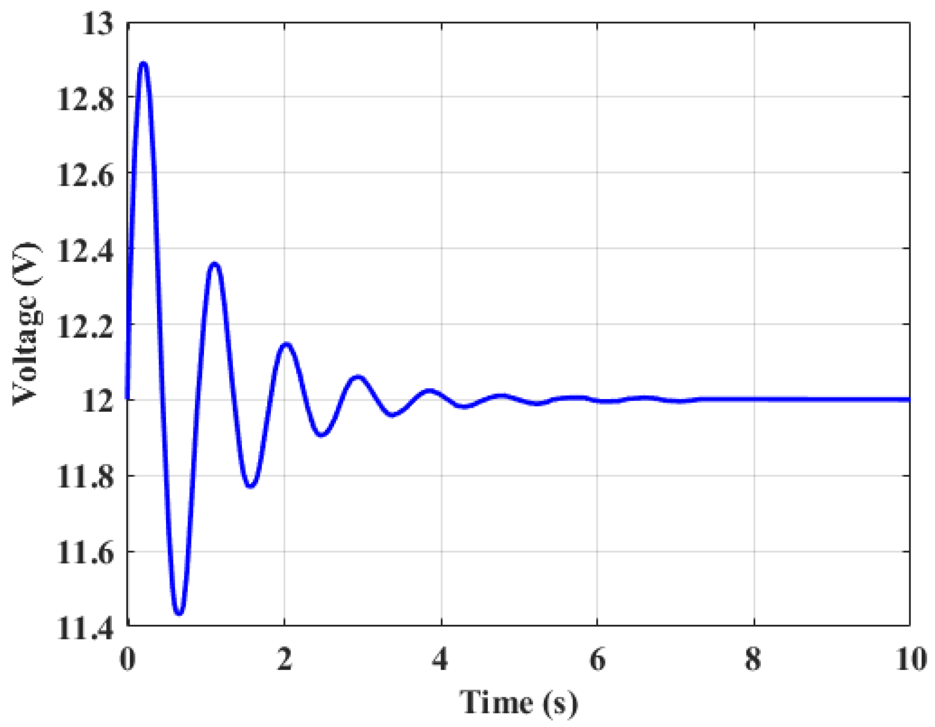
Figure 9.
Performance comparison of various control strategies.
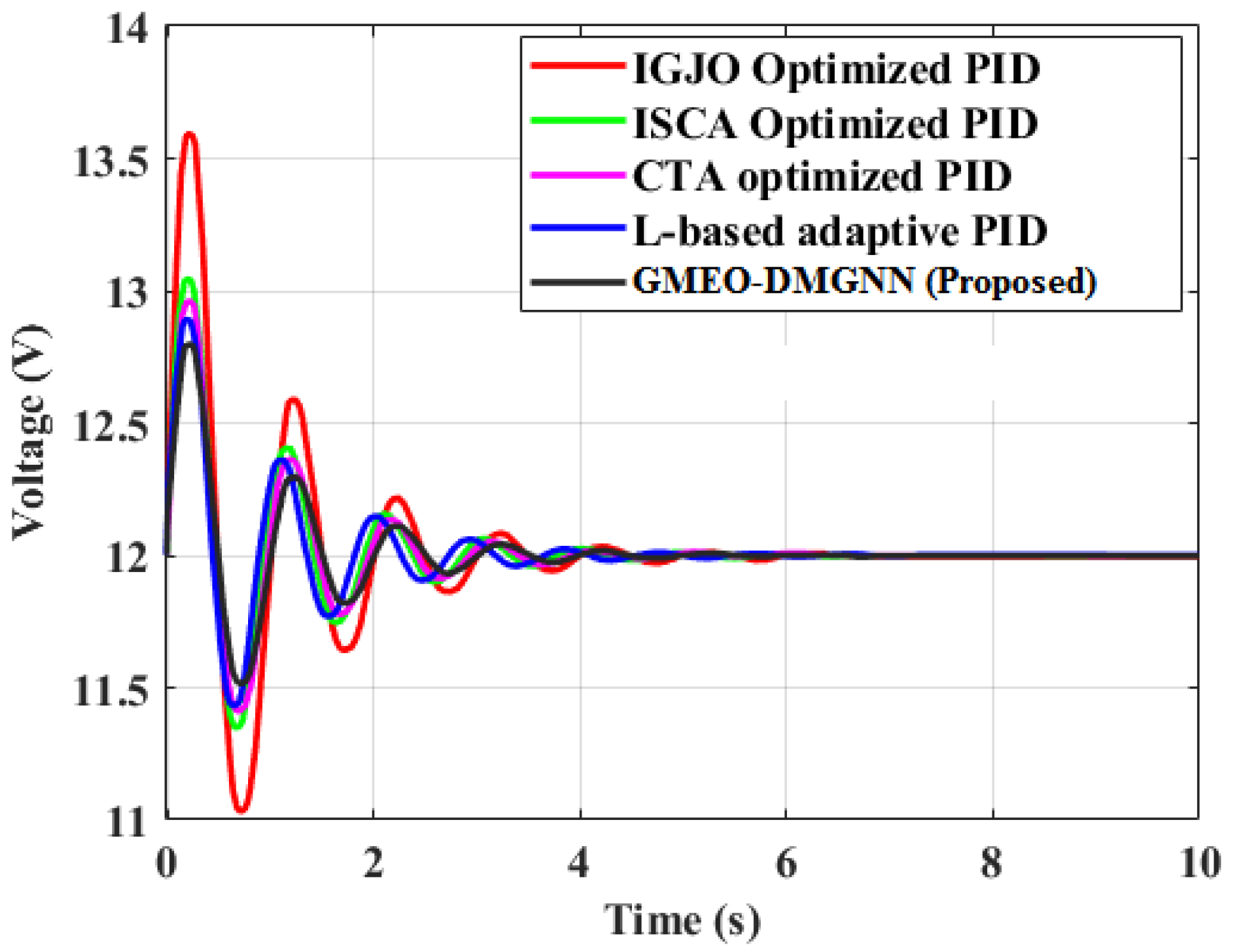

Table 1.
The Summary of Research Work.
| Authors | Methodology | Advantages | Limitations |
|---|---|---|---|
| Sangeetha et al. [21] | Improved Golden Jackal Optimization (IGJO) for PID control | Efficient in power electronic systems, improved fractional-order control | Nonlinear nature of power converters, complexity in controller tuning |
| Warrier et al. [22] | Cohort Intelligence Algorithm for PID control | More robust to parameter variations | Higher parameter complexity, challenging for practical implementation |
| Nanyan et al. [23] | Improved Sine Cosine Algorithm (ISCA) for PID control | Better local optima handling, enhanced PID tuning | Limited to specific types of systems, less efficient for highly nonlinear systems |
| Ghamari et al. [24] | Lyapunov-based model reference PID control | Improved stability, robustness under disturbances | May not work efficiently for rapid dynamic changes |
| Garcia-Chavez et al. [25] | Sliding mode controller with multiple PID loops | Asymptotic stability, robust performance against parameter variations | Increased complexity in tuning and maintaining multiple PID loops |
| Omer et al. [26] | Machine Learning Gradient Boosting-based (MLGB) controller | Dynamic adaptation, reduces need for manual tuning | Not inherently adaptive for fast-changing conditions without retraining |
| AAltbawi et al. [27] | FOPID controller | Improved tuning flexibility | More complex tuning process due to additional parameters |
Table 2.
The system specifications.
| Parameters | Values |
|---|---|
| Input Voltage Range (Vin) | 5V to 15V |
| Output Voltage (Vout) | 12V |
| Maximum Output Current (Iout) | 2A |
| Switching Frequency (fs) | 100 Khz |
| Duty Cycle (D) | 0.2 to 0.8 |
Table 3.
Performance Comparison of PID tuning methods.
| Methods | Settling Time (ms) | Overshoot (%) | Steady-State Error (V) |
|---|---|---|---|
| IGJO Optimized PID | 1000 ms | 25% | 0.15 V |
| ISCA Optimized PID | 500 ms | 15% | 0.05 V |
| CTA optimized PID | 200 ms | 5% | 0.02 V |
| L-based adaptive PID | 150 ms | 3% | 0.01 V |
| GMEO-DMGNN (Proposed) | 100 ms | 1.5% | 0.005V |
Table 4.
The statistical performance comparison of proposed with existing techniques.
| Methods | Mean | Standard Deviation |
|---|---|---|
| IGJO Optimized PID | 4.9876x10⁻⁷ | 6.9452 x10⁻¹² |
| ISCA Optimized PID | 3.2344 x10⁻⁷ | 5.4322 x10⁻¹² |
| CTA optimized PID | 3.9087 x10⁻⁷ | 4.3322 x10⁻¹² |
| L-based adaptive PID | 3.2890 x10⁻⁷ | 5.9880 x10⁻¹² |
| GMEO-DMGNN (Proposed) | 4.0345 x10⁻⁷ | 5.4333 x10⁻¹² |
Table 5.
Comparison of Time-Weighted Absolute Error (ITAE), Integral of Squared Error (ISE).
| Methods | ITAE | ISE |
|---|---|---|
| IGJO Optimized PID | 2.39850000 x10⁻¹³ | 2.73120000x10⁻⁶ |
| ISCA Optimized PID | 2.36580000 x10⁻¹³ | 2.62490000x10⁻⁶ |
| CTA optimized PID | 2.96550000 x10⁻¹³ | 3.52110000x10⁻⁶ |
| L-based adaptive PID | 2.90000000 x10⁻¹³ | 2.43120000x10⁻⁶ |
| GMEO-DMGNN (Proposed) | 2.09998998 x10⁻¹³ | 1.19052756 x10⁻⁶ |
Table 6.
Comparison of efficiency of proposed and existing techniques.
| Methods | Efficiency (%) |
|---|---|
| IGJO Optimized PID | 82% |
| ISCA Optimized PID | 89% |
| CTA optimized PID | 89.6% |
| L-based adaptive PID | 91% |
| GMEO-DMGNN (Proposed) | 98.5% |
Table 7.
Optimal parameters of PID controller.
| Methods | Optimal Kp | Optimal Ki | Optimal Kd |
|---|---|---|---|
| IGJO Optimized PID | 8.01 | 31.2 | 0.11 |
| ISCA Optimized PID | 7.32 | 30.32 | 0.12 |
| CTA optimized PID | 7.99 | 32.31 | 0.30 |
| L-based adaptive PID | 6.43 | 33..21 | 0.21 |
| GMEO-DMGNN (Proposed) | 8.52 | 34.01 | 0.33 |
Disclaimer/Publisher’s Note: The statements, opinions and data contained in all publications are solely those of the individual author(s) and contributor(s) and not of MDPI and/or the editor(s). MDPI and/or the editor(s) disclaim responsibility for any injury to people or property resulting from any ideas, methods, instructions or products referred to in the content. |
© 2025 by the authors. Licensee MDPI, Basel, Switzerland. This article is an open access article distributed under the terms and conditions of the Creative Commons Attribution (CC BY) license (https://creativecommons.org/licenses/by/4.0/).
Copyright: This open access article is published under a Creative Commons CC BY 4.0 license, which permit the free download, distribution, and reuse, provided that the author and preprint are cited in any reuse.


