
Submitted:
09 March 2025
Posted:
10 March 2025
You are already at the latest version
Abstract
This study introduces a novel titanium hollow structure for mandibular reconstruction, designed to optimize mechanical stability and stress distribution. A comparative evaluation with a similar polyetheretherketone (PEEK) structure is performed to assess material-specific biomechanical behavior; Methods: Finite element analysis (FEA) simulations were conducted to evaluate stress distribution, displacement, and structural stability of the symmetrical titanium and PEEK hollow structures under physiological conditions. The reconstructions were designed based on Scherk minimal surfaces, integrating fixing plates to achieve optimal mechanical performance while maintaining symmetry; Results: The titanium structure exhibited superior mechanical stability and more efficient stress distribution, ensuring structural integrity under applied forces. Conversely, PEEK demonstrated greater flexibility, reducing stress shielding but showing limitations under higher loading conditions. While titanium inherently supports osseointegration, PEEK requires surface modifications to enhance bone integration and long-term stability; Conclusions: The titanium hollow structure presents a promising advancement in metal-based mandibular reconstruction, effectively balancing strength, durability, and biological integration. Future research should focus on using more structures, enhancing surface modifications and optimizing lattice structures to further improve the biological and biomechanical performance of PEEK-based and titanium-based implants in load-bearing conditions.
Keywords:
mandibular reconstruction
; Scherk minimal surface
; titanium structure
; PEEK
; finite element analysis
; osseointegration
; stress shielding
; biomechanical performance
; implant materials
1. Introduction
Mandibular reconstruction remains a critical challenge in maxillofacial pathology due to the complex biomechanical and anatomical functions of this essential bony facial structure [1]. Segmental defects often result from oncologic resections, trauma, or aggressive benign conditions such as ameloblastoma [2,3]. Beyond the oncologic implications, loss of mandibular continuity leads to severe impairments in mastication, speech, and facial symmetry, necessitating robust and correct reconstructive solutions [4].
Autogenous bone grafting, particularly the free vascularized fibula flap, is widely regarded as the gold standard for mandibular reconstruction [5,6,7] due to its structural integrity, vascularization, and ability to support osseointegration of dental implants [8]. This technique involves harvesting a segment of the fibula, along with its vascular supply, and transplanting it to the defect site for the reconstruction of bone, soft tissue, or both [9]. However, its application is contraindicated in patients with vascular insufficiency, prior lower limb surgeries, or systemic conditions that compromise healing [10].
Additionally, free flap reconstruction requires complex microvascular anastomosis, often necessitating multidisciplinary surgical teams, which increases both operative time, patient discomfort and morbidity [11].
When autogenous grafting is not feasible, titanium reconstruction plates are commonly employed to stabilize the remaining mandibular segments. Standard fixing methods involve commercially available plates and screws, but these rigid, non-anatomical designs often fail to conform precisely to patient-specific anatomy. This mismatch can lead to mechanical failures such as stress shielding, screw loosening, soft tissue irritation, and plate fractures [12].
Recent advancements in computer-assisted surgical planning (CASP) and custom-made cutting guides have transformed the field of mandibular reconstruction, significantly improving precision, reducing operative time, and minimizing complication rates [6,13]. In response to these challenges, patient-specific implants (PSIs) have emerged as a promising alternative, utilizing computer-aided design and manufacturing (CAD/CAM) technologies to develop customized implants tailored to the unique anatomical and functional requirements of individual patients [14].
Titanium and its alloys are widely used in maxillofacial reconstruction due to their exceptional biocompatibility, corrosion resistance, high strength-to-weight ratio, and favorable osseointegration properties. Unlike other metallic biomaterials, titanium naturally forms a stable oxide layer (TiO₂) on its surface, which enhances cell adhesion, bone ingrowth, and long-term stability in vivo [15,16]. This property facilitates direct osseointegration, where osteoblasts and bone tissue integrate with the implant surface, ensuring firm fixing without the need for additional grafting material [17].
Titanium’s biomechanical properties also contribute to its success in mandibular reconstruction. While it has higher stiffness than native bone, leading to potential stress shielding, its modification through lattice or porous structures can mitigate this effect by optimizing load distribution [18]. Additionally, surface modifications, including nanostructuring, hydroxyapatite coatings, and laser texturing, have been shown to further enhance osseointegration and soft tissue integration, improving overall implant longevity and stability [19].
While solid titanium plates provide mechanical strength, they also introduce several challenges in long-term mandibular reconstruction: increased stiffness may lead to stress shielding, reducing physiological bone remodeling. Also, solid structures increase the load on surrounding tissues, impacting patient comfort. Titanium implants cause streaking and blooming artifacts in CT scans, complicating postoperative tumor surveillance and radiotherapy planning [20].
To mitigate some of these challenges, the development of titanium hollow structures presents a promising approach for segmental mandibular reconstruction. By incorporating engineered porosity, these structures provide [18]:
- -
- Lightweight mechanical stability, reducing the overall implant burden;
- -
- Improved biomechanical load distribution, minimizing stress shielding;
- -
- Enhanced osseointegration, as interconnected porous surfaces support bone ingrowth and vascularization.
In recent years, polyetheretherketone (PEEK) has gained significant attention as a potential alternative to traditional titanium-based implants for mandibular reconstruction. This high-performance polymer exhibits favorable biocompatibility and possesses mechanical properties closely resembling those of cortical bone. This compatibility helps reduce stress shielding effects and ensures a more natural load distribution, which may contribute to improved long-term stability and functional performance of the reconstruction [21].
Additionally, PEEK’s radiolucency provides a notable advantage over metallic implants, as it minimizes imaging artifacts and allows for more precise postoperative monitoring of potential tumor recurrences as well as treatment planning [22]. Its ability to maintain structural integrity while enhancing diagnostic accuracy makes it a promising material for mandibular segmental reconstruction.
Finite Element Analysis (FEA) has been extensively utilized to simulate mandibular biomechanics and assess the performance of different implant designs under physiological loading conditions [23,24,25,26]. However, studies specifically evaluating the biomechanical behavior of hollow titanium structures in mandibular reconstruction remain limited. By leveraging FEA simulations, it is possible to optimize implant geometry, porosity, and mechanical performance, ensuring a balance between strength, flexibility, and osseointegration potential.
This study presents a novel titanium hollow structure designed to restore mandibular continuity without the need for autogenous bone grafting. Using FEA simulations, we evaluate its mechanical stability, load distribution, and potential advantages over conventional solid titanium implants. Additionally, we conduct a comparative assessment of the same hollow structure fabricated from PEEK to analyze the impact of material properties on biomechanical performance. This comparison aims to determine the suitability of PEEK as an alternative to titanium in mandibular reconstruction, particularly regarding stress distribution, deformation patterns, and overall structural integrity. The findings seek to contribute to the advancement of more efficient, durable, and biologically favorable reconstruction strategies for patients with segmental mandibular defects.
2. Materials and Methods
2.1. Refinement of the Mandibular Testing Model
The mandibular model used in this study for finite element simulation was identical to that described in a previously published study [23]. To evaluate various reconstruction strategies for a right segmental mandibular defect following ameloblastoma resection, a Standard Tessellation Language (STL) file was generated, representing a healthy adult male mandible. This file was obtained by segmenting the mandible from a cone beam computed tomography (CBCT) scan in Digital Imaging and Communications in Medicine (DICOM) format.
As a computational study based solely on numerical simulations, this FEA does not require ethical approval, as it does not involve human or animal subjects.
The primary segmented mandibular model generated a highly detailed and complex STL file, requiring simplification, refinement, and editing. This refinement was performed using CATIA V5R21 (Dassault Systèmes, France), a specialized software for complex surface modeling.
Upon import into CATIA V5R21, the STL file underwent an initial surface validity check, followed by simplification using the DMU Optimizer workbench. This tool offers multiple optimization options, applied according to the complexity and morphology of the analyzed surface. By utilizing the Simplification tool, the scanned mandibular surface was optimized, reducing the number of triangles from an initial 836,400 to 151,000. This reduction resulted in a more computationally efficient 3D model, suitable for subsequent processing steps and FEA. However, despite this optimization, the surface retained a relatively high level of complexity for a model of mandibular dimensions, allowing for further refinements and modifications necessary to create a precise CAD model.
Following this initial simplification, the model was exported in .model format, consisting of approximately 150 distinct patches, each containing hundreds or thousands of triangles (Figure 1). These patches were highly detailed, with edge dimensions ranging between 0.3 mm and 1.5 mm, covering the entire mandibular surface. The authors meticulously ensured that all surface patches were connected, free of self-intersections, without missing triangles, and devoid of errors caused by the STL file export-import process.
Figure 1 illustrates a fragment of the specification tree within CATIA V5R21, displaying the default naming conventions for the triangles as they appear in the .model file, designated as MASTER.
These patches are merged into a single surface using the Join tool within the Generative Shape Design workbench to facilitate manipulation, eliminate selection errors, and enhance the cohesion of the 3D model. Depending on the computational power of the system used for processing, the merging of patches can take anywhere from a few minutes to over an hour. This is because CATIA V5R21 systematically verifies each individual patch and its connections with adjacent patches, followed by a secondary simplification of the resulting geometry.
This secondary simplification does not compromise the level of detail in the model; instead, it corrects tangency conditions between connected triangles, adjusting their size to ensure complete surface coverage while preserving full geometric integrity.
Typically, the scanning of an organic surface with such complexity does not yield a flawless result, leading to localized areas that require additional refinement and editing. One such example is observed in the condylar region (Figure 1). Minor imperfections, such as missing triangles, are automatically corrected by the software, whereas manually guided interventions are necessary when the affected area contains self-intersecting triangles or unintended geometric distortions.
The elimination of imperfections is a critical step, as failure to do so often prevents the conversion of the surface into a solid model and may negatively impact FEA results. Ensuring a geometrically sound and well-defined surface is essential for accurate simulation and analysis. The identification and correction of these areas represent challenging steps in the processing workflow. However, CATIA V5R21 includes a variety of tools within the Shape Sculptor workbench specifically designed for mesh editing at the level of points, edges, and triangles.
Using the Join tool, all triangles are grouped at the edge level to form a closed surface, effectively generating a mesh. Subsequently, the Tessellate function is applied with a sag value of 0.05 mm to simplify and refine the mandibular surface. The tessellation process computes a geometric discretization of curves, surfaces, edges, and faces, allowing for their use in visualization, mesh editing, and reconstruction.
Since the mandibular model was generated automatically through segmentation of the CBCT scan, without prior surface refinement, its initial form appears as shown in Figure 2a. The surface exhibits a relatively rough texture with an excessive number of triangles, which, when used in FEA, would introduce an unnecessarily large number of elements. These additional elements do not enhance simulation accuracy but rather increase computational resources and processing time.
To address this issue, the authors deemed it necessary to eliminate redundant surface details by applying the Mesh Smoothing tool. This refinement process smooths the surface, resulting in a more anatomically realistic mandibular model, as illustrated in Figure 2b.
In Figure 2, the complexity and organic morphology characteristic of the mandible, particularly in the alveolar process region, including the mental foramen, can be observed. Although the model has undergone several simplification and editing steps, the anatomical integrity of the mandible has been preserved, ensuring highly accurate results in the FEA.
From the Quick Surface Reconstruction workbench, the Automatic Surface tool was applied with the following parameters: Mean surface deviation = 0.5 mm, Surface detail = 12,000, and Target ratio = 95 (Figure 3). This tool is adapted to various surface types, allowing for the reconstruction of complex geometries, and it can generate surfaces with or without complete internal tangency between adjacent faces.
The applied parameters ensure a high level of detail retention for the mandibular surface, while allowing for a slight simplification through the adjustment of the Target Ratio parameter. Empirical evidence suggests that a Target Ratio approaching 100 is unnecessarily time- and resource-intensive, without providing any significant improvement in the discretization of the mandibular model.
Following the completion of the entire procedure, as detailed in [23], a solid body is generated using the Close Surface tool within the Part Design workbench. This solid model is then transferred to the FEA.
Additionally, the authors have created a video tutorial demonstrating the entire process of converting the scanned surface into a solid model ( https://youtu.be/DAt7YAio2A0 accessed on 10.02.2025).
2.2. Design of the Hollow Structure
A critical component of the studied assembly is the mandibular reconstruction part, which exhibits high structural complexity and is designed using a Triply Periodic Minimal Surface (TPMS) structure. These surfaces possess exceptional mechanical properties, including high specific strength against forces, moments, and pressures, as well as efficient stress absorption due to their non-positive Gaussian curvature geometry.
Some of the most well-known TPMS structures include honeycomb, gyroid, lidinoid, Schwarz, Scherk, Neovius, and Kelvin lattice [27,28].
Due to their method of generation and representation, these surfaces exhibit symmetries characteristic of a spatial or crystallographic group. In mathematics, physics, and chemistry, a spatial group refers to a set of symmetrically arranged elements that form a repeating pattern in three-dimensional space, following a specific law or geometric rule.
The symmetries of a TPMS allow the surface to be constructed from a single asymmetric surface patch, which extends and replicates across the entire structure through symmetry operations involving specific planes or edges of adjacent patches. The primary symmetries in minimal surfaces are generated by Euclidean reflections in mirror planes and two-fold rotational transformations. These symmetries can be readily identified in the geometry of a minimal surface. Mirror planes result in planar lines of curvature, where the principal directions of the surface lie within a plane. In contrast, two-fold rotation axes on the surface appear as straight asymptotic lines.
Numerous examples of surfaces exhibiting cubic, tetragonal, rhombohedral, and orthorhombic symmetries have been documented. Some of these surfaces can be parametrically generated using mathematical equations [29], while others have been observed in nature, such as in biological membranes [30], block copolymers [31], and equipotential surfaces in crystalline structures [32,33]. However, some of these structures are highly complex and difficult to model or replicate in computational environments.
TPMS structures have gained widespread interest in military applications, the automotive and aerospace industries, architecture, design, and art, due to their optimal mechanical properties, lightweight nature, and structural efficiency.
The mandibular reconstruction part is based on a Scherk-type Minimal Surface (example [34]).
The German mathematician Heinrich Ferdinand Scherk first described two complete embedded minimal surfaces, in 1834. His first surface is a doubly periodic surface, while his second surface is singly periodic. These were the third set of non-trivial examples of minimal surfaces in mathematical history [35].
Scherk's work is considered a continuation of the research initiated by Jean Baptiste Marie Meusnier, who discovered the first two minimal surfaces, namely the catenoid and the helicoid, in 1776. These two surfaces are conjugate to each other, meaning they are mathematically related through a transformation that preserves minimal surface properties [36].
The modeling of the Scherk surface begins with the construction of a 100 × 100 × 100 mm cube. In the base plane, two circular arcs with a radius of R50 mm are drawn, with their centers positioned at two diagonally opposite corners of the cube. The diagonal line connecting these two corners intersects the circles at two points. Through these intersection points, a circle is drawn in a plane perpendicular to the base plane.
As illustrated in Figure 4, the representation is further refined by adding two additional lines:
- -
- A vertical line positioned on the right -side face of the cube;
- -
- A horizontal line that connects the end of the vertical line to the upper quadrant point of the circle.
To finalize the geometric construction, the Split and Trim tools from the Generative Shape Design workbench are applied. These operations eliminate unnecessary wireframe support structures, retaining only the contour highlighted by the thick line for further modeling.
Figure 5 presents two support surfaces generated by extruding the vertical line and the circular arc from the profile highlighted in Figure 4. These support surfaces play a crucial role in the next modeling step: the creation of a multi-sections surface.
The surface is constructed between two sections, S1 and S2, along two guiding curves, and it is tangent to the support surfaces. This tangency condition ensures the generation of a surface that can be replicated through symmetry and rotation relative to specific planes and edges. The initial surface is then mirrored to the left with respect to a reference plane, producing a second symmetrical surface, as shown in Figure 5.
The pair consisting of the initial surface and its first symmetrical counterpart (highlighted in Figure 6) are then duplicated through rotation around two edges as well as the Z-axis. A rotation angle of 180° is applied to generate three additional surfaces, completing the intended structure.
The group of surfaces shown in Figure 6 represents half of the main surface of the structure. To obtain the final surface, the group is mirrored with respect to a horizontal symmetry plane passing through any three points located on the upper edges.
Figure 7 illustrates the main surface along with the symmetry plane.
The main surface, also referred to as the core surface, is thus constructed from the initial multi-sections surface, which has been replicated through rotation and symmetry operations. This main surface can be further duplicated using translation, rotation, and symmetry transformations to generate a complex structure, as illustrated in Figure 8, which is presented in two isometric views.
The continuity and connectivity of the structure, composed of individual surfaces, allow for their integration into a single unified surface through a joining operation.
This Join phase is a critical step, as the surface structure must be converted into a solid structure by applying a thickness parameter. The assigned thickness value for the resulting solid model is approximately 2 mm, considering the initial dimensions of the wireframe cubic structure that supported the initial multi-section surface.
Given the construction methodology, including the curved surfaces, connection conditions, and tangency constraints between the component surfaces, the resulting structure can be classified as a hollow lattice structure (Figure 9). Such lattice structures are characterized by their lightweight design, high customizability, and favorable mechanical properties, primarily due to their hollow rounded geometries, as discussed in the review by Chibinyani et al. [37].
The entire process of generating this Scherk surface and the solid structure is presented in detail in the video material available at the following link: https://youtu.be/ZiKzNJjNzs0 accessed on 10.02.2025.
2.3. Design of the Mandibular Reconstruction Part
The obtained structure must be scaled and trimmed to precisely fill the 23 mm gap created by the mandibular bone resection. Consequently, the structure must closely conform to the shape of the missing bone segment. The two cutting surface sections (also referred to as trimming surfaces) are designed to match the morphology of the mandible. Additionally, multiple guiding curves are defined between these sections to ensure an accurate adaptation.
Figure 10 provides two visual representations of the solid structure. On the left, the two sections, several guiding curves, and the cutting surface are displayed, while on the right, the final solid structure is shown. Throughout the modeling process, the authors carefully ensured that the trimming process was conducted accurately, preventing thin-walled regions, large voids in the upper area, sharp edges, or any other geometric inconsistencies.
Following scaling and refinement, the final structure has a thickness of 0.84 mm, while the maximum hole diameter reaches 3.4 mm. The resulting design is a dense and robust structure, exhibiting distinct symmetries and organic-like patterns and aspect.
At both ends of the structure, narrow planar surfaces can be observed, which are intended to be in direct contact with the mandibular bone. Additionally, contact surfaces are located on both the superior and inferior areas, where the structure interacts with soft tissues. These surfaces may pose a high risk of bone and soft tissue erosion, even if the structure is mechanically fixed to the mandible bone using screws.
Several strategies can be employed to mitigate these risks. The authors propose incorporating additional complementary contact surfaces on the structure to improve bone and soft tissue adaptation. Moreover, the use of a resorbable barrier membrane to cover the structure at the time of placement within the mandibular defect is recommended to enhance tissue compatibility and integration. Given its high biocompatibility, titanium may further contribute to osseointegration, facilitating stable and long-term bone reconstruction [18].
Figure 11 presents two isometric views of the structure after the addition of planar surfaces at its ends and base, as well as curved surfaces in the upper region. In this area, the thickness is set between 1.8 and 2.2 mm to accommodate the insertion of screw-type dental implants. The added surfaces enhance the structural rigidity and ensure the appropriate distribution and transmission of stresses exerted on the mandibular bone under functional loading conditions.
To achieve secure fixing of the reconstruction onto the mandibular bone, the structure depicted in Figure 11 is further reinforced with two integrated plates. These plates are custom-designed to match the patient’s mandibular anatomy in the contact region, with a width of 6.9 mm and a thickness of 1.2 mm, as determined by previous analyses published in an earlier study [23]. The reduced thickness of these plates contributes to enhanced patient comfort.
Figure 12 presents the final solid model of the proposed structure for mandibular reconstruction. Additionally, each fixing plate hole is annotated with its corresponding screw specifications. The edges in contact with soft tissues have been rounded to minimize the risk of tissue damage.
Regardless of the rigidity of the structure and the mechanical fixing method used to secure the reconstruction part to the mandibular bone, minor displacements and friction will inevitably occur due to bone torsion and plate movement. The incorporation of planar smooth surfaces increases the contact area, thereby reducing localized stress on the bone and enhancing uniform load distribution.
The objective of such a complex structure, even if not entirely flawless, is to absorb and redistribute mechanical stresses within its structure, thereby minimizing stress concentrations at the bone-reconstruction interface. Its shape, closely matching that of the resected bone, ensures optimal filling of the defect and presents a viable alternative to current solutions that rely on autogenous bone grafting.
Figure 13 illustrates the final shape of the reconstruction part, which restores the structural integrity of the mandible, re-establishing its continuity following resection. The component is secured to the mandibular fragments using six screws, strategically positioned to restrict degrees of freedom, thereby minimizing displacements and deformations.
A key aspect highlighted in this study pertains to the alignment of the screw hole axes in both the bone and fixing plates. These axes are neither parallel nor coplanar (Figure 14), significantly reducing the risk of screw loosening or detachment from the assembly over time.
The modeling of both the mandible and the reconstruction structure is a crucial step in preparing the assembly for FEA. The resection was done at the body of the mandible (in quadrant four, right side, distal to the mental foramen, in the molar region) over a distance of 23 mm. The resected zone is perpendicular to the occlusal plane and guided to ensure that the two resulting planar surfaces are parallel.
2.4. FEA Simulation: Titanium Versus PEEK
The present study considers two possible clinical scenarios, both related to the material selection for the reconstruction part. The reconstruction may be manufactured from either:
Ti-Grade-4 alloy (TI75A) with the following physical properties:
Young's modulus: 104,000 MPa; Poisson’s ratio: 0.34; Density: 4,500 kg/m³; Yield strength: 550 MPa; or
PEEK (Polyetheretherketone) with the following physical properties: Young's modulus: 3,900 MPa; Poisson’s ratio: 0.42; Density: 1,300 kg/m³; Yield strength: 100 MPa.
Figure 14 provides a detailed representation of the positioning of the reconstruction part, which restores mandibular continuity and compensates for the defect. The structure is secured using six Ti-Grade-4 (TI75A) standard screws.
Both components can be fabricated using additive manufacturing technologies, allowing for customized production tailored to each clinical case. Additionally, parametric modeling of the structure enables the development of a standardized family of reconstruction parts, which can be generated using modern CAD software such as CATIA V5R21 within predefined size ranges.
However, the trimming of the structure and the addition of fixing plates are patient-specific steps, requiring individual customization based on mandibular shape and dimensions. The precise fit of the fixing plates and the entire reconstruction part ensures both enhanced stability and improved patient comfort. Nonetheless, the time required for the design process is significantly reduced, as clinicians can rapidly select appropriate dimensions and orientation from pre-defined models, eliminating the need to redesign the structure from scratch for each case.
The reconstruction is secured to the remaining mandibular fragments using six standard screws with a diameter of 2 mm and a length of 5 mm, made from the same Ti-Grade-4 (TI75A) alloy. The figures above illustrate the detailed modeling of the structure, integrated fixing plates, and screws, with dimensions and component shapes determined through an extensive literature review and successive iterations. These refinements aimed to eliminate potential design flaws early in the conceptualization and design phase, such as insufficient structural thickness or sharp points and edges that could cause soft tissue damage.
The articular cartilage at the temporomandibular joints (TMJs) was precisely modeled, with a thickness of 1 mm and the following material properties: Young’s modulus: 30 MPa, Poisson’s ratio: 0.29, Density: 1300 kg/m³, and Yield strength: 5 MPa [38]. The TMJs were assigned elasticity and relative motion properties with respect to the maxilla, which are crucial parameters in the FEA.
The mandibular bone, the primary structural component in the studied assembly and a key anatomical element for the patient, was assumed to have a homogeneous and compact structure to simplify the FEA process [23]. This represents the main limitation of the proposed model; however, the authors believe that the accuracy of the results is not significantly affected.
For the material assigned to the bone, average values of physical properties were selected: Young’s modulus: 13,000 MPa, Poisson’s ratio: 0.30, Density: 1500 kg/m³, and Yield strength: 140 MPa.
To construct the assembly in CATIA V5R21, multiple dimensional and geometric constraints were established within the Assembly Design workbench, ensuring the correct positioning of all components. These constraints include coincidence conditions, surface contact constraints, and distance constraints between specific edges, points and/or surfaces. The assembly process is an important step in developing an accurate FEA model, as it defines the geometric relations between the components involved in the study. The applied constraints restrict the degrees of freedom of the mandible, articular cartilage, reconstruction part, and screws, ensuring a stable and realistic simulation environment.
The FEA of the entire assembly is performed within the Generative Structural Analysis workbench. Each solid component is discretized using finite elements, considering both the required level of detail and the computational resources needed for the FEM computations.
Meshing a solid model involves approximating the real physical structure using hundreds or thousands of simple geometric elements that are interconnected along edges and points, known as nodes. The resulting mesh provides a viable mathematical representation of the actual assembly components, ensuring an accurate simulation of structural behavior under different loading conditions.
Based on the authors' expertise, it can be stated that a higher level of discretization (meshing level) generally yields more accurate simulation results. However, beyond a certain threshold, increasing the number of finite elements no longer significantly enhances the quality of the results [39,40]. The primary impact of an excessively fine mesh is observed in terms of increased computational time required for simulation.
Additionally, for small components or areas where the geometry is highly complex (such as the alveolar process of the mandible or the contact interface between the reconstruction structure and the fixing plates), localized discretization can be applied to enhance accuracy without significantly increasing the computational load.
Each component of the studied assembly is meshed according to its size, shape, and functional role, with the main discretization parameters summarized in Table 1.
Table 1 indicates that most components are discretized using parabolic finite elements, except for the screws, which are modeled with linear elements. Linear elements have a simpler geometric shape and node connectivity, resulting in a linear displacement interpolation. Under loading conditions, these elements exhibit linear deformation between nodes. However, when complex curved surfaces are involved in a FEA, higher-order elements (e.g., parabolic or cubic elements) should be applied. When subjected to external loads, these elements follow parabolic deformation equations, as they contain additional nodes along the edges between the primary nodes. This enhances mesh complexity, potentially improving accuracy and reducing error rates, but at a cost of greater computational time [23].
The components of the mandibular assembly are incorporated into the FEA model by defining physical connections (Figure 15) between surfaces in contact. Due to the high complexity of this model, connections are established carefully and in detail to ensure accuracy. The FEA simulation presented in this study incorporates Smooth, Rigid, Contact, General, and Fastened connections. When correctly implemented, these connections provide a highly accurate representation of real-world mechanical behavior.
Figure 15 presents a detailed example of the contact between a screw surface and its corresponding hole in the mandibular bone, highlighting the connection established within the finite element model. Since no relative movement should occur between these two surfaces, a Rigid connection is applied, ensuring that the screw remains firmly secured within the bone. The green lines in Figure 15 indicate various physical connections between the screws, fixing plates, and mandible. Additionally, the specification tree displays a subset of these connections, as generated and visualized within CATIA V5R21.
More than 50 physical connections were established between the surfaces of the assembly components, ensuring structural coherence and simulation accuracy.
The upper surfaces of the TMJs are constrained to prevent displacement and/or rotation of the finite elements and nodes located on them. Consequently, all six degrees of freedom are fully restricted.
Several forces are applied to the mandibular surface to simulate the muscle actions involved in mandibular movement, including the masseter, temporalis, pterygoid muscles, and suprahyoid musculature. In this study, the authors simplified the loading conditions and excluded masticatory forces, as the analysis was performed on an edentulous mandible, which will later be restored with a removable denture.
Four specific force application zones (A–D) were defined on the mandible, as illustrated in Figure 16. Forces B, C, and D are assumed to be symmetrical. The forces are distributed as follows:
Force A, generated by the suprahyoid muscles, is applied to the mental region with a magnitude of 30 N. Forces B, C, and D, corresponding to the temporalis (12 N per side), masseter (40 N per side), and medial pterygoid muscles (30 N per side), are applied to each hemimandible (Figure 16).
The direction of the applied forces closely aligns with the natural orientation of the aforementioned muscles. However, these forces can be decomposed into components along an XYZ coordinate system for further analysis.
These initial force values serve as a baseline, but the study will also examine scenarios involving higher force magnitudes. By simulating various loading conditions, the mandible and reconstruction behavior can be assessed under different mechanical constraints.
Although the analyzed mandible exhibits a certain degree of symmetry, the stresses induced by the applied forces will not be identical in similar anatomical regions (e.g., condyle, mental region, etc.). This asymmetry arises from the mandibular resection and subsequent reconstruction, which alters the stress distribution and mechanical continuity of the structure.
Through successive iterations of FEA, the stress and displacement values induced in all components of the assembly are determined.
The present study comparatively evaluates the reconstruction made from both titanium alloy and PEEK under varying force magnitudes, as illustrated in Figure 16.
The FEA was performed on a computer system equipped with a 13th Gen Intel Core i7-13620H processor (2.40 GHz), a 64-bit Windows 10 operating system, a x64-based processor, and 16 GB of RAM.
3. Results
In the initial phase of the study, the maximum stress and deformation values for the Ti-Grade-4 (TI75A) reconstruction are presented in Table 2, which also includes the maximum stress values identified in the other components.
The table shows significant displacement values for both the mandible and the reconstruction part. As this one moves in tandem with the mandible, it absorbs some of its displacement. The greatest displacement occurs in the mental region of the mandible. Under the applied forces, the reconstruction part experiences deformation and torsion, with the highest stress concentrations observed in the lower region of the fixing plates, as illustrated in Figure 17.
For the five tests presented in Table 2, there is no risk of plastic deformation of the reconstruction, as the maximum stress (172 MPa) remains below the yield strength (550 MPa) of the titanium alloy. However, in this scenario, the stress value in the articular cartilage of TMJ 1 approaches its maximum limit of 5 MPa.
The designed structure, manufactured from titanium alloy, proves to be sufficiently rigid internally. However, it accumulates external stresses, particularly in the fixing plates areas, as well as in regions with reduced thickness or abrupt cross-sectional changes resulting from the trimming surface illustrated in Figure 10. These issues primarily arise from the geometric 3D model, which, if necessary, can be adjusted by incorporating additional reinforcements, modifying the positioning, or altering the shape of the fixing plates, among other refinements.
The proposed model in this study includes two integrated fixing plates with an approximately symmetrical design.
Table 2 shows that the calculated stresses for the mandible and screws are relatively low compared to the yield strengths of the materials used in these components. This is primarily due to the structure of the reconstruction part, which absorbs the applied loads.
In Figure 18, the stress distribution on the mandible is shown in the assembly region with the fixing plates and in the left condyle area. The highest stress values are identified at the contact interface with the reconstruction part, but they do not pose any risk to the structural integrity of the bone in that region. The screws exhibit very low stress levels, ensuring secure fixing within the mandibular bone and minimizing the risk of loosening or unscrewing.
By adjusting the stress scale of the reconstruction part to match that of the mandibular stress display, Figure 19 provides a comparative representation of the structural load distribution and, more importantly, the relatively uniform deformation of the reconstruction part due to its optimized and hollow design. The two planar contact surfaces between the reconstruction part and the mandibular bone prove effective in distributing stresses over a larger and more uniform area, reducing localized stress concentrations at the bone-implant interface.
Regarding the displacements observed in this FEA model, the maximum values are located in the mandible, specifically in the mental region, at the assembly interface with the reconstruction part and around screws 4, 5, and 6, as shown in Figure 20.
The authors consider the FEA simulation results to be accurate, confirming that the Scherk structure adequately compensates for the missing bone fragment, making it a more suitable solution compared to reconstructions that rely solely on fixing plates.
In the second part of this study, FEA simulations were conducted under the assumption that the mandibular reconstruction part is fabricated from PEEK. The same force values from the previous table were applied to ensure comparability between the titanium and PEEK reconstructions.
The results of the FEA for the PEEK-based reconstruction are presented in Table 3, offering a direct comparison with the Titanium Grade-4 (Ti-Grade-4) reconstruction part examined in the first phase. This comparative analysis aims to evaluate material-dependent differences in stress distribution, displacement, and structural performance under identical loading conditions.
Among the five tests conducted for the PEEK reconstruction, only the first three tests are considered acceptable. Tests 4 and 5 exhibit stress values in TMJ 1 and within the reconstruction part itself that are close to or exceed the material's yield strength limits, rendering these scenarios impractical.
Compared to the Ti-Grade-4 reconstruction, PEEK demonstrates greater elasticity, which results in lower stress values across all components. However, this increased elasticity also imposes a limitation on the magnitude of loads that can be applied to the mandible without compromising structural integrity.
The stress distribution and displacement patterns observed in the PEEK reconstruction are similar to those illustrated in the previous figures, with maximum values occurring in approximately the same regions as in the titanium reconstruction.
A comparative table of the masses of the components used for mandibular reconstruction has also been created (Table 4). This comparison provides insight into the weight differences between the Titanium Grade-4 and PEEK reconstructions, which can influence biomechanical performance, patient comfort, and long-term functionality.
4. Discussion
Mandibular reconstruction poses distinct challenges, including stress variations arising from complex functional loads and movements, the anisotropic nature of its bony structures, and differential stress distribution in load-bearing regions, influenced by its shape, morphology, and muscle attachments.
To the best of the authors' knowledge, this is one the first studies to design a mandibular reconstruction structure based on a Scherk minimal surface and to evaluate its biomechanical behavior through finite element analysis (FEA). This novel approach aims to optimize mechanical performance while reducing weight, material usage, and stress shielding effects, which are common concerns in implant-based reconstructions.
This study examines the biomechanical performance of a titanium hollow structure and a comparable PEEK structure, assessing their respective advantages and limitations through FEA simulations. The findings provide critical insights into the feasibility of these materials for segmental mandibular defect reconstruction.
Titanium and its alloys have long been considered the gold standard for mandibular reconstruction due to their excellent biocompatibility, mechanical strength, and osteoconductive properties [41]. Porous titanium structures have garnered increasing interest for their potential to facilitate bone ingrowth and enhance osseointegration [42]. The integration of bone with porous titanium implants follows a well-established biological process encompassing five phases: blood clotting, immune response, angiogenesis, osteogenesis, and osseointegration. This sequence is analogous to the physiological bone healing process following fractures, except that callus formation is absent [43].
Upon implantation, a blood clot forms at the bone-implant interface, initiating a cascade of immune responses and growth factor release, leading to the development of vascular networks (angiogenesis) and new bone formation (osteogenesis) [44]. Osseointegration, the final phase, is characterized by the direct structural and functional connection between the implant and surrounding bone [45]. Studies indicate that the extent of osseointegration directly influences the long-term functional loading capability of the implant.
The architecture of porous titanium significantly impacts its osteointegration potential. Factors such as pore size, shape, porosity, interconnectivity, and surface roughness influence cell differentiation, bone ingrowth, and overall osseointegration [46,47]. Studies suggest that pore sizes ranging from 500 to 1000 μm and porosities exceeding 60% optimize osteogenesis [48,49]. In vivo investigations utilizing micro-computed tomography (μtCT) and histological analysis have demonstrated successful bone ingrowth into lattice constructs with pore sizes between 300 and 900 μm and porosities of 70-84% [18,50]. Furthermore, mechanical testing using push-out and pull-out analyses has confirmed that higher levels of integration correspond to increased force resistance, supporting the long-term stability of the implant [51].
In the current study, the titanium hollow structure demonstrated superior biomechanical performance by effectively distributing loads, reducing stress shielding, and maintaining stability under various functional forces. The lattice configuration promoted uniform deformation, preventing stress concentrations in critical regions. The fixing plates integrated into the structure contributed to enhanced load transfer, minimizing localized stress accumulation. The Scherk-based structure proposed in this study features controlled porosity, designed to achieve an optimal balance between mechanical strength and biological integration. Future studies focusing on osteoblast ingrowth and cellular response will further refine the porosity parameters to enhance osseointegration and biomechanical performance.
Additionally, this study explores the feasibility of using PEEK as an alternative to titanium, addressing concerns related to stress shielding and imaging artifacts. Although PEEK demonstrates promising biomechanical properties, its limited osseointegration potential necessitates surface modifications, such as titanium oxide coatings, to enhance osteoblast adhesion and new bone formation.
To address this limitation, surface modifications have been investigated to enhance osteoblast adhesion and promote bone integration. Bioactive coatings, such as titanium oxide, hydroxyapatite, polydopamine chelated with magnesium ions (Mg²⁺), and plasma-sprayed calcium phosphate, have been applied, among others, to PEEK implants to improve their osteoinductive and osteoconductive properties [52]. In a recent study, customized porous PEEK mandibular analogs were fabricated via 3D printing and coated with titanium oxide to promote bone ingrowth. Histological analysis following implantation in rabbit mandibles confirmed improved osseointegration at 1-, 2-, and 3-month intervals [53].
PEEK exhibits low hydrophilicity, which can limit osteoblast adhesion and bone formation. Enhancing this property through surface treatments can improve cell attachment, proliferation, and mineralization, ultimately promoting bone integration within the porous structure [54].
These findings suggest that surface modification strategies can significantly enhance the clinical applicability of PEEK in load-bearing mandibular reconstructions.
4.1. Comparative Analysis of Titanium and PEEK Reconstructions
The FEA simulations in this study revealed distinct biomechanical behaviors between the titanium and PEEK hollow structures. While both materials successfully restored mandibular continuity, some differences were observed in stress distribution, deformation patterns, and structural integrity under varying load conditions.
Titanium exhibited higher stiffness and resistance to deformation, ensuring long-term stability. However, its increased rigidity also contributed to stress concentrations at fixing sites. Conversely, PEEK’s increased flexibility allowed for greater deformation, which could reduce stress shielding but might compromise structural integrity under high loading conditions.
The titanium structure efficiently dispersed functional loads, minimizing peak stress regions and ensuring uniform force transfer. In contrast, PEEK exhibited lower stress values across all components, attributed to its elastic properties, but with limitations on the magnitude of forces it could withstand.
Titanium inherently supports direct osseointegration, whereas PEEK requires surface modifications to achieve comparable results. The lattice design of both structures improved loads distribution, but the bioactive surface coatings on PEEK implants could enhance cellular response and bone ingrowth.
4.2. Clinical Implications and Future Directions
The findings of the present study underscore the potential of titanium hollow structures in segmental mandibular reconstruction, offering a balance between mechanical strength and osseointegration potential. However, the stress shielding effect of titanium remains a concern, necessitating further optimization of lattice structures to achieve biomechanical equilibrium.
PEEK presents a promising alternative due to its bone-mimetic mechanical properties and radiolucency. However, its lower osseointegration capacity necessitates surface modification strategies to enhance clinical efficacy. Future research should focus on optimizing PEEK-based reconstructions through advanced surface treatments, composite material integration, and long-term in vivo validation.
4.3. Limits of the Present Study
This study has several limitations. First, the FEA simulations were conducted using idealized mandibular geometries, which may not fully capture the anatomical variability encountered in clinical cases. Individual differences in bone density, morphology, and defect size could influence the biomechanical performance of the proposed reconstruction.
Second, the material properties of the mandible, and reconstruction structures were assumed to be homogeneous and isotropic, whereas biological tissues exhibit anisotropic and heterogeneous behavior. This simplification may not entirely reflect the complex biomechanical interactions occurring in vivo.
Additionally, FEA-based analyses have inherent limitations, including computational cost, model complexity, and the challenges of accurately simulating dynamic interactions. In edentulous patients, where load distribution varies based on prosthetic rehabilitation, these factors further complicate simulation accuracy.
Lastly, this study focused on static loading conditions to provide clinically relevant findings, as dynamic simulations would introduce significant computational complexity without yielding proportionally greater insights in the context of this preliminary investigation. Future studies should incorporate patient-specific models, material heterogeneity, and dynamic loading conditions to further refine the biomechanical assessment of the proposed mandibular reconstruction.
5. Conclusions
In conclusion, the comparative evaluation of symmetrical titanium and PEEK hollow structures highlights the trade-offs between mechanical performance and biological compatibility. While titanium remains the preferred choice for load-bearing applications, modified PEEK implants may offer a viable alternative in specific clinical scenarios, particularly where reduced stress shielding and improved imaging are prioritized. Continued advancements in biomaterial engineering, additive manufacturing, and surface functionalization hold promise for the development of next-generation patient-specific implants for mandibular reconstruction.
Author Contributions
Conceptualization, I.G.G. and C.M.C.; methodology, I.G.G. and C.M.C.; software, I.G.G.; validation, I.G.G., C.I.T., C.M.C., and M.A.C.; formal analysis, C.I.T., M.A.C.; investigation, I.G.G., C.I.T., C.M.C. and M.A.C..; resources, C.M.C.; data curation, I.G.G., C.M.C.; writing—original draft preparation, I.G.G., C.I.T., and M.A.C ; writing—review and editing, C.M.C.; visualization, I.G.G., C.I.T., and M.A.C; supervision, C.M.C.; project administration, I.G.G., C.M.C..; funding acquisition, I.G.G. and C.M.C.. All authors have read and agreed to the published version of the manuscript.
Funding
This research received no external funding.
Data Availability Statement
The original contributions presented in this study are included in the article. Further inquiries can be directed to the corresponding author.
Conflicts of Interest
The authors declare no conflicts of interest
Abbreviations
The following abbreviations are used in this manuscript:
| STL | Standard Tessellation Language |
| CASP | computer-assisted surgical planning |
| PSI | patient-specific implant |
| FEA | Finite Element Analysis |
| CBCT | Cone Beam Computed Tomography |
| DICOM | Digital Imaging and Communications in Medicine |
| TPMS | Triply Periodic Minimal Surface |
| PEEK | Polyetheretherketone |
| CAD/CAM | Computer-Aided Design / Computer-Aided Manufacturing |
References
- Aftabi, H.; Zaraska, K.; Eghbal, A.; McGregor, S.; Prisman, E.; Hodgson, A.; Fels, S. Computational models and their applications in biomechanical analysis of mandibular reconstruction surgery. Comput. Biol. Med. 2024, 169, 107887. [Google Scholar] [CrossRef]
- Gasparro, R.; Giordano, F.; Campana, M.D.; Aliberti, A.; Landolfo, E.; Dolce, P.; Sammartino, G.; di Lauro, A.E. The Effect of Conservative vs. Radical Treatment of Ameloblastoma on Recurrence Rate and Quality of Life: An Umbrella Review. J. Clin. Med. 2024, 13, 5339. [Google Scholar] [CrossRef] [PubMed]
- Brown, J.S.; Barry, C.; Ho, M.; Shaw, R. A new classification for mandibular defects after oncological resection. Lancet Oncol. 2016, 17, e23–e30. [Google Scholar] [CrossRef] [PubMed]
- Gupta, L.; Mishra, A.; Gurav, S.V.; Dholam, K.; Pal, A.; Kumar, A. Factors associated with mandibular deviation and proposed classification and treatment guidelines for applying mandibular guidance: A retrospective analysis of 185 patients with segmental mandibulectomy. J. Prosthet. Dent. 2024, 0. [Google Scholar] [CrossRef]
- Moubayed, S.P.; L’Heureux-Lebeau, B.; Christopoulos, A.; Sampalis, J.S.; Letourneau-Guillon, L.; Bissada, E.; Guertin, L.; Harris, P.G.; Danino, A.M.; Ayad, T. Osteocutaneous free flaps for mandibular reconstruction: systematic review of their frequency of use and a preliminary quality of life comparison. J. Laryngol. Otol. 2014, 128, 1034–1043. [Google Scholar] [CrossRef]
- Bengur, F.B.; Humar, P.; Saadoun, R.; Khan, N.; Anstadt, E.; Dang, S.; Fadia, N.; Moroni, E.A.; Bottegal, M.T.; Acarturk, T.O.; et al. Computer-Aided Design and Manufacturing in Free Fibula Reconstruction of the Mandible: Comparison of Long-Term Outcomes with the Conventional Technique. Plast. Reconstr. Surg. 2024. [Google Scholar] [CrossRef]
- Kumar, B.P.; Venkatesh, V.; Kumar, K.A.J.; Yadav, B.Y.; Mohan, S.R. Mandibular Reconstruction: Overview. J. Maxillofac. Oral Surg. 2015 154 2015, 15, 425–441. [Google Scholar] [CrossRef]
- Ma, H.; Van Dessel, J.; Shujaat, S.; Bila, M.; Sun, Y.; Politis, C.; Jacobs, R. Long-term survival of implant-based oral rehabilitation following maxillofacial reconstruction with vascularized bone flap. Int. J. Implant Dent. 2022, 8. [Google Scholar] [CrossRef]
- Ureel, M.; Boderé, P.J.; Denoiseux, B.; Corthouts, P.; Coopman, R. Mandibular Reconstruction with Osseous Free Flap and Immediate Prosthetic Rehabilitation (Jaw-in-a-Day): In-House Manufactured Innovative Modular Stackable Guide System. Bioengineering 2024, 11, 1254. [Google Scholar] [CrossRef]
- Weyh, A.M.; Fernandes, R.P. Narrative review: fibula free flap, indications, tips, and pitfalls. Front. Oral Maxillofac. Med. 2021, 3. [Google Scholar] [CrossRef]
- Yalamanchi, P.; Peddireddy, N.S.; McMichael, B.; Keilin, C.; Casper, K.A.; Malloy, K.M.; Moyer, J.S.; Prince, M.E.P.; Rosko, A.J.; Stucken, C.L.; et al. Team-Based Surgical Approach to Head and Neck Microvascular Free Flap Reconstruction. JAMA Otolaryngol. Head Neck Surg. 2023, 149, 1021–1026. [Google Scholar] [CrossRef] [PubMed]
- Martola, M.; Lindqvist, C.; Hänninen, H.; Al-Sukhun, J. Fracture of titanium plates used for mandibular reconstruction following ablative tumor surgery. J. Biomed. Mater. Res. Part B Appl. Biomater. 2007, 80B, 345–352. [Google Scholar] [CrossRef]
- Padilla, P.L.; Mericli, A.F.; Largo, R.D.; Garvey, P.B. Computer-Aided Design and Manufacturing versus Conventional Surgical Planning for Head and Neck Reconstruction: A Systematic Review and Meta-Analysis. Plast. Reconstr. Surg. 2021, 148, 183–192. [Google Scholar] [CrossRef] [PubMed]
- Sharma, N.; Aghlmandi, S.; Dalcanale, F.; Seiler, D.; Zeilhofer, H.F.; Honigmann, P.; Thieringer, F.M. Quantitative assessment of point-of-care 3D-printed patient-specific polyetheretherketone (PEEK) cranial implants. Int. J. Mol. Sci. 2021, 22, 8521. [Google Scholar] [CrossRef]
- Tuikampee, S.; Chaijareenont, P.; Rungsiyakull, P.; Yavirach, A. Titanium Surface Modification Techniques to Enhance Osteoblasts and Bone Formation for Dental Implants: A Narrative Review on Current Advances. Met. 2024, Vol. 14, Page 515 2024, 14, 515. [Google Scholar] [CrossRef]
- Cristache, C.-M.; Burlibasa, M.; Tanase, G.; Nitescu, M.; Neamtu, R.; Ciochinaru, A. Titanium as dental implant material. Metal. Int. 2009, XIV, 14–16. [Google Scholar]
- Bandyopadhyay, A.; Mitra, I.; Goodman, S.B.; Kumar, M.; Bose, S. Improving biocompatibility for next generation of metallic implants. Prog. Mater. Sci. 2023, 133, 101053. [Google Scholar] [CrossRef]
- Dixon, S.M.J.; Armstrong, J.E.; Rizkalla, A.S.; Hijazi, K.M.; Dixon, S.J.; Armstrong, J.E.; Rizkalla, A.S. Titanium Alloy Implants with Lattice Structures for Mandibular Reconstruction. Mater. 2024, Vol. 17, Page 140 2023, 17, 140. [Google Scholar] [CrossRef]
- Li, J.; Fan, H.; Li, H.; Hua, L.; Du, J.; He, Y.; Jin, Y. Recent Advancements in the Surface Modification of Additively Manufactured Metallic Bone Implants. Addit. Manuf. Front. 2025, 200195. [Google Scholar] [CrossRef]
- Huber, F.A.; Sprengel, K.; Müller, L.; Graf, L.C.; Osterhoff, G.; Guggenberger, R. Comparison of different CT metal artifact reduction strategies for standard titanium and carbon-fiber reinforced polymer implants in sheep cadavers. BMC Med. Imaging 2021, 21, 1–11. [Google Scholar] [CrossRef]
- Lommen, J.; Schorn, L.; Sproll, C.; Kübler, N.R.; Nicolini, L.F.; Merfort, R.; Dilimulati, A.; Hildebrand, F.; Rana, M.; Greven, J. Mechanical Fatigue Performance of Patient-Specific Polymer Plates in Oncologic Mandible Reconstruction. J. Clin. Med. 2022, Vol. 11, Page 3308 2022, 11, 3308. [Google Scholar] [CrossRef] [PubMed]
- Midthun, P.; Kirkhus, E.; Østerås, B.H.; Høiness, P.R.; England, A.; Johansen, S. Metal artifact reduction on musculoskeletal CT: a phantom and clinical study. Eur. Radiol. Exp. 2023, 7, 1–13. [Google Scholar] [CrossRef]
- Ghionea, I.G.; Tarba, C.I.; Cristache, C.M.; Filipov, I.; Beuran, I.A. A Comparative Finite Element Analysis of Titanium, Autogenous Bone, and Polyetheretherketone (PEEK)-Based Solutions for Mandibular Reconstruction. Mater. 2025, 18, 314. [Google Scholar] [CrossRef] [PubMed]
- Zhong, S.; Shi, Q.; Van Dessel, J.; Gu, Y.; Sun, Y.; Yang, S. Biomechanical validation of structural optimized patient-specific mandibular reconstruction plate orienting additive manufacturing. Comput. Methods Programs Biomed. 2022, 224, 107023. [Google Scholar] [CrossRef]
- Li, C.H.; Wu, C.H.; Lin, C.L. Design of a patient-specific mandible reconstruction implant with dental prosthesis for metal 3D printing using integrated weighted topology optimization and finite element analysis. J. Mech. Behav. Biomed. Mater. 2020, 105, 103700. [Google Scholar] [CrossRef]
- Zhong, S.; Shi, Q.; Sun, Y.; Yang, S.; Van Dessel, J.; Gu, Y.; Chen, X.; Lübbers, H.T.; Politis, C. Biomechanical comparison of locking and non-locking patient-specific mandibular reconstruction plate using finite element analysis. J. Mech. Behav. Biomed. Mater. 2021, 124. [Google Scholar] [CrossRef]
- Zhang, Y.; Zhang, J.; Zhao, X.; Li, Y.; Che, S.; Yang, W.; Han, L. Mechanical behaviors regulation of triply periodic minimal surface structures with crystal twinning. Addit. Manuf. 2022, 58, 103036. [Google Scholar] [CrossRef]
- Triply Periodic Minimal Surfaces Available online:. Available online: http://kenbrakke.com/evolver/examples/periodic/periodic.html (accessed on 10 February 2025).
- Surfaces Available online:. Available online: https://mathcurve.com/surfaces.gb/surfaces.shtml (accessed on 10 February 2025).
- Deng, Y.; Mieczkowski, M. Three-dimensional periodic cubic membrane structure in the mitochondria of amoebae Chaos carolinensis. Protoplasma 1998, 203, 16–25. [Google Scholar] [CrossRef]
- Jiang, S.; Göpfert, A.; Abetz, V. Novel Morphologies of Block Copolymer Blends via Hydrogen Bonding. Macromolecules 2003, 36, 6171–6177. [Google Scholar] [CrossRef]
- Gandy, P.J.F.; Klinowski, J. The equipotential surfaces of cubic lattices. Chem. Phys. Lett. 2002, 360, 543–551. [Google Scholar] [CrossRef]
- Arsentev, M.; Topalov, E.; Balabanov, S.; Sysoev, E.; Shulga, I.; Akhmatnabiev, M.; Sychov, M.; Skorb, E.; Nosonovsky, M. Crystal-Inspired Cellular Metamaterials and Triply Periodic Minimal Surfaces. Biomimetics 2024, Vol. 9, Page 285 2024, 9, 285. [Google Scholar] [CrossRef]
- Scherk’s Minimal Surface – WeWantToLearn. Available online: https://wewanttolearn.wordpress.com/2015/11/11/scherks-minimal-surface/ (accessed on 10 February 2025).
- Meeks, W.I.; Wolf, M. Minimal surfaces with the area growth of two planes: The case of infinite symmetry. J. Am. Math. Soc. 2007, 20, 441–465. [Google Scholar] [CrossRef]
- Student Works: DRX 2012 – Minimal Surface Highrise Structures | Features | Archinect Available online:. Available online: https://archinect.com/features/article/60584804/student-works-drx-2012-minimal-surface-highrise-structures (accessed on 15 February 2025).
- Chibinyani, M.I.; Dzogbewu, T.C.; Maringa, M.; Muiruri, A. Lattice Structures Built with Different Polygon Hollow Shapes: A Review on Their Analytical Modelling and Engineering Applications. Appl. Sci. 2024, Vol. 14, Page 1582 2024, 14, 1582. [Google Scholar] [CrossRef]
- Tanaka, E. Biomechanical and tribological properties of the temporomandibular joint. Front. Oral Maxillofac. Med. 2021, 3. [Google Scholar] [CrossRef]
- Ghionea, I.G. CATIA V5 practical studies using finite element analysis; CRC PRESS, 2024; ISBN 9781032711645.
- Ghionea, I.G.; Vatamanu, O.E.B.; Cristescu, A.M.; David, M.; Stancu, I.C.; Butnarasu, C.; Cristache, C.M. A Finite Element Analysis of a Tooth-Supported 3D-Printed Surgical Guide without Metallic Sleeves for Dental Implant Insertion. Appl. Sci. 2023, 13, 9975. [Google Scholar] [CrossRef]
- Hossain, N.; Islam, M.A.; Shakib Ahmed, M.M.; Chowdhury, M.A.; Mobarak, M.H.; Rahman, M.M.; Helal Hossain, M.D. Advances and significances of titaniumin dental implant applications. Results Chem. 2024, 7, 101394. [Google Scholar] [CrossRef]
- Hong, J.Y.; Ko, S.Y.; Lee, W.; Chang, Y.Y.; Kim, S.H.; Yun, J.H. Enhancement of Bone Ingrowth into a Porous Titanium Structure to Improve Osseointegration of Dental Implants: A Pilot Study in the Canine Model. Materials (Basel). 2020, 13, 3061. [Google Scholar] [CrossRef]
- Colnot, C.; Romero, D.M.; Huang, S.; Rahman, J.; Currey, J.A.; Nanci, A.; Brunski, J.B.; Helms, J.A. Molecular analysis of healing at a bone-implant interface. J. Dent. Res. 2007, 86, 862–867. [Google Scholar] [CrossRef]
- Albrektsson, T.; Johansson, C. Osteoinduction, osteoconduction and osseointegration. Eur. Spine, J. 2001, 10, S96–S101. [Google Scholar] [CrossRef]
- Lekholm, U.; Zarb, G.A. Patient selection and preparation; Branemark, P.I. , Zarb, G.A., Albrektsson, T., Eds.; Quintessence Publishing Co: Chicago, Illinois, 1985; ISBN 0-86715-129-3. [Google Scholar]
- Van Bael, S.; Chai, Y.C.; Truscello, S.; Moesen, M.; Kerckhofs, G.; Van Oosterwyck, H.; Kruth, J.P.; Schrooten, J. The effect of pore geometry on the in vitro biological behavior of human periosteum-derived cells seeded on selective laser-melted Ti6Al4V bone scaffolds. Acta Biomater. 2012, 8, 2824–2834. [Google Scholar] [CrossRef]
- Cristache, C.M.; Grosu, A.R.; Cristache, G.; Didilescu, A.C.; Totu, E.E. Additive Manufacturing and Synthetic Polymers for Bone Reconstruction in the Maxillofacial Region. Mater. Plast. 2018, 55, 555–562. [Google Scholar]
- Xue, W.; Krishna, B.V.; Bandyopadhyay, A.; Bose, S. Processing and biocompatibility evaluation of laser processed porous titanium. Acta Biomater. 2007, 3, 1007–1018. [Google Scholar] [CrossRef] [PubMed]
- Rumpler, M.; Woesz, A.; Dunlop, J.W.C.; Van Dongen, J.T.; Fratzl, P. The effect of geometry on three-dimensional tissue growth. J. R. Soc. Interface 2008, 5, 1173–1180. [Google Scholar] [CrossRef]
- Taniguchi, N.; Fujibayashi, S.; Takemoto, M.; Sasaki, K.; Otsuki, B.; Nakamura, T.; Matsushita, T.; Kokubo, T.; Matsuda, S. Effect of pore size on bone ingrowth into porous titanium implants fabricated by additive manufacturing: An in vivo experiment. Mater. Sci. Eng. C 2016, 59, 690–701. [Google Scholar] [CrossRef]
- Gao, X.; Fraulob, M.; Haïat, G. Biomechanical behaviours of the bone–implant interface: a review. J. R. Soc. Interface 2019, 16. [Google Scholar] [CrossRef]
- Wei, X.; Zhou, W.; Tang, Z.; Wu, H.; Liu, Y.; Dong, H.; Wang, N.; Huang, H.; Bao, S.; Shi, L.; et al. Magnesium surface-activated 3D printed porous PEEK scaffolds for in vivo osseointegration by promoting angiogenesis and osteogenesis. Bioact. Mater. 2022, 20, 16–28. [Google Scholar] [CrossRef]
- Cheng, K. j.; Shi, Z. y.; Wang, R.; Jiang, X. f.; Xiao, F.; Liu, Y. f. 3D printed PEKK bone analogs with internal porosity and surface modification for mandibular reconstruction: An in vivo rabbit model study. Biomater. Adv. 2023, 151. [Google Scholar] [CrossRef]
- Parisi, L.; Ghezzi, B.; Bianchi, M.G.; Toffoli, A.; Rossi, F.; Bussolati, O.; Macaluso, G.M. Titanium dental implants hydrophilicity promotes preferential serum fibronectin over albumin competitive adsorption modulating early cell response. Mater. Sci. Eng. C. Mater. Biol. Appl. 2020, 117. [Google Scholar] [CrossRef]
Figure 1.
The surface of the mandible is covered with a high number of patches composed of triangles. A segmentation error can be observed at the level of the mandibular notch, indicated by a red arrow.
Figure 1.
The surface of the mandible is covered with a high number of patches composed of triangles. A segmentation error can be observed at the level of the mandibular notch, indicated by a red arrow.
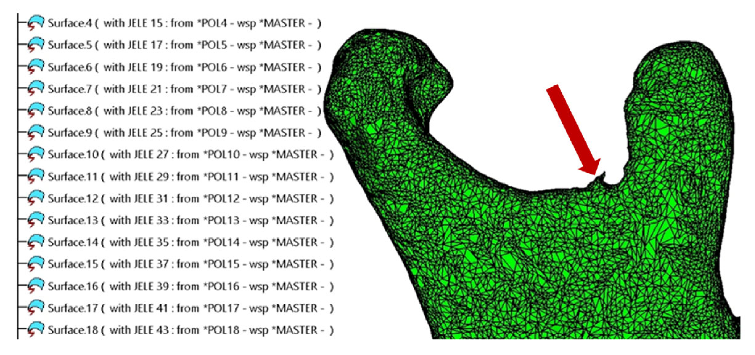
Figure 2.
Example of the mandibular surface: a. rough surface; b. smoothed surface.
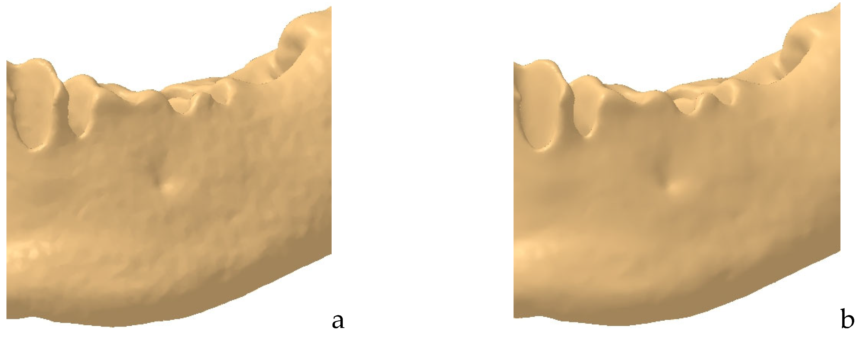
Figure 3.
Comparison between the initial surface and the final surface obtained using the Automatic Surface tool.
Figure 3.
Comparison between the initial surface and the final surface obtained using the Automatic Surface tool.
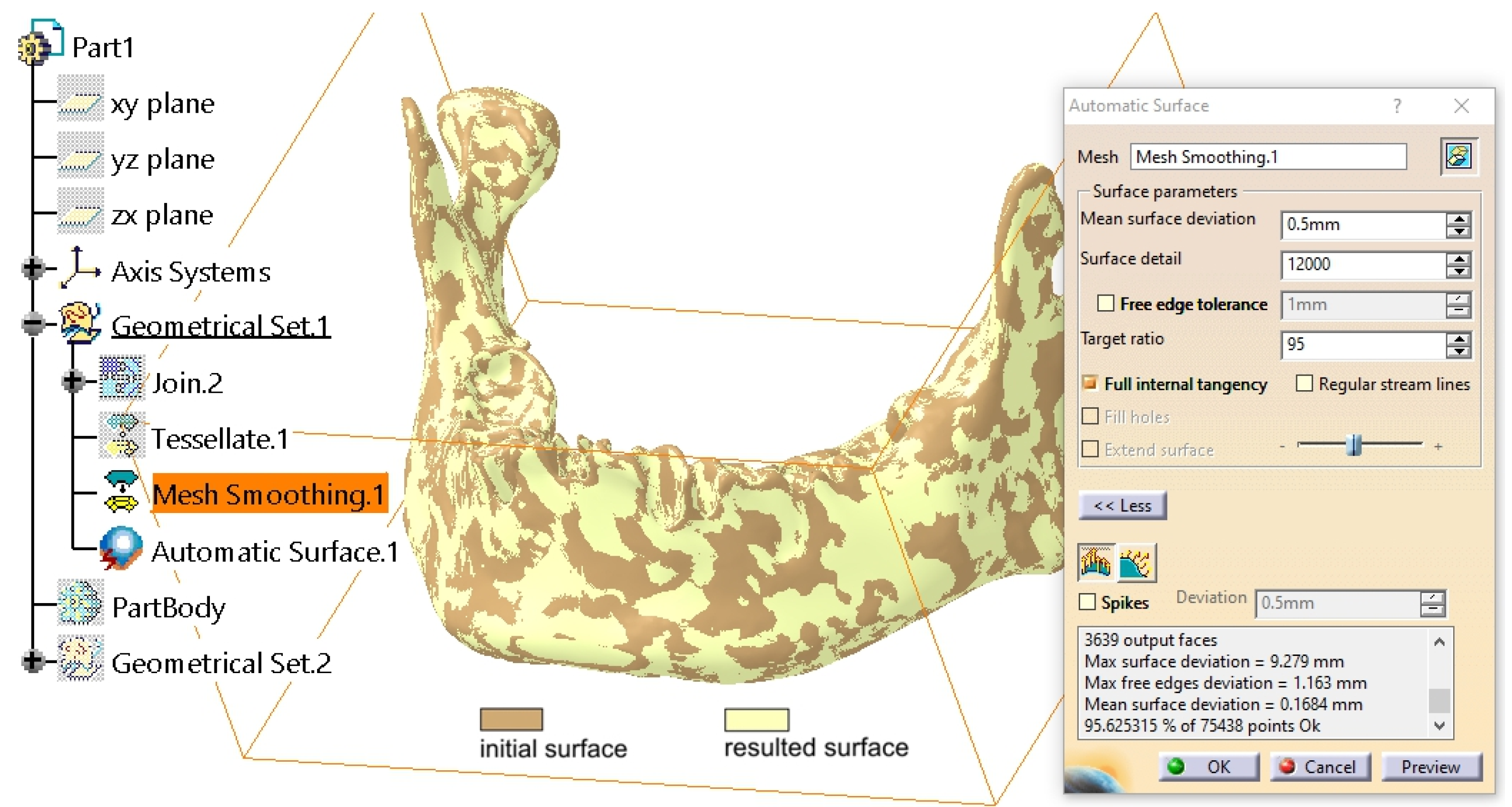
Figure 4.
Drawing the support wireframe lines and circles.
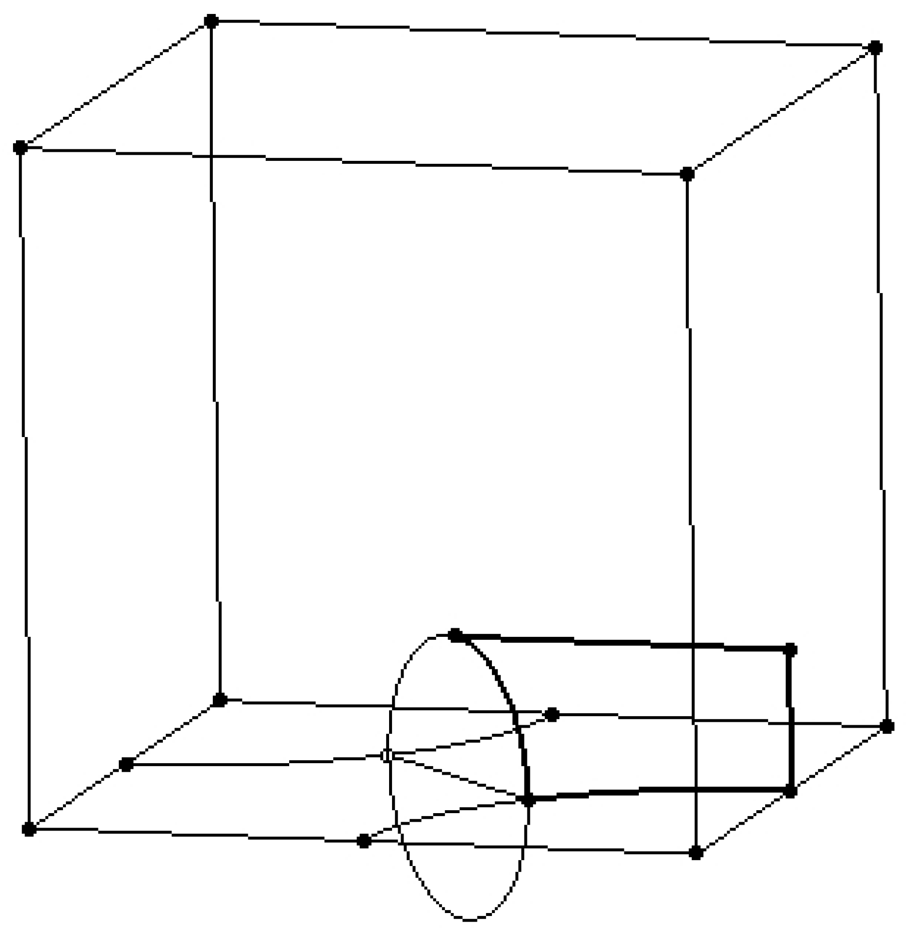
Figure 5.
Creation of the support surfaces, of the initial multi-sections surface and of its symmetrical surface.
Figure 5.
Creation of the support surfaces, of the initial multi-sections surface and of its symmetrical surface.
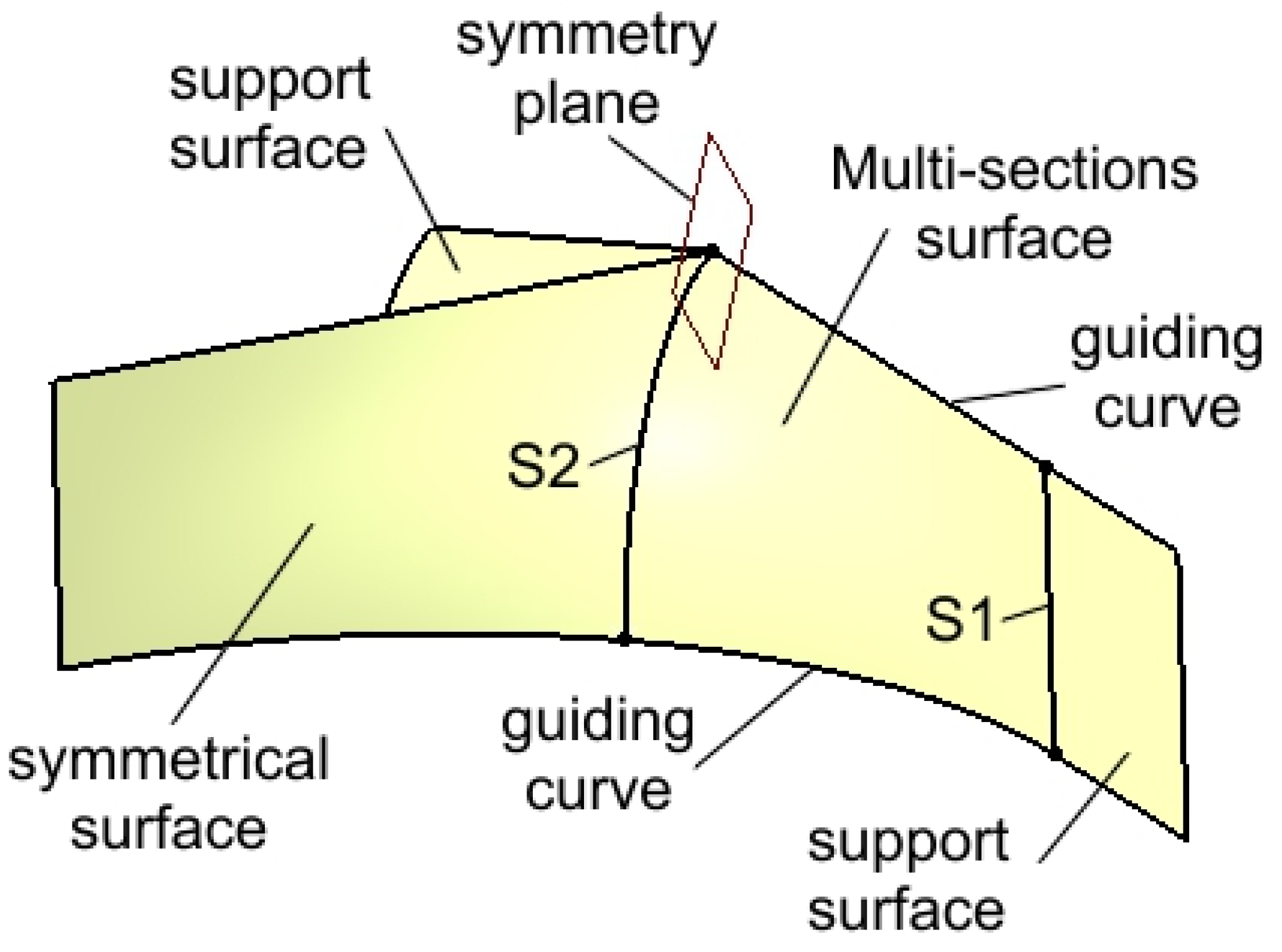
Figure 6.
Multiplied surfaces by rotation around edges and the Z axis.
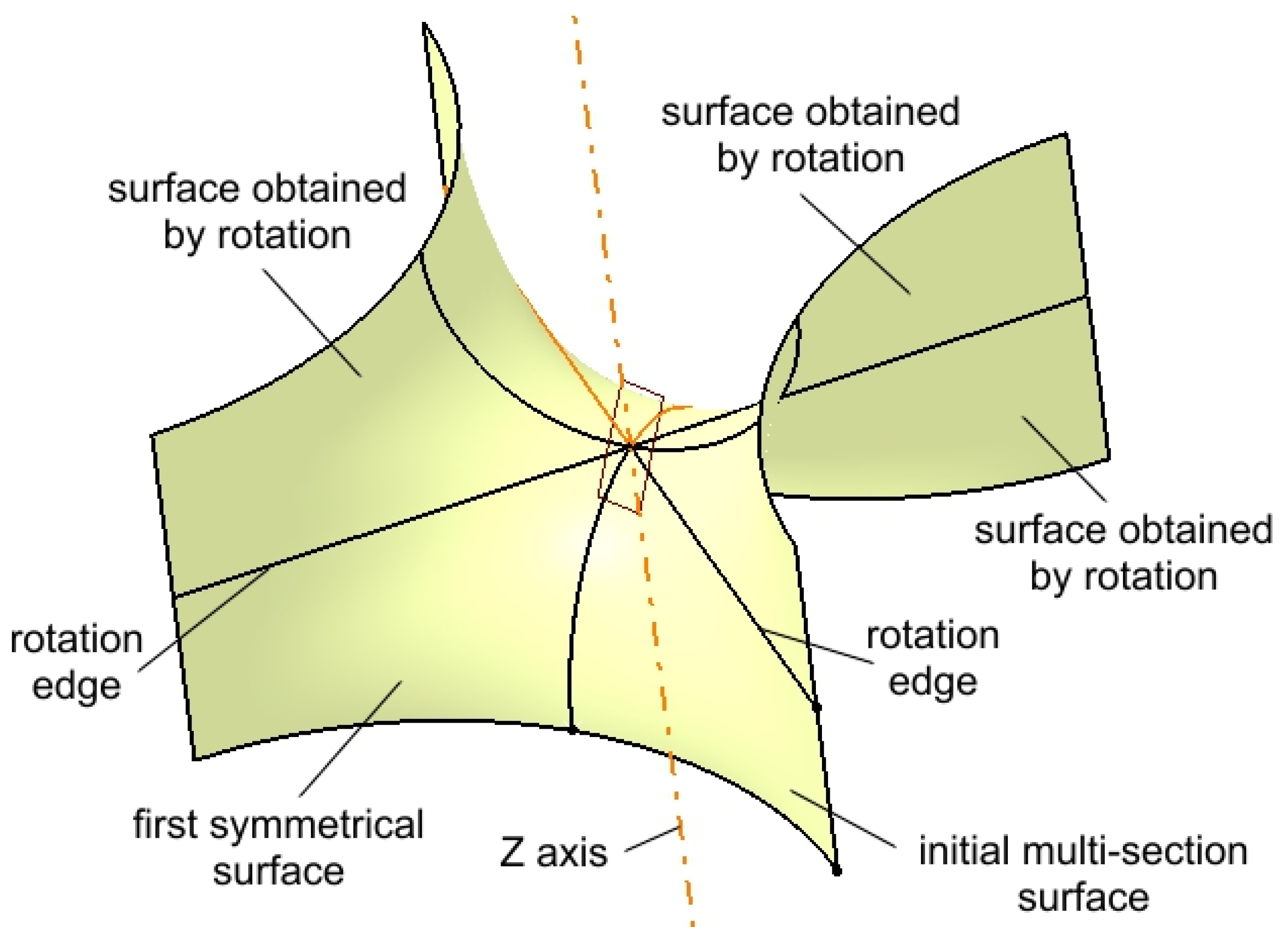
Figure 7.
Multiplied surfaces by symmetry about a horizontal plane to create the main surface.
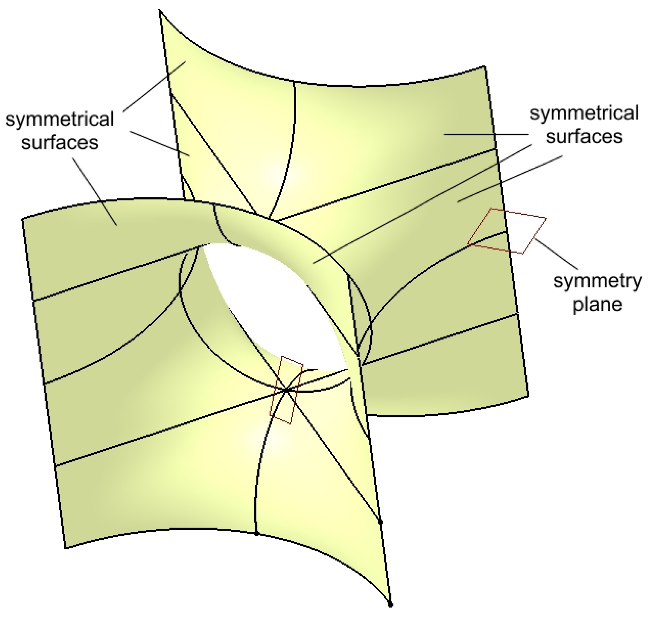
Figure 8.
The surface structure.
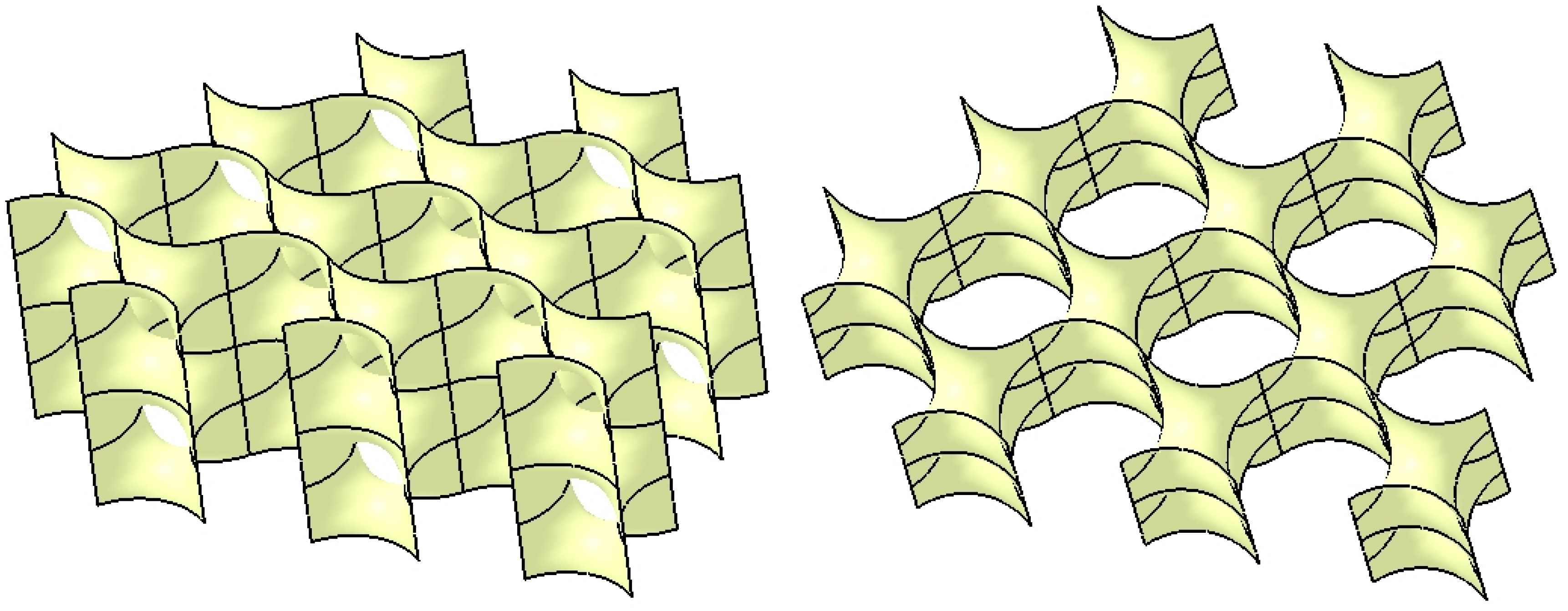
Figure 9.
The Scherk-type hollow lattice structure.
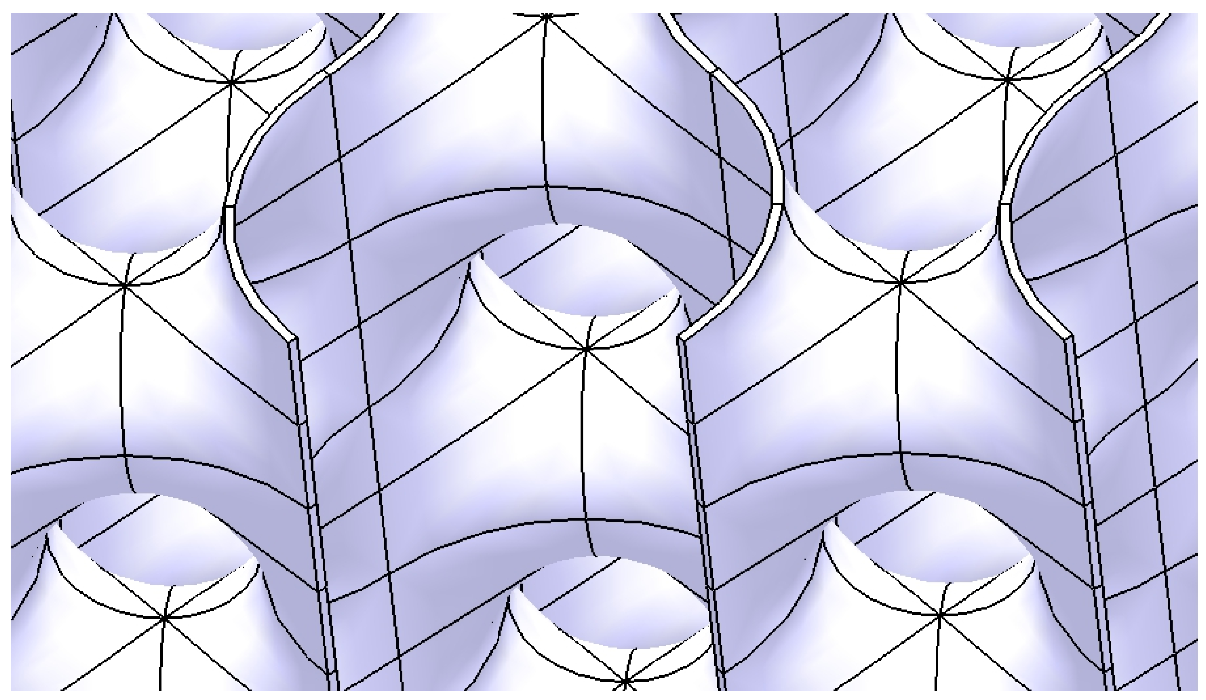
Figure 10.
Intermediary shape of the reconstruction structure with and without the trimming surface.
Figure 10.
Intermediary shape of the reconstruction structure with and without the trimming surface.
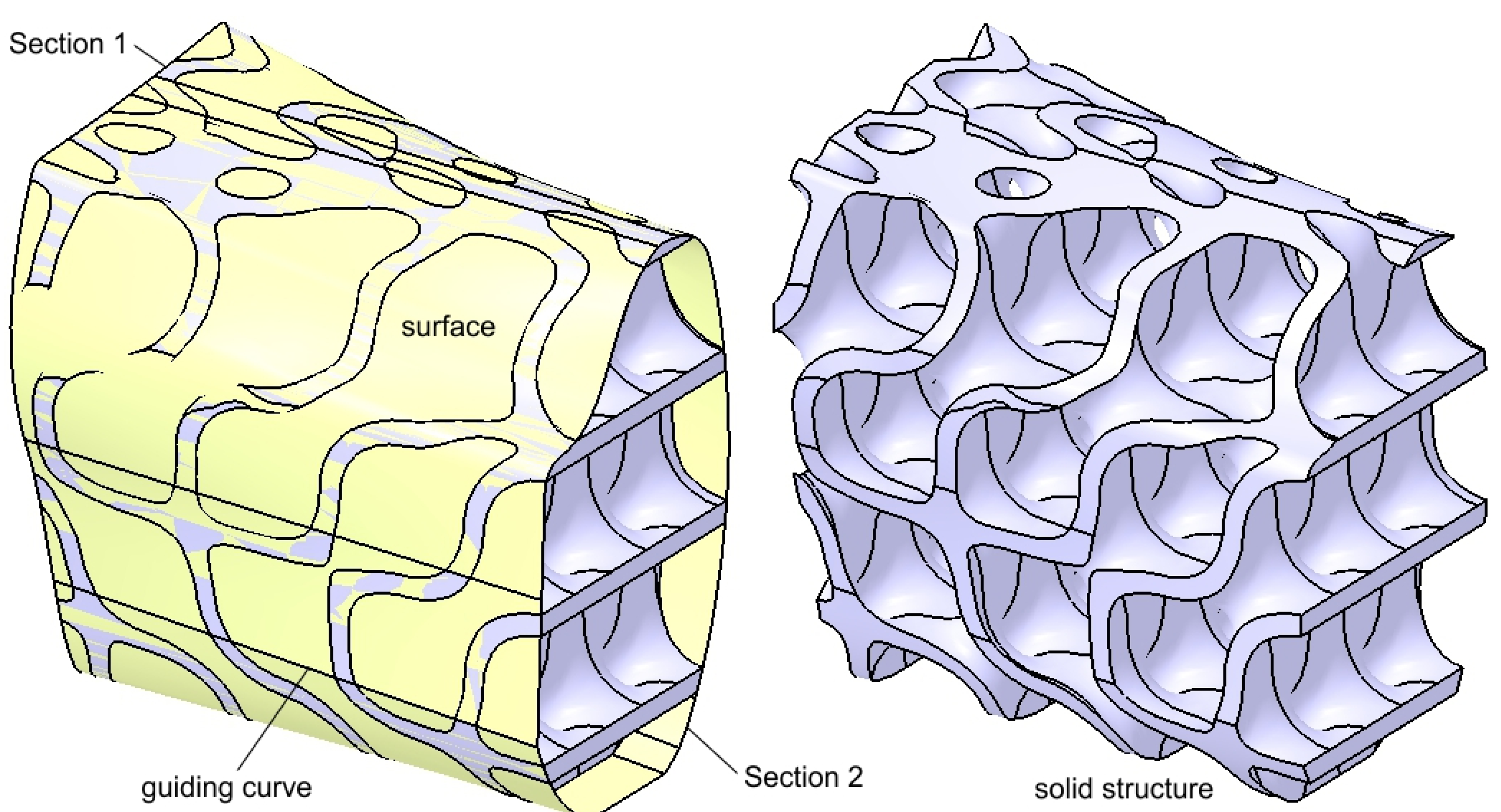
Figure 11.
The structure's shape after adding complementary surfaces to prevent abrasive contact with the mandibular bone and perimandibular soft tissues.
Figure 11.
The structure's shape after adding complementary surfaces to prevent abrasive contact with the mandibular bone and perimandibular soft tissues.
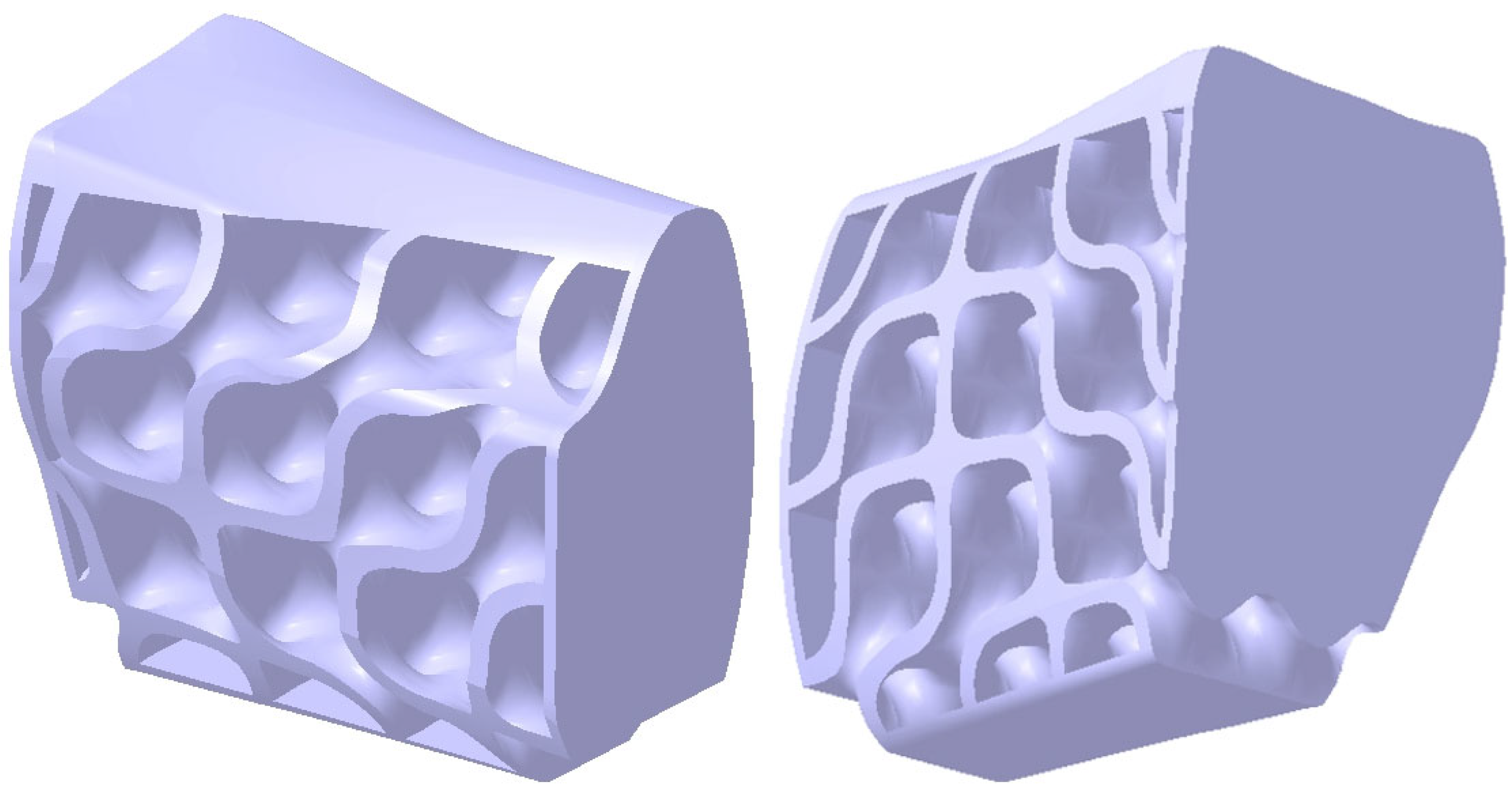
Figure 12.
Two fixing plates have been added to the structure.
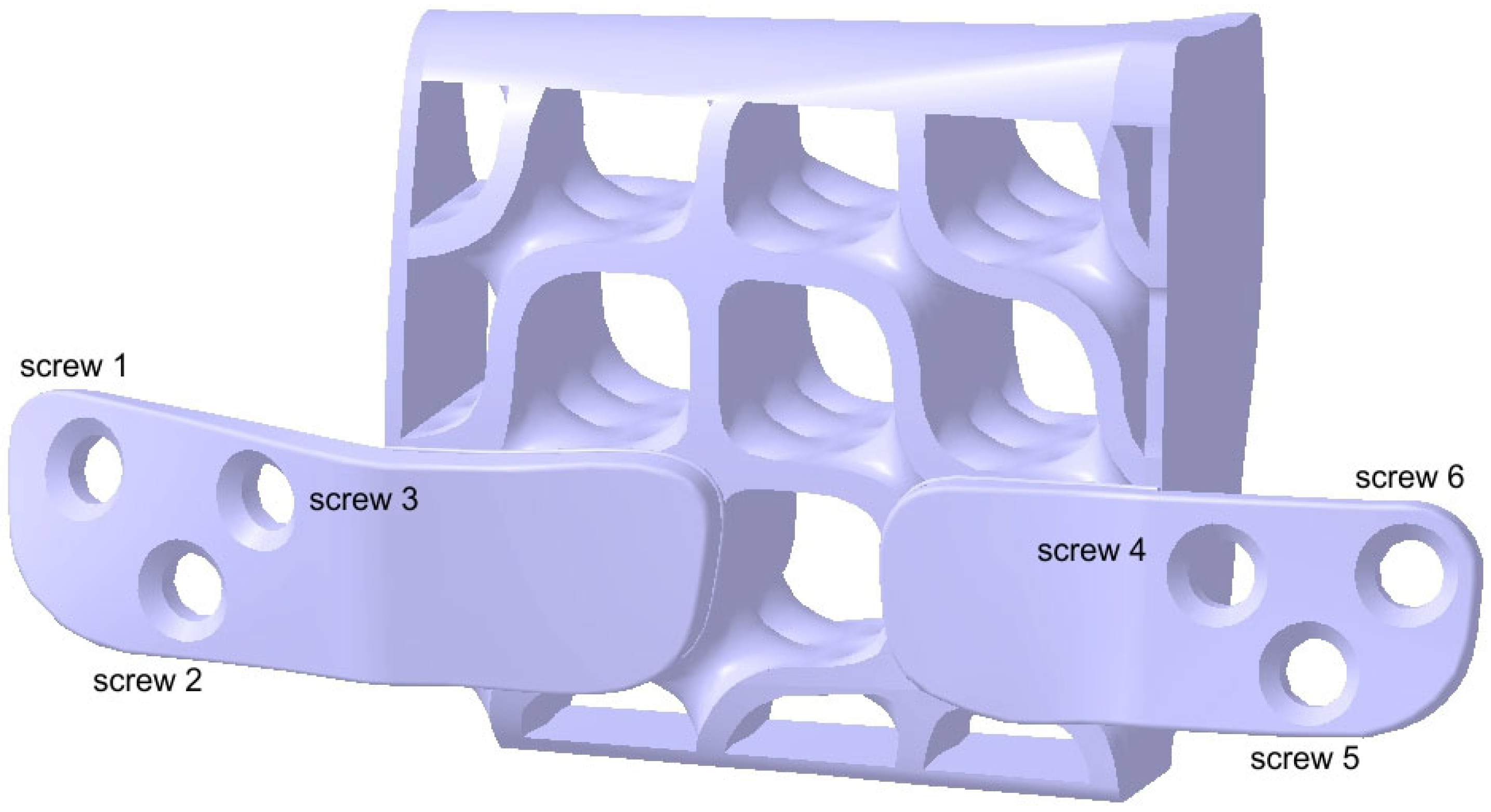
Figure 13.
The final shape of the reconstruction part is secured to the mandibular fragments using six screws (three on each side), ensuring structural continuity of the mandible.
Figure 13.
The final shape of the reconstruction part is secured to the mandibular fragments using six screws (three on each side), ensuring structural continuity of the mandible.
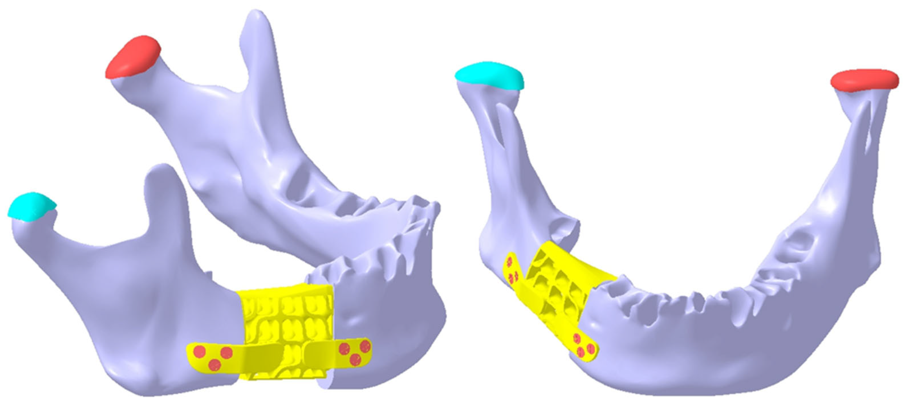
Figure 14.
The reconstruction part is secured to the remaining mandibular fragments using six screws, whose axes are neither parallel nor coplanar.
Figure 14.
The reconstruction part is secured to the remaining mandibular fragments using six screws, whose axes are neither parallel nor coplanar.
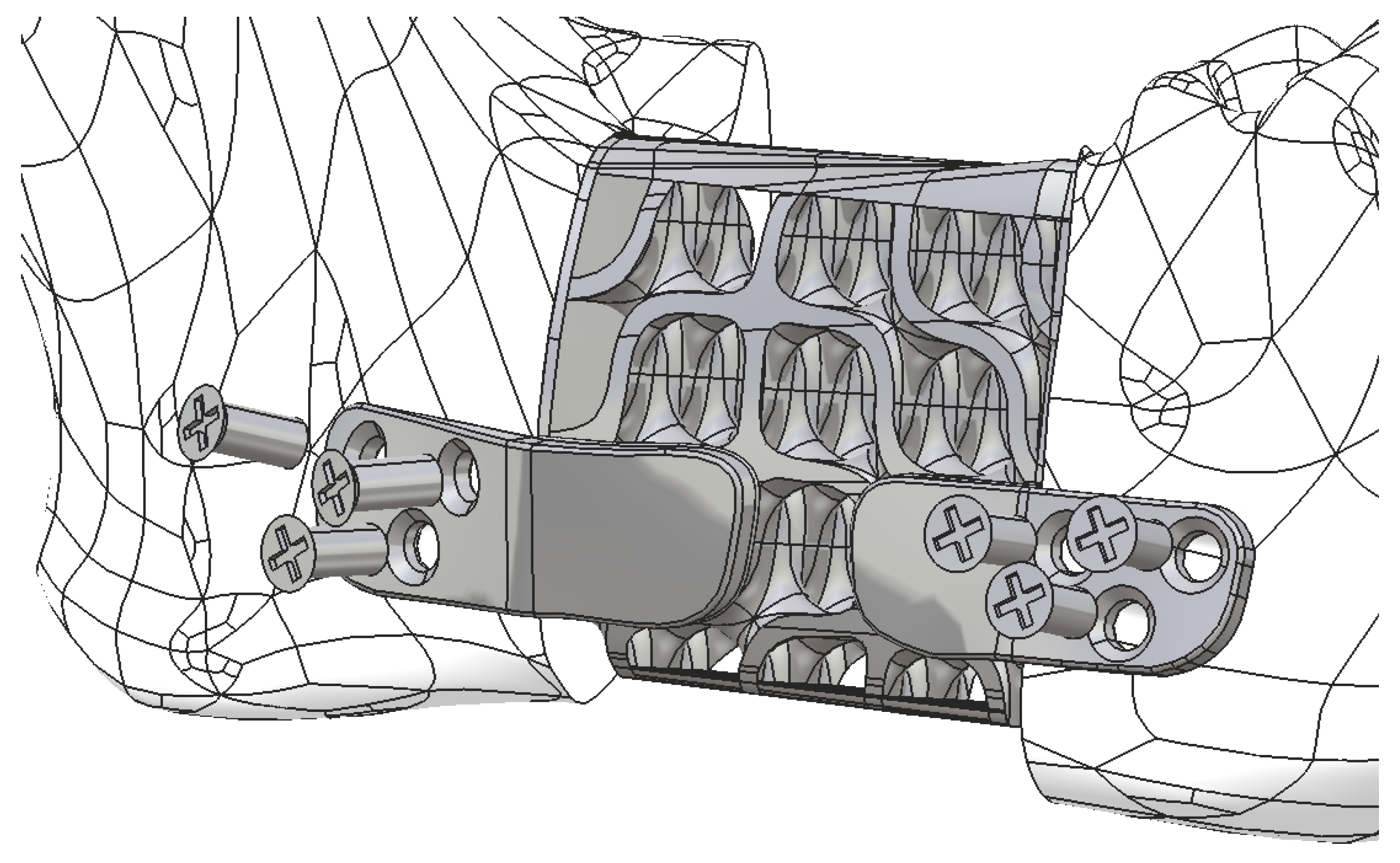
Figure 15.
Establishing a physical connection between the mandible, fixing plate, and screw.
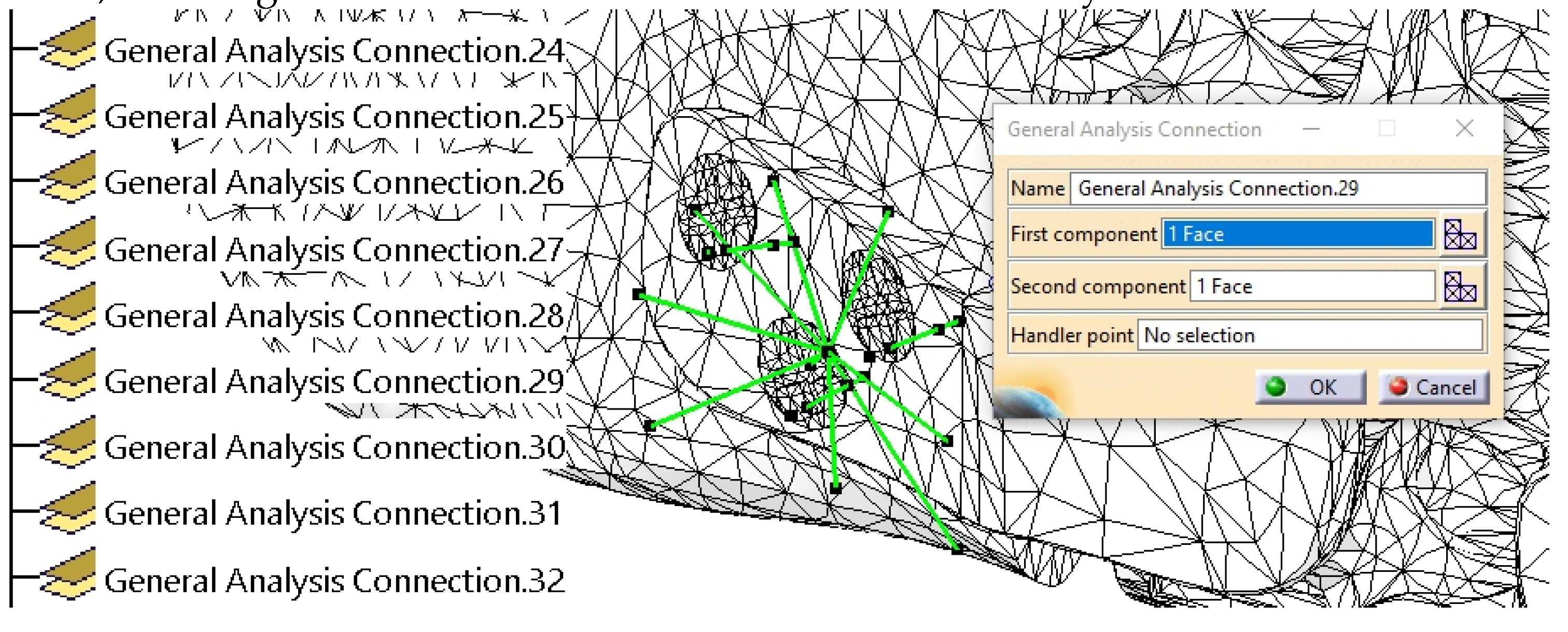
Figure 16.
Graphical representation of the applied forces on the mandible.
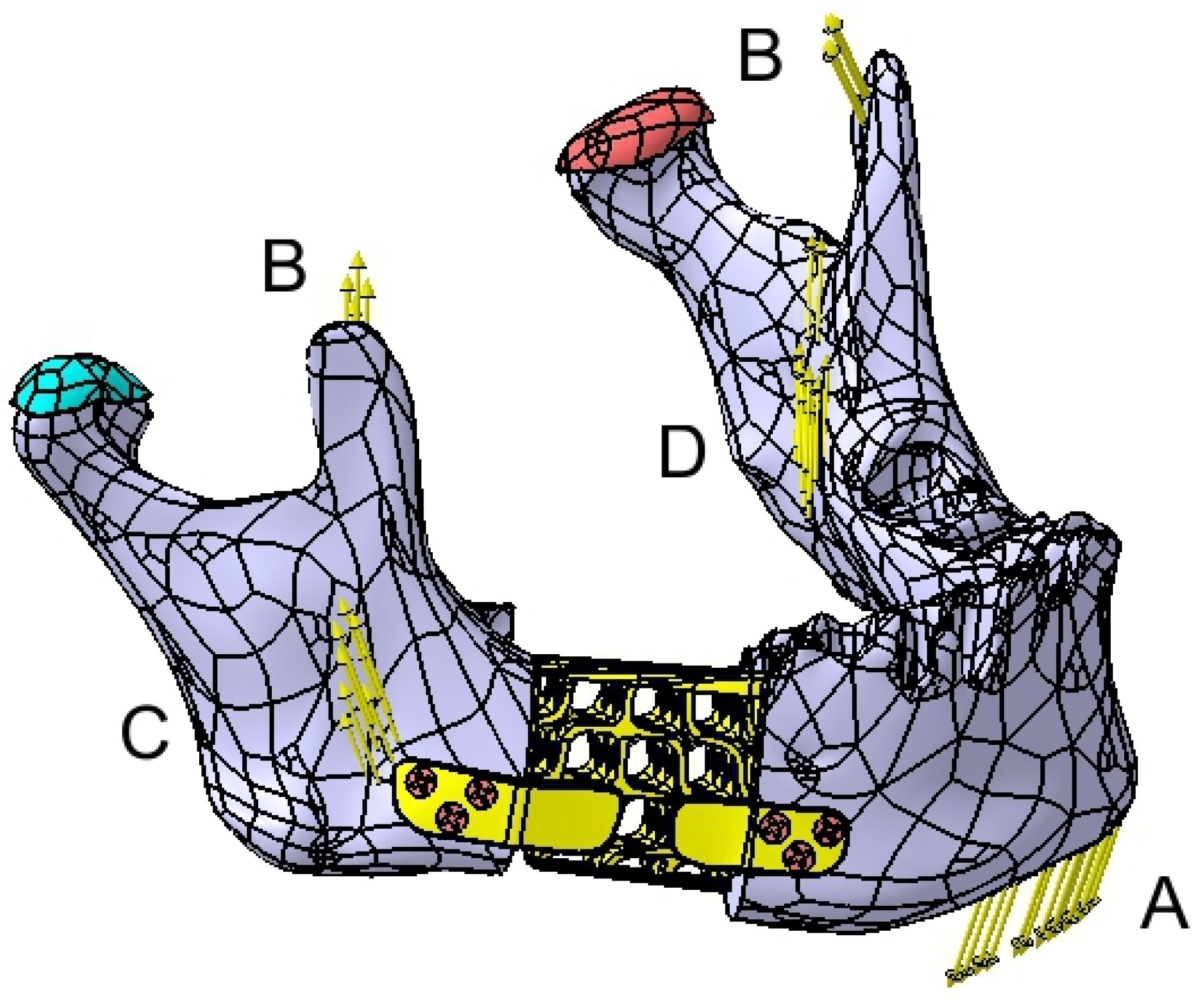
Figure 17.
Stress distribution within the reconstruction part with fixing plates.
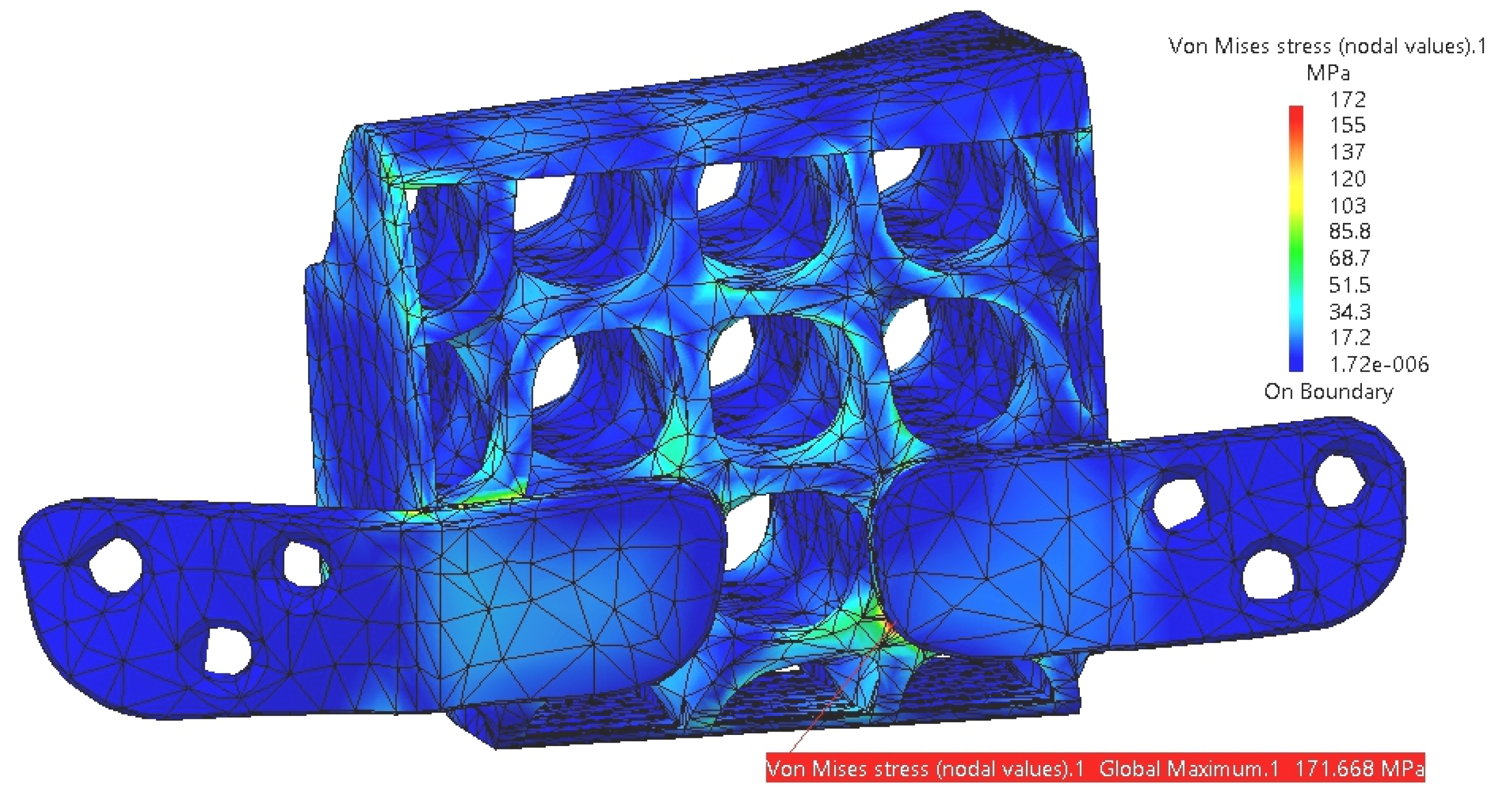
Figure 18.
Stress distribution on the mandible.
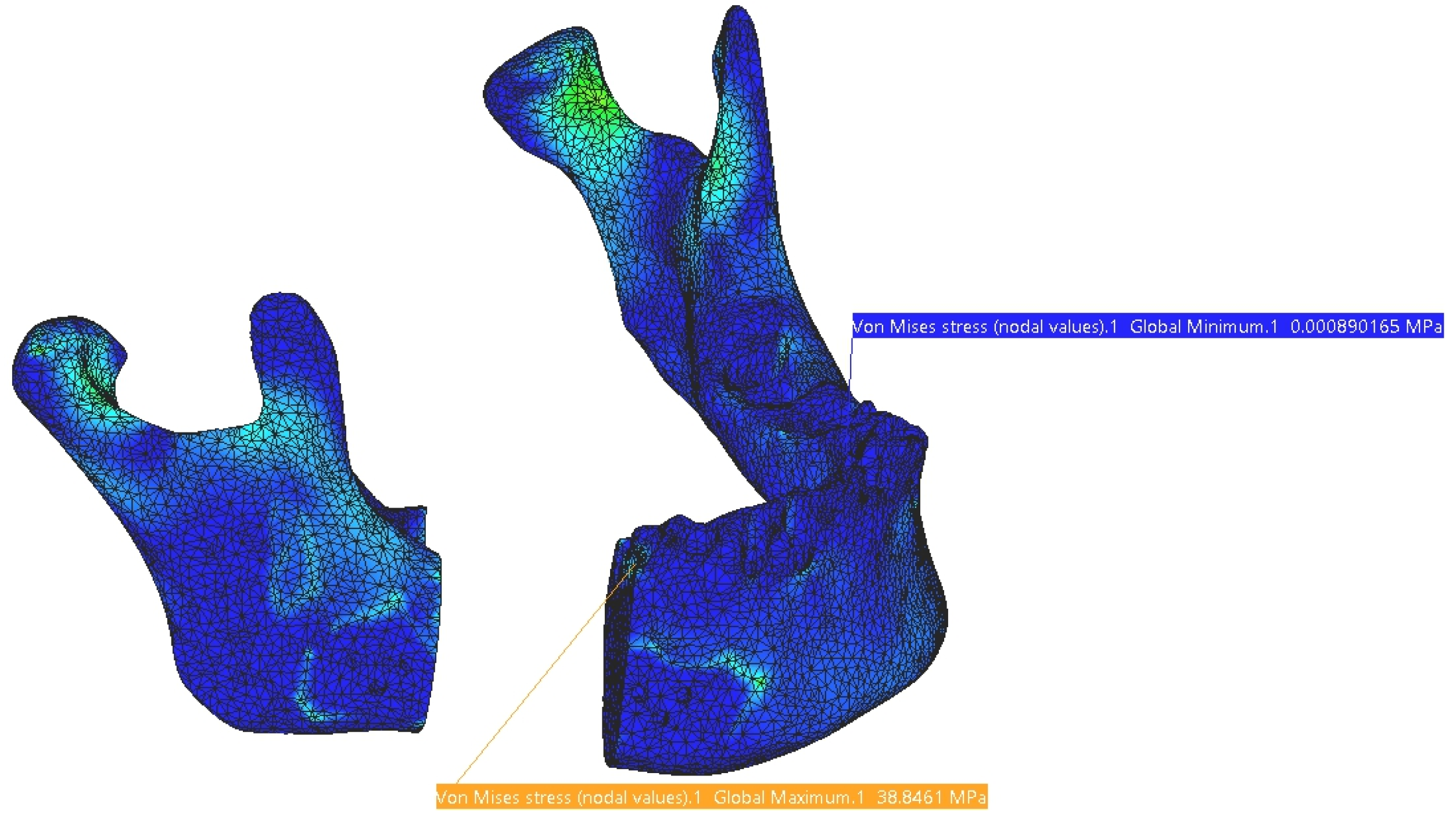
Figure 19.
Stress distribution on the reconstruction and mandible using the stress scale applied to the mandible.
Figure 19.
Stress distribution on the reconstruction and mandible using the stress scale applied to the mandible.
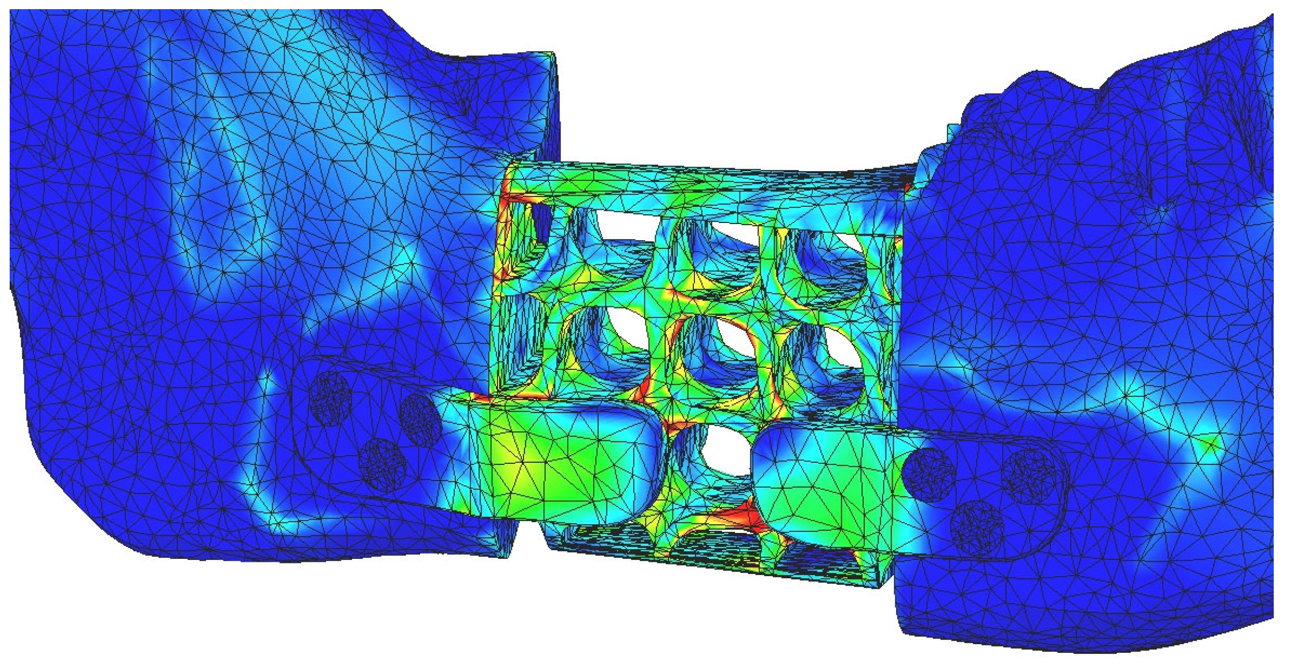
Figure 20.
Areas with maximum displacements.
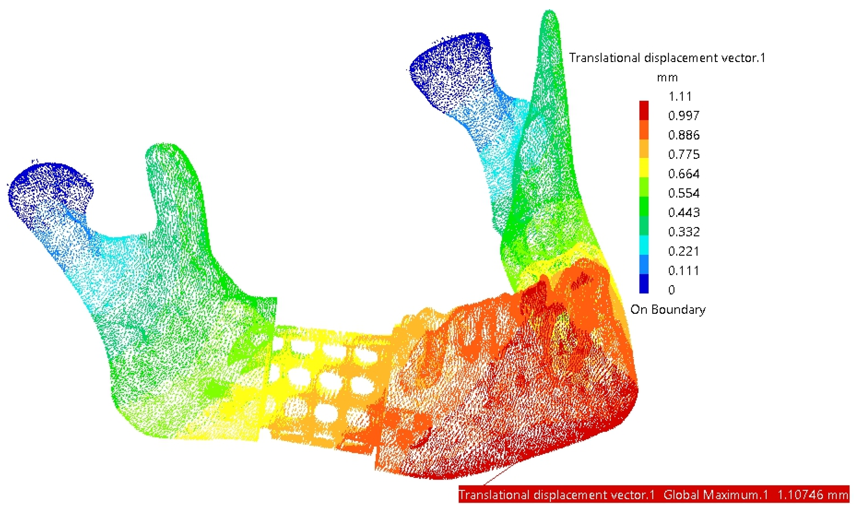

Table 1.
Key characteristics of the assembly components [23].
Table 1.
Key characteristics of the assembly components [23].
| Component | Finite element size, mm | Absolute sag, mm | Finite element type | Material |
| Mandible | 1.5 | 0.8 | Parabolic | Bone |
| Reconstruction part with fixing plates | 1.8 | 1 | Parabolic | Ti-Grade-4 (TI75A) or PEEK |
| TMJ disks | 1.2 | 0.3 | Parabolic | Cartilage |
| Screws | 0.5 | 0.2 | Linear | Ti-Grade-4 (TI75A) |
TMJ = temporomandibular joint; absolute sag = the maximum distance between the original surface and the mesh approximation.
Table 2.
Overview of the maximum stresses and displacements observed within the assembly mandible – titanium reconstruction part.
Table 2.
Overview of the maximum stresses and displacements observed within the assembly mandible – titanium reconstruction part.
| Component | Von Mises Stress, MPa | Translational displacement vector, mm | Component | Von Mises Stress, MPa | Translational displacement vector, mm |
|---|---|---|---|---|---|
| Test 1. Forces: A: 30N, B: 12N, C: 40N, D: 30N | |||||
| Mandible | 20.5 | 0.942 | Reconstruction | 65 | 0.852 |
| TMJ 1 | 2.53 | 0.093 | Screw 4 | 2.85×10⁻⁸ | - |
| TMJ 2 | 2.13 | 0.072 | Screw 5 | 1.74×10⁻⁸ | - |
| Test 2. Forces: A: 45N, B: 20N, C: 50N, D: 45N | |||||
| Mandible | 26.5 | 0.911 | Reconstruction | 102 | 0.828 |
| TMJ 1 | 3.06 | 0.105 | Screw 4 | 4.55×10⁻⁸ | - |
| TMJ 2 | 2.28 | 0.08 | Screw 5 | 5.18×10⁻⁸ | - |
| Test 3. Forces: A: 55N, B: 30N, C: 60N, D: 55N | |||||
| Mandible | 37.3 | 1.51 | Reconstruction | 123 | 1.37 |
| TMJ 1 | 4.27 | 0.155 | Screw 4 | 1.15×10⁻⁷ | - |
| TMJ 2 | 3.51 | 0.12 | Screw 5 | 1.05×10⁻⁷ | - |
| Test 4. Forces: A: 65N, B: 35N, C: 65N, D: 60N | |||||
| Mandible | 38.8 | 1.11 | Reconstruction | 149 | 1.01 |
| TMJ 1 | 4.03 | 0.137 | Screw 4 | 9.12×10⁻⁸ | - |
| TMJ 2 | 2.91 | 0.103 | Screw 5 | 1.09×10⁻⁷ | - |
| Test 5. Forces: A: 75N, B: 50N, C: 70N, D: 65N | |||||
| Mandible | 49.5 | 1.56 | Reconstruction | 172 | 1.41 |
| TMJ 1 | 4.9 | 0.174 | Screw 4 | 9.12×10⁻⁸ | - |
| TMJ 2 | 3.86 | 0.133 | Screw 5 | 1.09×10⁻⁷ | - |
TMJ 1 = right temporo-mandibular joint (condyle-disc construct), on the resected site; TMJ 2 = left temporo-mandibular joint (condyle-disc construct); Screws – numbered according to Figure 12.
Table 3.
Overview of the maximum stresses and displacements observed within the assembly mandible – PEEK reconstruction part.
Table 3.
Overview of the maximum stresses and displacements observed within the assembly mandible – PEEK reconstruction part.
| Component | Von Mises Stress, MPa | Translational displacement vector, mm | Component | Von Mises Stress, MPa | Translational displacement vector, mm |
|---|---|---|---|---|---|
| Test 1. Forces: A: 30N, B: 12N, C: 40N, D: 30N | |||||
| Mandible | 12.9 | 0.915 | Reconstruction | 47.7 | 0.85 |
| TMJ 1 | 2.85 | 0.097 | Screw 4 | 1.11×10⁻⁷ | - |
| TMJ 2 | 1.98 | 0.069 | Screw 5 | 9.87×10⁻⁸ | - |
| Test 2. Forces: A: 45N, B: 20N, C: 50N, D: 45N | |||||
| Mandible | 15.4 | 0.867 | Reconstruction | 73.1 | 0.822 |
| TMJ 1 | 3.57 | 0.12 | Screw 4 | 5.73×10⁻⁸ | - |
| TMJ 2 | 2.07 | 0.075 | Screw 5 | 6.27×10⁻⁸ | - |
| Test 3. Forces: A: 55N, B: 30N, C: 60N, D: 55N | |||||
| Mandible | 21.3 | 1.46 | Reconstruction | 90.5 | 1.37 |
| TMJ 1 | 4.93 | 0.166 | Screw 4 | 1.24×10⁻⁷ | - |
| TMJ 2 | 3.24 | 0.113 | Screw 5 | 8.99×10⁻⁸ | - |
| Test 4. Forces: A: 65N, B: 35N, C: 65N, D: 60N | |||||
| Mandible | 19.3 | 1.04 | Reconstruction | 108 | 0.993 |
| TMJ 1 | 4.88 | 0.163 | Screw 4 | 7.92×10⁻⁸ | - |
| TMJ 2 | 2.59 | 0.095 | Screw 5 | 7.17×10⁻⁸ | - |
| Test 5. Forces: A: 75N, B: 50N, C: 70N, D: 65N | |||||
| Mandible | 22.8 | 1.47 | Reconstruction | 127 | 1.39 |
| TMJ 1 | 6.03 | 0.201 | Screw 4 | 4.41×10⁻⁸ | - |
| TMJ 2 | 3.47 | 0.123 | Screw 5 | 4.57×10⁻⁸ | - |
TMJ 1 = right temporo-mandibular joint (condyle-disc construct), on the resected site; TMJ 2 = left temporo-mandibular joint (condyle-disc construct); Screws – numbered according to Figure 12.
Table 4.
Overview of the comparative properties of titanium and PEEK reconstructions.
| Component | Material | Density, kg/m3 | Yield Strength, MPa | Volume, mm3 | Mass, g |
|---|---|---|---|---|---|
| Reconstruction part without screws | Ti-Grade-4 | 4500 | 550 | 2206.51 | 9.929 |
| Reconstruction part without screws | PEEK | 1300 | 100 | 2206.51 | 2.868 |
| Screw | Ti-Grade-4 | 4500 | 550 | 14.83 | 0.07 |
| Reconstruction part with six screws | Ti-Grade-4 | 4500 | 550 | 2295.49 | 10.33 |
| Reconstruction part with six screws | PEEK + Ti-Grade-4 | 13004500 | 100550 | 2295.49 | 3.269 |
Ti-Grade-4 (TI75A) = titanium; PEEK = Polyetheretherketone.
Disclaimer/Publisher’s Note: The statements, opinions and data contained in all publications are solely those of the individual author(s) and contributor(s) and not of MDPI and/or the editor(s). MDPI and/or the editor(s) disclaim responsibility for any injury to people or property resulting from any ideas, methods, instructions or products referred to in the content. |
© 2025 by the authors. Licensee MDPI, Basel, Switzerland. This article is an open access article distributed under the terms and conditions of the Creative Commons Attribution (CC BY) license (http://creativecommons.org/licenses/by/4.0/).
Copyright: This open access article is published under a Creative Commons CC BY 4.0 license, which permit the free download, distribution, and reuse, provided that the author and preprint are cited in any reuse.


