Submitted:
07 March 2025
Posted:
07 March 2025
You are already at the latest version
Abstract
Cable-driven actuators (CDAs) are extensively used in the rehabilitation field because of advantages such as low moment of inertia, fast movement response, and intrinsic flexibility. However, velocity-induced disturbances pose challenges to accurate force control during dynamic movements. Several strategies for force control have been investigated in the literature, but repetitive time-consuming tests are often required. The aim of this study was to develop a force feedback controller and a speed feedforward compensator for a CDA utilising an experiment-based approach. The CDA comprised a motor, a cable drum, and a force sensor. The plant transfer function was estimated through an open-loop test. A PI force feedback controller was developed and evaluated in a static test. Subsequently, a dynamic test with a constant reference force was conducted, during which the cable was pulled to move at different speeds. The relationship between the motor speed and the cable force was determined, which facilitated further development of a speed feedforward compensator. Additionally, the system dynamics were simulated in MATLAB/Simulink. The static test showed that the PI force controller produced a mean force control error of 4.7 N, which was deemed very good force tracking accuracy. The model simulated the dynamic of CDA with the force output very similar to the experiment (RMSE error of 4.0 N). During the dynamic test, the PI force controller alone produced a force control error of 9.0 N. The additional speed feedforward compensator further reduced this error to 5.6 N. The combined force feedback controller and the speed feedforward compensator produced a satisfactory degree of accuracy during dynamic tests of the CDA at variable speeds. The experiment-based design of the force control strategy for the CDA shows potential to be a control approach for general CDAs, which establishes the foundation for precise movement control as required in cable-driven rehabilitation robotic systems. Future work will be integration of the speed compensator into better feedback algorithms for more accurate force control.
Keywords:
Force control
; speed compensation
; disturbance rejection
; cable-driven actuator
; dynamic simulation
; rehabilitation robotics
1. Introduction
As a promising auxiliary paradigm for the physiotherapists, rehabilitation robotic systems are employed to implement various neuromuscular therapies [1]. Among different robotic structures, cable-driven robotic systems are frequently used to provide 3D natural movement guidance. Cable-driven actuators (CDAs) offer advantages such as low moment of inertia, fast movement response, and intrinsic flexibility [2,3]. Examples of CDAs for upper limb rehabilitation include the 3D shoulder support CAREX [4], the Parallel Cable-Driven Upper Limb Rehabilitation Robot [5], and the r3-system, which is a reconfigurable rope robot for rowing simulation [6] and tennis play [7]. Representative utilisations of CDAs in pelvic and trunk support have the Active Tethered Pelvic Assist Device (A-TPAD) [8], the Trunk Support Trainer (TruST) [9] and the device for body segment reloading and relieving [2,10]. Typical applications of CDAs in lower-limb rehabilitation include the Cable-driven Active Leg Exoskeleton C-ALEX [11] and the system for gait restoration [3]. The intrinsic flexibility of CDAs enables these robotic systems to offer natural guidance required during different phases of rehabilitation.
In the development of cable-driven robotic systems, accurate force control is the basic requirement for the movement regulation. Control of cable-driven robotic systems typically involves two levels of controllers: high-level position controllers in the outer loop and low-level force controllers in the inner loop [8,10,11,12]. Accurate tracking of the target force within each cable is relatively straightforward in static situations, such as during isometric training. A PID controller [13] or a lead controller [14] can provide satisfactory results. However, cable-driven robotic systems are widely applied in dynamic movement training where the cable has to follow a specific movement trajectory. The movement induces kinetic changes, such as the target human-robot interaction force, the required torque for the drive components, and the nonlinear friction within the CDA [12]. These kinetic changes bring disturbances to dynamic control of force in the cable. Consequently, motion-induced disturbances make it challenging to achieve accurate dynamic force control. Both experimental and theoretical strategies have been explored in the literature.
Force control is often implemented using a conventional approach, where the control parameters are determined through experimental testing. In the development of Myoshirt [12], which is a cable-driven exosuit that supports the shoulder joint during functional arm elevation, a PI force controller with friction compensation was implemented. The r3-system employed a force control strategy that included a simple proportional controller, a friction compensator, and an additional feedforward component [7]. C-ALEX [11] and A-TPAD [8] used a similar control strategy, which consists of three parts: a PID feedback controller, a feedforward term using the motor constant, and a friction compensator. These studies primarily relied on experiments to develop their control strategies without investigating the system transfer function. However, experimental-based friction compensation requires repetitive tests to find the accurate friction-speed relationship.
In parallel to the experimental approach, theoretical analysis of system dynamics has also been performed in the development of force control strategies. The research group led by Zhang et al. developed various cable-driven robotic systems [2,3,5]. By modelling the cable in each CDA as a spring-damper mechanism, they deduced the transfer function from motor torque to force output as a third-order system. The force control strategy is composed of a second-order phase-lead feedback element, apart from an integral element and a feedforward element of a constant gain. The disturbance caused by motor speed was also analysed. Based on the structure invariance principle, a compensator was designed as a third-order system. These algorithms produced good force control accuracy and were applied in the rehabilitation of upper [5], lower [3] limbs as well as general body reloading and unloading [2,10]. However, effective disturbance rejection depends upon an accurate model of the CDA. We previously developed a system with four CDAs to assist walking on the treadmill [14,15]. Based on a model with a spring-damper element for each CDA, we developed for each CDA a force-feedback lead controller and a velocity-feedforward lead compensator. The algorithms produced satisfactory force control accuracy, but design of both lead controllers also required an accurate dynamic model of the CDA. System identification of CDAs involves sophisticated estimation of many system parameters and a series of time-consuming dynamic tests for parameter validation.
An accurate control strategy for force regulation of the cable is a fundamental requirement for application of cable-driven robotic systems. These robotic systems often involve simultaneous interaction of multiple CDAs. The movement-induced disturbances can potentially cause vibrations when several CDAs are used in parallel to produce dynamic movement [16]. Therefore, it is desirable to develop a convenient and accurate force control strategy for each CDA, as preparation for higher-level position control of multiple CDAs. The aim of this work was to develop a force feedback controller and a speed feedforward compensator for a CDA using an experiment-based method. To test the control algorithms, the CDA was applied in dynamic arm training.
2. Methods
Using the System Identification Toolbox (The MathWorks, Inc., USA, Version 2024a), the dynamic model of the CDA was determined. The relationship between motor speed and force output was identified. The force control strategy was developed and simulated in MATLAB/Simulink. The control algorithms were implemented in TwinCAT3 (Beckhoff Automation GmbH & Co, Germany). The static and dynamic test results were compared with the simulated results in MATLAB/Simulink.
2.1. Mechanical Description
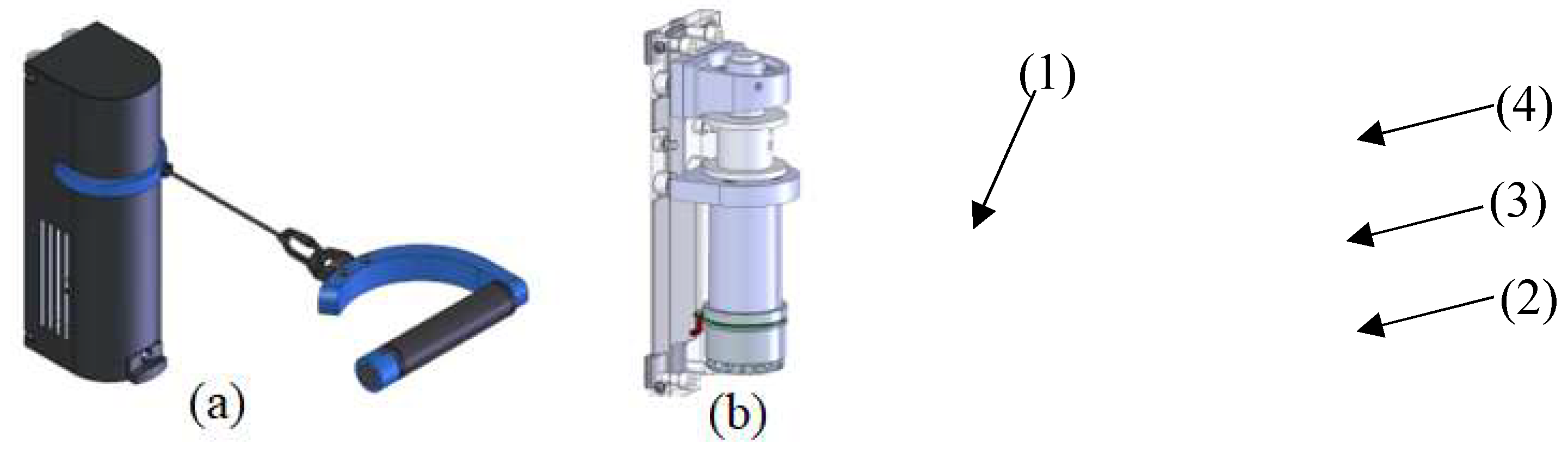
The CDA (Fig.1) consists of a motor (EC60, maxon motor, Switzerland), a gear (ratio of 49/4), a drum (diameter of 0.04 m), and a force sensor (maximal range of 500 N). Controlled by a servo controller (EPOS4 Compact 50/8 with EtherCAT interface, maxon motor, Switzerland), the CDA can theoretically produce a maximal pull force of about 250 N. The CDA was previously employed in arm training [13] and body weight support [17]. In the current study, the CDA was tested for arm training to evaluate the control algorithms developed in this work.
Figure 1.
The cable-driven actuator. (a) The device case with the handle (1) and (b) components inside the case: Motor (2), gearbox (3) and drum (4).
Figure 1.
The cable-driven actuator. (a) The device case with the handle (1) and (b) components inside the case: Motor (2), gearbox (3) and drum (4).
2.2. Force Control Strategy
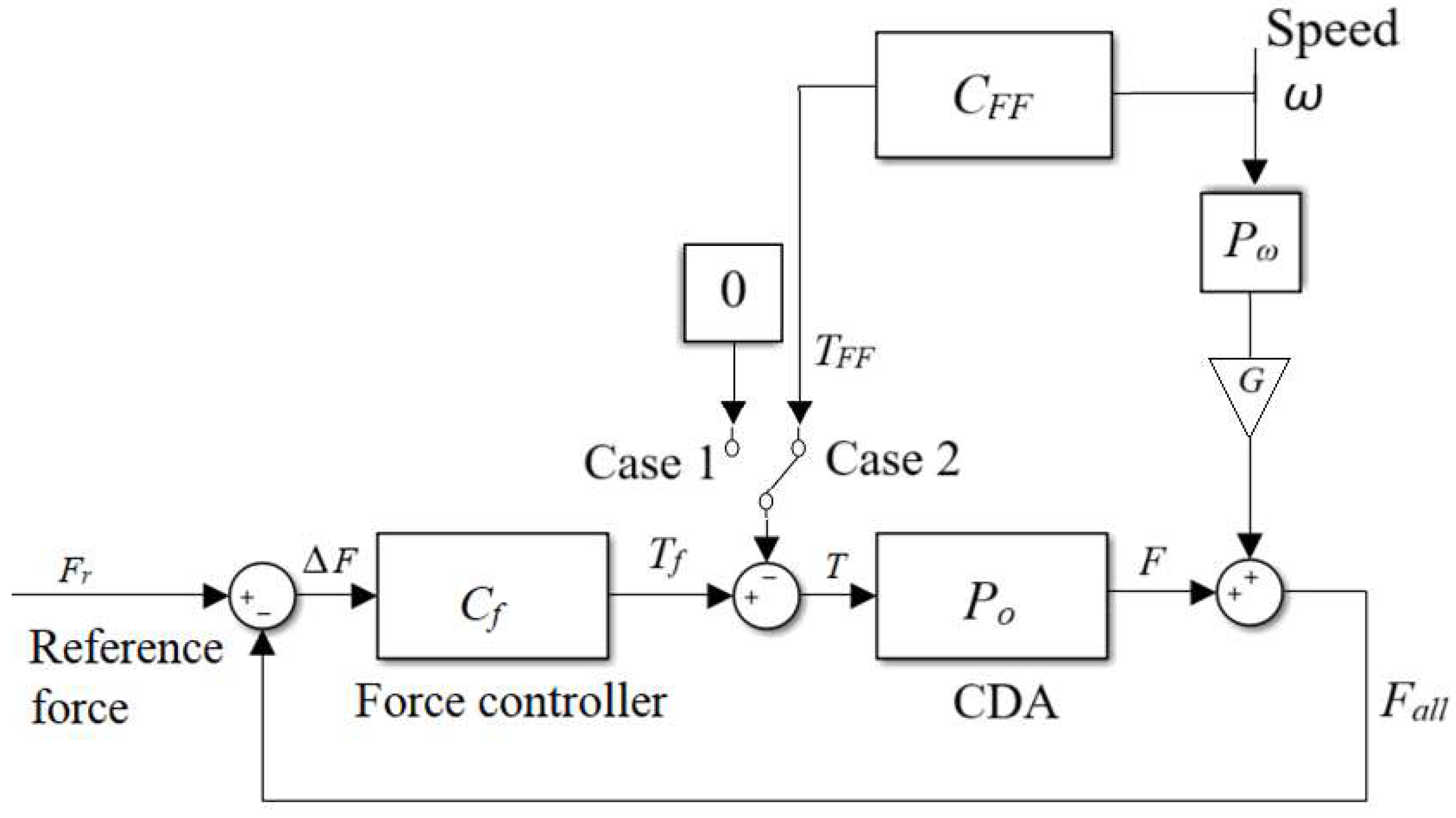
The control strategy included a force feedback control Cf (Case 1 in Fig. 2) for static isometric training and an additional speed feedforward compensator CFF (Case 2 in Fig. 2) for dynamic training. Development of the control strategy required dynamic analysis of the system, which was performed based on experimental data as described below.
Figure 2.
The control strategy.
The transfer function of the CDA Po, which shows the relationship between motor torque T and force output F on the cable, is simplified as a first-order structure:
where and are the gain and the time constant. An open-loop test was performed to determine the two parameters and . A series of square-wave torque were sent to the motor. A test person held the handle still to resist the force. The actual force measurement was recorded. Then the system transfer function Po was determined using the System Identification Toolbox.
In order to produce a user-defined profile of resistance training, a PI force controller Cf was implemented. The input to and output from Cf are ΔF (the difference between the reference force Fr and the all force Fall) and target torque Tf to CDA, respectively. The transfer function of Cf is:
where kpf and kif are the proportional and integral gains.
As explained in the introduction and also shown in the result section (Figs. 6-8), the force control accuracy was influenced by the motor speed. An additional speed compensator for force control during movement was designed as described below.
A repetitive test was performed in the PI-controlled CDA so as to find the relationship between motor speed and force control error. The PI controller was implemented to produce a reference resistive load of 100 N. The cable was manually moved by a test person to follow a sinusoidal position trajectory at different speeds, where a metronome was used to control the movement rhythm. The cable was pulled in synchronisation with the beat and then released with the subsequent beat. Thus, a metronome beat of 60 BPM corresponds to a sinusoidal movement at a frequency of 0.5 Hz. The relationship between the motor speed and the force output, Pω, was searched for using the System Identification Toolbox.
A gain G was introduced in Fig. 2 to compensate the attenuation effect of the control loop Cf on the disturbance. Using the closed-loop control theory, the transfer function of disturbance on the output, So, should be:
The Bode diagram of So shows that the disturbance input will appear in the force output with some change in the amplitude Gd with a phase shift. The gain G as shown in Fig. 2 should be:
After the disturbance Pω was determined, a feedforward compensator was obtained as:
The effect of the feedforward strategy was compared by running the PI controller Cf only (Case 1 in Fig. 2) and the PI controller Cf plus feedforward compensator CFF (Case 2 in Fig. 2). In both cases, the cable of the CDA was pulled and released at the metronome beats of 60, 50, and 40 BPM, respectively.
2.3. Simulation of the Force Control Strategy
To verify the plant transfer function Po and to validate the control algorithms, a dynamic model was developed in MATLAB/Simulink. The CDA was modelled using the experimental-developed transfer function Po (Eq. 1). The control strategies as shown in Eqs. 2-5 were modelled. To evaluate the model accuracy, the root-mean-square error (RMSE) of the force output RMSE_Fexp_sim and the torque RMSE_Texp_sim are calculated on an evaluation interval from to to t1 as follows:
where N is the number of data points in the interval to to t1. To evaluate the force tracking accuracy from the control strategies, RMSE_Fexp_r, which is the RMSE between the experimental force output Fall_exp and the reference force Fr, is calculated as follows:
Similarly, the RMSE between the simulated force output Fall_sim and the reference force Fr is calculated using:
For the force test, we defined an error smaller than 5%, i.e., an RMSE smaller than 5 N for a reference force of 100 N, as a very good force control strategy to satisfy general arm muscle training. A strategy that produces an error between 5 N and 7.5 N is deemed as a satisfactory strategy. The same standard was used to evaluate model simulation: an RMSE_Fexp_sim smaller than 5 N or between 5 N and 7.5 N is considered as a very good or satisfactory simulation.
3. Results
In the open-loop test, 25% and 50% of the maximal torque produced a mean force of 72 N and 125 N (Fig. 3), respectively. Although the test person tried to keep the handle static by resisting the square reference force, the cable still moved slightly (Fig. 3c). The System Identification Toolbox yielded the system parameters = 2 and = 0.03. The goodness of fit is 57%.
The gains of PI feedback controller were tuned by experience and were evaluated by performing a static test, where different force profiles were set as the reference. Using kpf = 15, and kif = 1, the CDA produced good static force control with an RMSE_Fexp_r of 4.9 N for the square-wave reference force (Fig. 4) and 4.5 N in the sinusoidal reference force (Fig. 5). The simulated control signal, which is the torque to the motor, presented a similar curve as the experimental control signal (RMSE_Texp_sim of 5.8% of the maximal torque in Fig. 4(b) and 6.2% of the maximal torque in Fig. 5(b)). The simulated force output was similar to the experimental output (RMSE_Fexp_sim of 3.1 N in Fig. 4(a) and 4.8 N in Fig. 5(a)). This means that the model produced very good simulation results. Both figures prove that the plant parameters were acceptable, and the PI controller produced very good force-tracking accuracy in the static test.
Figure 3.
The open-loop test.
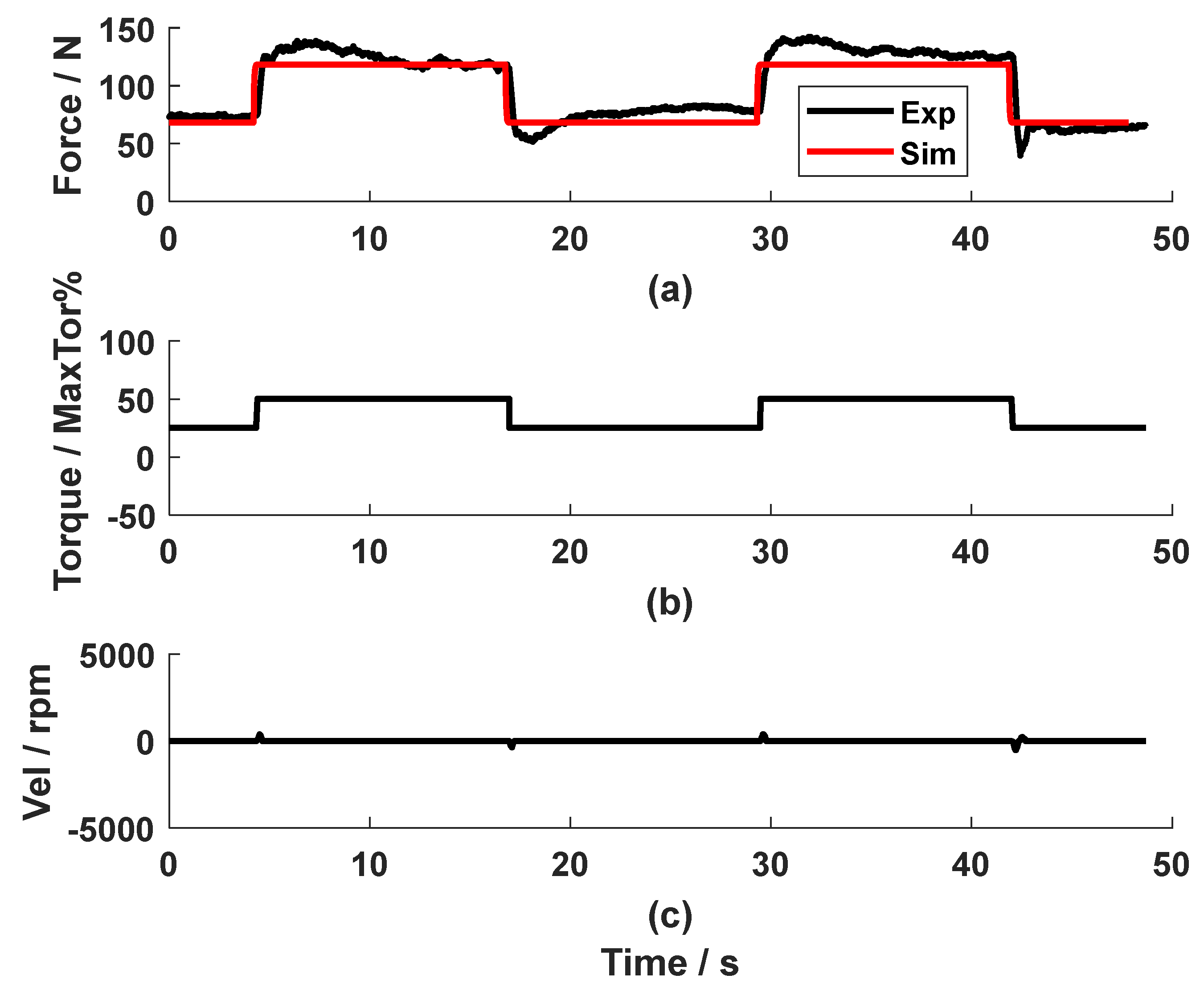
Figure 4.
The static test of the PI force feedback controller with a square-wave reference.
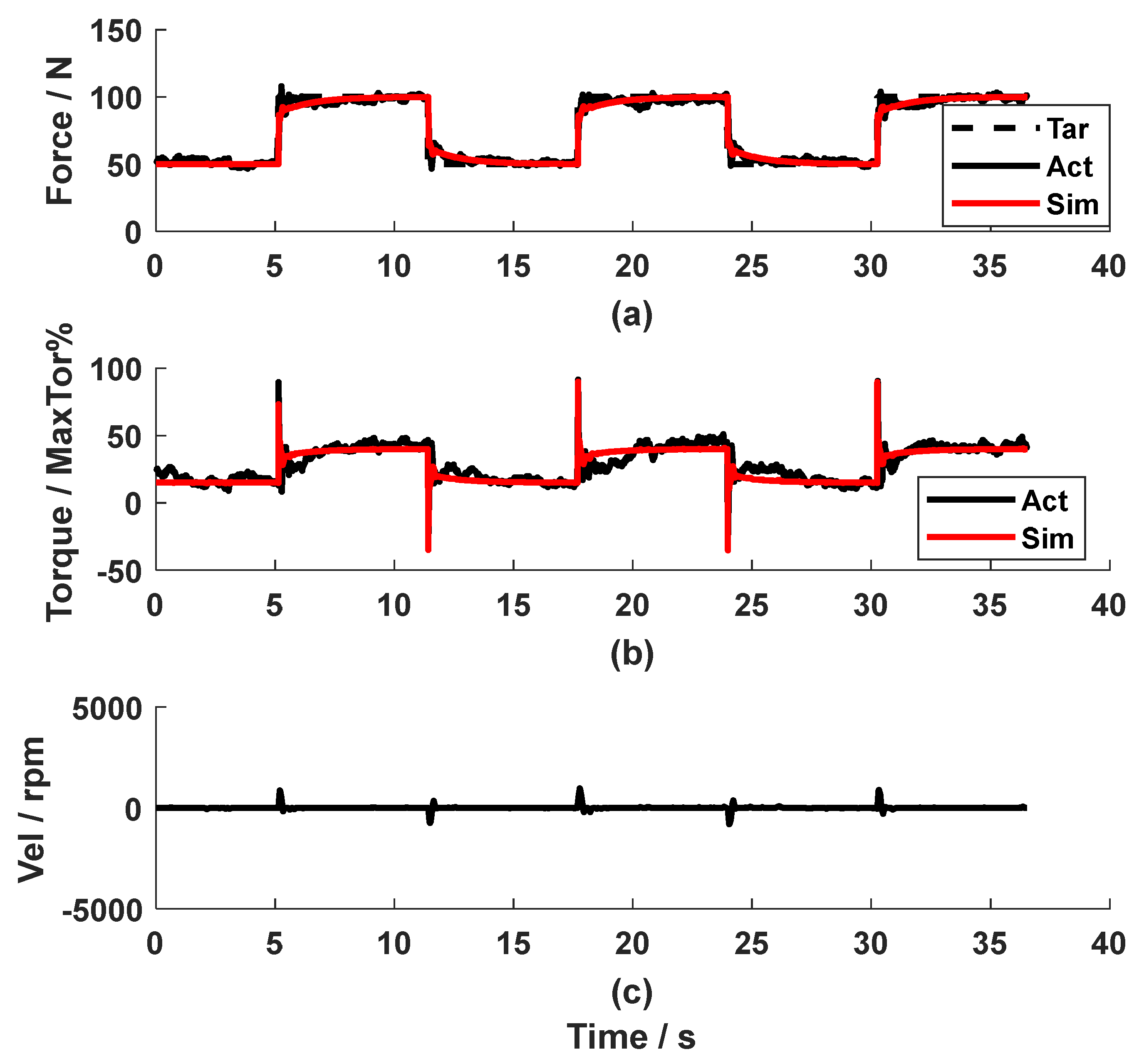
Figure 5.
The static test of the PI force feedback controller with a sinusoidal reference.
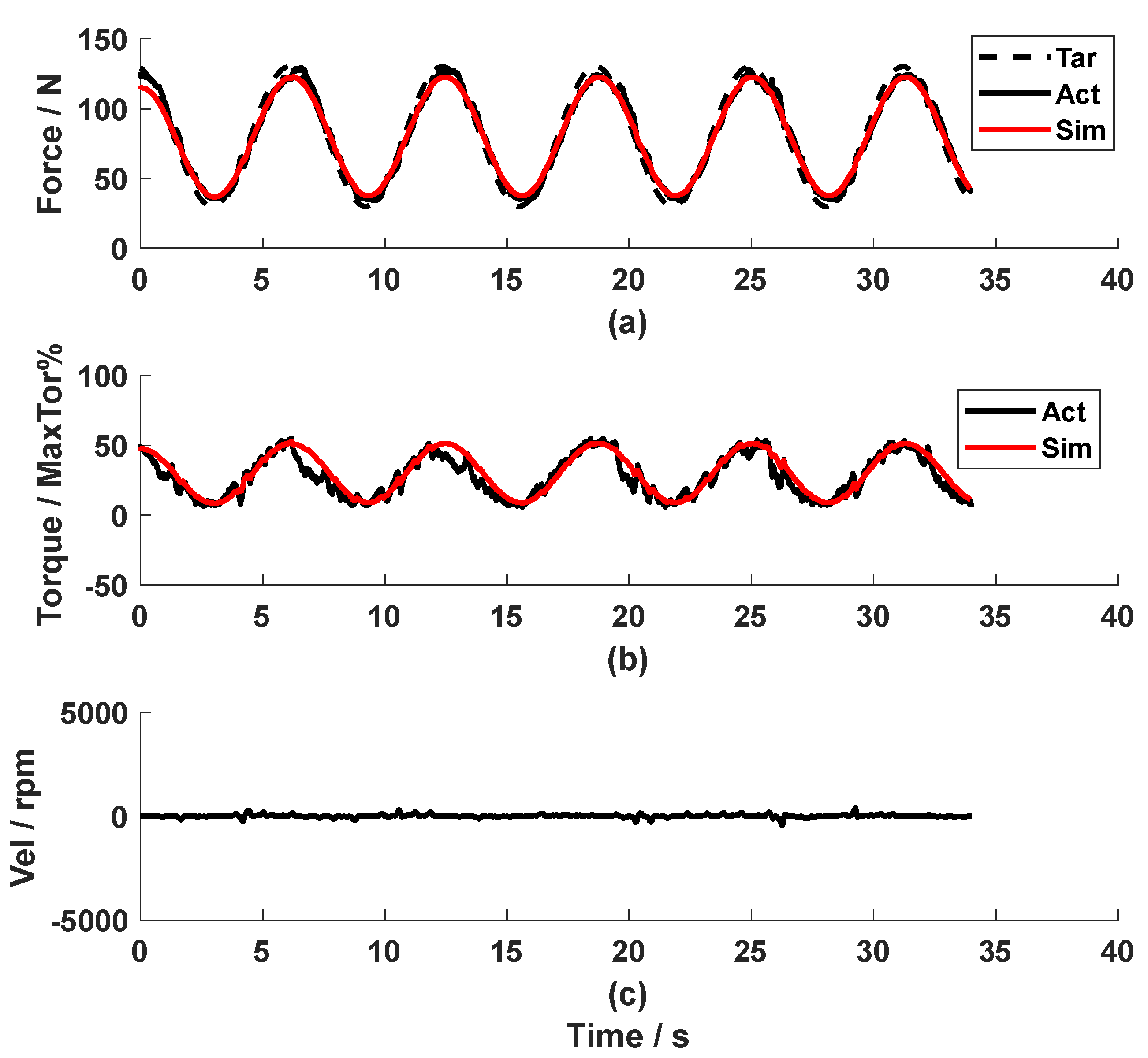
Figure 6.
The dynamic test of the PI force feedback controller only (Metronome beat: 60 BPM).
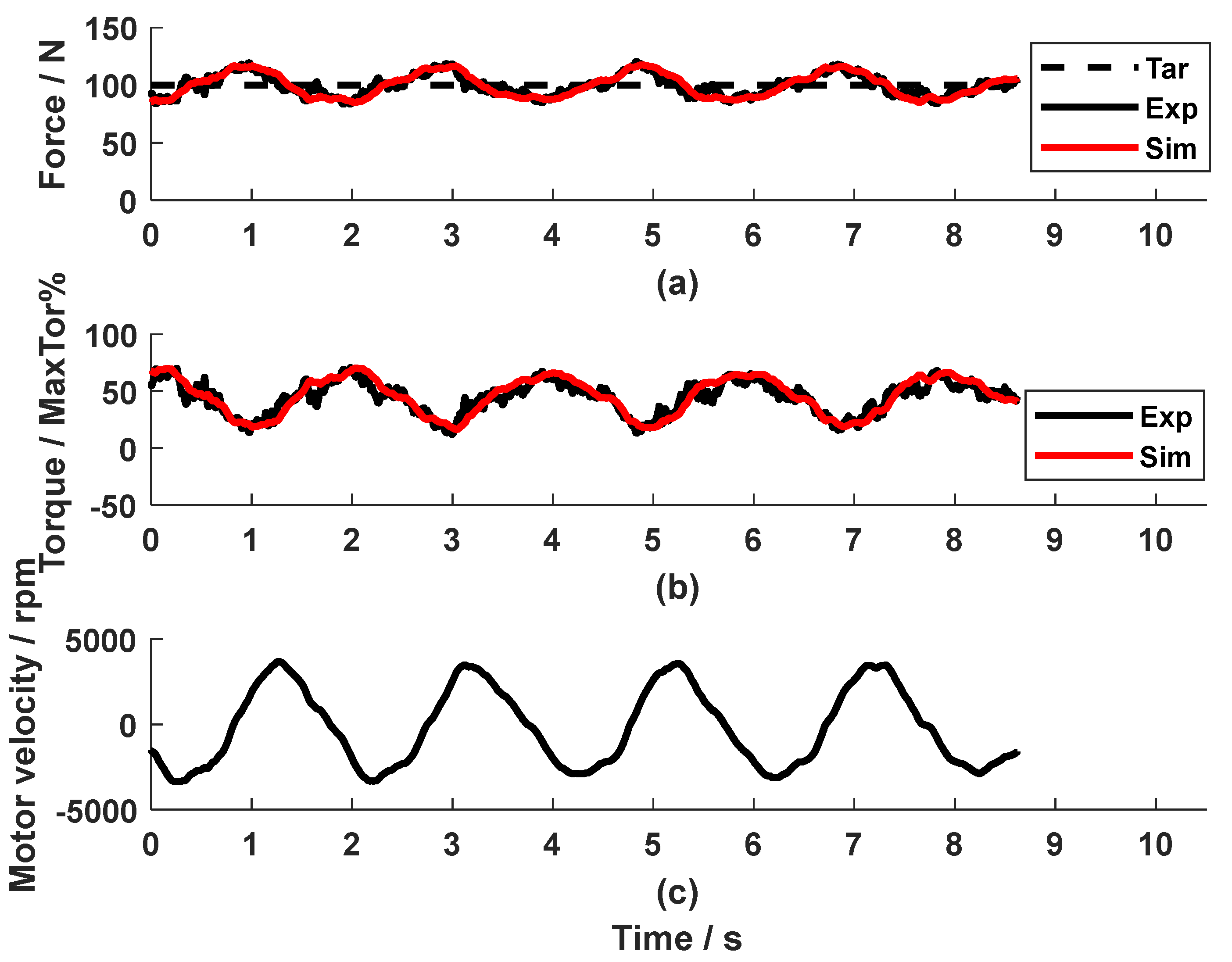
Figure 7.
The frequency response of the speed disturbance to the force output.
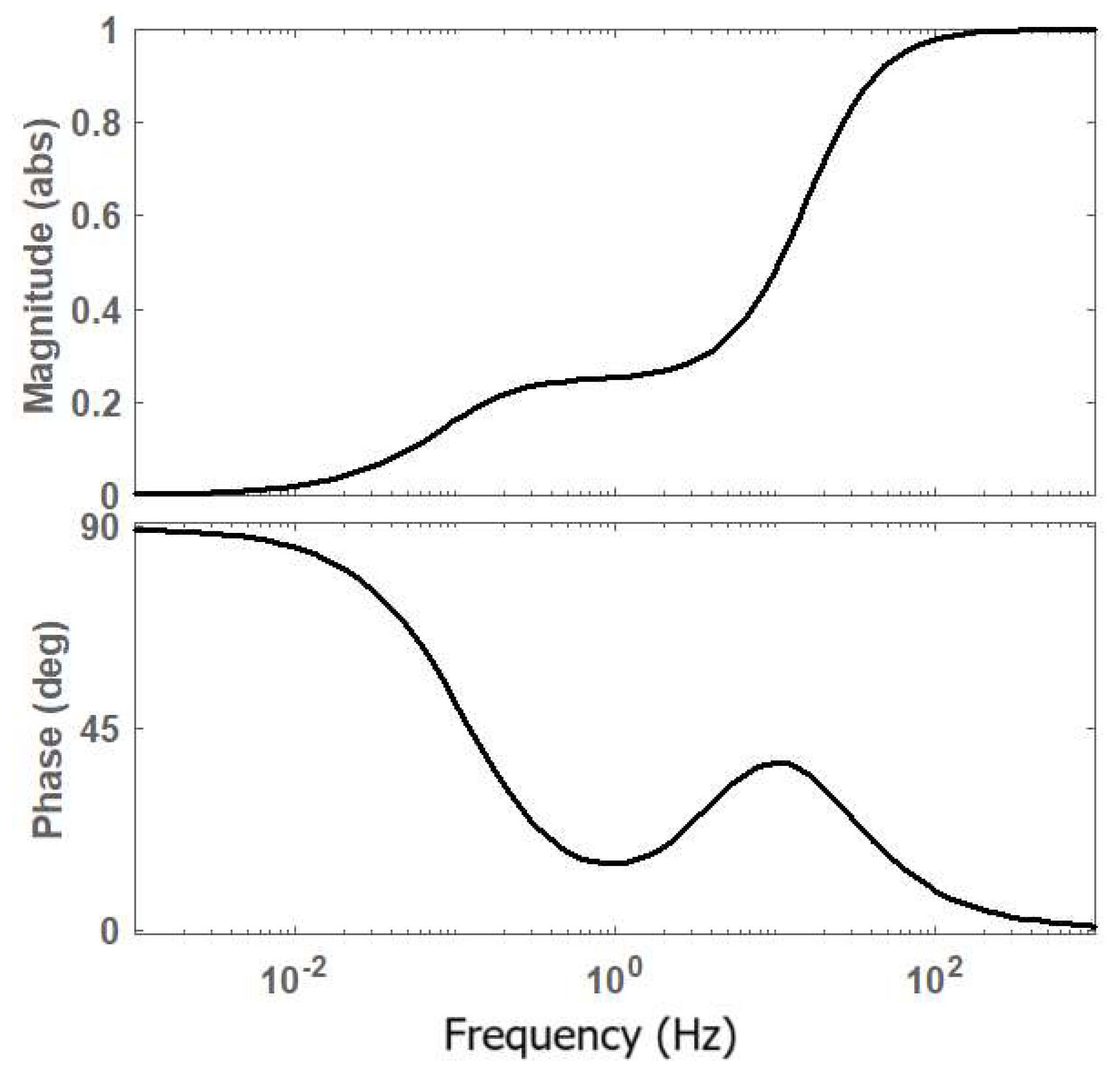
Figure 8.
The influence of the motor speed on the force control accuracy.
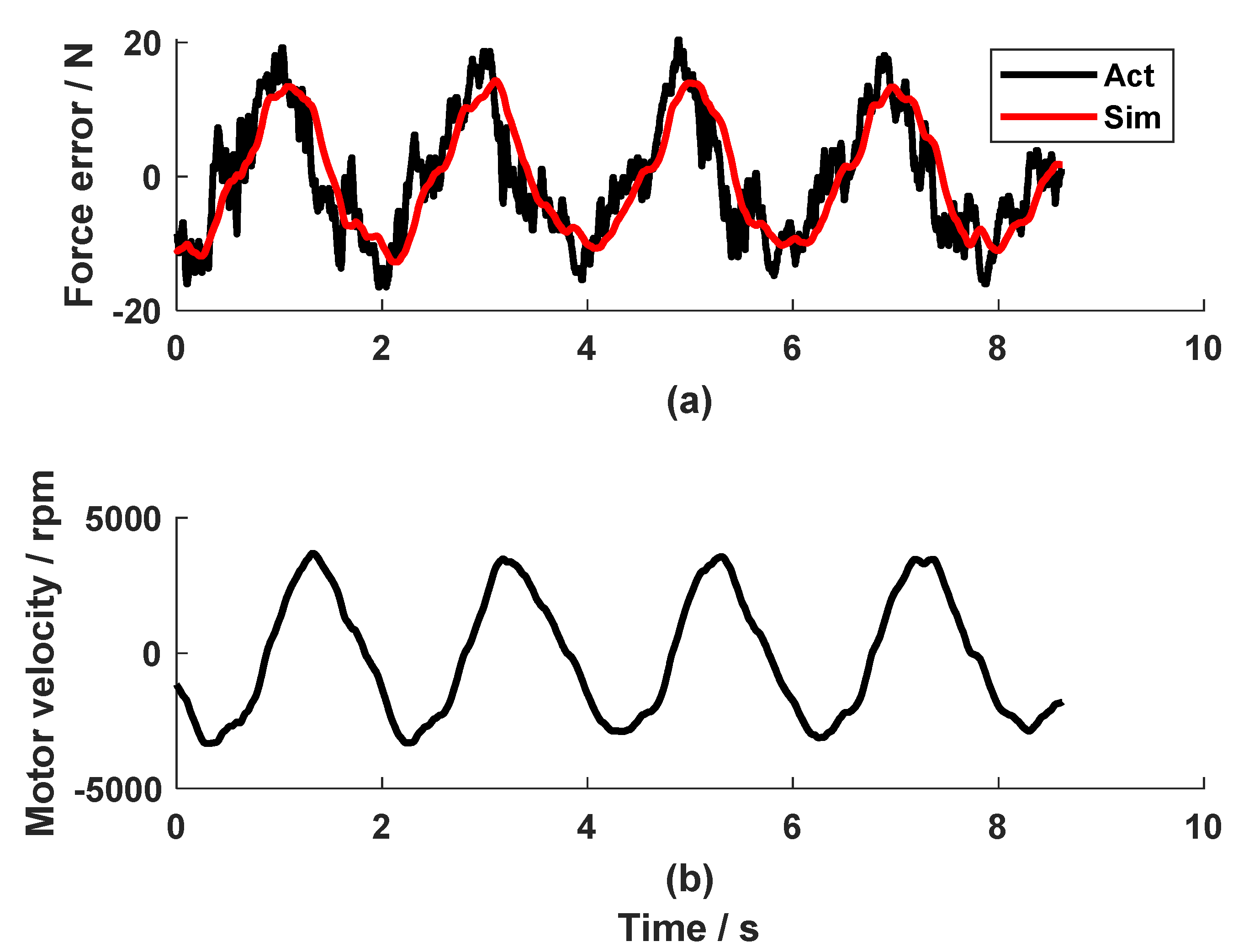
In contrast to the very good force-tracking accuracy in the static test, repetitive pulling and releasing the cable of the CDA yielded a large force error when the PI controller alone was used. As shown in Fig. 6, an RMSE_Fexp_r of 9.0 N was observed during a rhythmic pull at 60 BPM. It could be observed that the force error took a similar shape to the speed profile but with a lower amplitude and a certain phase shift.
The Bode diagram of So shows how the motor speed signal influences the system force output. As shown in Fig. 7, the speed signal with a frequency higher than 100 Hz will almost reappear in the force output. The physical movement frequency range during arm training is between 20-240 BPM, i.e. 0.17-2.0 Hz. Regarding this frequency range, the signal will appear in the force output with an amplitude reduced to be 0.21-0.27 times and a phase shift of 15-24o.
The test data during movement at 60 BPM (Fig. 6) show an input velocity with a frequency of about 0.5 Hz. The Bode diagram (Fig. 7) yields that for this velocity frequency, the amplitude is 0.246, i.e., Gd = 0.246, while the phase shift is only 17.53o. Therefore, in the control diagram (Fig. 2), the gain G was set to be 4 (using Eq.4).
The System Identification Toolbox yielded the experimental-obtained relationship Pω of the motor speed ω and the force as:
The goodness of fit was 68.1% (see Fig. 8). Therefore, the implemented feedforward compensator, using Eq.5, is:
Implementing the feedforward compensator and the PI feedback controller, the dynamic test showed an RMSE_Fexp_r of 5.6 N (Fig. 9), which means satisfactory force control accuracy. Compared to Fig.6, the feedforward compensator reduced the force error by 3.4 N.
Figure 9.
The dynamic test of the PI force feedback controller and the speed feedforward compensator (Metronome beat: 60 BPM).
Figure 9.
The dynamic test of the PI force feedback controller and the speed feedforward compensator (Metronome beat: 60 BPM).
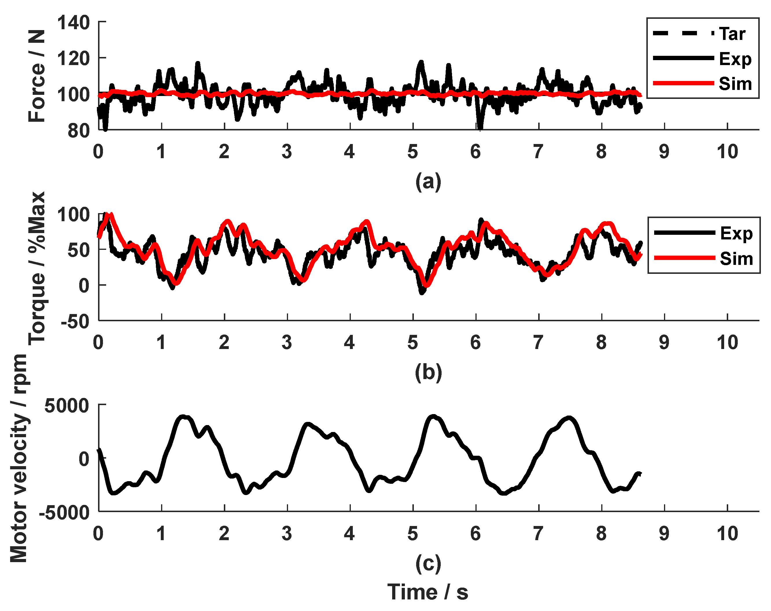
Figure 10.
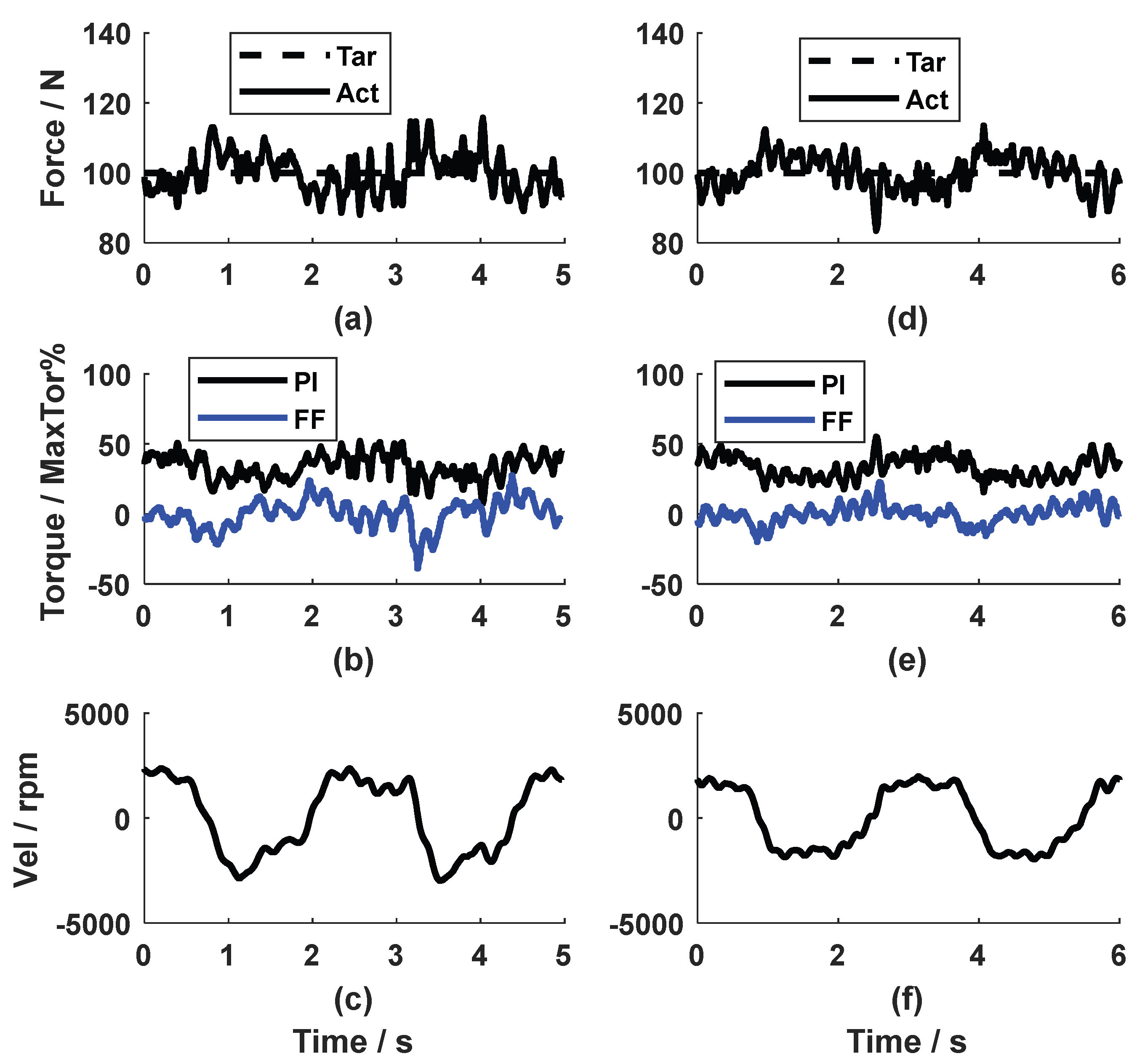
The dynamic test of the PI force feedback controller and the speed feedforward compensator. Subfigures a-c: Metronome beat: 50 BPM. Subfigures d-f: Metronome beat: 40 BPM.
Figure 10.
The dynamic test of the PI force feedback controller and the speed feedforward compensator. Subfigures a-c: Metronome beat: 50 BPM. Subfigures d-f: Metronome beat: 40 BPM.
Regarding the simulation results of the dynamic tests, the simulated force and the control torque sign for the motor (the red line in Fig. 6a and Fig. 6b) with the PI force feedback controller only were close to the corresponding experimental value (the black line in Fig. 6a and Fig. 6b) with an RMSE_Fexp_sim of 4.4 N, RMSE_Texp_sim of 9.2%. In the simulation for the combined PI force feedback controller and the speed compensator, the simulated values were similar to the experimental value, too (the red and black line in Fig. 9a for the force, the red and black line in Fig. 9b for the torque) with an RMSE_Fexp_sim of 5.4 N, RMSE_Texp_sim of 18.8%. This means that the model with the force feedback controller plus the speed feedforward compensator yielded a satisfactory simulation. These results validated the parameter identification of the disturbance Pω. As far as the development of the speed compensator was concerned, the simulated force output (red line in Fig. 9a) is very close to the reference force (dashed black line in Fig. 9a) with an RMSE_Fsim_r of 0.8 N. This proved that the developed feedforward compensator (Eq. 11) was theoretically correct. The minor difference between the simulated force output and the reference force might come from the approximation of the disturbance Pω. Due to the simplification of plant Po, it was expected that the experimental force output with the feedforward compensator (black line in Fig. 9a) was not as good as the simulated result (red line in Fig. 9a).
The feedforward compensator was tested at various speeds. As seen in Fig. 10, the experimental force output at 50 and 40 BPM tracked the reference force satisfactorily, with an RMSE_Fexp_r of 5.5 N (Fig. 10a) and 5.6 N (Fig. 10d), respectively. The control signal calculated by the PI controller and the compensator could be seen in Fig. 10 (b, e). It is observed that the torque produced by the PI controller from both cases were very similar, while the torque from the feedforward compensator had a larger range in amplitude at 50 BPM, because the motor velocity at 50 BPM was higher. The speed feedforward compensator, developed based on the data from 60 BMP, also compensated the disturbance produced by the movements at 40 BPM and 50 BPM.
4. Discussion
Accurate control of cable tension during movement is essential for effective application of cable-driven robotic systems in rehabilitation. In this work, we developed a force feedback controller and a speed feedforward compensator for a CDA, which produced satisfactory force control during movement at various speeds. Using experimental data, the system dynamics and the speed disturbance were identified. Simulation results agreed with the experimental results, validating the system identification results. After being tested in dynamic arm training at various speeds, the control strategy was proven to be satisfactory. The force control strategy served as a solid foundation for further development of the high-level position control of CDAs, which is to be produced by general cable-driven rehabilitation systems.
The PI force feedback controller produced very good control accuracy in the static test of the CDA. While the CDA offers a user-friendly physical interface, the soft cable property and the nonlinear dynamics of CDA during movement make it challenging to control the cable tension accurately. In the current study, the conventional PI controller was employed, which produced very good accuracy in static force control (mean RMSE_Fexp_r of 4.7 N). Such conventional controllers were often used in the literature [8,11,12]. The advantage of this approach is that it does not require an accurate plant model. As system simulation in the study and the further development of the speed compensator required a system model, we still worked out the transfer function of the CDA. Instead of using the theoretical deduction [3,10], we simplified the CDA dynamics to be a first-order system, without considering the compliant properties of the cable. The experimental force output and the control signal agreed with the simulation results (mean RMSE_Fexp_sim of 4.0 N, mean RMSE_Texp_sim of 6.0% of the maximal torque). It was demonstrated that the approximated first-order system produced very good simulation results for the static CDA. The plant parameters using the System Identification Toolbox were proven to be feasible. Since the plant transfer function Po was obtained, a force lead controller, as implemented in our previous study [14], could be developed in the current study to improve the force control performance.
The main innovation of this study was the experimental development of the speed feedforward compensator for dynamic force test of CDA. Compensation of the unwanted force produced by the motor speed is a tricky task [2,3]. As summarised in the introduction, some researchers used an experimental approach to determine the friction-speed relationship [7,8,11,12], while others employed a theoretical method to develop a speed compensator [3,10,14]. Both approaches yielded good results after repetitive testing or sophisticated deduction. This study provided an innovative experimental approach. The feedback PI controller enabled the CDA to perform dynamic tests, allowing for an experimental analysis of velocity disturbances. Using the System Identification Toolbox, a second-order relationship between the motor speed and the force output, Pω, was obtained. The PI controller combined with the speed compensator produced satisfactory force tracking accuracy (mean RMSE_Fexp_r at 40, 50 and 60 BPM of 5.6 N). This relationship Pω possibly represents the influence on the CDA force output from the factors such as friction, moments of inertia, and the spring-damper properties of the cable. Testing the control strategy in dynamic conditions showed that the speed compensator further reduced more than one third of the force error. It should be noted that the speed compensator was developed based on experimental data at 60 BPM. The dynamic tests at 50 and 40 BPM also yielded satisfactory force control results. However, further investigation is needed to determine the effective speed range of the compensator. Nonetheless, in this study, we developed the speed compensator using experimental data, which is a convenient approach compared to the compensators in [2,3,10] and our previous study [14]. The control strategy produced satisfactory force control accuracy.
This study has limitations and requires future work. This study approximated the dynamic model of CDA Po as a first-order system. The plant can be improved by integrating the spring-damper property of the cable element into the transfer function Po. The approximation of the speed disturbance as a second-order model was developed and validated based on the data within a relatively narrow speed range. An extensive analysis of the disturbance should be carried out at a large speed range. Another limitation was that the parameters for the PI force controller were determined by trial and error. Better force control strategies will be further investigated. Pole assignment can be a promising approach for developing the force feedback controller [18]. Through shaping the input sensitivity, the speed disturbance might also be rejected [19]. Future work can be integration of the speed compensator into better feedback algorithms for more accurate force control during dynamic movement.
5. Conclusions
An innovative force control strategy for the cable-driven actuator was developed in this work, which consists of a force feedback controller and a speed feedforward compensator. Dynamic tests with the PI force controller revealed the influence of speed disturbances on the force output, which enabled the further development of the feedforward compensator. The control strategy was proven to track the force satisfactorily in dynamic tests at various speeds. The combined feedback and feedforward controllers show potential to be used for accurate force control of general CDAs, which is an essential basis for precise movement control of cable-driven rehabilitation robotic systems.
Author Contributions
Conceptualization, Juan Fang, Michael Haldimann and Robert Riener; Data curation, Juan Fang, Michael Haldimann and Bardia Amiryavari; Formal analysis, Juan Fang, Michael Haldimann and Bardia Amiryavari; Funding acquisition, Juan Fang and Robert Riener; Investigation, Juan Fang and Michael Haldimann; Methodology, Juan Fang, Michael Haldimann, Bardia Amiryavari and Robert Riener; Project administration, Juan Fang; Resources, Bardia Amiryavari; Software, Michael Haldimann and Bardia Amiryavari; Supervision, Juan Fang and Robert Riener; Validation, Juan Fang and Michael Haldimann; Writing – original draft, Juan Fang; Writing – review & editing, Juan Fang, Michael Haldimann, Bardia Amiryavari and Robert Riener. All authors have read and agreed to the published version of the manuscript.
Funding
This research was funded by Swiss National Science Foundation, grant number 32HW-0_220453.
Data Availability Statement
Data are contained within the article.
Conflicts of Interest
The authors declare no conflicts of interest.
References
- Stefano Mazzoleni, Antonella Focacci, Marco Franceschini, Andreas Waldner, Chiara Spagnuolo, Elena Battini, and Donatella Bonaiuti. Robot-assisted end-effector-based gait training in chronic stroke patients: A multicentric uncontrolled observational retrospective clinical study. NeuroRehabilitation, 2017. 40(4): p. 483-492. [CrossRef]
- Lailu Li, Lixun Zhang, Bing Wang, Feng Xue, Yupeng Zou, and Da Song. Running experimental research of a cable-driven astronaut on-orbit physical exercise equipment. Machines, 2022. 10(5): p. 377. [CrossRef]
- Yupeng Zou, Huizi Ma, Zhiyuan Han, Yang Song, and Kai Liu. Force control of wire driving lower limb rehabilitation robot. Technology and Health Care, 2018. 26: p. S399–S408. [CrossRef]
- Ying Mao, Xin Jin, Geetanjali Gera, John Scholz, and Sunil K. Agrawal. Human movement training with a cable driven ARm EXoskeleton (CAREX). IEEE Transactions on Neural Systems and Rehabilitation Engineering, 2015. 23(1): p. 84-92. [CrossRef]
- Yupeng Zou, Xiangshu Wu, Baolong Zhang, Qiang Zhang, Andong Zhang, and Tao Qin. Stiffness analysis of parallel cable-driven upper limb rehabilitation robot. Micromachines, 2022. 13(2). [CrossRef]
- Joachim Von Zitzewitz, Andre Morger, Georg Rauter, Laura Marchal-Crespo, Francesco Crivelli, Dario Wyss, Tobias Bruckmann, and Robert Riener. A reconfigurable, tendon-based haptic interface for research into human-environment interactions. Robotica, 2013. 31: p. 441-453.
- Laura Marchal-Crespo, Georg Rauter, Dario Wyss, Joachim von Zitzewitz, and Robert Riener. Synthesis and control of an assistive robotic tennis trainer. in 4th IEEE RAS & EMBS International Conference on Biomedical Robotics and Biomechatronics (BioRob). 2012.
- Vineet Vashista, Xin Jin, and Sunil K. Agrawal. Active Tethered Pelvic Assist Device (A-TPAD) to study force adaptation in human walking. in 2014 IEEE International Conference on Robotics and Automation (ICRA). 2014.
- Moiz I. Khan, Victor Santamaria, Jiyeon Kang, Brian M. Bradley, Joseph P. Dutkowsky, Andrew M. Gordon, and Sunil K. Agrawal. Enhancing seated stability using Trunk Support Trainer (TruST). IEEE Robotics and Automation Letters, 2017. 2(3): p. 1609-1616. [CrossRef]
- Lixun Zhang, Lailu Li, Yupeng Zou, Keyi Wang, Xize Jiang, and Haoran Ju. Force control strategy and bench press experimental research of a cable driven astronaut rehabilitative training robot. IEEE Access, 2017. 5: p. 9981-9989. [CrossRef]
- Rand Hidayah, Lauri Bishop, Xin Jin, Siddharth Chamarthy, Joel Stein, and Sunil K. Agrawal. Gait adaptation using a cable-driven active leg exoskeleton (C-ALEX) with post-stroke participants. IEEE Transactions on Neural Systems and Rehabilitation Engineering, 2020. 28(9): p. 1984-1993. [CrossRef]
- Anna-Maria Georgarakis, Jaeyong Song, Peter Wolf, Robert Riener, and Michele Xiloyannis. Control for gravity compensation in tendon-driven upper limb exosuits. in 2020 8th IEEE RAS/EMBS International Conference for Biomedical Robotics and Biomechatronics (BioRob). 2020. IEEE.
- Juan Fang and Kenneth J. Hunt. Development of a cable-driven device for neuromuscular rehabilitation in International Conference on Neurorehabilitation (ICNR). 2024. La Granja, Spain: Springer Nature.
- Juan Fang, Michael Haldimann, Laura Marchal-Crespo, and Kenneth J. Hunt. Development of an active cable-driven, force-controlled robotic system for walking rehabilitation. Frontiers in Neurorobotics, 2021. 15(49). [CrossRef]
- Juan Fang and Michael Haldimann. Technical development and preliminary physiological response investigation of a tendon-based robotic system for gait rehabilitation. Brain Network and Modulation, 2024. 3(4): p. 79-90. [CrossRef]
- Hamed Jamshidifar, Saeid Khosravani, Baris Fidan, and Amir Khajepour. Vibration decoupled modeling and robust control of redundant cable-driven parallel robots. IEEE/ASME Transactions on Mechatronics, 2018. 23(2): p. 690-701. [CrossRef]
- Juan Fang, Michael Haldimann, Bardia Amiryavari, Efe Anil Aksöz, and Robert Riener. Development of a mobile gait trainer using pose estimation. in International Conference on Neurorehabilitation (ICNR). 2024. La Granja, Spain: Springer Nature.
- Hamed Jamshidifar, Baris Fidan, Gokhan Gungor, and Amir Khajepour. Adaptive vibration control of a flexible cable driven parallel robot. IFAC-PapersOnLine, 2015. 48(3): p. 1302-1307. [CrossRef]
- Hanjie Wang and Kenneth J. Hunt. Self-paced heart rate control for treadmill exercise. Frontiers in Control Engineering, 2023. 4. [CrossRef]
Disclaimer/Publisher’s Note: The statements, opinions and data contained in all publications are solely those of the individual author(s) and contributor(s) and not of MDPI and/or the editor(s). MDPI and/or the editor(s) disclaim responsibility for any injury to people or property resulting from any ideas, methods, instructions or products referred to in the content. |
© 2025 by the authors. Licensee MDPI, Basel, Switzerland. This article is an open access article distributed under the terms and conditions of the Creative Commons Attribution (CC BY) license (http://creativecommons.org/licenses/by/4.0/).
Copyright: This open access article is published under a Creative Commons CC BY 4.0 license, which permit the free download, distribution, and reuse, provided that the author and preprint are cited in any reuse.


