Submitted:
04 March 2025
Posted:
05 March 2025
You are already at the latest version
Abstract
In this study, we designed and fabricated a lightweight and high-precision K-band corrugated horn antenna with a wide operating frequency using chemical silver plating and three-dimensional (3D) printing technology. The corrugated horn antenna was mainly made of polymer materials, with a metal silver coating on the inner surface, and its mass was only 17% of that of a steel corrugated horn antenna. 3D printing technology achieved the integrated solidification and molding of the complex internal structure of the K-band corrugated horn antenna. The antenna had a return loss mostly below −20 dB in the range of 18.0–27.0 GHz and a gain of over 14 dB in the range of 18.0–24.0 GHz. The measured results of the directional pattern agreed well with the simulation results. This technology is expected to bring revolutionary changes to the overall design and manufacturing process of small satellites and radar systems.
Keywords:
corrugated horn antenna
; K-band
; high precision
; lightweight antenna
; additive manufacturing
; chemical silver plating
; 3D printing
; small satellites
; radar systems
1. Introduction
In recent years, K-band broadband satellite communication has emerged as the primary research direction of broadband satellite communication given its advantages, such as high throughput, low cost, wide coverage, and small terminals, offering great potential for diverse application prospects. Meanwhile, the application of K-band in fields such as radio astronomy, microwave remote sensing, and relay communication is becoming increasingly widespread [1,2]. The payload of K-band communication satellites generally uses large reflector antennas, and the performance of the feed source as the “heart” of the reflector antennas directly affects the radiation characteristics of the reflector. The primary requirements for the antenna are wideband performance, effective cross-polarization, and stable phase center characteristics [3].
Horn antennas have good directionality, low cost, and small size, making them suitable for satellite communication with strict antenna size requirements. At present, conical and corrugated horns are mainly used as feed sources for high-performance reflector antennas [4,5]. Conical horns are generally smaller in size than corrugated horns because of their lack of corrugated grooves. The structure of conical horns is simpler and easier to prepare and is easy to integrate and form. Therefore, in narrower frequency bands, conical horns can replace corrugated horns, whereas for wider frequency bands, corrugated horns are more suitable [6]. Conical horn antennas have some current flowing from their inner wall to the outer wall at their terminal opening, which affects the performance of the antennas. To prevent current from flowing toward the outer wall, corrugated grooves are carved on the inner wall of conical horn antennas, forming corrugated horn antennas (Figure 1). Compared with conical horn antennas, corrugated horn antennas can reduce edge diffraction, improve directional symmetry, and reduce cross-polarization levels [7].
The three-dimensional geometric shape of corrugated horns is complex, with extensive specifications for dimensional accuracy and surface roughness. If applied in satellite communication systems, lightweight materials must also be considered in material selection [8]. For the manufacturing of corrugated horns with complex internal structures, conventional mechanical processing techniques are complex and difficult and increase manufacturing costs [9,10].
Three-dimensional (3D) printing technology, a subset of additive manufacturing, employs a layer-by-layer material deposition approach to efficiently produce complex structural parts. The rapid preparation of microwave passive components and other products using additive manufacturing technology has optimized the production process of radar equipment manufacturing, effectively ensuring the success rate of radar equipment development. This technology is expected to bring revolutionary changes to the overall design and manufacturing process of radar equipment [11,12].
3D printing technology is becoming increasingly widely used in the processing and application of complex structured antennas. For instance, Diogo Helena et al. used 3D printing technology to manufacture metal antennas for 5G transmission. After copper plating treatment, the antenna had a gain of 12–13 dB at 26–30 GHz [13]. Meanwhile, Jana Olivová et al. used a 3D commercial printer to manufacture a standardized horn antenna. The horn antenna had the same parameters as that of a standard horn antenna after electroplating with gold and silver [14]. Jia-Chi Samuel Chieh et al. used a 3D printer to prepare a corrugated conical horn antenna (10–16 GHz). The printing material was acrylonitrile butadiene styrene thermoplastic, and a layer of conductive aerosol paint was then applied on the surface of the material. The measured cross-polarization level was at least 20 dB away from the main lobe [15]. Wang et al. 3D printed a lightweight monolithic circularly polarized K-band horn antenna and metalized the material using a novel charge-programmed deposition method. The measurement results of the horn were highly consistent with the simulation results, with an axial ratio below 2.5 dB in the range of 17.5–20.5 GHz [16]. Oktafiani et al. developed a broadband dual-polarization, four-ridge horn antenna using 3D printing technology. Isolation between ridges below −20 dB was achieved in most frequency ranges [17].
Because of printing accuracy limitations, most conical horn antennas currently prepared using 3D printing have simple structures. Corrugated horn antennas were prepared in some studies, but because of the inability to ensure the uniformity of the metal coating, these antennas were designed in several parts, which were metalized separately and combined thereafter. Herein, a digital light processing (DLP) 3D printing machine with the highest printing accuracy and efficiency was used. The printing screen resolution was 14 K (13,320 × 5,120 px), and the pixel size was 16.8 × 24.8 μm. The corrugated horn antenna with a micrometer internal structure could be integrated and solidified using this device.
We designed a lightweight and wideband corrugated horn antenna with low cross-polarization, symmetry radiation pattern, and phase center stability to meet the needs of K-band broadband satellite communication. Our design was validated through sample processing, testing, and result comparison (Figure 2).
2. Materials and Methods
2.1. Materials Preparation
The resin matrix of the corrugated horn antenna was prepared using a commercial 3D printer, Creality HALOT-MAGE S (Shenzhen Creality 3D Technology Co., Ltd.). 4-Acryloylmethiolane (ACMO), an aliphatic polyurethane acrylate, was sourced from Shanghai Yinchang New Materials Co., Ltd. 2,4,6-Trimethylbenzoyl diphenyl phosphine oxide (TPO) was obtained from Tianjin Jiuri New Materials Co., Ltd. The 3D printing resin was prepared by mixing and stirring 37wt% of aliphatic polyurethane acrylate, 60wt% of ACMO, and 3% of TPO. After preparing the corrugated horn antenna model through 3D printing, the resin model was cleaned and degreased first using a mixed alkaline solution of c (NaOH) = 60 g L−1 and c (Na2CO3) = 20 g L−1 at 45°C. An aqueous suspension of 0.5 g L−1 TiO₂ was added into the corrugated horn chamber and irradiated with ultraviolet light for 30 min. A sensitization solution (SnCl2·H2O [30 g L−1] + 37% hydrochloric acid [50 mL L−1]) and an activation solution (PdCl2 [1 g L−1] + 37% hydrochloric acid [10 mL L−1]) were added into the resin model cavity and shaken for 2 min. The resin model was cleaned and dried with deionized water during the intermediate process. Subsequently, chemical silver plating was conducted under the following optimal process conditions: AgSO4, 9.2 g L−1; NH3·H2O, 18.5 mL L−1; glucose, 22.5 g L−1; ethanol, 50 mL L−1. The mixed silver plating solution was added into the model cavity at a temperature of 30°C for 50 min, and the plating process was repeated five times. The technological process diagram is shown in Figure 3.
For the K-band, we designed a corrugated horn with an aperture angle of 17°, a ripple depth of 1.6 mm, and a width of 1.0 mm. The size of the antenna is shown in Figure 4b. The antenna could be divided into three parts considering their functionality: (i) a rectangular circular waveguide transformation section (length = 18.0 mm); (ii) a circular waveguide transition section (length = 17.0 mm); and (iii) an axial slots radiation section (length = 40.0 mm). Finally, a commercially available coax-to-WR-42 adapter was directly connected to the transition section of the rectangular circular waveguide, which was used for excitation. The axial slot radiation section of the antenna was optimized using the pattern-matching method to meet the requirements of coaxial feeding.
We used the CST Microwave Studio (2019) software to simulate the three-dimensional model of the antenna to verify the accuracy of the pattern-matching method calculation and optimize the antenna’s return loss by adjusting the rectangular circular waveguide transformation section. Figure 4a shows the overall cross-sectional views of the optimized circular waveguide transition section, the rectangular circular waveguide transformation section, and the rectangular waveguide transition section with good impedance characteristics. Then, the corrugated horn was combined with a standard coax-to-WR-42 adapter to obtain complete return loss and radiation pattern results.
2.2. Characterization
The morphology and microstructure of the 3D printing materials were characterized using a field-emission scanning electron microscope (SEM, Hitachi, su8010, Japan). The manufactured horn was assembled with a coax-to-WR-42 adapter from Narda, and the antenna was then transferred to the coaxial port. The reflection coefficient (S11) of the horn antenna was tested in the range of 18.0–27.0 GHz. The radiation pattern of the corrugated horn was then measured in the far-field antenna measurement system (Figure 5) at Shaanxi Shibei Communication Technology Co., Ltd.
3. Results
3.1. Microstructure Characterization of 3D-Printed Corrugated Horn with Chemical Silver Plating
The manufacturing process, including 3D printing, preprocessing, electroplating, and postprocessing, can be completed in 1 day at low material costs. The weight of the horn was only 41.3 g, which was about 83% less than the weight of a steel corrugated horn of the same size manufactured using traditional methods, as shown in Figure 6a. According to the cross-sectional image of the antenna captured by a scanning electron microscope (SEM), the thickness of the silver coating was 5.2 µm, which could produce a significant skin depth, as shown in Figure 6b.
3.2. Simulated and Measured Results of 3D-Printed Corrugated Horn with Chemical Silver Plating
The reflection coefficient (S11) of the horn antenna was tested in the range of 18.0–27.0 GHz. The simulation and measurement results are shown in Figure 7a. The return loss value was around −20 dB, and the highest measured reflection coefficient within the operating frequency band was −40.9 dB. The differences between the test and simulation results could be attributed to the combined effects of manufacturing tolerances, measurement uncertainty, and simulation software calculation errors [18].In Figure 7b, the gain of the manufactured corrugated horn was measured using the substitution method with reference to the Narda 638 standard gain horn. The gain of the antenna was measured to be above 10 dB in the test frequency band and above 14 dB in the 18- to 24-GHz range.
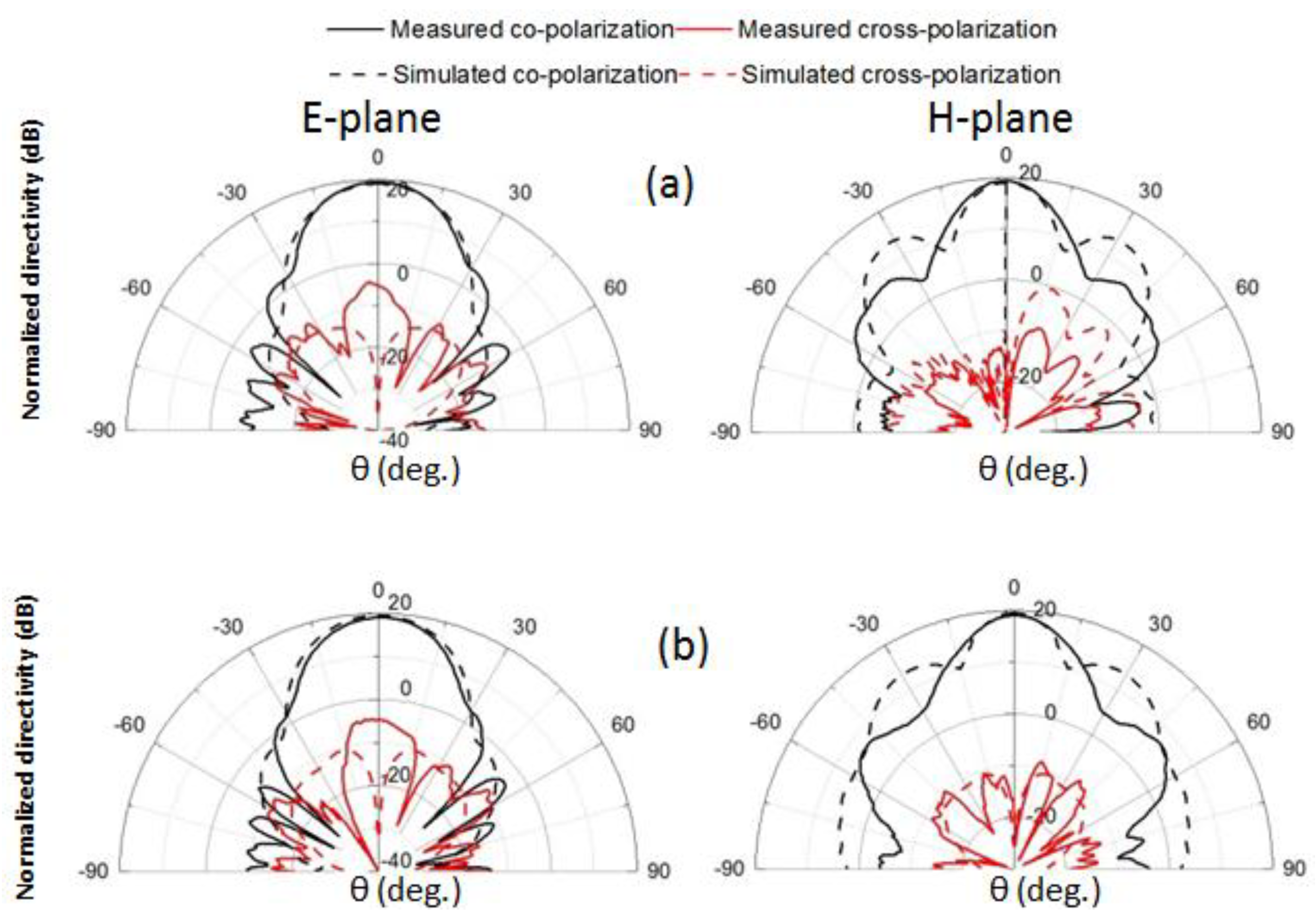
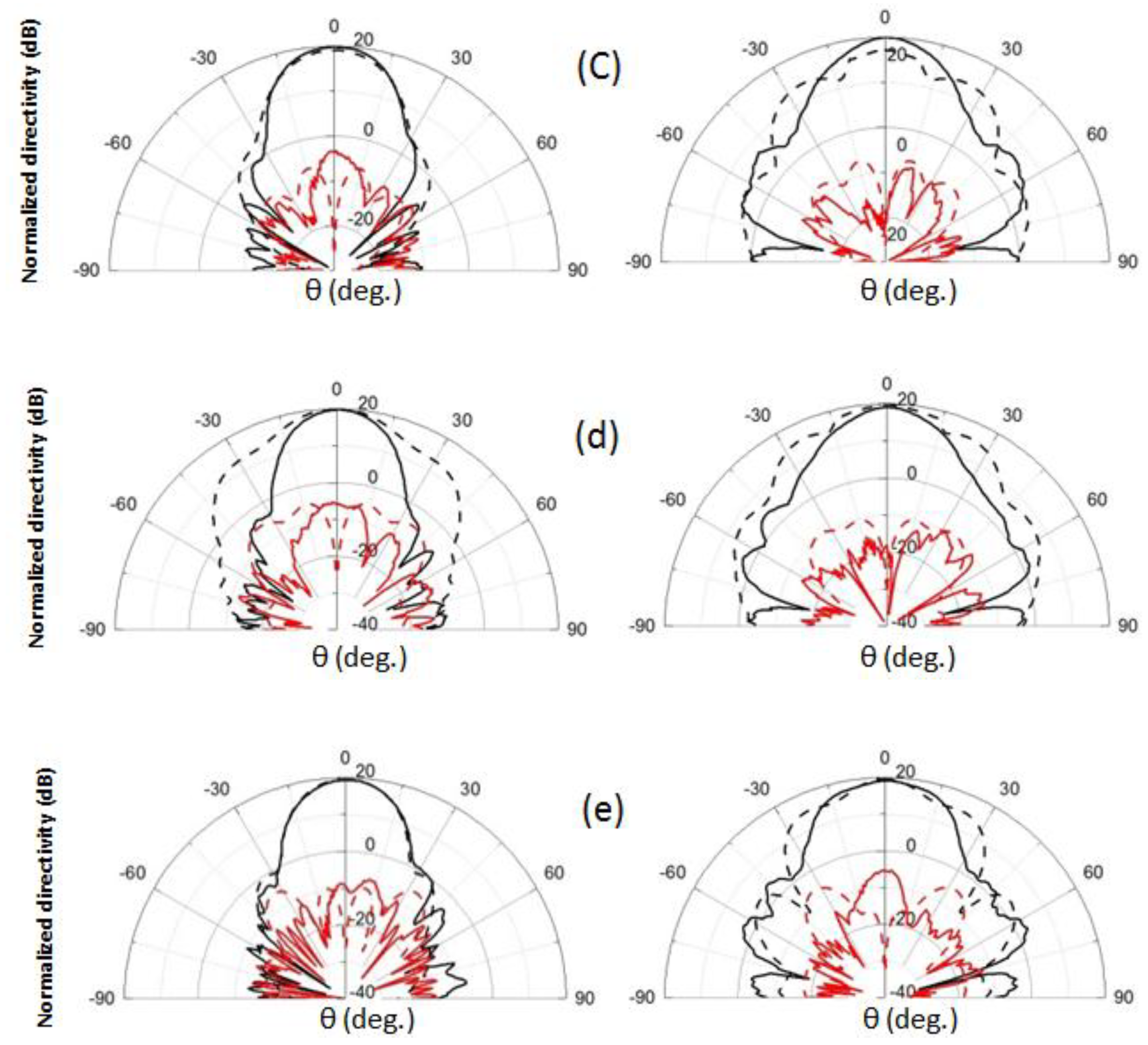
The copolarized and cross-polarized radiation patterns of the E-plane and H-plane horns were measured (Figure 8), and the directional patterns of most frequency samples were observed at representative frequencies of 18.0–24 GHz, consistent with the simulation results, proving that the 3D printed corrugated horn had good accuracy. The measured E-plane directivity for 18, 19.5, 21, 22.5, and 24 GHz were 15.37, 14.69, 14.11, 14.36, and 14.18 dBi, respectively. The differences between the test and simulation results could be attributed to the combined effects of manufacturing tolerances, measurement uncertainty, and simulation software calculation errors. Manufacturing errors could be attributed to the fact that the simulation model assumed an ideal silver coating with a smooth surface, whereas, in reality, the surface of the metal coating has a certain roughness, which causes an increase in Ohmic losses [19,20].
4. Conclusions
3D-printed corrugated horn antennas with chemical silver plating represent a new additive manufacturing technology, opening up a novel path for designing and manufacturing advanced high-precision, lightweight K-band corrugated horn antennas. In this work, a K-band corrugated horn antenna was designed and manufactured using a DLP-type 3D printer. The antenna consisted of a rectangular circular waveguide transformation section, a circular waveguide transition section, and an axial slot radiation section. The horn had a polymer body and a silver-plated inner surface. After five times of chemical plating, the coating thickness reached 5.2 μm. The measurement results of the reflection coefficient, gain effect, and radiation pattern from 18.0 to 27.0 GHz indicated that the manufactured horn had good quality. The antenna substrate was composed of polymer materials and weighed only 41.3 g. This lightweight and low-cost horn antenna with a wide operating frequency range is highly advantageous for applications with special quality requirements, such as small satellites and radar systems.
Author Contributions
Conceptualization, Y.X. and Y.L.; methodology, Y.X.; software, Y.X.; validation, Y.X., and Y.L.; formal analysis, B.H.; investigation, W.Z.; resources, Y.X.; data curation, Q.B., and C.X.; writing—original draft preparation, Y.L.; writing—review and editing, Y.X.; visualization, Y.L.; supervision, Y.X.; project administration, Y.X.; funding acquisition, Y.X. All authors have read and agreed to the published version of the manuscript.
Funding
This research was funded by the BIGC Project (grant no. Eb202301), the National Natural Science Foundation of China (grant no. 51802022).
Institutional Review Board Statement
Not applicable.
Data Availability Statement
The data presented in this paper are available on request from the corresponding author.
Acknowledgments
The author would like to acknowledge Yu Feng (Shaanxi Shibei Communication Technology Co., Ltd.) for his assistance with the far-field antenna measurement system.
Conflicts of Interest
The authors declare no conflict of interest.
References
- Bakhshi, M.; Ayatollahi, S.H.; Akbari, M. Enhancing Long-Range Radar (LRR) Automotive Applications: Utilizing Metasurface Structures to Improve the Performance of K-Band Longitudinal Slot Array Antennas. AEU - International Journal of Electronics and Communications Li, C.; Liang, L.; Yang, Y.; Zhang, B.; Ji, G. Interfacial Engineering of Core–Shell Structured FeCoNi@SnO2 Magnetic Composites for Tunable Radar-Infrared Compatible Stealth. Chemical Engineering Journal 2024, 481, 148354. https://doi.org/10.1016/j.cej.2023.148354.. 2024, 176, 155134. [Google Scholar] [CrossRef]
- Wang, Z.; Hensleigh, R.; Xu, Z.; Wang, J.; Park, J.J.; Papathanasopoulos, A.; Rahmat-Samii, Y.; (Rayne) Zheng, X. Ultra-Light Antennas via Charge Programmed Deposition Additive Manufacturing. Nature Communications 2025, 16. [Google Scholar] [CrossRef]
- Ta, S.X.; Park, I. Circularly Polarized Dual-Band Crossed Dipole Antenna on an Artificial Magnetic Conductor Reflector. In Proceedings of the 2013 7th International Congress on Advanced Electromagnetic Materials in Microwaves and Optics; IEEE, September 2013; pp. 151–153.
- Cho, J.-H.; Park, K.-Y.; Lim, C.-M.; Son, H.-W. Design and Implementation of an X-Band Horn Antenna With a Metamaterial Lens Using 3D Printing Technology. IEEE Access 2024, 12, 17773–17781. [Google Scholar] [CrossRef]
- Zhang, J.F.; Cheng, Y.J. K-/Ka-Band Planar Shared-Aperture Beam-Scanning Array Antenna for Simultaneous Transmitting and Receiving Low Earth Orbit Satellite Communication Terminal. IEEE Transactions on Antennas and Propagation 2023, 71, 6617–6627. [Google Scholar] [CrossRef]
- Gordon, J.A.; Novotny, D.R.; Francis, M.H.; Wittmann, R.C.; Butler, M.L.; Curtin, A.E.; Guerrieri, J.R.; Periasamy, L.; Gasiewski, A.J. An All-Metal, 3-D-Printed CubeSat Feed Horn: An Assessment of Performance Conducted at 118. 7503 GHz Using a Robotic Antenna Range. IEEE Antennas and Propagation Magazine 2017, 59, 96–102. [Google Scholar] [CrossRef] [PubMed]
- Wang, Y.; Zhang, X.; Su, R.; Chen, M.; Shen, C.; Xu, H.; He, R. 3D Printed Antennas for 5G Communication: Current Progress and Future Challenges. Chinese Journal of Mechanical Engineering: Additive Manufacturing Frontiers 2023, 2, 100065. [Google Scholar] [CrossRef]
- Lee, N.; Im, C.; Park, S.; Choo, H. Design of a Metal 3D Printed Double-Ridged Horn Antenna With Stable Gain and Symmetric Radiation Pattern Over a Wide Frequency Range. IEEE Access 2023, 11, 100565–100572. [Google Scholar] [CrossRef]
- Yu, Y.; Wang, S.; Ge, W.; Zhang, F.; Zhang, G.; Li, Y.; Wong, S. Fully Integrated Design of a Probe-fed Open-ended Waveguide Filtering Antenna Using 3-D Printing Technology. International Journal of RF and Microwave Computer-Aided Engineering 2021, 31. [CrossRef]
- Palazzi, V.; Su, W.; Bahr, R.; Bittolo-Bon, S.; Alimenti, F.; Mezzanotte, P.; Valentini, L.; Tentzeris, M.M.; Roselli, L. 3-D-Printing-Based Selective-Ink-Deposition Technique Enabling Complex Antenna and RF Structures for 5G Applications up to 6 GHz. IEEE Transactions on Components, Packaging and Manufacturing Technology 2019, 9, 1434–1447. [Google Scholar] [CrossRef]
- Castro, A.T.; Babakhani, B.; Sharma, S.K. Design and Development of a Multimode Waveguide Corrugated Horn Antenna Using 3D Printing Technology and Its Comparison with Aluminium-based Prototype. IET Microwaves, Antennas & Propagation 2017, 11, 1977–1984. [Google Scholar] [CrossRef]
- Park, J.-H.; Lee, K.-J.; Park, S.-J.; Lee, M.-Q. Hybrid Self-Oscillating Mixer Loading Dielectric Resonator Antenna Fed by Half-Mode Substrate Integrated Waveguide for K-Band Radar. AEU - International Journal of Electronics and Communications 2024, 173, 154984. [Google Scholar] [CrossRef]
- Helena, D.; Ramos, A.; Varum, T.; Matos, J.N. The Use of 3D Printing Technology for Manufacturing Metal Antennas in the 5G/IoT Context. Sensors 2021, 21, 3321. [Google Scholar] [CrossRef] [PubMed]
- Olivová, J.; Popela, M.; Richterová, M.; Štefl, E. Use of 3D Printing for Horn Antenna Manufacturing. Electronics 2022, 11, 1539. [Google Scholar] [CrossRef]
- Chieh, J.-C.S.; Dick, B.; Loui, S.; Rockway, J.D. Development of a Ku-Band Corrugated Conical Horn Using 3-D Print Technology. IEEE Antennas and Wireless Propagation Letters 2014, 13, 201–204. [Google Scholar] [CrossRef]
- Wang, J.; Xu, Z.; Wang, Z.; Zheng, X.; Rahmat-Samii, Y. Development of a Low-Cost Lightweight Advanced K-Band Horn Antenna With Charge-Programmed Deposition 3-D Printing. IEEE Antennas and Wireless Propagation Letters 2023, 22, 1917–1921. [Google Scholar] [CrossRef]
- Oktafiani, F.; Hamid, E.Y.; Munir, A. Wideband Dual-Polarized 3D Printed Quad-Ridged Horn Antenna. IEEE Access 2022, 10, 8036–8048. [Google Scholar] [CrossRef]
- Dimitriadis, A.I.; Debogovic, T.; Favre, M.; Billod, M.; Barloggio, L.; Ansermet, J.-P.; de Rijk, E. Polymer-Based Additive Manufacturing of High-Performance Waveguide and Antenna Components. Proceedings of the IEEE 2017, 105, 668–676. [Google Scholar] [CrossRef]
- Teniente, J.; Iriarte, J.C.; Caballero, R.; Valcazar, D.; Goni, M.; Martinez, A. 3-D Printed Horn Antennas and Components Performance for Space and Telecommunications. IEEE Antennas and Wireless Propagation Letters 2018, 17, 2070–2074. [Google Scholar] [CrossRef]
- Macor, A.; de Rijk, E.; Alberti, S.; Goodman, T.; Ansermet, J.-Ph. Note: Three-Dimensional Stereolithography for Millimeter Wave and Terahertz Applications. Review of Scientific Instruments 2012, 83. [Google Scholar] [CrossRef] [PubMed]
Figure 1.
Electric field distribution diagram of a conical horn antenna and a corrugated horn antenna.
Figure 1.
Electric field distribution diagram of a conical horn antenna and a corrugated horn antenna.
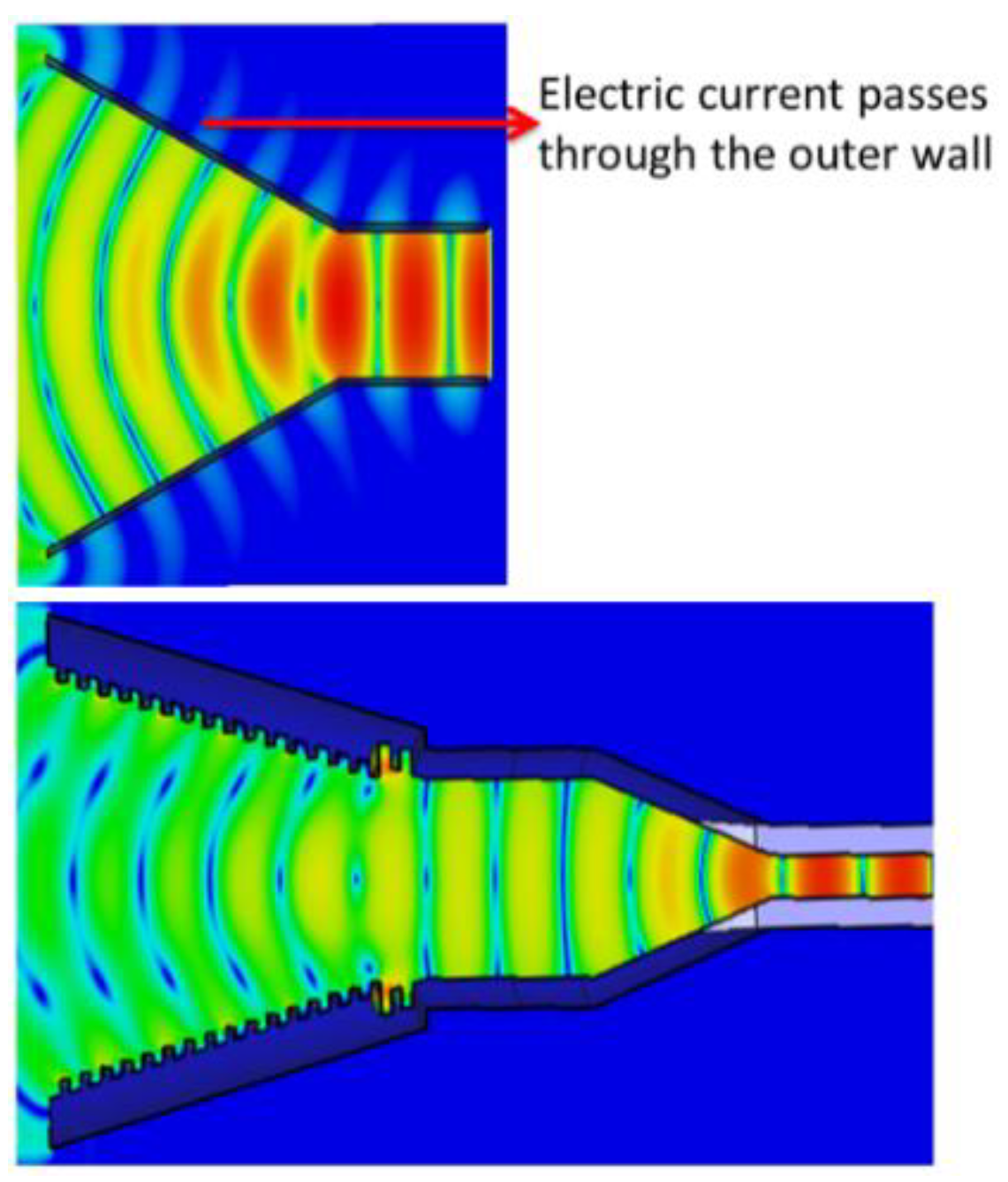
Figure 2.
Comparison of representative 3D-printed horn antenna manufacturing techniques.
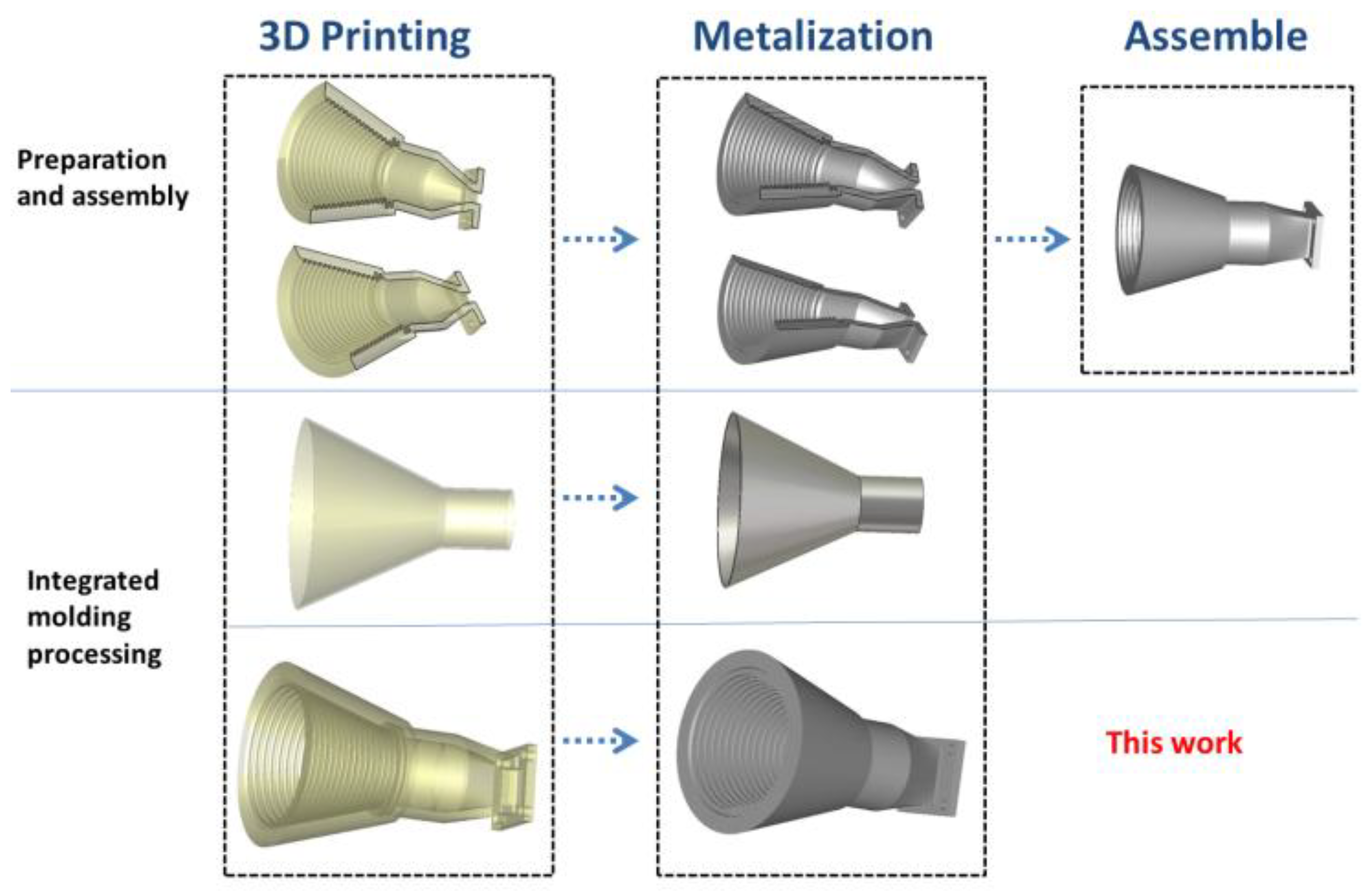
Figure 3.
Principle and process of chemical silver plating.
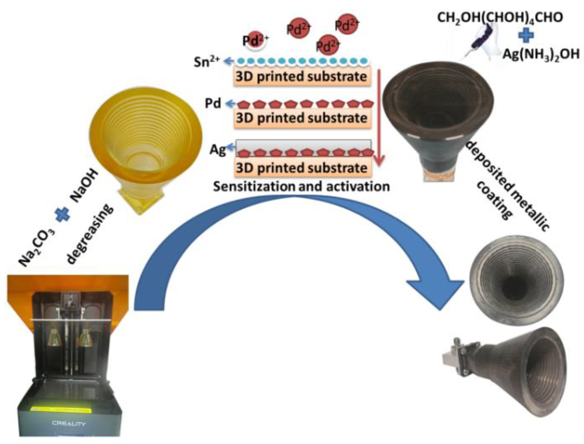
Figure 4.
Schematic diagrams of the corrugated horn structure. (a) Sectional diagram of a corrugated horn. (b) Dimensions of corrugated horn construction.
Figure 4.
Schematic diagrams of the corrugated horn structure. (a) Sectional diagram of a corrugated horn. (b) Dimensions of corrugated horn construction.
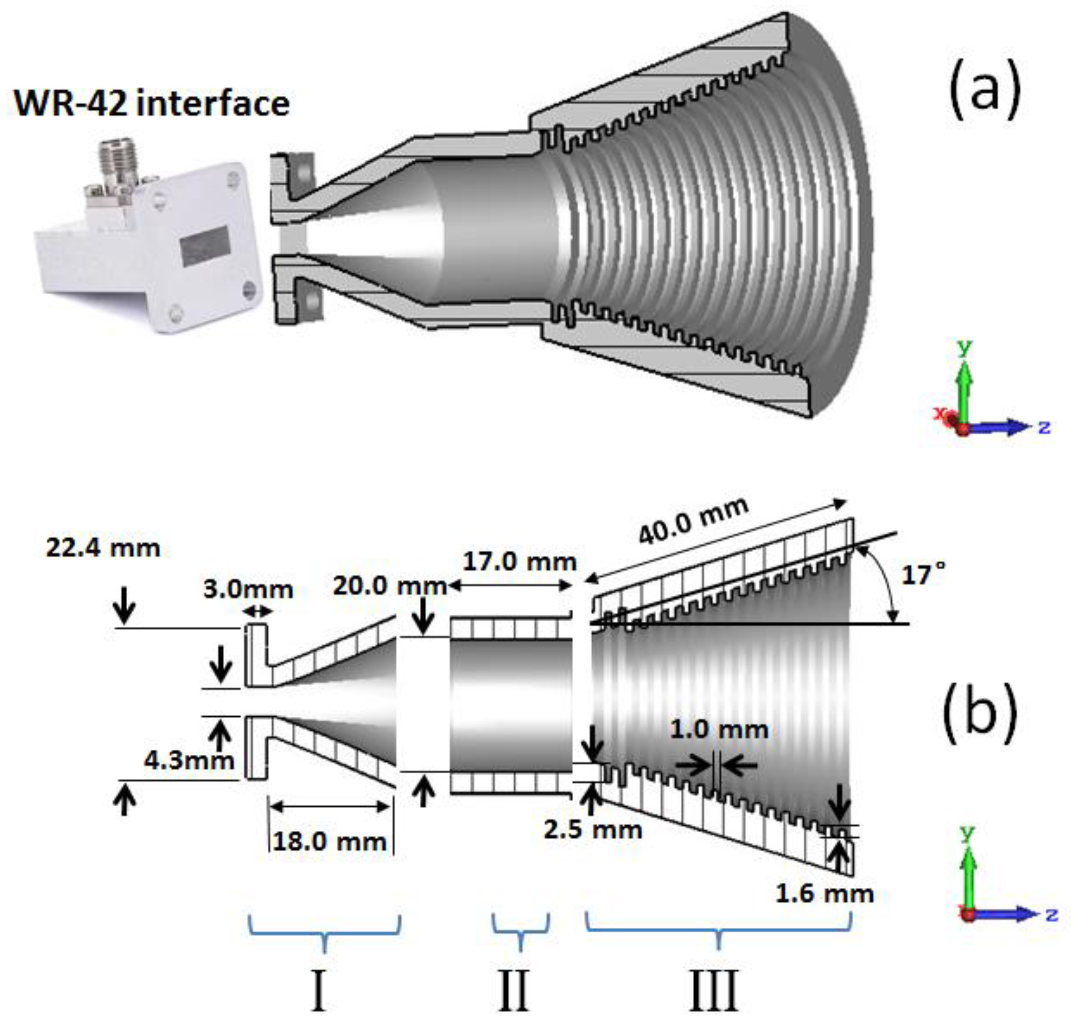
Figure 5.
Far-field antenna measurement system.
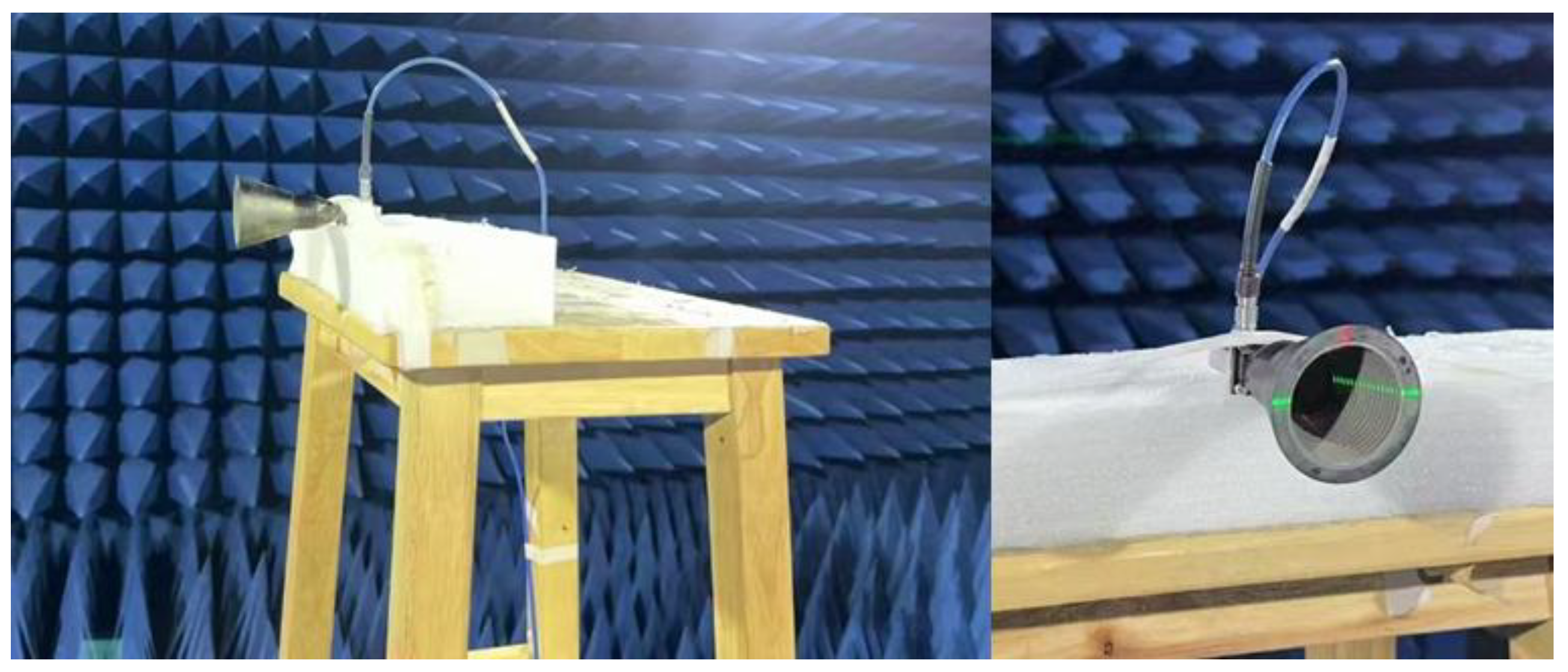
Figure 6.
(a) Photos of the fabricated corrugated horn and antenna measurement setup. (b) SEM images of the cross-section of the silver coating on the corrugated horn.
Figure 6.
(a) Photos of the fabricated corrugated horn and antenna measurement setup. (b) SEM images of the cross-section of the silver coating on the corrugated horn.
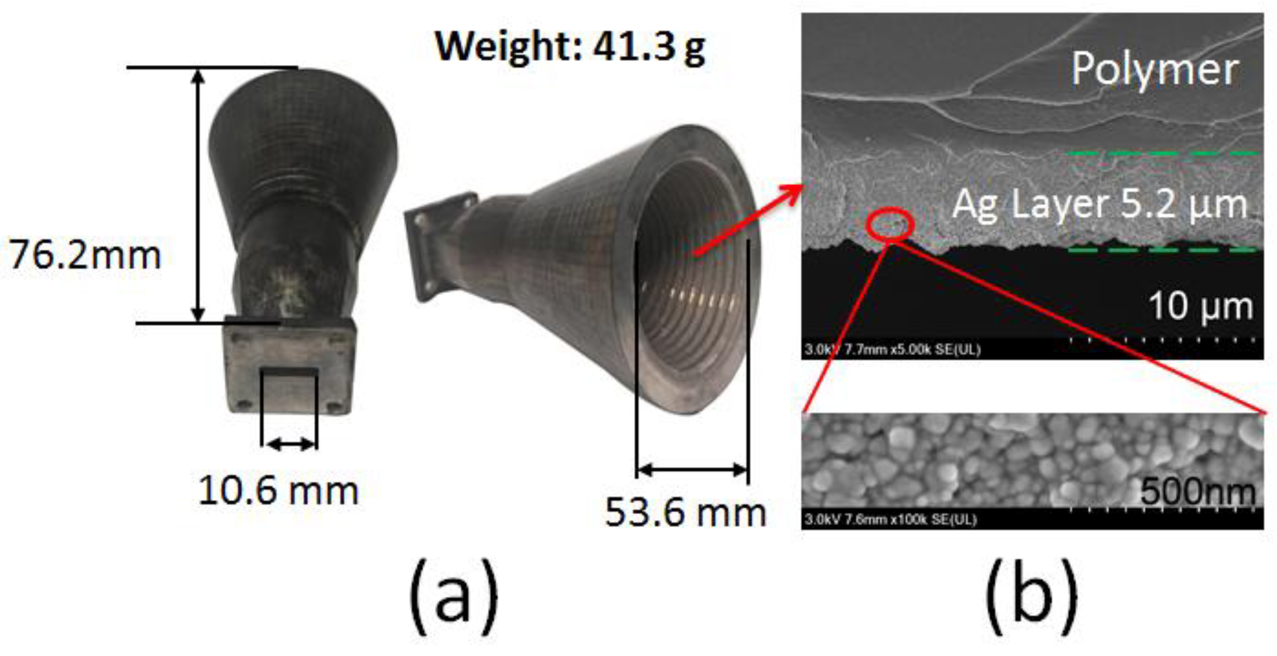
Figure 7.
(a) Simulated and measured reflection coefficient (S11) of the corrugated horn. (b) Simulated versus measured gain of the corrugated horn.
Figure 7.
(a) Simulated and measured reflection coefficient (S11) of the corrugated horn. (b) Simulated versus measured gain of the corrugated horn.
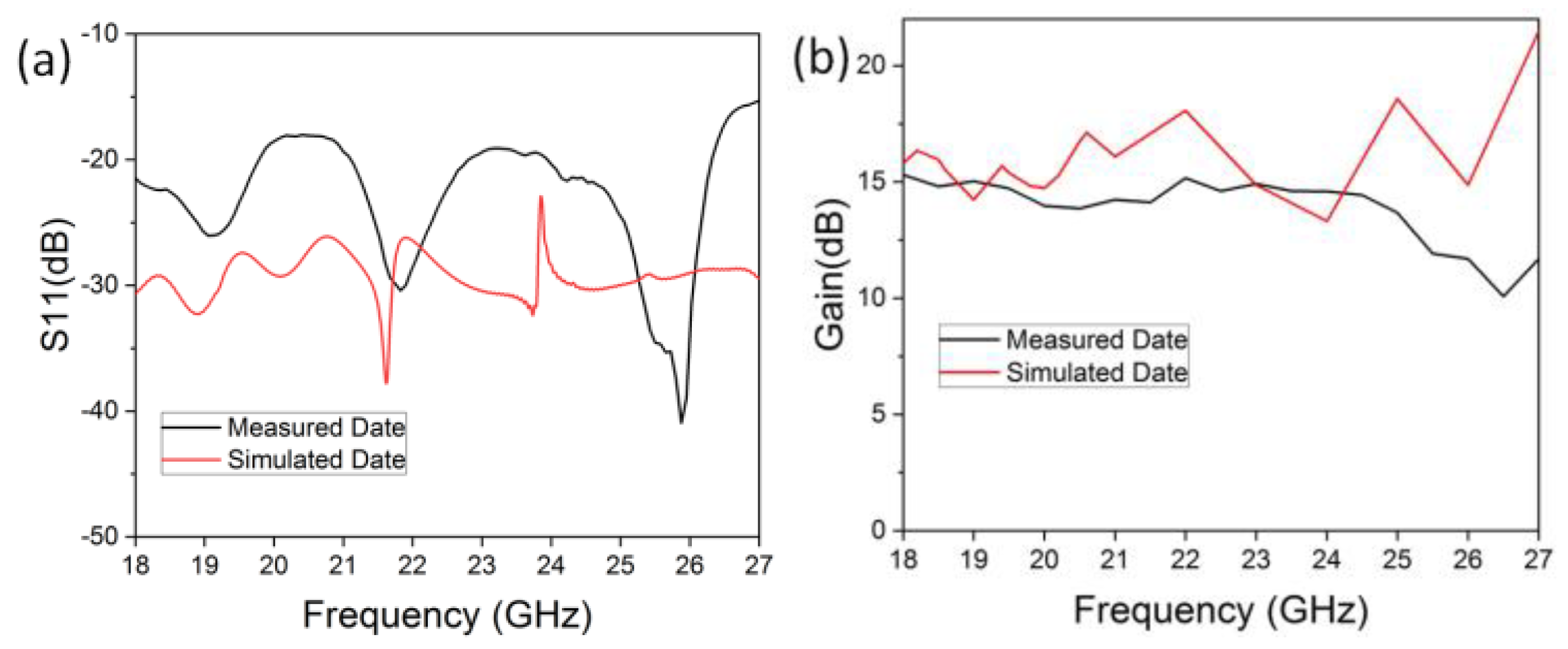
Figure 8.
(a–e) Measured versus simulated copolarized and cross-polarized radiation patterns of the E-plane and H-plane at representative frequencies from 18 to 24 GHz. The measured E-plane directivities for the presented frequencies are 15.37, 14.69, 14.11, 14.36, and 14.18 dBi, respectively.
Figure 8.
(a–e) Measured versus simulated copolarized and cross-polarized radiation patterns of the E-plane and H-plane at representative frequencies from 18 to 24 GHz. The measured E-plane directivities for the presented frequencies are 15.37, 14.69, 14.11, 14.36, and 14.18 dBi, respectively.
Disclaimer/Publisher’s Note: The statements, opinions and data contained in all publications are solely those of the individual author(s) and contributor(s) and not of MDPI and/or the editor(s). MDPI and/or the editor(s) disclaim responsibility for any injury to people or property resulting from any ideas, methods, instructions or products referred to in the content. |
© 2025 by the authors. Licensee MDPI, Basel, Switzerland. This article is an open access article distributed under the terms and conditions of the Creative Commons Attribution (CC BY) license (http://creativecommons.org/licenses/by/4.0/).
Copyright: This open access article is published under a Creative Commons CC BY 4.0 license, which permit the free download, distribution, and reuse, provided that the author and preprint are cited in any reuse.


