
Submitted:
28 February 2025
Posted:
03 March 2025
You are already at the latest version
Abstract
The use of veneer composites as structural components in engineering requires special design. The dimensioning of laminated wood can be optimized by varying the wood species, veneer thickness, orientation, arrangement, number of single layers, and other factors. Composite properties can be calculated by suitable model approaches, such as the classical laminate theory. Thus, an optimization can be achieved. The present study verifies the adaptability of the classical laminate theory for veneer composites. Native veneer, adhesive-coated veneer, and solid wood were investigated as raw materials for the plywood layers. Mechanical properties were determined by tensile and shear tests and used as parameters to calculate the composite properties of the plywood. The plywood was bending tested, and the values obtained were compared with the calculations. The best prediction of the plywood properties is obtained by using the properties of the adhesive coated veneer as a single layer.
Keywords:
veneer
; mechanical properties
; adhesive coating
; classical laminate theory
; engineering
; plywood
1. Introduction
The engineering design process requires computations to predict the mechanical behavior of components. Replacing traditional metal construction materials with wood or wood composite is a challenging task. The computation of wood and wood composites is more complex than that of traditional metal construction materials because of their anisotropic structure and properties. In addition, there are a number of factors that influence the mechanical properties of wood composites, such as climatic conditions or density. Kluge and Eichhorn have developed a computational concept for stiff jointed wood composites that allows a flexible safety concept for wood composites, enabling lightweight construction [1]. In addition to the improved computational concept, optimized dimensioning of the wood composite can have an important influence on the lightweight potential of the overall construction [2].
Veneer composites are a specific type of wood composites using veneers as the basic structure. Veneer composites can be used and optimized in the construction of technical components by purposeful dimensioning. An optimization can be reached by the orientation and arrangement of the single layers (veneers) considering the subsequent stress.
A stress-appropriate design of a laminated material requires the mechanical properties of the single layers. For veneer composites, such as plywood, the veneer is the single layer. Thus, the mechanical parameters of veneers for the fundamental stresses, such as tension, compression, and shear, are needed for the prediction of the mechanical properties of veneer composites. Hence, computation and simulation become possible.
Table 1 shows all mechanical parameters necessary for a complete veneer characterization. Because of their anatomically undefined perpendicular to fiber direction, the veneer directions are defined and indicated as perpendicular to fiber (90) and parallel to fiber (00) direction. In Table 1, available literature values are highlighted in bold [3,4,5,6]. A majority of parameters are not available in literature. In the joint project “Wood-based materials in mechanical engineering (HoMaba)”, suitable test methods for veneer characterization in tension, compression, and shear stress were developed, and complete parameter data sets for veneers were determined [7].
A veneer composite is a layered structure consisting of veneer layers that are strongly bonded by adhesive. Veneer has a porous material structure. During production, the adhesive infiltrates the material and generates a transition area in the veneer border area. It can be assumed that this transition area influences the mechanical properties of the single veneer layer.
It is well known that the veneer production leads to lathe checks in the material [8,9,10,11]. These cracks weaken the load capacity of the material. Thus, the question arises if the adhesive can repair the cracks and restore the strength of the veneer. In this case, parameters of solid wood could be used for computation and simulation.
The present study was conducted
- to clarify the influence of the adhesive on the material properties,
- to clarify the influences of the differences between the mechanical parameters of solid wood and veneers,
- to decide which parameters for the single layer (from native veneer, adhesive- coated veneer or solid wood) are suitable for the computation and simulation of the composite properties.
Classical laminate theory (CLT) is used to demonstrate predictability. This theory is an established method for calculating stiffness and stress in planar multilayer composites, developed and used mainly for fiber-reinforced plastics.
2. Materials and Methods
2.1. Single Layer
European beech (Fagus sylvatica L.) was used for the investigations. The material was taken from trunks of one habitat with comparable or equal growing conditions. The trunks have been split into two parts with the same length. One part of each trunk was used for the manufacture of rotary cut veneer with different thicknesses (1; 2 and 3 mm). The other part of each trunk was used to manufacture solid wood samples. Half of the veneers were double-sided coated with a phenol-resorcin-formaldehyde-resin adhesive (Aerodux 185, Fa. Dynea AS, Lillestrøm, Norway). The adhesive application quantity was 220 g m-² for each veneer site. The adhesive setting was conducted in a laboratory press at 90 °C and a pressure of 1 N mm-² for 120 s.
Figure 1 shows a qualitative comparison of the adhesive infiltration. The infiltration depends on the veneer depth. 1 mm thick veneers are almost completely soaked with adhesive and have a homogeneous adhesive distribution over their cross section. The thicker veneer has an area at its border with wood cells and adhesive. The center of these veneers is free of adhesive. Because of the constant amount of adhesive applied, the percentage of adhesive relative to the veneer thickness decreases.
The material parameters of native veneer (vn), adhesive coated veneer (vc), and solid wood (sw) in longitudinal – tangential direction was determined in dependence on the testing direction (00 - fiber direction, 90 - perpendicular to the fiber direction) and the sample thickness for tension and shear stress. For the strain measurement, a stereo camera system (Aramis adjustable 12M, Carl Zeiss GOM Metrology, Braunschweig, Germany) was used, which applies the principles of digital image correlation (DIC). A contrast speckle pattern was applied to the area of interest (AOI) of the sample surface.
The used testing methods for all samples are shown in Figure 2. The tension tests were conducted with rectangular samples (00-direction: 200 mm x 20 mm; 90-direction: 200 mm x 30 mm) with a universal testing machine (Inspekt 10, Hegewald & Peschke, Nossen, Germany). These dimensions were used for both the veneer and the solid wood samples, with the solid wood samples being 3 mm thick. The elastic parameters were determined in the area between 0% and 40% of the failure load. The shear tests were performed in a shear frame as described by Krüger et al. [12], which converts a uniaxial tensile load into a shear load by means of pivotally supported clamps.
With respect to the focused engineering application, all tests were conducted at a climate of 20 °C / 50% relative humidity [1]. 20 replicates for each material and thickness were tested in tension parallel to the fiber (00), perpendicular to the fiber (90), and shear. Table 2 shows the density and the moisture content of the samples tested.
2.2. Plywood
Plywood with different veneer thicknesses and number of plies was produced to compare the composite properties, which were later calculated using the characteristic values of the single layers. The plywood was produced at a laboratory press with veneers and adhesive of the same batch as the single veneer layers. The amount of adhesive applied to each veneer layer was 450 g m-2. The board was pressed in a position-controlled manner, resulting in 10% compression of the veneers, at a temperature of 90 °C and a pressing time of 60 min. After pressing, the boards were stacked, weighed, and conditioned for two weeks. The composition of the plywood is shown in Table 3.Figure 3 shows an example of cross sections of plywood made from 1 mm and 2 mm veneers and gives an impression of the different adhesive distribution (dark areas) throughout the cross section.
Bending is a common load case in practice and combines the basic stresses of tension and shear simultaneously. For this reason, material tests were conducted under 3 - point bending loading in accordance with DIN EN 310 [13]. The schematic test setup, including the sample dimensions, is shown in Figure 4.
In contrast to the rectangular samples suggested by DIN EN 310 [13], a square cross section was used, with reference to DIN 52186 [14]. This made it possible to use the same test setup and sample dimensions for both plate bending (force applied in the thickness direction of the plywood) and disk bending (force applied in the plane of the layers). Pre-investigations have shown that the sample width does not affect the strength and failure behavior of the tested plywoods. In addition to measuring the strain in accordance with the standard, the outer fiber strain was measured directly at the bottom side of the sample using the optical 3D measurement system. The advantage is that the calculation of the outer fiber strain by using the deflection could be omitted. Furthermore, the elastic shear properties were measured on a defined measuring area on the front side of the sample according to DIN EN 408 [15]. Simultaneous measurement of the front and the bottom side of the sample was achieved by orienting the optical measurement system at a 45° angle to both measurement areas (Figure 4).
Similar to the single layer tests, all tests were conducted at 20 °C and 50% relative humidity. For each plywood and test direction, 20 replicates were tested.
3. Results and Discussion
3.1. Single Layer
Figure 5 exemplarily shows a comparison of Young’s modulus and tensile strength. Results are shown for both test directions and for different material thicknesses of single layers.
The results show a reduction in mechanical parameters with increasing veneer thickness, mainly perpendicular to the fiber direction (90-direction). In addition, the anisotropy of the material increases with increasing veneer thickness. These facts are caused by the lathe checks in the veneer. The checks create a notch stress in their base, which acts as a breaking point in the veneer cross section. Lathe checks also cause a slight decrease in parameters in the fiber direction. Adhesive coating leads to a clear increase in the parameters compared to the parameters of the native veneer, some of which are higher than those of the solid wood samples. The increase in the parameters of the adhesive coated samples decreases with increasing veneer thickness due to the percentage decrease and the different infiltration of the adhesive into the veneer cross section.
Adhesive coated samples show higher strength than solid wood samples in the 00-direction. The adhesive infiltrates and fills the cell lumen, inhibiting the ability to elongate. It also homogenizes the veneer surface. This reduces stress peaks and provides a more homogeneous stress distribution across the cross section. Perpendicular to the fiber direction, the strength of the adhesive coated samples is lower than that of solid wood. This is due to the embrittlement of the material behavior caused by the adhesive and is evident from the obviously higher Young’s modulus compared to solid wood. Therefore, the adhesive coated veneer samples failed at lower strains than the solid wood samples. In addition, the lathe checks in the veneer, which are partially filled with adhesive, lead to a reduction in strength. This proportion decreases with increasing veneer thickness so that the strength of the adhesive-coated veneers approaches that of the native veneers.
3.2. Plywood
Classical laminate theory has been used as a computational model to predict the behavior of veneer composites [16,17,18]. Mittelstedt and Becker provide a detailed description of the use of CLT [19]. Further detailed information and example calculations are provided in Appendix A.
For the plate bending, the plate stiffnesses of the laminate stiffness matrix are decisive, while for the disk bending, the membrane stiffnesses are used for the calculation of the engineering constants (E, G). To calculate the composite parameters, the data sets of native veneers (vn), adhesive coated veneers (vc), and solid wood (sw) were used and compared.
The box plots in Figure 6 show the comparison of the elastic composite parameters (Young’s modulus and shear modulus), determined in the 3-point bending test, with the calculated parameters using the single layer parameters (displayed as dots). The shear modulus of the plate bending could not be calculated because the CLT requires plane stress without any thickness properties. Therefore, a difference between the model (CLT) and the reality has to be stated.
The diagrams (Figure 6) show a difference between the plywood variants in both the measured and the calculated parameters, depending on the single layer thickness and the number of layers. The lowest Young’s modulus was determined for ply2, which consists of 2 mm thick veneers. This is due to the lower density compared to the 1 mm and 3 mm thick veneers (see Table 2). The lower density is also reflected in the calculated Young’s modulus of ply2 with vn and vc. Overall, the calculated parameters E and G based on the adhesive coated veneers show the best agreement with the measured values. The parameters based on vn show the greatest difference to the measured values. The evaluation of the solid wood parameters for the single layer must be differentiated. The difference between model and experimental data decreases with the decreasing number of layers. Due to the strong anisotropy of the material, the properties of the composite are largely determined by the fiber direction of the single layers. As the number of layers decreases, the relative proportion of single layers running in fiber direction increases (ply1=52%, ply2=55%, ply3=57%). The differences between vc and sw are mainly in the 90-direction. The results therefore converge in such a way that ply3 shows the lowest differences between vc and sw when they used as a single layer input.
4. Conclusion
In principle, the mechanical parameters of solid wood and veneer are different due to the presence of lathe checks in veneer. They decisively influence the properties in the 90-direction and act as a breaking point. In the 00-direction, the influence of the lathe checks on the parameters is minor. The difference between the parameters of solid wood and veneer is therefore small.
The adhesive coating of the veneer results in a clear increase in the mechanical parameters compared to the native veneer. This increase depends on a number of factors (e.g., adhesive system, application rate, veneer thickness, fiber direction). For a constant adhesive application rate, the increase in parameters decreases with increasing veneer thickness. The influence of the adhesive coating is greater in the 90-direction than in the fiber direction (00-direction).
To estimate the parameters of a veneer composite from the parameters of the single layers, the mechanical parameters of adhesive coated veneer (coated with the same adhesive and using the same veneer thickness as for the composite) are the most appropriate parameters. If these parameters are not available, solid wood parameters can be used for veneer composites based on veneers thicker than 3 mm and with a small number of layers (n ≤ 7).
Author Contributions
Conceptualization, R.K.; methodology, R.K. and B.B.; software, R.K.; validation, R.K. and B.B.; formal analysis, R.K.; investigation, R.K. and B.B.; resources, R.K.; data curation, R.K.; writing—original draft preparation, R.K. and B.B.; writing—review and editing, A.W. and M.Z.; visualization, R.K. and B.B.; supervision, A.W.; project administration, M.Z. and B.B.; funding acquisition, M.Z. All authors have read and agreed to the published version of the manuscript.
Funding
The research project “Wood-based materials in mechanical engineering (HoMaba)”, on which this publication is based on, was funded by the German Federal Ministry of Food and Agriculture (funding reference 22003818). The project was a joint project of following research partners: TU of Munich, Fraunhofer Institute of Wood Research WKI, University of Technology Chemnitz, Eberswalde University of Sustainable Development, University of Göttingen and the Technical University of Applied Science Rosenheim.
Data Availability Statement
Data are available upon request from the corresponding author.
Acknowledgments
The authors are grateful to the staff of Eberswalde University of Sustainable Development and Fraunhofer Institute of Wood Research WKI for obtaining and providing the veneer and plywood materials.
Conflicts of Interest
The authors declare no conflicts of interest.
Appendix A
The following describes the calculation of laminate’s effective properties using the Classical Laminate Theory [19].
The single layer of the laminate (ply) has the following known properties:
- thickness and
- material properties .
The following parameters are calculated successively to obtain the laminate’s effective properties.
Reduced stiffness matrix for an orthotropic layer:
Transformation of the reduced stiffnesses depending on the fiber angle for each ply related to the main orientations in the composite:
Coordinates of a ply no. (see Figure A1):
Figure A1.
cross section of the laminate.
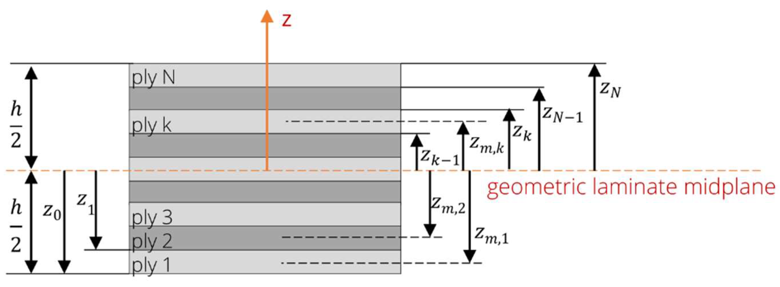
ABD matrix of a symmetrical, orthotropic cross-ply laminate (0°/90° stacking):
is called the extensional stiffness matrix related the normal and shear stresses, is the coupling stiffness matrix and is the bending stiffness matrix. and is defined as:
Effective laminate elastic engineering constants can be calculated by using :
Effective laminate flexural elastic engineering constants can be calculated by using :
Table A1 shows an example of the calculation of the effective properties of a 21-layer plywood using the properties of a 1mm coated veneer.

Table A1.
Example calculation of laminate effective properties using classical laminate theory.
| single layer | material: | 1 mm veneer, coated | ||||||||
| thickness tk: | 0.91 | mm | ||||||||
| E00 = | 15696 | MPa | ||||||||
| E90 = | 2168 | MPa | ||||||||
| µ0090 = | 0.44 | |||||||||
| G = | 903 | MPa | ||||||||
| stacking | no. | θ | tk | zm.k | Q11 | Q12 | Q22 | Q66 | zk-zk-1 | zk³-zk-1³ |
| 1 | 0 | 0.91 | -9.1 | 16127 | 980 | 2228 | 903 | 0.91 | 226.3 | |
| 2 | 90 | 0.91 | -8.19 | 2228 | 980 | 16127 | 903 | 0.91 | 183.3 | |
| 3 | 0 | 0.91 | -7.28 | 16127 | 980 | 2228 | 903 | 0.91 | 144.9 | |
| 4 | 90 | 0.91 | -6.37 | 2228 | 980 | 16127 | 903 | 0.91 | 111.0 | |
| 5 | 0 | 0.91 | -5.46 | 16127 | 980 | 2228 | 903 | 0.91 | 81.6 | |
| 6 | 90 | 0.91 | -4.55 | 2228 | 980 | 16127 | 903 | 0.91 | 56.7 | |
| 7 | 0 | 0.91 | -3.64 | 16127 | 980 | 2228 | 903 | 0.91 | 36.4 | |
| 8 | 90 | 0.91 | -2.73 | 2228 | 980 | 16127 | 903 | 0.91 | 20.6 | |
| 9 | 0 | 0.91 | -1.82 | 16127 | 980 | 2228 | 903 | 0.91 | 9.3 | |
| 10 | 90 | 0.91 | -0.91 | 2228 | 980 | 16127 | 903 | 0.91 | 2.5 | |
| 11 | 0 | 0.91 | 0 | 16127 | 980 | 2228 | 903 | 0.91 | 0.2 | |
| 12 | 90 | 0.91 | 0.91 | 2228 | 980 | 16127 | 903 | 0.91 | 2.5 | |
| 13 | 0 | 0.91 | 1.82 | 16127 | 980 | 2228 | 903 | 0.91 | 9.3 | |
| 14 | 90 | 0.91 | 2.73 | 2228 | 980 | 16127 | 903 | 0.91 | 20.6 | |
| 15 | 0 | 0.91 | 3.64 | 16127 | 980 | 2228 | 903 | 0.91 | 36.4 | |
| 16 | 90 | 0.91 | 4.55 | 2228 | 980 | 16127 | 903 | 0.91 | 56.7 | |
| 17 | 0 | 0.91 | 5.46 | 16127 | 980 | 2228 | 903 | 0.91 | 81.6 | |
| 18 | 90 | 0.91 | 6.37 | 2228 | 980 | 16127 | 903 | 0.91 | 111.0 | |
| 19 | 0 | 0.91 | 7.28 | 16127 | 980 | 2228 | 903 | 0.91 | 144.9 | |
| 20 | 90 | 0.91 | 8.19 | 2228 | 980 | 16127 | 903 | 0.91 | 183.3 | |
| 21 | 0 | 0.91 | 9.1 | 16127 | 980 | 2228 | 903 | 0.91 | 226.3 | |
| composite | ||||||||||
| thickness h = | 19.11 | mm | ||||||||
| Effective laminate elastic engineering constants | ||||||||||
| E11 = | 9400 | MPa | µ12 = | 0.11 | ||||||
| E22 = | 8745 | MPa | G12 = | 903 | MPa | |||||
| Effective laminate flexural elastic engineering constants | ||||||||||
| E11.f = | 10056 | MPa | µ12.f = | 0.12 | ||||||
| E22.f = | 8096 | MPa | G12.f = | 903 | MPa | |||||
References
- Kluge, P.; Eichhorn, S. Calculation Concept for Wood-Based Components in Mechanical Engineering. Adv. Eng. Mater. 2023, 25, 2300085. [Google Scholar] [CrossRef]
- Krüger, R. Untersuchungen an Rotbuchenschälfurnier zur Anwendung furnierbasierter Werkstoffe im. Maschinenbau. Dissertation, Technische Universität Dresden, Dresden, 2022. [Google Scholar] [CrossRef]
- Bellair, B. Beschreibung des anisotropen Materialverhaltens von Rotbuchenfurnier als Basis für rechnergestützte Umformsimulationen 2013, Shaker, Aachen.
- Buchelt, B.; Wagenführ, A. The mechanical behaviour of veneer subjected to bending and tensile loads. Holz Roh Werkst 2008, 66, 289–294. [Google Scholar] [CrossRef]
- Pfriem, A.; Buchelt, B. Influence of the slicing technique on mechanical properties of the produced veneer. Eur J Wood Prod 2011, 69, 93–99. [Google Scholar] [CrossRef]
- Krüger, R.; Buchelt, B.; Wagenführ, A. Method for determination of beech veneer behavior under compressive load using the short-span compression test. Wood Sci Technol 2023, 57, 1125–1138. [Google Scholar] [CrossRef]
- Engelhardt, M.; Khaloian Sarnaghi, A.; Buchelt, B.; Krüger, R.; Schulz, T.; Gecks, J. Holzbasierte Werkstoffe im Maschinenbau (HoMaba) - Berechnungskonzepte, Kennwertanforderungen, Kennwertermittlung. 2022. [CrossRef]
- Pałubicki, B.; Marchal, R.; Butaud, J.-C.; Denaud, L.-E.; Bléron, L.; Collet, R.; Kowaluk, G. A Method of Lathe Checks Measurement; SMOF device and its software. Eur J Wood Prod 2010, 68, 151–159. [Google Scholar] [CrossRef]
- Buchelt, B.; Wagenführ, A.; Dietzel, A.; Raßbach, H. Quantification of cracks and cross-section weakening in sliced veneers. Eur J Wood Prod 2018, 76, 381–384. [Google Scholar] [CrossRef]
- Rohumaa, A.; Viguier, J.; Girardon, S.; Krebs, M.; Denaud, L. Lathe check development and properties: effect of log soaking temperature, compression rate, cutting radius and cutting speed during peeling process of European beech (Fagus sylvatica L.) veneer. Eur J Wood Prod 2018, 76, 1653–1661. [Google Scholar] [CrossRef]
- Pot, G.; Denaud, L.-E.; Collet, R. Numerical study of the influence of veneer lathe checks on the elastic mechanical properties of laminated veneer lumber (LVL) made of beech. Holzforschung 2015, 69, 337–345. [Google Scholar] [CrossRef]
- Krüger, R.; Buchelt, B.; Wagenführ, A. New method for determination of shear properties of wood. Wood Sci Technol 2018, 52, 1555–1568. [Google Scholar] [CrossRef]
- European Comitee for Standardization. Wood-based panels; determination of modulus of elasticity in bending and of bending strength; German version EN 310:1993.
- German Institute for Standardization. DIN 52186 Prüfung von Holz; Biegeversuch, Beuth Verlag GmbH 1978.
- European Comitee for Standardization. Timber structures - Structural timber and glued laminated timber - Determination of some physical and mechanical properties (includes Amendment A1:2012); EN 408:2012.
- Merhar, M. Determination of Elastic Properties of Beech Plywood by Analytical, Experimental and Numerical Methods. Forests 2020, 11, 1221. [Google Scholar] [CrossRef]
- Weight, S.; Yadama, V. Manufacture of laminated strand veneer (LSV) composite. Part 2: Elastic and strength properties of laminate of thin strand veneers. Holzforschung, 2008, 62, 725–730. [Google Scholar] [CrossRef]
- Chen, A.; Liang, Y.; Jiang, Z.; Sun, J. Prediction of elastic modulus and mid-span deflection of bamboo-wood composite laminates. BioResources 2021, 16, 7784–7798. [Google Scholar] [CrossRef]
- Mittelstedt, C.; Becker, W. Strukturmechanik ebener Laminate. Studienbereich Mechanik, Technische Universität Darmstadt, Darmstadt, Germany, 2016.
Figure 1.
Qualitative comparison of the adhesive infiltration (black) in dependence on the veneer thickness: 1 mm (left); 2 mm (middle); 3 mm (right).
Figure 1.
Qualitative comparison of the adhesive infiltration (black) in dependence on the veneer thickness: 1 mm (left); 2 mm (middle); 3 mm (right).
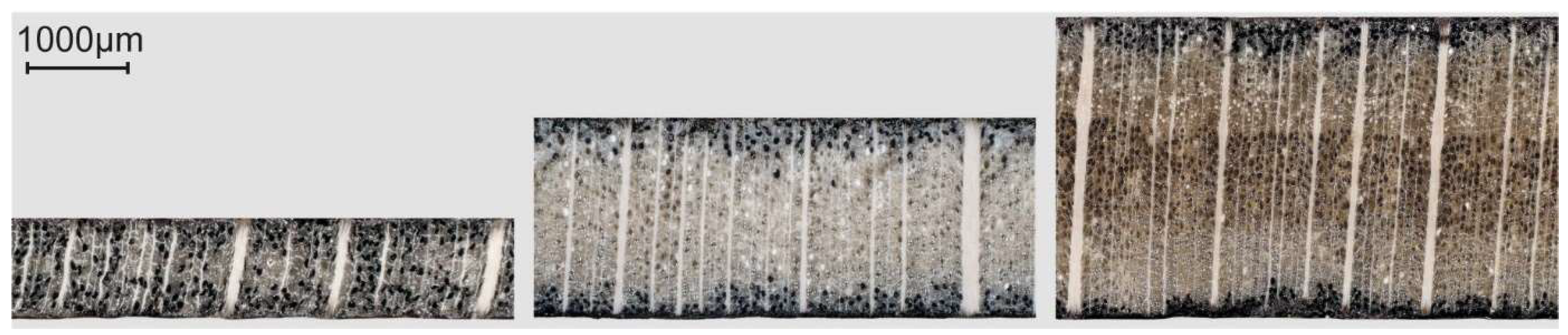
Figure 2.
single layer testing methods; a) tension and b) shear.
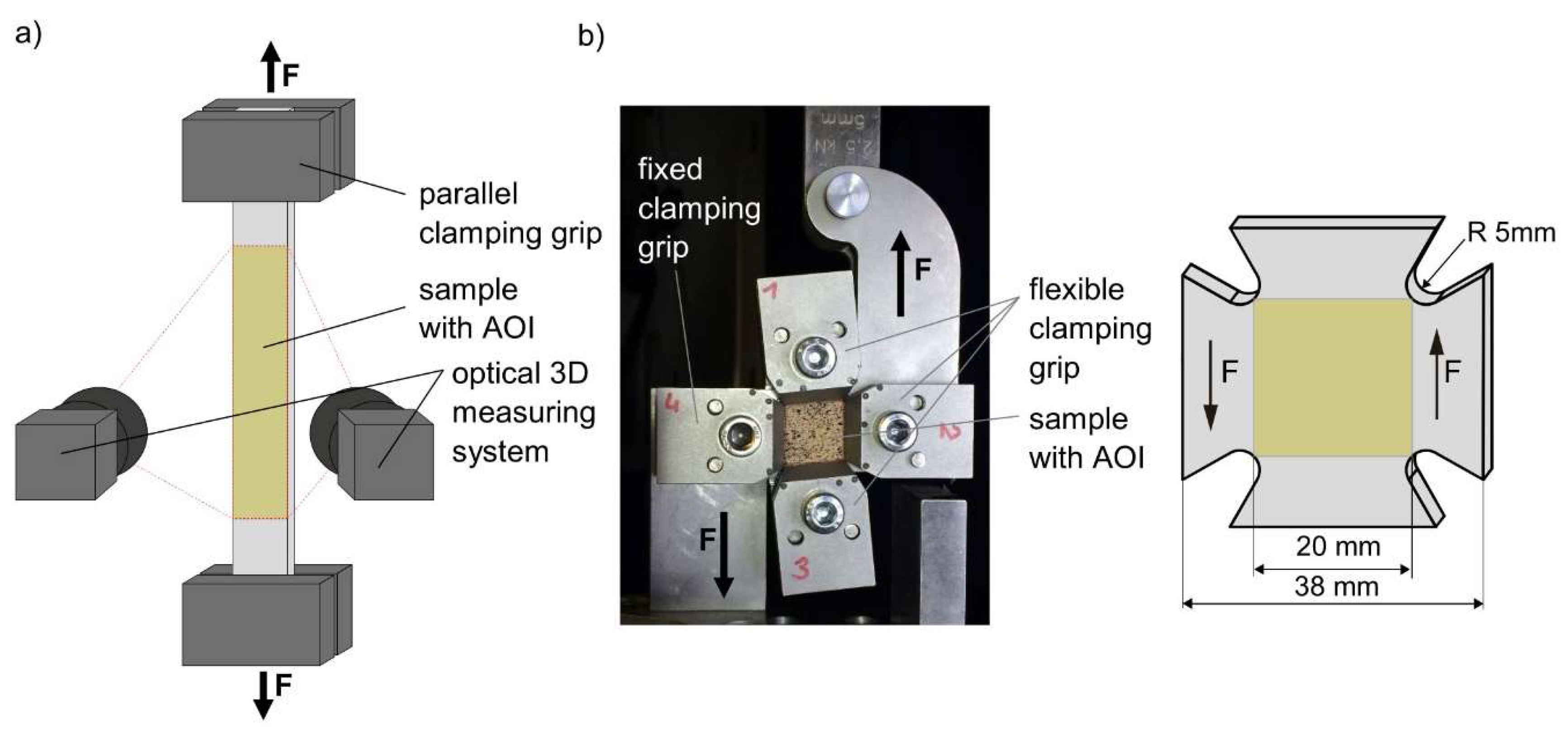
Figure 3.
Microscopy of the plywood cross-section of 1mm (left) and 2mm veneer layers (right).
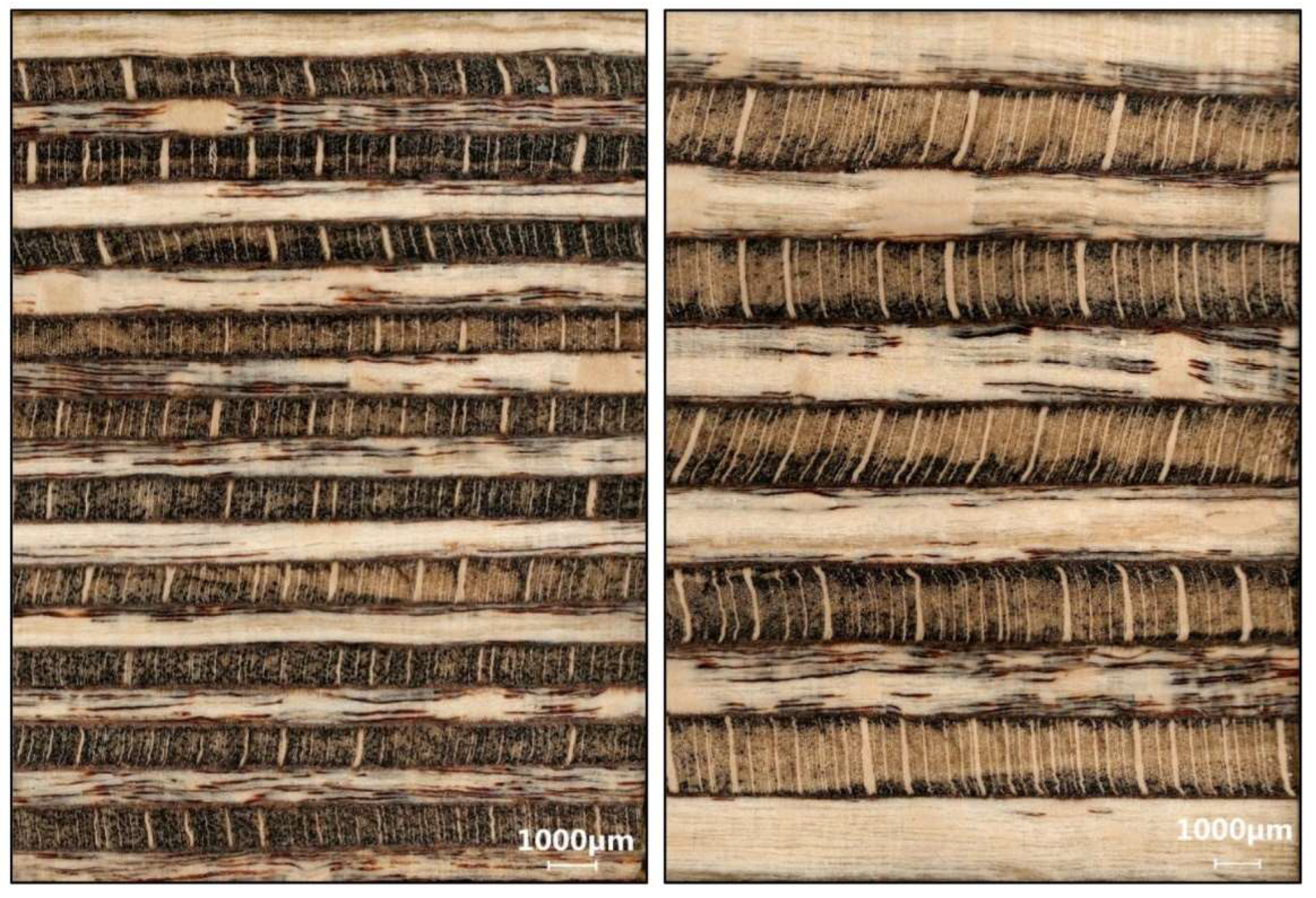
Figure 4.
Schematic test setup of 3 - point bending test including optical measurement system at 45° angle.
Figure 4.
Schematic test setup of 3 - point bending test including optical measurement system at 45° angle.
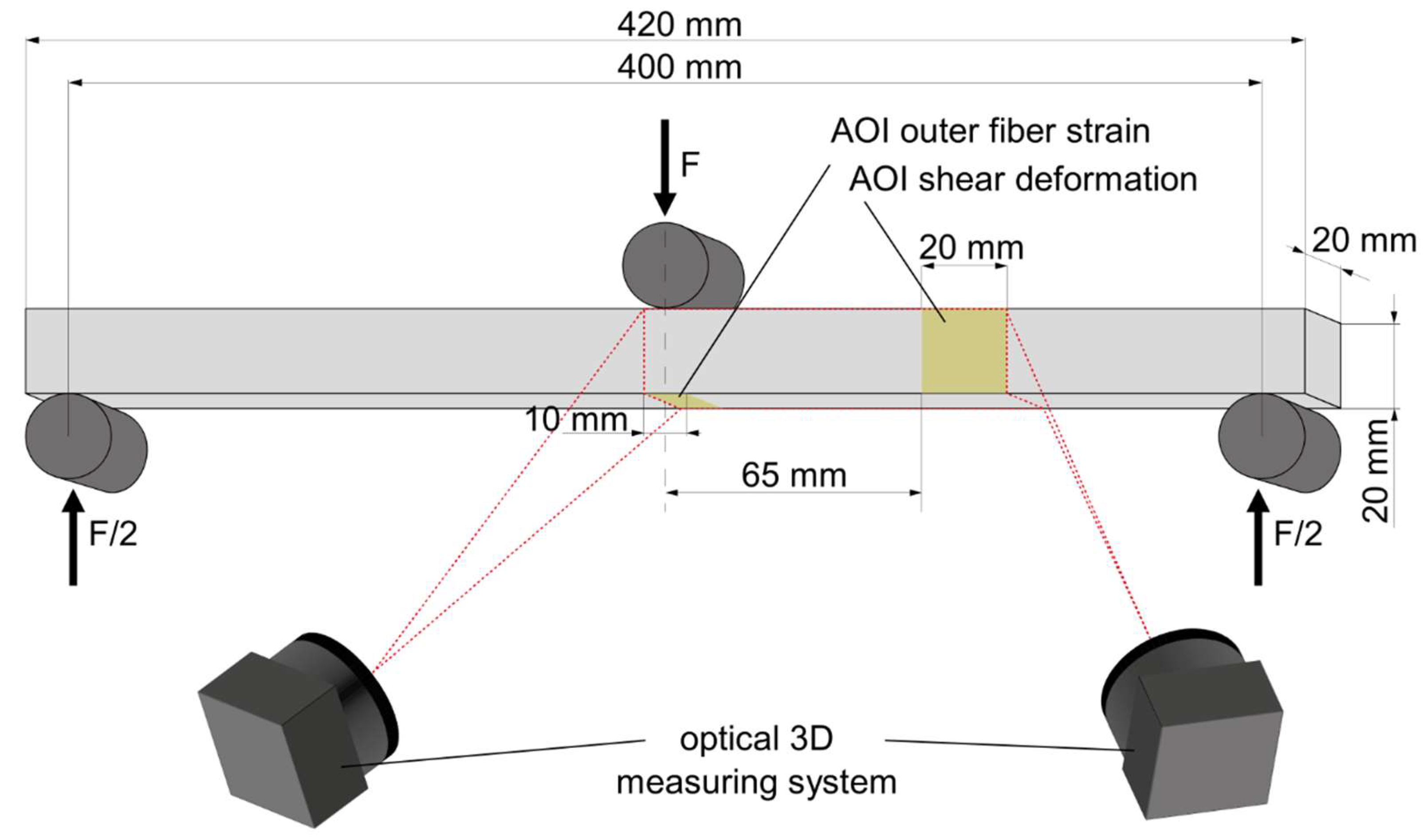
Figure 5.
Tension test properties for veneer (vn), adhesive coated veneer (vc), and solid wood (sw) in dependence on material thickness and test direction.
Figure 5.
Tension test properties for veneer (vn), adhesive coated veneer (vc), and solid wood (sw) in dependence on material thickness and test direction.
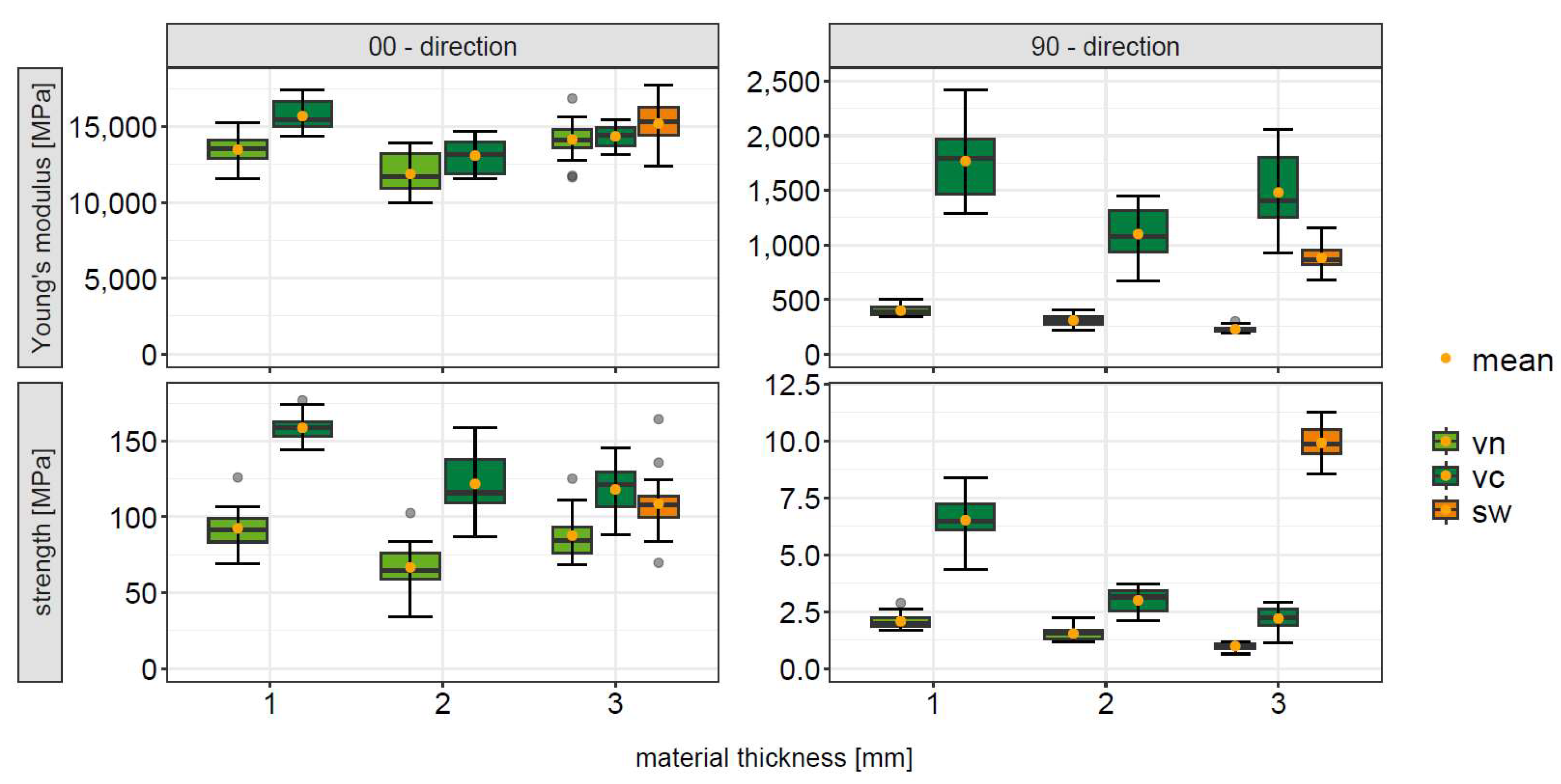
Figure 6.
Comparison of experimental data (box plots) with the calculated composite properties (displayed as dots) for 3 – point bending; vn – native veneer, vc - adhesive coated veneer, sw – solid wood.
Figure 6.
Comparison of experimental data (box plots) with the calculated composite properties (displayed as dots) for 3 – point bending; vn – native veneer, vc - adhesive coated veneer, sw – solid wood.
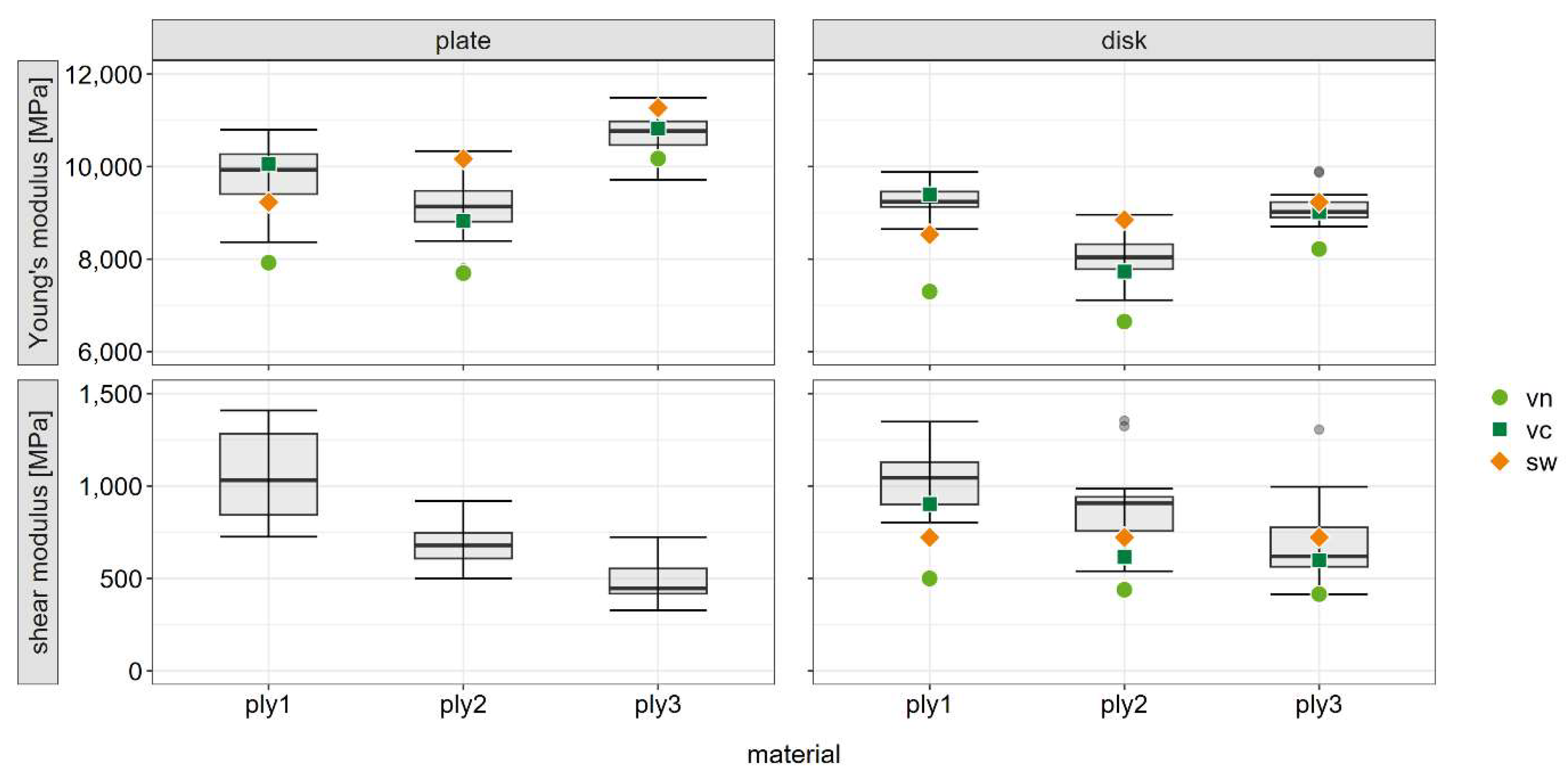
Table 1.
Essential parameters for a material model based on veneer. Available parameters are highlighted in bold.
Table 1.
Essential parameters for a material model based on veneer. Available parameters are highlighted in bold.
| Stress | Engineering constant | Failure strain | Strength |
| tension | E00, E90, µ | ε00, ε90 | σ00, σ90 |
| compression | E00, E90, µ | ε00,ε90 | σ00,σ90 |
| shear | G | γ | τ |
E … Young’s modulus; µ … Poisson’s ratio; ε … strain; σ … strength; G … shear modulus; γ … shear strain; τ … shear strength.
Table 2.
Density and moisture content of single layer material.
| material | thickness | density | moisture content |
| veneer | 1 mm | 613 kg m-3 | 9.4% |
| 2 mm | 530 kg m-3 | 9% | |
| 3 mm | 636 kg m-3 | 8.4% | |
| veneer coated | 1 mm | 918 kg m-3 | 8.4% |
| 2 mm | 741 kg m-3 | 9.2% | |
| 3 mm | 708 kg m-3 | 9.2% | |
| solid wood | 3 mm | 692 kg m-3 | 9% |
Table 3.
Structure of the investigated plywood.
| material | no. of layers | layer thickness | thickness | density | moisture content |
| plywood 1 | 21 | 1 mm | 19.2 mm | 1075 kg m-3 | 8.8% |
| plywood 2 | 11 | 2 mm | 20.3 mm | 826 kg m-3 | 9% |
| plywood 3 | 7 | 3 mm | 19.4 mm | 818 kg m-3 | 9% |
Table 4.
Tension properties, mean values.
| material | thickness | load direction | Young’s modulus | Poisson’s ratio | strength | failure strain |
| veneer | 1 mm | 0° | 13488 MPa | 0.47 | 93 MPa | 0.7% |
| 90° | 398 MPa | 0.03 | 2.1 MPa | 0.6% | ||
| 2 mm | 0° | 11870 MPa | 0.46 | 65 MPa | 0.6% | |
| 90° | 309 MPa | 0.03 | 1.5 MPa | 0.5% | ||
| 3 mm | 0° | 14156 MPa | 0.50 | 88 MPa | 0.7% | |
| 90° | 227 MPa | 0.02 | 1 MPa | 0.4% | ||
| veneer coated | 1 mm | 0° | 15696 MPa | 0.44 | 161 MPa | 1.1% |
| 90° | 2168 MPa | 0.05 | 6.5 MPa | 0.4% | ||
| 2 mm | 0° | 13085 MPa | 0.45 | 122 MPa | 1% | |
| 90° | 1100 MPa | 0.04 | 3 MPa | 0.3% | ||
| 3 mm | 0° | 14355 MPa | 0.48 | 118 MPa | 0.9% | |
| 90° | 1553 MPa | 0.04 | 2.2 MPa | 0.2% | ||
| solid wood | 3 mm | 0° | 15354 MPa | 0.43 | 109 MPa | 0.8% |
| 90° | 880 MPa | 0.03 | 10 MPa | 1.5% |
Table 5.
Shear properties, mean values.
| material | thickness | shear modulus | strength | failure strain |
| veneer | 1 mm | 500 MPa | 9.9 MPa | 0.031 |
| 2 mm | 439 MPa | 9.2 MPa | 0.031 | |
| 3 mm | 415 MPa | 7.3 MPa | 0.024 | |
| veneer coated | 1 mm | 903 MPa | 24.5 MPa | 0.056 |
| 2 mm | 615 MPa | 15.4 MPa | 0.045 | |
| 3 mm | 598 MPa | 12.9 MPa | 0.036 | |
| solid wood | 3 mm | 722 MPa | 18.2 MPa | 0.050 |
Disclaimer/Publisher’s Note: The statements, opinions and data contained in all publications are solely those of the individual author(s) and contributor(s) and not of MDPI and/or the editor(s). MDPI and/or the editor(s) disclaim responsibility for any injury to people or property resulting from any ideas, methods, instructions or products referred to in the content. |
© 2025 by the authors. Licensee MDPI, Basel, Switzerland. This article is an open access article distributed under the terms and conditions of the Creative Commons Attribution (CC BY) license (http://creativecommons.org/licenses/by/4.0/).
Copyright: This open access article is published under a Creative Commons CC BY 4.0 license, which permit the free download, distribution, and reuse, provided that the author and preprint are cited in any reuse.


