1. Introduction: State of Art
To carry out various calculations, during the design of the vessel or its operation, it is necessary to have information about the values of the accelerations acting on this floating object. Such information is necessary for strength calculations of ship hull elements and securing devices for cargo. There are various recommendations on this issue, but there is no single approach. This especially applies to the values of horizontal longitudinal accelerations.
For the passenger ships some parameters can be obtained by the NORDFORSK 1987 criterion, but mainly referring to vertical accelerations and transversal, less attention is given to the longitudinal acceleration, mainly due to the different kind of accommodations. In the cargo ships, as opposite, all the accelerations along the 3-axis can provide stresses on the security devices, also considering the consequences of a failure of security devices, with consequences as the movements of loads, leading to serious damages of the loss of the ship due to sudden capsizing as consequence of unexpected movements of loads. Surely, at a first look, this problem could be considered limited to only transversal accelerations and transversal movements of load, but his obviously an underestimations of the problem, because also longitudinal accelerations can cause the failure of the safety devices causing a random movement of loads. The article aims at providing a robust, user friendly, method to evaluate the accelerations and consequentially define the stresses on structures and security devices.
The Code of Safe Practice for Cargo Stowage and Securing (CSS Code) [
1] provides information on transverse, vertical and longitudinal accelerations occurring during operation,
Table 1.
When receiving this information, the experience of year-round operation of a vessel with a length of 100 m, in an unlimited navigation area, at a speed of 15 knots was used. For operation in limited areas, it is suggested to use coefficients that take into account the season and wave height. The acceleration values were calculated according to the resolution formulas of MSC.5(48) [
2].
The reduction factor may be used for significant wave heights not exceeding 12 m for the design of anchorages in any of the following cases:
1. The required anchorage is calculated for the maximum expected twenty-year significant wave height in the limited area.
2. The maximum significant wave height that a particular system can withstand is calculated and the vessel is limited to operating only in significant wave height up to the calculated maximum.
3. The required fastening mechanisms shall be designed for different significant wave heights and the arrangement shall be selected according to the maximum expected wave height for each voyage for which an accurate weather forecast is available. Thus, the duration of voyage should not exceed 72 hours or the duration accepted by the Administration.
From the consideration of the reduction coefficient formula , it can be concluded that for calculations, for limited areas, it is possible to use the height of a significant wave equal to 12 m and less.
Resolution MSC.5(48) [
2] suggests the following way of calculating longitudinal accelerations.
where:
;
L0- the length of the vessel;
cB- block coefficient;
;
z- vertical distance from the waterline to the centre of gravity of the tank (positive value above the waterline)
In a modern article [
3], the differential equation of the motion of a ship on a wave is considered, but there are no recommendations on the value of longitudinal accelerations.
The authors of the paper [
4] reviewed most of the existing methods for calculating additional water resistance when a vessel meets a wave, but did not give recommendations for calculating longitudinal accelerations.
Article [
5] contains interesting information about the behaviour of the vessel when moving towards the wave, data on pressure values, for calculating slamming. There are no recommendations on the values of longitudinal accelerations in the article.
The development of a new technique for calculating longitudinal accelerations when a ship encounters a wave will help to more accurately estimate the value of longitudinal forces, in accordance with the real characteristics of waves in a given region.
2. Methods: Derivation of the Equation Describing the Encounter of the Vessel with the Wave
A decrease in the ship’s kinetic energy will be associated with a decrease in the ship’s speed. It is assumed that after meeting the wave, the speed of the vessel
with mass
will drop to zero.
In fact, for further calculations, the value of the kinetic energy of the vessel, taking into account the added masses of water, can be used .
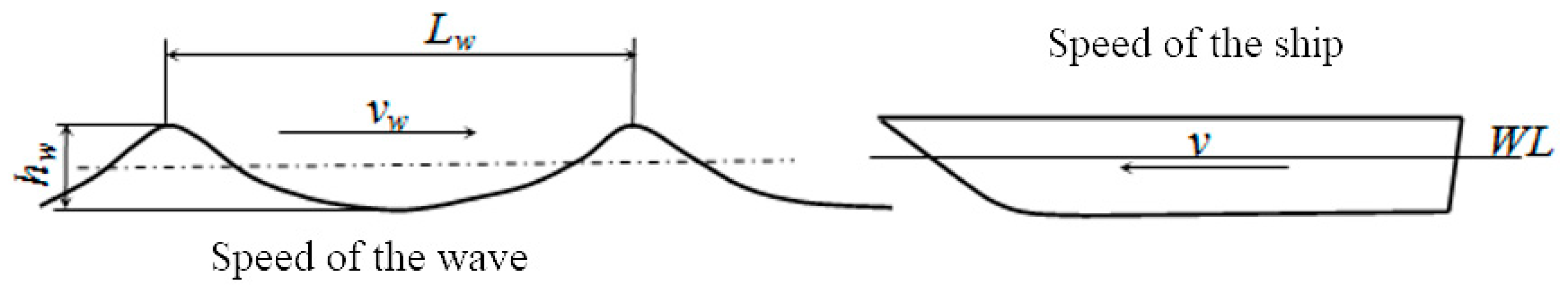
The equation relating the work of the forces acting on the ship when it encounters a wave (
Figure 1) will have the form.
Figure 1.
Scheme of the meeting of the vessel and the wave [
6].
Figure 1.
Scheme of the meeting of the vessel and the wave [
6].
where
Rw - the work of water resistance forces;
Tw- the work of the traction force;
Ew- the total energy of the wave.
Water resistance and traction forces have opposite directions. The work that these forces do have different signs and compensate each other until they meet the wave. Considering the fact that water resistance and traction force, when moving on a wave, will change their values, it can be assumed that these two forces, on average, will compensate each other. A change in the values of these forces will occur due to a change in the area of the wetted surface, pitching, the direction of action of the screw, and the exit of the screw from the water.
3. Analysis: The Total Energy of the Wave
There are the following hypotheses about regularities, which are used to describe the outline of the wave profile: sinusoidal regularity, trochoidal and cycloidal. Sea waves can best be described using trochoid waves [
7] (
Figure 2).
All further statements about wave energy are taken from [
7]. Wave energy consists of kinetic and potential energy. The layer of thickness
and length
were selected. The kinetic energy is
.
The radius of the orbit
of the liquid particle and the angular speed of rotation of the liquid particles
are represented in the equation
where
Lw is the wavelength;
γ- density of sea water.
The differential of a variable
can be represented as a differential of a radius
. This equation represents the equality of two ratios. The left side is the ratio of the layer thickness
to the wavelength. The right side is the ratio of the increment of the radius of the orbit of a liquid particle
to the length of the circumscribed circle. After substituting the value
in the equation Equation (4)
After integrating of the equation Equation (5) in the range from
is the surface of the liquid to
is the depth of damping of the oscillatory movements of the liquid, the equation in the form will be obtained
The value of the angular velocity of a particle of liquid is
. After substituting this value into Equation (6), the kinetic energy is
Taking into account that the height of the wave is equal to two of its radii
, the formula Equation (7) will be in the form
The specificity of trochoid wave is expressed in the fact that the axis of the trochoid, when the movement occurs, is higher than the axis of comparison by a value
(
Figure 2).
The potential energy of a layer, with thickness
is
One of the properties of the trochoid wave is the ratio of the areas of the profile
and
. The first area is less than the second by half the area of the producing circle with a radius of
.
So, the distance
is calculated as follows
After substituting Equation (11) into Equation (9) and integration of the resulting differential equation, in the range from
(the surface of the liquid) to
(the depth of damping of the oscillatory movements of the liquid), the equation in the form will be obtained
The total energy of a trochoid wave per unit width of the wave surface
After multiplying (13) by the acceleration of gravity and the width of the vessel, the total wave energy, in units of kNm, will be obtained.
4. Solution: Derivation of the Formula for Force Using the Criterion EWC
The basis of the criterion
is an inequality that connects the kinetic energy of the ship and the total energy of the wave, which affects the ship along its width, in case of oncoming sea waves.
The right-hand side of this inequality is obtained after transforming the mathematical expression for the total energy of the wave acting on the width of the vessel , .
When deriving the criterion, Buckingham’s similarity theorem was applied and the formula was obtained.
Any mathematical dependence can be presented in the form of criteria . Where is the number of variables, is the number of units. In our case, the number of variables is four (, , , ), units of measurement are three (kg, m, sec). Number of possible criteria - .
It is possible to use to determine the longitudinal accelerations that occur when the vessel encounters a wave. If we compare two criteria: and Newton’s criterion , it can be noted that the parts of these criteria and are related to the defining linear dimensions and , body mass and speed. Parts of the equations and are forces. The value of the wave force is affected by the height of the wave and the ratio of the wavelength to the height.
If the value of the force is calculated, then it is possible to determine the value of the acceleration acting on the body and compare it with the values of the accelerations obtained on the basis of observations on board a real ship. In the modern version of CSS Code, a ship with a length of 100 m and a speed of 15 knots is chosen to study the accelerations acting on the ship. Correction coefficients are used for vessels of other sizes. A similar approach is used in the International Convention on Load Lines. This Convention introduces the concept of a standard ship with certain characteristics [
8].
5. Results: Calculation of Longitudinal Accelerations
As mentioned above, the force with which the wave affects the vessel is calculated by the formula, Kn
This follows from comparisons of Newton’s criterion and the criterion of .
Mass displacement of the vessel
To calculate the value of the accelerations, information about the mass of the vessel is required. The mass tonnage of the vessel described in [1] can be calculated based on the ratio of the main dimensions of the vessel with normal qualities.
For ships of different types, there are ratios of main dimensions that provide the ship with sufficient seaworthy qualities. In modern literature, a lot of attention is paid to the selection of vessel characteristics [
9]. To ensure the propulsion of a slow-speed vessel, a ratio of the length of the vessel to the width equal to six is required. This ratio is characteristic of a well-streamlined body, from the point of view of hydrodynamics. The ratio of the ship’s width to the draft is usually in the range of two to four, which provides the ship with sufficient stability. The block coefficient for slow-speed vessels takes an average value of 0.8. If we take into account all the above considerations, then the mass of a standard vessel with a length of 100 m, which is mentioned in the regulatory document [
1], will be about 8343 tons.
The differential equation of the ship’s motion has the form
where
T - traction force;
R - water resistance;
F- the force of the wave affects the ship.
Water resistance and traction force have opposite signs and will change their values when moving on a waves. These two forces will, on average, offset each other.
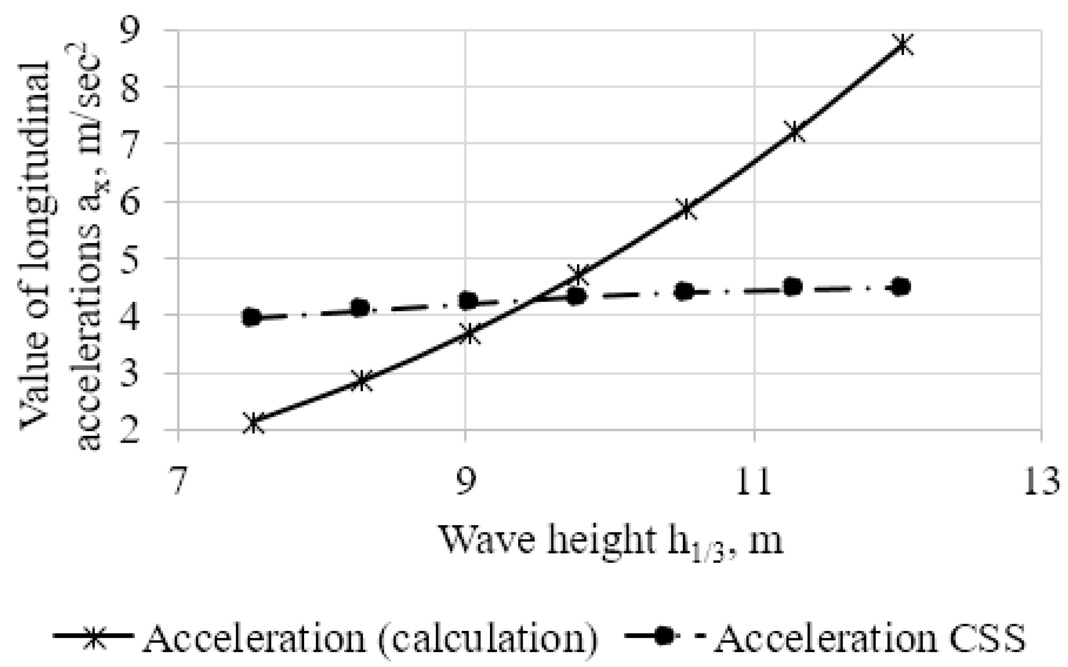
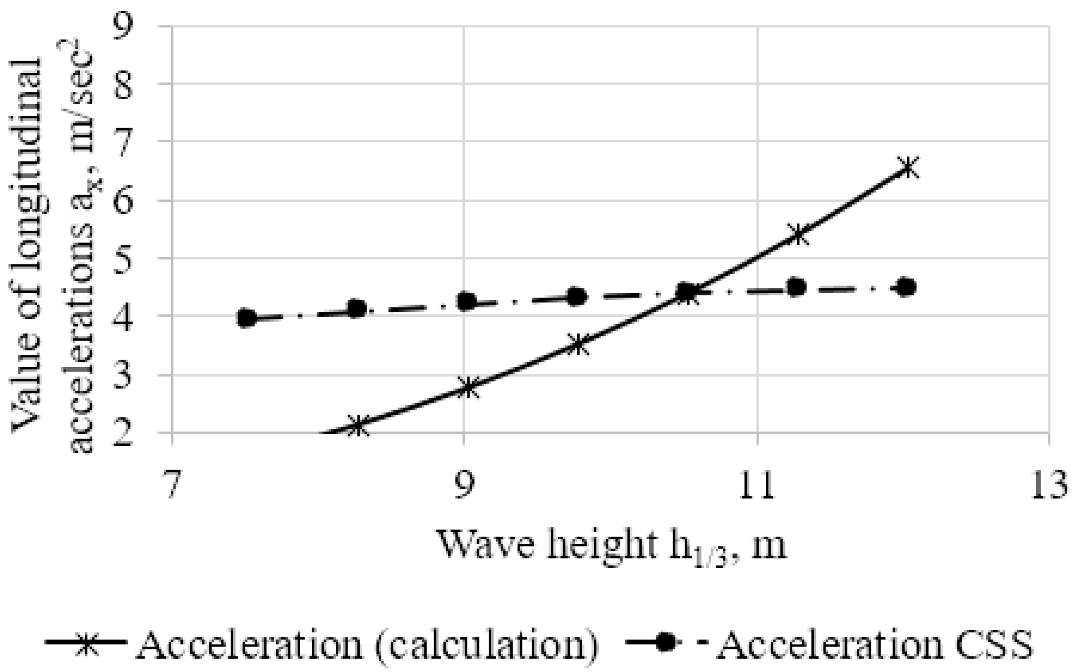
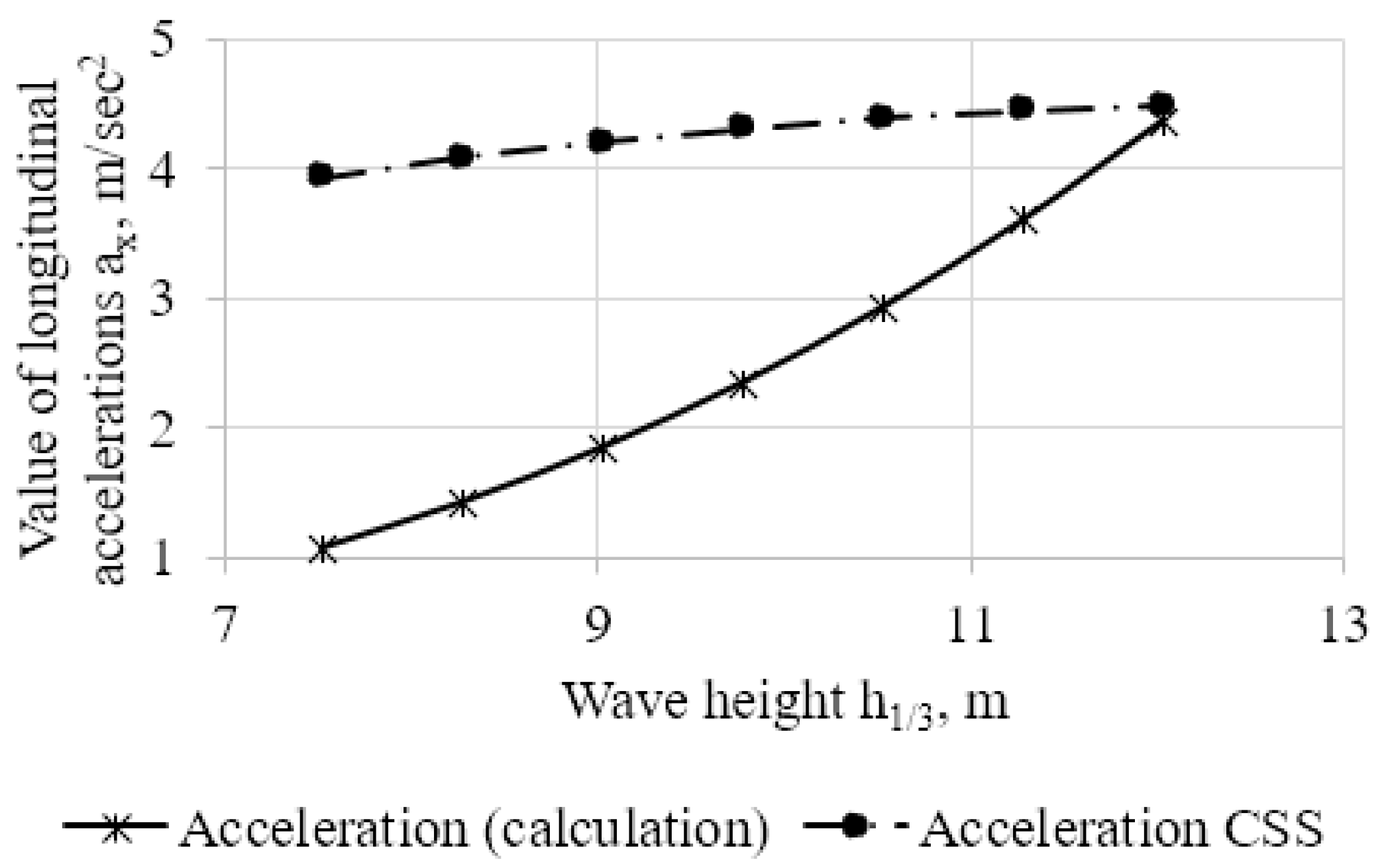
Calculation of longitudinal accelerations is possible from the formula
Figure 3,
Figure 4 and
Figure 5 show the results of calculations of accelerations, according to the proposed method and according to the Rules [
1], with different ratios of the wavelength to its height
.
In the Rules [
1], another simplified method of calculating the strength of securing devices for cargo is proposed. In this case, the values of the accelerations acting on the load in horizontal directions are assumed to be equal to the free fall acceleration. As can be seen from
Figure 3, when the wave height is close to 12 m, the value of the longitudinal acceleration approaches the value of the acceleration of free fall.
The ratio of the wavelength to its height significantly affects the value of accelerations, which must be taken into account during calculations. For a wave height of 12 m and =10, the calculated values of the accelerations and the recommendations of the Code of Safe Practice for Cargo Stowage and Securing (CSS Code) coincide.
The results obtained in this work are relevant, taking into account modern works devoted to adverse changes in the seaworthiness of a vessel that occur during cargo transportation under the influence of many random events [
10].
6. Conclusions
The new method for estimating the values of longitudinal accelerations proposed in this work helps to more accurately determine the forces acting on the ship’s hull, mechanisms, securing devices for cargo and crew. It becomes possible to clearly set the parameters of waves acting in different zones. This methodology makes it possible to implement a differential approach to each specific case related to the operation of the vessel in different navigation areas. Which, in turn, leads to an effective assessment of the crew’s working conditions and an effective choice of securing devices for cargo.
Nomenclature
|
- Froude number based on volume; |
|
- displacement volume; |
|
- residuary resistance displacement ratio; |
|
- relative length; |
|
- relative width; |
|
- block coefficient; |
|
- prismatic coefficient; |
|
- Froude number based on length; |
|
- length displacement ratio; |
|
- frictional resistance coefficient; |
| ρ |
- density of water; |
|
- wetted surface area; |
|
- frictional resistance; |
|
- total resistance. |
|
- the work of the traction force; |
|
- the total energy of the wave. |
References
- International Maritime Organization (IMO). Code of Safe Practice for Cargo Stowage and Securing (CSS Code). 2023. https://marineregulations.dandocs.com.
- Maritime Safety Committee. Resolution MSC.5(48). Adoption of the International Code for the Construction and Equipment of Ships Carrying Liquefied Gases in Bulk. 1983. https://marineregulations.dandocs.com.
- Hossein Ghaemi, Hamid Zeraatgar, Mojtaba Barjasteh. Investigating Fuel Injection Strategies to Enhance Ship Energy Efficiency in Wave Conditions. Polish Maritime Research. 2024. [CrossRef]
- F. Peґrez Arribas. Some Methods to Obtain the Added Resistance of a Ship Advancing in Waves. 2006. [CrossRef]
- Daniel Veen, Tim Gourlay. A Combined Strip Theory and Smoothed Particle Hydrodynamics approach for Estimating Slamming Loads on a Ship in Head Seas. Ocean Engineering. 2012. [CrossRef]
- Oleksandr Kanifolskyi, Larysa Krysiuk. New Area of Application of the Energy Wave Criterion (EWC): Determination of the Coastal Navigation Voyage. Journal of Marine Science and Technology. 2022. [CrossRef]
- Alferev, M. Hydromechanics. River transport; 1961.
- International Maritime Organization. International Convention on Load Lines. 1966.
- Shumylo, O., Yarovenko, V., Malaksiano, M., Melnyk, O. Comprehensive Assessment of Hull Geometry Influence of a Modernized Ship on Maneuvering Performance and Propulsion System Parameters. Pomorstvo. 2023. [CrossRef]
- Melnyk, O., Onyshchenko, S., Onishchenko, O., Shcherbina, O., & Vasalatii, N. (2023). Simulation-based method for predicting changes in the ship’s seaworthy condition under impact of various factors. In Studies in Systems, Decision and Control (Vol. 481, pp. 653–664). Springer. [CrossRef]
|
Disclaimer/Publisher’s Note: The statements, opinions and data contained in all publications are solely those of the individual author(s) and contributor(s) and not of MDPI and/or the editor(s). MDPI and/or the editor(s) disclaim responsibility for any injury to people or property resulting from any ideas, methods, instructions or products referred to in the content. |
© 2025 by the authors. Licensee MDPI, Basel, Switzerland. This article is an open access article distributed under the terms and conditions of the Creative Commons Attribution (CC BY) license (http://creativecommons.org/licenses/by/4.0/).