
Submitted:
17 January 2025
Posted:
17 January 2025
You are already at the latest version
Abstract
This study investigates the dynamic behaviors of hypoid gear rotor systems under variable tidal current energy harvesting conditions through numerical simulations and experimental validation. The research examines dynamic responses induced by cyclical tidal current variations, which generate fluctuating loads and bidirectional rotational speeds in tidal energy conversion systems. Two hypoid gear pairs, modified through precise manufacturing parameters, are evaluated to optimize tooth contact patterns for bidirectional tidal loading conditions. The analysis employs coupled torsional equations incorporating variable transmission error and mesh stiffness, validated through experimental testing using a purpose-built apparatus measuring both torsional and translational vibrations across diverse tidal velocity profiles. Results demonstrate that second-order primary resonances exhibit heightened vibration intensity during flow reversal phases, with implications for power efficiency and acoustic emissions. The findings advance the understanding of hypoid gear optimization for tidal energy harvesting systems, particularly regarding tooth contact patterns' influence on dynamic stability under bidirectional flows.
Keywords:
Hypoid gears
; Dynamic behaviors
; Transmission error
; Mesh stiffness
; Tidal current energy
1. Introduction
Hypoid gears serve as critical power transmission components in tidal current energy converters (TCECs), where they facilitate the conversion of bidirectional tidal flows into rotational mechanical energy [1]. In tidal energy applications, these gears encounter distinct challenges due to the cyclical nature of tidal current loading and the periodic flow reversals characteristic of tidal environments [2]. While conventional performance metrics such as transmission error (TE), tooth root strength, and surface wear remain crucial considerations, the dynamic behavior of hypoid gears under variable tidal current conditions introduces additional complexities due to bidirectional loading patterns. The time-varying TE and mesh stiffness (MS) function as primary internal excitation sources, whose characteristics are significantly influenced by the predictable yet varying loads and reversing operational speeds inherent in TCECs [3]. Variations in TE and MS parameters, amplified by tidal current fluctuations and flow reversals, can induce complex dynamic behaviors in the rotor system’s speed and load responses across different tidal cycles. These dynamic characteristics are further complicated by variations in tooth contact conditions, which emerge from microscale deviations in tooth form geometry and become particularly critical during tidal flow transitions and reversal periods [4]. Within tidal energy applications, multiple tooth contact patterns may manifest across different hypoid gear pairs of identical design specifications, attributable to manufacturing tolerances and machining parameter variations, which become especially significant under bidirectional loading. Of particular importance in TCECs is the prevention of edge tooth contact during flow reversals, necessitating comprehensive inspection protocols for hypoid gears prior to deployment in tidal environments, as such contact patterns could induce severe vibrations in the rotor system under cyclical tidal loading conditions.
Researchers assumed that the time-varying TE and MS are the prominent exciting sources for the gearing systems. Many researchers specialized their studies on TE and MS to evaluate dynamic performances of their interest through static performances of the gearing system. Hypoid gears have much more complex tooth surface, typically quasi-conjugated, than that of involute spur gears. Extensive research work in the past decades found it difficult to carry out the loaded tooth contact analysis (LTCA) of hypoid gears by the pure analytical approach to obtain exact solutions for load distribution, tooth contact deformation, and tooth bending and shear, as well as the final results TE and MS by certain formulas based on intermediate results. In all cases, the FE-based semi-analytical LTCA approach is significantly developed, and it is powerful enough to give the desired results in the past decade, benefiting from the computational efficiency. Wang et al. [5] proposed a methodology to avoid trial and error in obtaining a satisfied design of hypoid gears, and the FE-based semi-analytic LTCA is applied in their work to calculate the bending stress of the tooth root. Liu et al. [6] investigated the impact of work-holding equipment errors on the contact characteristics of face-hobbed hypoid gears, and a mathematical model considering both radial and angular eccentric errors. Liang et al. [7] investigated the effects on the tooth contact characteristics for the face-hobbed hypoid gears under different blade sections, and the contact pattern is compared between the linear, circular, and polynomial blades based on the FE tooth contact model. Li et al. [8,9,10] introduced a novel digital modeling technique for the real tooth surfaces of a hypoid gear pair, utilizing a non-geometric feature segmentation and interpolation approach. Cooley [11] proposed two determining approaches for spur gears mesh stiffness, average slope, and local slope using on the FE method, and a local slope difference formula for dynamic studies. In addition to the FE model, other researchers searched for numerical solutions to LTE of hypoid gears. Huang et al. [12,13] used the conjugate approach to frictional loss and surface wear studies of hypoid gears. Ding et al. [14] proposed a topography correction method for the tooth surface of hypoid gears, and the machining settings are identified from the proposed nonlinear least square algorithm. Li et al. [15] introduced the wedge-shaped contact form into the calculation of contact stiffness and proposed a gear time-varying MS calculation method that takes into account the tooth surface processing characteristics. Liu et al. [6] employed quasi-static LTCA to investigate the contact characteristics and gear geometry with radial and angular eccentric errors. A method for decomposing the total TE into long-wave and short-wave components is proposed, and a correspondence between these components and gear blank and flank geometry is established.
Concerning dynamic studies of hypoid gears, researchers established many dynamic models and explored the influence of various factors on dynamic performances. Shi et al. [16] presented a dynamic model for hypoid gears, considering the influences of dynamic MS caused by the dynamic mesh force. Song et al. [17] analyzed the effects of bearing rollers of different sizes on the dynamics of the shaft bearing system of hypoid gears, considering factors such as the magnitude, number and position distribution of the error. Wang et al. [18] proposed a general non-linear time-varying torsional model of hypoid gears to investigate dynamic behaviors, and typical behaviors reported in spur gears were observed, jump discontinuities, subharmonic and chaotic states from the computational results. Karagiannis et al. [19] proposed an alternative formulation for dynamic transmission error (DTE) of hypoid gears, and revealed some important dynamic behaviors never previously reported. Mohammadpour et al. [20] conducted pioneering work to investigate the coupling between dynamics and tribology for differential hypoid gears of vehicles. Athanasopoulos et al. [21] presented a new method to calculate the sliding and rolling speeds along the full path of contact on the tooth surface of hypoid gears. Song et al. [22] proposed a hybrid dynamic model to investigate hypoid gears coupled with off-sized bearing rollers. Shi et al. [16] presented a dynamic model for hypoid gears considering the influence of dynamic MS, which is influenced by the dynamic force of the mesh. It demonstrated that incorporating dynamic MS leads to more accurate predictions of gear dynamic responses, particularly at resonance peaks and under light load conditions. Huangfu et al. [23] investigated the effects of tooth modifications on the dynamic characteristics of thin-rimmed gears under surface wear, to optimize load distribution and reduce vibration throughout the wear process. Zheng et al. [24] presented an analytical approach to modeling the MS of high-speed spur gears, considering the centrifugal effect and its influence on gear deformation and load sharing.
This study investigates the dynamic behavior variations between two hypoid gear configurations under distinct tooth contact conditions specifically designed for tidal current energy harvesting applications. The baseline hypoid gear design, adapted from a commercial vehicle transmission system, is modified to accommodate bidirectional tidal flows, with two gear pairs manufactured under different milling parameters to establish contrasting tooth contact patterns: one exhibiting optimal contact characteristics for tidal applications, and the other presenting marginal edge contact to evaluate system sensitivity. A comprehensive nonlinear dynamic torsional model is developed, incorporating the time-varying TE and MS parameters derived from FE-based tooth contact analysis, specifically accounting for bidirectional loading conditions characteristic of tidal current variations. The dynamic responses under variable tidal loading conditions are numerically solved using the Runge-Kutta method, with particular attention to behavior during flow reversal phases. Experimental validation is conducted using a purpose-built tidal current simulation test rig, employing high-precision rotary encoders for torsional vibration measurements of both pinion and gear, complemented by triaxial acceleration measurements to capture the complete dynamic response under simulated tidal flow conditions. The numerical and experimental results are systematically analyzed to evaluate the influence of tooth contact patterns on system performance under variable tidal current conditions, leading to significant insights for optimizing hypoid gear designs in tidal energy harvesting applications.
2. Power Conversion Modeling of Drivetrains in Tidal Current Energy Converters
The enhancement of TCEC power generation capabilities necessitates optimized design of power conversion systems that enable energy capture at reduced cut-in velocities, facilitating the conversion of fluctuating low-speed turbine rotations to stable high-rated outputs. Performance validation of the drivetrain system under varying tidal velocities was accomplished through experimental studies using a TCEC configuration incorporating both hydro-turbine and drivetrain components in controlled flume conditions. Figure 1 illustrates the experimental TCEC configuration in this study. The extractable hydrokinetic power from tidal currents via a hydro-turbine can be expressed as
where is the turbine swept area, is that seawater density, is the power coefficient, and is the tidal current velocity.
The relationship in Equation (1) quantifies the extractable energy for a specified hydro-turbine’s swept area operating at a defined power coefficient within a tidal stream. The hydro-turbine’s power coefficient primarily correlates with its tip-speed-rario (TSR), which is
where is the design-dependent torque coefficient and is the TSR, which is
with is the rotor radius and is hydro-turbine’s angular velocity. For this study, the hydro-turbine’s torque coefficient is [25]
where
with is the pitch angle, i.e., 15° in this study. Using the TSR relationship in Equation (3), the hydro-turbine’s angular velocity is
The TCEC operational torque, crucial for drivetrain load distribution analysis, can be expressed as
This operational torque serves as the primary input parameter for the drivetrain system. The drivetrain facilitates energy transfer from the generated power to the generator assembly. Maintaining optimal performance across variable tidal velocities requires consistent TSR regulation at its designed optimal value.
The hypoid gear dynamic torsional model under variable tidal current energy harvesting conditions is shown in Figure 2, and its torsional equations include Equations (8) and (9) in this study, which serves to solve torsional vibrations of the pinion and gear, respectively. This study confines attention to the dynamic behavior under two different tooth contact conditions subject to different milling settings [26]. Thus, TE and MS of two pairs of gears obtained from the respective milling settings are used as parametric input conditions to the torsional equations. The translational vibrations of the bearing systems of the rotor system are ignored from the dynamic model; instead, they are mainly investigated by large numbers of experimental tests from data measured by a 3-axis accelerometer.
The torsional equations to solve the torsional vibrations of the pinion and gear are written as
where , , , and are the torsional vibrations of the pinion and gear in angles, and radii of contact point to the pinion and the gear axes, respectively, and are the moment of inertia of the pinion and the gear, respectively, is the gear ratio, , , and are meshing damping, MS, and TE of the hypoid gear rotor system, respectively. Meshing damping which reflects the effects of viscous and friction is assumed to be constant in this torsional model. The time-varying MS is an unknown function that can be expressed in concept as , which means its value is affected by the combination of angular deviations from the theoretic conjugate position of the contact point on the pinion and the gear tooth surfaces, and the static TE over meshing cycles for time.
3. FE Tooth Contact Model Under Variable Tidal Current Conditions
This investigation analyzes the dynamic behavior characteristics of hypoid gear rotor systems under variable tidal current conditions, focusing on the comparative assessment of different tooth contact patterns generated through specialized milling parameters. TE and MS variations for two distinct gear pair configurations are computed using a high-fidelity FE tooth contact model, which incorporates bidirectional loading profiles characteristic of tidal current fluctuations. The accuracy of the three-dimensional hypoid gear model, particularly critical for precise computation of TE and MS under reversing tidal flows, is established through an advanced geometric construction methodology that accounts for time-varying contact conditions. This methodology enables detailed analysis of tooth contact behavior during critical tidal flow transition periods, where loading direction changes significantly impact gear mesh characteristics.
3.1. Tooth Contact Model
This section presents the modeling method of 3D hypoid gears and the FE analysis of the 3D model for the approach in detail to TE and MS. CATIA is well known for the ability of model work to construct complex surfaces, so software is applied in this study to construct the 3D model of hypoid gears. In the simulation of this study, special machines Gleason 116 and 609 are chosen to generate the tooth surface of the specified pair of hypoid gears in CATIA. The face-milled process is applied to machine the pinion and the gear. Basic Visual programming codes drive the milling process through the Macro interface of CATIA, which simulates Gleason 116 generating the pinion and Gleason 609 forming the gear. Figure 3 shows the grinding settings of the Gleason 116 machine tool in Figure 3b and 609 in Figure 3c, respectively, and Figure 3a the grinding process of the pinion and the gear that illustrates the relative positions of the 3D cutter head and the workpiece. The pinion generating settings include ten: four workpiece settings, axial position , horizontal position , vertical position and root angle ; four cutter head settings, S, q, i, and j; and the rolling angle of the workpiece , and the cradle angle , where is the rolling ratio. Gear formation settings include six: four workpiece positioning settings, that is, , , , and ; and two cutter head positioning settings, that is, H and V.
Figure 3a shows that Boolean operations remove the cutter head solid from the intersection with the workpiece solid at each predetermined workpiece angular position according to the rolling ratio in CATIA’s Part Design module. The tooth groove thereby is composed of a number of strip surfaces that should be stitched together. In CATIA’s Generative Shape Design module, strip surfaces are extracted and joined together, and uniformly distanced partition planes that are vertical to the pinion shaft axis are created. The intersection curves where the generated tooth groove intersects with the partition planes are extracted, and they are replaced after by spline curves in CATIA’s multi-sectional surface module. An integrated tooth surface thereby is constructed from these spline curve sections in CATIA’s Generative Shape Design module. A cover is added to the integrated tooth surface and is sealed together, and in the Part Design module the sealed tooth surface again becomes a solid tooth through the close-surface operation. Following some other solid editing work, the 3D pair of solid hypoid gears are finally worked out as shown in Figure 4a.
Figure 4b shows a piece of the FE model split from the complete hypoid gears in the HYPERMESH software. This study only requires a six-tooth pinion and gear for analysis, which significantly saves computing time and provides sufficient accuracy. The incompatible mode of element C3D8I is configured in HYPERMESH to perform grid division of the FE model, which is good at a high resolution of contact stress. Details of the six-tooth FE model of hypoid gears include that: the pair has a total of 308,988 elements with 350,998 nodes, mesh density is 25 × 62 nodes for the master tooth surface (drive side of the pinion), and 32 × 72 nodes for slave tooth surface (driven side of the gear). The element density of the surface of the slave tooth is predefined higher than the surface of the master tooth at 149% to avoid any penetration into each other. However, the same density would give more accurate results. Physical parameters include material characteristics: Young’s modulus and Poisson’s ratio predetermined as E = 2.1×10⁸ N/mm2, and v = 0.3 here. In this study, the work of computing TE and MS is executed in ABAQUS, due to the software’s strong capability of nonlinearity calculation for large deformations. To promote convergence, a small approach angle of 0.001 is set as an initial angle, which is an effective measure to ensure that the pinion and gear teeth are in slight contact.
3.2. LE and MS
TE of gears, including the unloaded and loaded, is commonly defined as the angular difference of the actual angular position of the driven gear from its mathematical conjugate angular position, therefore TE is conceptually expressed as , where , , , denote the tooth number and the actual angular positions of the pinion and gear, respectively. TE of hypoid gears is caused by multiple factors such as the geometric tooth form deviation, the assembly error under unloaded conditions, and under loaded conditions TE also involves surface compression, bending and shear, and torsion of the pinion and the gear and its shaft systems. For hypoid gears, the geometric tooth form deviation relates to its generating method, and the theoretic conjugate point only exists at the reference point on the center of the pinion and the gear tooth surfaces, which is the biggest difference from the involute gears. Missing the mathematic reference tooth surface makes it extremely difficult to obtain an accurate TE of hypoid gears by either the analytic or the numeric method; in contrast, involute gears have a reference datum involute surface. The FE method that relies on computing power is increasingly becoming an effective tool to produce a relatively accurate TE with the development of computing technology. However, TE by the FE method is still dependent on the accuracy of the tooth contact model to simulate the generating process of actual milling machines. Detailed construction process of 3D and FE models of hypoid gears which serve to compute TE and MS of this section are presented in Section 3.1.
In addition to TE, the FE method is also wildly involved in the MS calculation of involute gears. Cooley [11] proposed two determining approaches of the average slope and the local slope to calculate the MS of the spur gears using the FE method. In Cooley’s two approaches, the FE tooth contact model of spur gears is utilized for obtaining tooth contact compression, tooth bending and shear for a span of specified torque loads. Cooley made careful comparisons between two approaches and came up with suggestions that the average slope more resembles a static analysis and that the local slope can work well on dynamics. The average slope mathematically is an arithmetic formula, and the local slope is a finite-difference formula. This study suggests that the finite difference formula of the local slope is applicable for hypoid gears too, since the time-varying MS definition between spur gears and hypoid gears is nothing different, physically and mathematically. In this study, the local slope approach is applied to calculate the time-varying MS for hypoid gears supported by the data from the FE tooth contact model.
Stiffness refers to the ability of a material or structure to resist elastic deformation subject to force. The composite elastic deformation of a geared system should include many components, such as Hertz tooth contact compression, tooth bending and shear, and shaft system torsions, etc. Thereby, the composite static mesh stiffness of a geared rotor system at an instant time can be expressed as
where is the composite mesh stiffness, , , are the separated stiffness caused by the tooth contact compression, tooth bending and shear, respectively. is the local stiffness of the mesh caused by shaft torsions as it transmits the torque. In most cases, the hyoid gears have multiple teeth in contact simultaneously. Chang [27] thought that mesh stiffness of multi tooth contact is something like a set of parallel contact springs, and suggested that global composite stiffness of gears is expressed by summing up all discrete contact points to cover all major contact lines, giving
where N is the amount total of discrete segments, and km is the mesh stiffness of the mth tooth pair in contact. Cooley’s finite difference stiffness formula of the local slope approach for the mth single tooth pair in contact is represented as
where is tooth contact force, is composite mesh deflection of single tooth contact corresponds to the total approaching distance of a tooth contact segment caused by tooth contact compression, tooth bending and shear, and is a specified small increment of mesh deflection, i.e., finite difference term. Cooley also suggested the convenient way to give the mesh compliance form of Equation (13) as
It is much more convenient to give a desired incremental size of , and correspondingly it yields . It should be noted that excellent convergence is reported by setting the increment size at 1% of the nominal torque load [11]. This approach may cover all interesting torque ranges and avoid possible multiple stiffness curves due to nonlinearity of contact deformation.
4. Test Rig and Data Process
4.1. Experimental Setup
In this study, the torsional and translational vibrations of the hypoid gears are compared in certain forms between simulations and experiments for the rotor system. The test rig shown in Figure 5 has two optical rotary encoders on both shafts of the pinion and the gear sides of the hypoid gears, which can simultaneously measure the angular positions of the input and output. LTE is produced using measured data on the angular positions on the pinion and gear sides according to its definition formula in Section 3.2. LTE is obtained when the rotor system runs under quasi-static conditions for a certain number of angles at very low speed. Translational vibrations in three directions, x, y and z, are measured by a 3D accelerometer sensor placed on the upper surface of the hypoid gearbox. According to the figure, the physical units include (1) magnetic brake, (2) hypoid gear pair, (3) rotary encoders, (4) speed, torque sensors, (5) motor indexed by red dots, and (6) PCB Piezotronics 3-axes accelerometer.
The measurable finest angle of the optical rotary encoders on the input side is 2/217 rad, and the output side is 2/221 rad. Such resolution ratios on both sides can ensure the desired precision for the research objective of this study. The details of the acceleration meter are as follows: Brand PCB Piezotronics 3 axis accelerometer to measure translational vibrations in the x, y, and z directions, type 356B18, and National Instruments NI-9234 data acquisition board that connects to the sensor to collect vibration data in three directions. Key performances are: sensitivity ± 10% of 102 mV/(m/s2); measurable frequency range 0.5-3000 Hz with ± 5% sensitivity and bandwidth 110,000 Hz. Data of x, y, and z vibrations are processed by ORIGIN for the analysis of frequency components and by MATLAB for comprehensive analysis and reprocessing. The mesh frequency is calculated by = n rpm × / 60 s, where n rpm is the speed of input on the pinion side, and the sampling frequency must meet according to the sampling theory.
4.2. Data Process
The data collected from experimental tests are not suitable for direct comparison with simulations, which means that the data have to be processed in a certain form before being compared to the simulations. It is extremely difficult to capture the transient state to compare simulations and experiments under dynamic conditions of the rotor system of hypoid gears at a certain instant time of interest in practice. However, it is more practical to compare the load response and the speed response in the steady state, which reflects typical dynamic behaviors of hypoid gears, but can also be easily compared between simulations and experiments. In this study, the comparison is conducted mainly in the frequency domain and in the form of average maximum magnitude (AMM) and root mean square (RMS) in steady state after a specified period of time. The time domain data of vibrations picked from simulations and experiments are processed into the form of AMM and RMS before they are compared to each other. The load and speed responses, which are often used as two key performs to evaluate a dynamic system here in this study, are used to investigate the hypoid gears rotor system dynamic behaviors between different tooth contact conditions of the normal and edge and between the simulations and experiments. Detailed comparisons are performed next in Section 5 for hypoid gears of a domestic popular vehicle, the design data and generating settings are listed in Table 1.
For torsional vibrations, the angular positions in the unit of rad of the pinion and the gear are measured by two rotary encoders on both shafts. For easy comparison, the respective torsional vibrations of the pinion and the gear are combined as DTE in this study, when the rotor system of the hypoid gears runs at high speed and the dynamic effect must be considered. Let denote the n number of dynamic LTEs collected from its theoretic formula in steady state for a specified period of time, where is the specified period of the measurement operation, is the error value for a predefined time interval by dividing , and k is one of the tests or measurement operations, i.e., different k corresponds to any of the load and speed differences of the numbers of test operations. For each test operation k under different load and speed conditions, denotes the AAM operation obtained from , and denotes the RMS operation obtained from .
For translational vibrations, let , and denote the collected vibration data in x, y and z three directions, respectively, where k is the kth test operation under different load and speed conditions . The collected time domain vibration data in an instant of time t of experiments is transformed into frequency domain vibration data in the Origin software by performing the fast Fourier transform (FFT). Let n, , , and denote the order number, the pinion speed in units of rpm, the revolution, and the mesh frequencies of the rotor system, respectively. Thus, the revolution frequency is , the mesh frequency is , and the frequency of the primary resonances at the n th order (n = 1, 2, 3, ⋯) is . The RMS operation that expresses the overall intensity of the vibration is obtained from the vibrational magnitudes of the frequency domain in x, y and z directions at frequencies of different orders n.
5. Results
A local manufacturer of spiral bevel gears provides basic model data and machining data of hypoid gears. The machines Gleason 116 and 609 are employed to machine the specified solid hypoid gears for experimental tests, and two gear pairs are produced using different generating settings to create two different tooth contact conditions. The basic data for the hypoid gears chosen are shown in Table 1.
The pinion speed is set to 4500 rpm to take into account the effect of characteristic tidal current variations and flow reversals. For this study, the hypoid gear model 41×11 is subject to two different machine tool settings to produce two pairs of gears under two different tooth contact conditions according to the machine tool settings in Table 2 and Table 3, respectively. In the test design of this study, one pair of the two gear pairs has a normal tooth contact condition, and the other has a very slight edge contact condition to generate a different LTE and MS. Two gear pairs are obtained in two different tooth contact conditions by modifying the cutter radius and the other machine-tool settings, the details of which are omitted here.
5.1. LTE and Its Harmonic Components
LTEs are obtained from the FE tooth contact model and the rotary encoders in the experiment test rig, respectively. Two pairs of solid gears of the hypoid gears model are produced by Gleason 116 and 609 milling machines, and two 3D tooth contact models for FE analysis are constructed in CATIA according to the generating methods presented in Section 3, based on the model data in Table 1 and two different settings of the machine tool in Table 2 and Table 3, respectively. Then, two 3D models are transformed into FE tooth contact models by completing the mesh division. The tooth contact analysis for two different FE models is performed in ABAQUS, and experimental tests for two solid gear pairs are conducted on the test rig of Figure 5. Figure 6 shows their respective contact pattern, LTE, and its harmonic components of the primary resonances in the frequency domain under two different tooth contact conditions of interest. LTE curves under normal tooth contact conditions are in regular sine shape yielded from the FE model and the experiment, and under edge tooth contact condition it is not. The fast Fourier transformation (FFT) is performed for the LTE data in the time domain of the simulation and experiment, and Figure 6 shows their respective harmonic components of the primary resonances from frequencies 1 to 8, where is the mesh frequency. The simulation result is similar to the experiment, which suggests that hypoid gears under edge tooth contact conditions have more harmonic components than under normal tooth contact conditions. Experimental results suggest that in the frequency domain, LTE has a lot of high-frequency harmonic components under both edge and normal tooth contact conditions. In addition, tooth contact patterns demonstrate high sensitivity to milling parameter variations under bidirectional tidal loading conditions, resulting in distinct TE and MS characteristics during flow reversals.
LTE as one of the primary exciting sources contributes to hypoid gears unique dynamic characteristics, and loaded TE is often used to predict possible dynamic behaviors of the rotor system. However, the exact dynamic behaviors of the hypoid gear rotor system have to be evaluated by torsional vibrations; in most cases, it is reflected by the dynamic TE in the form.
Primary resonances of the first five orders of Fourier series of LTE thus can be written as
where i and are harmonic order and mesh frequency, respectively, and are the fundamental and the ith order harmonic component of LTE, respectively, and is phase position.
5.2. MS and Its Harmonic Components
MS is extremely difficult to measure directly from rotary encoders in experimental tests according to the accessible public literature. In this study, MS under two different tooth contact conditions is obtained from the Cooley local slope approach using the finite difference formula presented in Section 3.2, based on the angular position data of the FE tooth contact model.
Figure 7 shows the MS of two pairs of gears of the chosen commercial hypoid gears model which are obtained from the finite difference formula of Cooley’s local slope approach under two different normal and edge tooth contact conditions in the simulations using data from the FE tooth contact analysis. The MS of the gears is usually shaped like the letter “n”, that is, there are steep rises and falls on two sides, suggesting that the contact shift occurs on different teeth. The Fourier series of MS yielded from FFT replaces time-domain MS as input nonlinear exciting source to perform dynamic analysis using the dynamic motion model presented in Section 2, which provides a direct correlation between the exciting and response frequencies for this study. The time-varying MS for primary five orders of Fourier series shown in Figure 8 thus can be written as
where j and are harmonic orders and mesh frequency, respectively, and are the fundamental and the jth order harmonic components, respectively, and is phase position of the jth harmonic component. In parametric theory, the time-varying MS of the gear pair may enhance the second-order harmonic vibration of its rotor system.
5.3. Torsional Vibrations
The torsional vibrations of the pinion and the gear are usually illustrated by DTE (, ) which graphically assesses the dynamic characteristics of the geared systems. Figure 9 compares two DTE in steady state under two different tooth contact conditions of normal and edge, and the results of two tooth contact conditions are obtained from the torsional equations. (8) and (9). The DTE figures suggest that the periodicity in the case of normal tooth contact is better than in the case of edge tooth contact, or the case of edge tooth contact, the rotor system may behave periodically for a sufficiently long period. Comparisons also suggest that the dynamic behavior of hypoid gears under the edge tooth contact condition has more complex harmonic components. In contrast, LTEs under two different tooth contact conditions in a quasistatic state have perfect periodicity due to the milling consistency in each tooth form geometric deviation shown in Figure 6.
It is difficult to compare DTE directly between simulations and experiments, which are yielded, respectively, from the torsional equations and data of rotary encoders as measured. In reality, torsional vibrations of experiments are resultant signals that may include various harmonic components such as shaft revolution and noise of bearing systems, in addition to mesh frequency and harmonic frequencies excited by TE and MS. In this study, the DTE of the experiments is filtered to eliminate the shaft revolution signal in low frequency and the noise signal of the bearing systems in high frequency before comparing with that of simulations. Comparisons of load and speed responses are performed between the filtered experimental data and the simulation data, which are evaluated by AMM and RMS under two different tooth contact conditions. The proposed comparisons of the load and speed responses in AMM and RMS in this study are expected to provide a comprehensive and accurate understanding of the dynamic characteristics of the gear systems.
In simulations, the torsional vibrations of the pinion and the gear are solved numerically using the Runge-Kutta method from the torsional equations, Equations (8) and (9), which adopts and to be used as equation parameters to investigate the load and speed responses to exciting sources of TE and MS. In experiments, torsional vibrations of the gear pair are measured by two rotary encoders under different experimental testing conditions: speed ranges from 50 to 1,400 rpm on the pinion side, giving a mesh frequency = 0.55 - 15.4 kHz; and the sampling frequency is set four times the mesh frequency in each sufficiently high test; and load ranges from 50 to 450 Nm.
AMM and RMS of the load and speed responses are computed according to the data process method presented in Section 4.2, and they are compared between simulations and experiments. Two gear pairs of the normal and the edge tooth contacts are tested under the aforementioned conditions in the previous paragraph, and the measurement procedure starts after the rotor system runs for a long period, which ensures the system has been in a steady state. The blue and red curves in Figure 10 are experimental data in units of 10-2 rad in the left ordinate and simulation data scaled by dimensionless coordinates in the right ordinate, respectively.
Figure 10a and Figure 10b are load responses (LRs) in AMM and RMS of simulations and experiments, which are observed roughly the same between two different tooth contact conditions of the edge denoted by the dotted line and the normal denoted by the solid line. The load responses in AMM and RMS decrease slightly during light load and then increase continuously, and experiments suggest that the rotor system of hypoid gears is in an unstable state in which behaviors sustained angular vibrations between 50 and 75 Nm of the light input load condition.
Figure 10c, Figure 10d, Figure 10e, and Figure 10f are the speed response (SR) in AMM and RMS to the pinion speed between simulations and experiments under two different tooth contact conditions of the normal and the edge. Primary resonance vibrations are observed from both simulations and experiments, which are put together in figures. According to Sect. Section 4.2, primary resonances at the nth order are . Experimental tests of the two pairs of hypoid gears suggest that primary resonances of first and second orders occur at = 858 kHz and = 1,716 kHz, which correspond to pinion speeds of 1,300 rpm and 2,800 rpm, respectively. Figure 10c, Figure 10d, Figure 10e, and Figure 10f show that simulations and experiments share similar dynamic behaviors in SRs evaluated by AMM and RMS. Importantly, SR figures show that the gear pair under the edge tooth contact condition has a larger magnitude of AMM and RMS during flow reversals according to experiments and simulations, and the edge tooth contact has more complex harmonic components, which confirms empirical predictions.
5.4. Translational Vibrations
Translational vibrations of two pairs of hypoid gears are also investigated in this study by experiments that use an accelerometer shown in Figure 5 to collect vibrational accelerations of the time domain in x, y, and z directions. The data in the time domain are transformed by FFT into the data in the frequency domain and then processed into , which reflects the overall intensity of the vibration. The overall intensity of vibrations is for further analysis of gear pairs, and the detailed data process is presented in Section 4.2. Figure 11 shows the vibrational accelerations collected of the time domain from one of multiple experimental tests under different load and speed conditions. The time domain vibrational accelerations suggest that in the up and down direction has a slightly smaller magnitude than in the horizontal directions and . Figure 12 shows the vibrations in the frequency domain to examine consistency in different directions x, y, and z under the condition that the pinion speed remains at 3,000 rpm. At the remaining speed, frequencies of the first three orders of primary resonances are 1,980 kHz, 3,960 kHz, and 5,940 kHz, respectively. The multiple experimental tests suggest that the magnitudes of primary resonances of the gear pairs of hypoid gears in different directions are different.
In this study, the overall intensity of vibration that goes with the increase of the pinion speed is obtained from the accelerations in the collected time domain at each increase in the pinion speed which corresponds to the n fourth order vibrational frequency . The overall intensity of vibration in the frequency domain is compared between two pairs of gears under two different tooth contact conditions by a large number of experimental tests, as shown in Figure 13. The proposed comparisons suggest that the gear pair in the case of edge tooth contact has higher vibrational intensity than in the case of normal tooth contact. The general increase in the intensity of the vibration is significantly correlated with the increase in the pinion speed of the order n = 2, which means that the second order of the pair of gears of the hypoid gears increases power losses in tidal energy conversion. According to the figures, two pairs of gears under different tooth contact conditions of normal in solid line and edge in dashed line share a similar trend in three all orders n = 1, 2, and 3. However, the overall vibration intensity in the case of the edge tooth contact increases higher than in the case of the normal tooth contact along with the rotation speed of order n = 2.
6. Conclusions
This study presents a comprehensive investigation of hypoid gear dynamic behaviors under variable tidal current energy harvesting conditions, with particular emphasis on the effects of tooth contact patterns during bidirectional loading cycles. The study focuses on dynamic responses induced by internal excitation sources - specifically TE and MS - under characteristic tidal current variations and flow reversals. Comparative analysis of torsional and translational vibrations between the two gear configurations, supported by both numerical simulations and experimental validation, yields the following significant findings:
(1) Tooth contact patterns demonstrate high sensitivity to milling parameter variations under bidirectional tidal loading conditions, resulting in distinct TE and MS characteristics during flow reversals.
(2) Frequency domain analysis reveals that marginal edge tooth contact significantly amplifies high-frequency harmonic components of TE and MS, particularly during tidal flow transition periods.
(3) Speed response measurements across multiple experimental trials confirm that edge contact-induced harmonic components generate additional angular vibrations in the high-frequency domain during flow reversals, validating the numerical predictions from the torsional model.
(4) Under variable tidal current conditions, tooth contact patterns significantly influence system dynamics, with second-order primary resonances exhibiting elevated vibration intensities during flow transitions, leading to increased power losses in tidal energy conversion.
Author Contributions
Conceptualization, methodology and writing-D.H., Y.L. and X.Z.; software and validation-D.H. and Y.L.; formal analysis,data curation-D.H.; investigation and resources-X.Z.; writing—review and editing, supervision, project administration and funding acquisition-G.L. All authors have read and agreed to the published version of the manuscript.
Funding
This research was funded by the National Science Foundation under Grant No. 2329791.
Data Availability Statement
Data are contained within the article.
Conflicts of Interest
The authors declare no conflicts of interest.
References
- Li, G.; Zhu, W. A Review on Up-to-Date Gearbox Technologies and Maintenance of Tidal Current Energy Converters. Energies 2022, 15, 9236. [Google Scholar] [CrossRef]
- Khare, V.; Khare, C.; Nema, S.; Baredar, P. Tidal Energy Systems: Design, Optimization and Control; Elsevier, 2018.
- Elasha, F.; Mba, D.; Togneri, M.; Masters, I.; Teixeira, J.A. A hybrid prognostic methodology for tidal turbine gearboxes. Renewable Energy 2017, 114, 1051–1061. [Google Scholar] [CrossRef]
- Li, G.; Zhu, W. Time-Delay Closed-Loop Control of an Infinitely Variable Transmission System for Tidal Current Energy Converters. Renewable Energy 2022, 189, 1120–1132. [Google Scholar] [CrossRef]
- Wang, Q.; Zhou, C.; Gui, L.; Fan, Z. Optimization of the loaded contact pattern of spiral bevel and hypoid gears based on a kriging model. Mechanism and Machine Theory 2018, 122, 432–449. [Google Scholar] [CrossRef]
- Liu, S.; Song, C.; Zhu, C.; Liang, C.; Yang, X. Investigation on the influence of work holding equipment errors on contact characteristics of face-hobbed hypoid gear. Mechanism and Machine Theory 2019, 138, 95–111. [Google Scholar] [CrossRef]
- Liang, Siyuan Yang, X. Investigation of the effects with linear, circular and polynomial blades on contact characteristics for face-hobbed hypoid gears. Mechanism and Machine Theory 2020, 146. [Google Scholar]
- Li, G.; Wang, Z.; Kubo, A. The modeling approach of digital real tooth surfaces of hypoid gears based on non-geometric-feature segmentation and interpolation algorithm. International Journal of Precision Engineering and Manufacturing 2016, 17, 281–292. [Google Scholar] [CrossRef]
- Li, G.; Wang, Z.; Kubo, A. Error-sensitivity analysis for hypoid gears using a real tooth surface contact model. Proceedings of the Institution of Mechanical Engineers, Part C: Journal of Mechanical Engineering Science 2017, 231, 507–521. [Google Scholar] [CrossRef]
- Li, G.; Zhu, W. An Active Ease-Off Topography Modification Approach for Hypoid Pinions Based on a Modified Error Sensitivity Analysis Method. ASME Journal of Mechanical Design 2019, 141, 093302. [Google Scholar] [CrossRef]
- Cooley, C.G.; Liu, C.; Dai, X.; Parker, R.G. Gear tooth mesh stiffness: A comparison of calculation approaches. Mechanism and machine theory 2016, 105, 540–553. [Google Scholar] [CrossRef]
- Huang, D.; Wang, Z.; Li, G.; Zhu, W. Conjugate approach for hypoid gears frictional loss comparison between different roughness patterns under mixed elastohydrodynamic lubrication regime. Tribology International 2019, 140, 105884. [Google Scholar] [CrossRef]
- Huang, D.; Wang, Z.; Kubo, A. Hypoid gear integrated wear model and experimental verification design and test. International Journal of Mechanical Sciences 2020, 166, 105228. [Google Scholar] [CrossRef]
- Ding, H.; Wan, G.; Zhou, Y.; Tang, J.; Zhou, Z. Nonlinearity analysis based algorithm for identifying machine settings in the tooth flank topography correction for hypoid gears. Mechanism and Machine Theory 2017, 113, 1–21. [Google Scholar] [CrossRef]
- Li, Y.; Li, G.; Wang, Z.; Mayfield, W. On gear time-varying meshing stiffness calculation considering indexing feeds and processing characteristics of gear shaping processing. Precision Engineering 2024, 91, 418–432. [Google Scholar] [CrossRef]
- Shi, Z.; Li, S. Nonlinear dynamics of hypoid gear with coupled dynamic mesh stiffness. Mechanism and Machine Theory 2022, 168, 104589. [Google Scholar] [CrossRef]
- Song, C.; Bai, H.; Zhu, C.; Wang, Y.; Feng, Z.; Wang, Y. Computational investigation of off-sized bearing rollers on dynamics for hypoid gear-shaft-bearing coupled system. Mechanism and Machine Theory 2021, 156, 104177. [Google Scholar] [CrossRef]
- Wang, J.; Lim, T.C.; Li, M. Dynamics of a hypoid gear pair considering the effects of time-varying mesh parameters and backlash nonlinearity. Journal of Sound and Vibration 2007, 308, 302–329. [Google Scholar] [CrossRef]
- Karagiannis, I.; Theodossiades, S. An alternative formulation of the dynamic transmission error to study the oscillations of automotive hypoid gears. ASME Journal of Vibration and Acoustics 2014, 136, 011001. [Google Scholar] [CrossRef]
- Mohammadpour, M.; Theodossiades, S.; Rahnejat, H. Multiphysics Investigations on the Dynamics of Differential Hypoid Gears. ASME Journal of Vibration and Acoustics 2014, 136, 041007. [Google Scholar] [CrossRef]
- Athanasopoulos, E.; Salpistis, C.; Mohammadpour, M.; Mihailidis, A.; Theodossiades, S.; Grekoussis, R. Calculation of the kinematics of hypoid gears towards developing a method for an equivalent crossed helical gear pair selection for use in tribological experimental evaluations. Proceedings of the Institution of Mechanical Engineers Part K Journal of Multi-body Dynamics 2017, 231, 519–537. [Google Scholar] [CrossRef]
- Song, C.; Bai, H.; Zhu, C.; Wang, Y.; Wang, Y. Computational investigation of off-sized bearing rollers on dynamics for hypoid gear-shaft-bearing coupled system. Mechanism and Machine Theory 2021, 156, 104177. [Google Scholar] [CrossRef]
- Huangfu, Y.; Zhao, Z.; Ma, H.; Han, H.; Chen, K. Effects of tooth modifications on the dynamic characteristics of thin-rimmed gears under surface wear. Mechanism and Machine Theory 2020, 150, 103870. [Google Scholar] [CrossRef]
- Zheng, X.; Luo, W.; Hu, Y.; He, Z.; Wang, S. Analytical approach to mesh stiffness modeling of high-speed spur gears. International Journal of Mechanical Sciences 2022, 224, 107318. [Google Scholar] [CrossRef]
- Li, G.; Zhu, W. Control and Flume Flow Experiments of a Tidal Current Energy Converter with an Infinitely Variable Transmission. IEEE/ASME Trans. on Mechatronics 2024, 29, 2803–2811. [Google Scholar] [CrossRef]
- Liu, Y.; Chen, L.; Li, G. Multi-Points Control for Face-Milled Spiral Bevel Gears with A Predesigned Fourth-Order Motion Curve. Machines 2024, 12, 34. [Google Scholar] [CrossRef]
- Chang, L.; Liu, G.; Wu, L. A robust model for determining the mesh stiffness of cylindrical gears. Mechanism and Machine Theory 2015, 87, 93–114. [Google Scholar] [CrossRef]
Figure 1.
Layout structure of the TCEC including the hydro-turbine, a hypoid gear pair, and the gearbox.
Figure 1.
Layout structure of the TCEC including the hydro-turbine, a hypoid gear pair, and the gearbox.
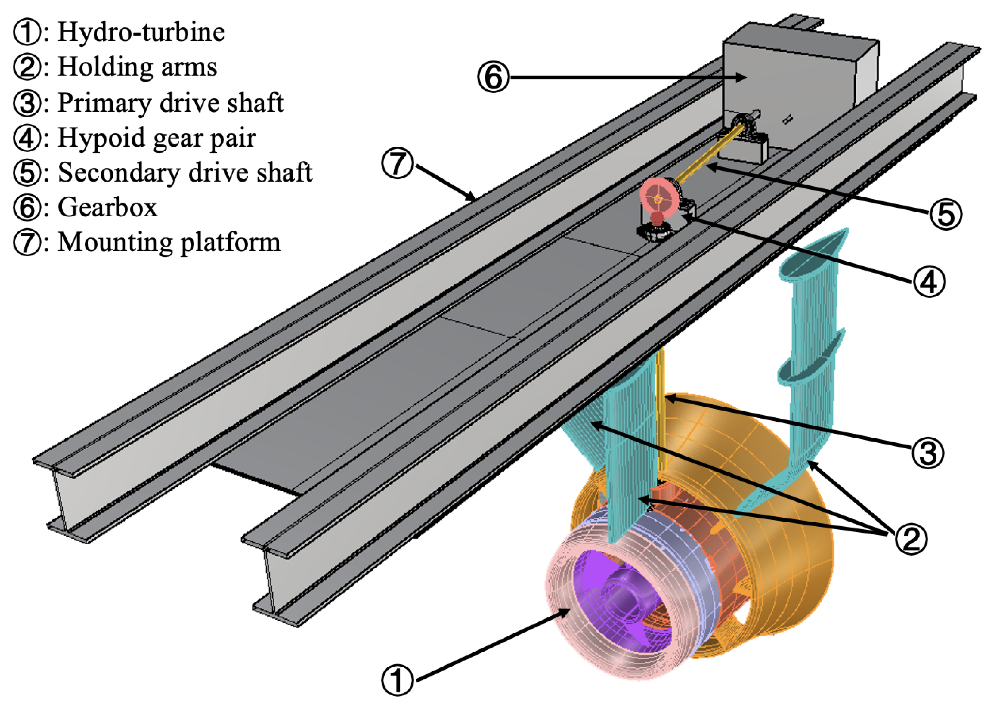
Figure 2.
A dynamic model of a hypoid gear system to reflect its angular vibrations.
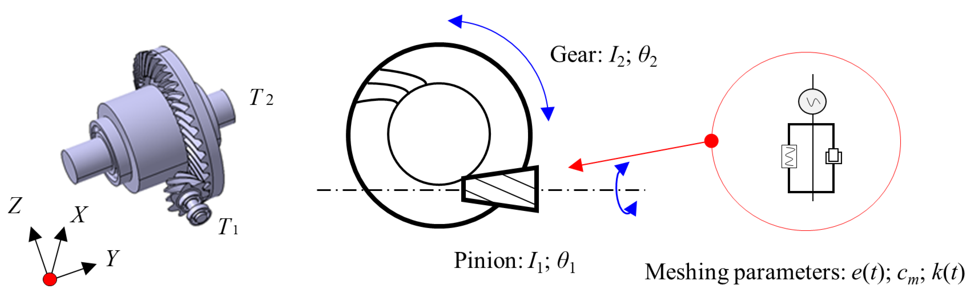
Figure 3.
Machining simulations of hypoid gears: (a) 3D face-milled process showing relative positions of cutter-head and work-piece of the pinion and the gear, (b) generating settings of machine-tool for the pinion, and (c) forming settings of machine-tool for the gear.
Figure 3.
Machining simulations of hypoid gears: (a) 3D face-milled process showing relative positions of cutter-head and work-piece of the pinion and the gear, (b) generating settings of machine-tool for the pinion, and (c) forming settings of machine-tool for the gear.
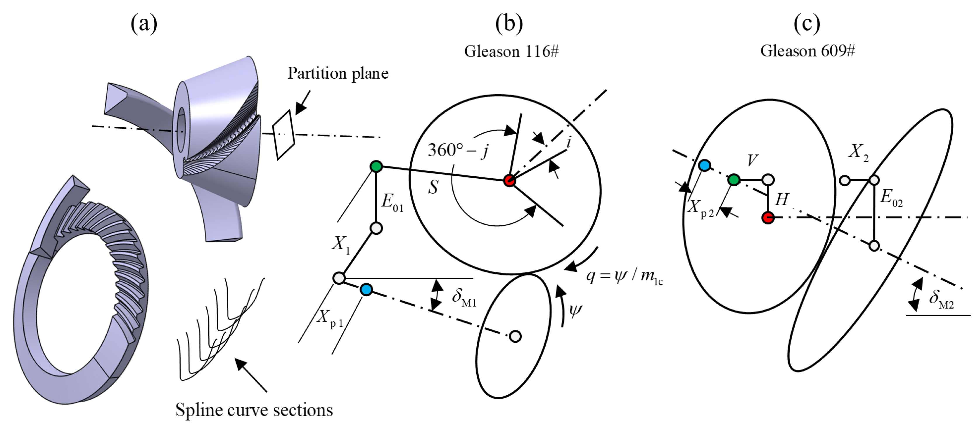
Figure 4.
3D model of hypoid gears and its FE tooth contact model with design specifications and two milling settings as listed in Table 1, Table 2 and Table 3.
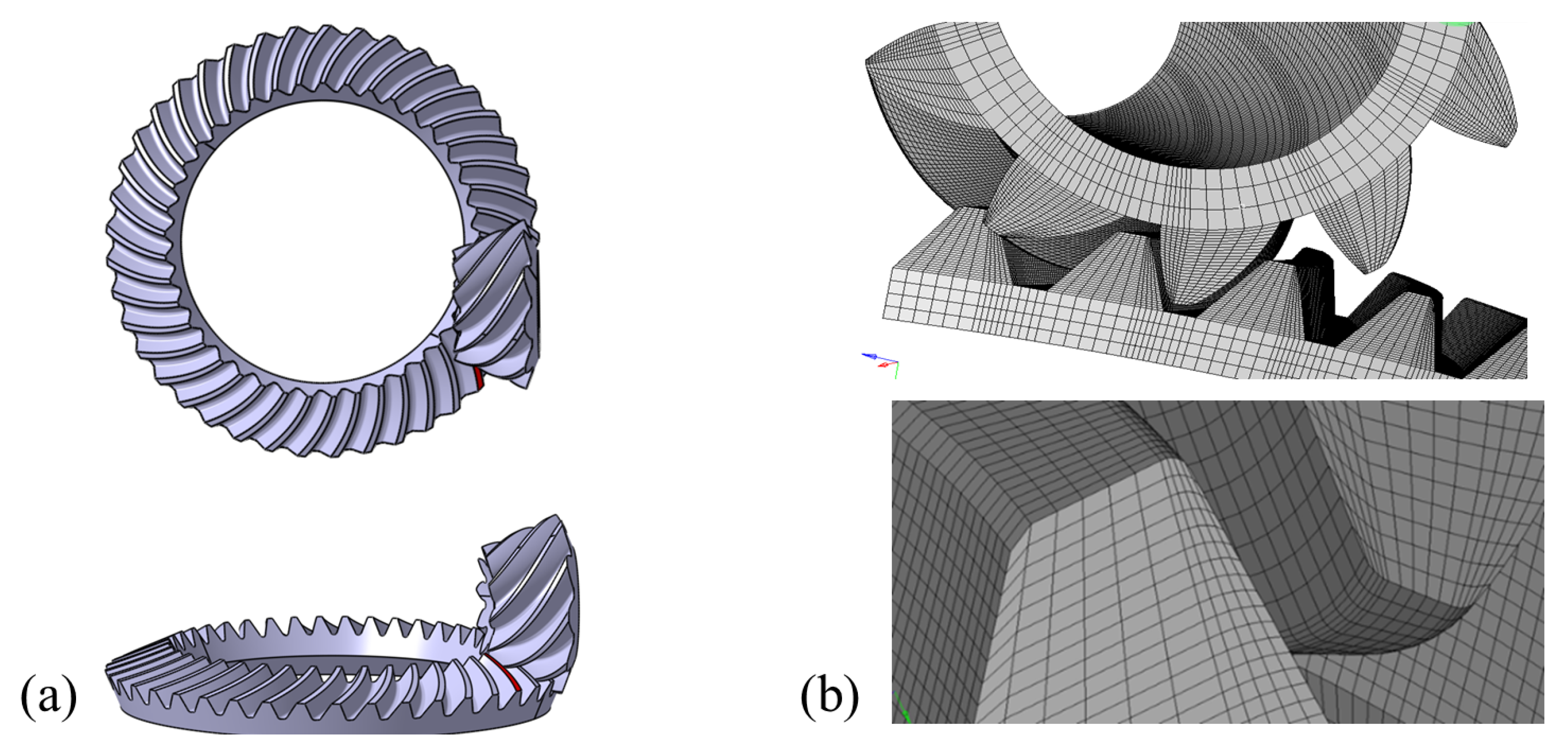
Figure 5.
Physical units of test rig to measure torsional and translational vibrations by rotary encoders and 3-axis accelerometer respectively.
Figure 5.
Physical units of test rig to measure torsional and translational vibrations by rotary encoders and 3-axis accelerometer respectively.
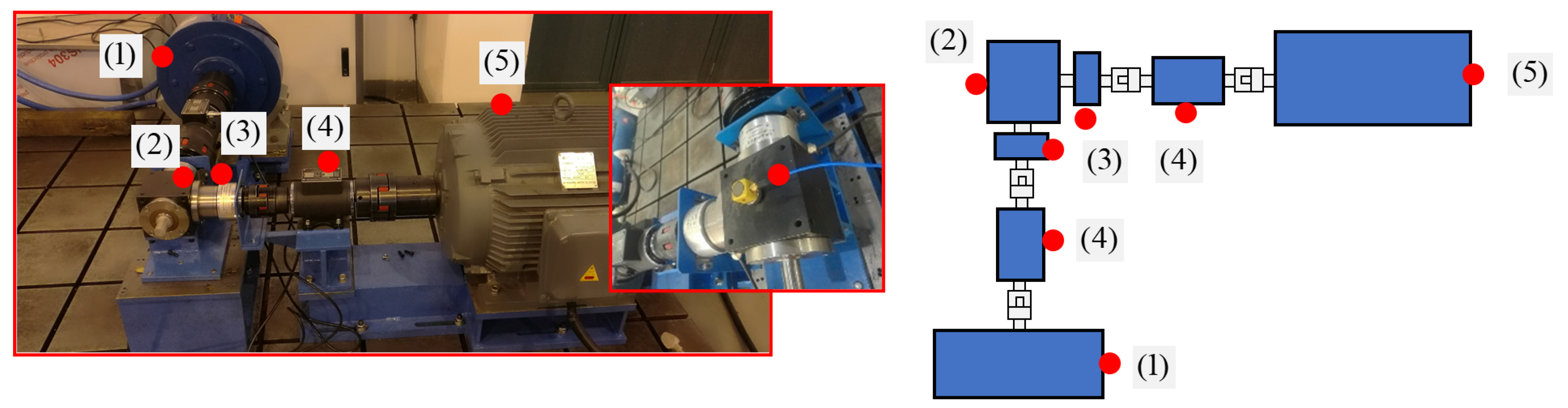
Figure 6.
LTE comparisons between two gear pairs with different contact patterns under different tooth contact conditions.
Figure 6.
LTE comparisons between two gear pairs with different contact patterns under different tooth contact conditions.
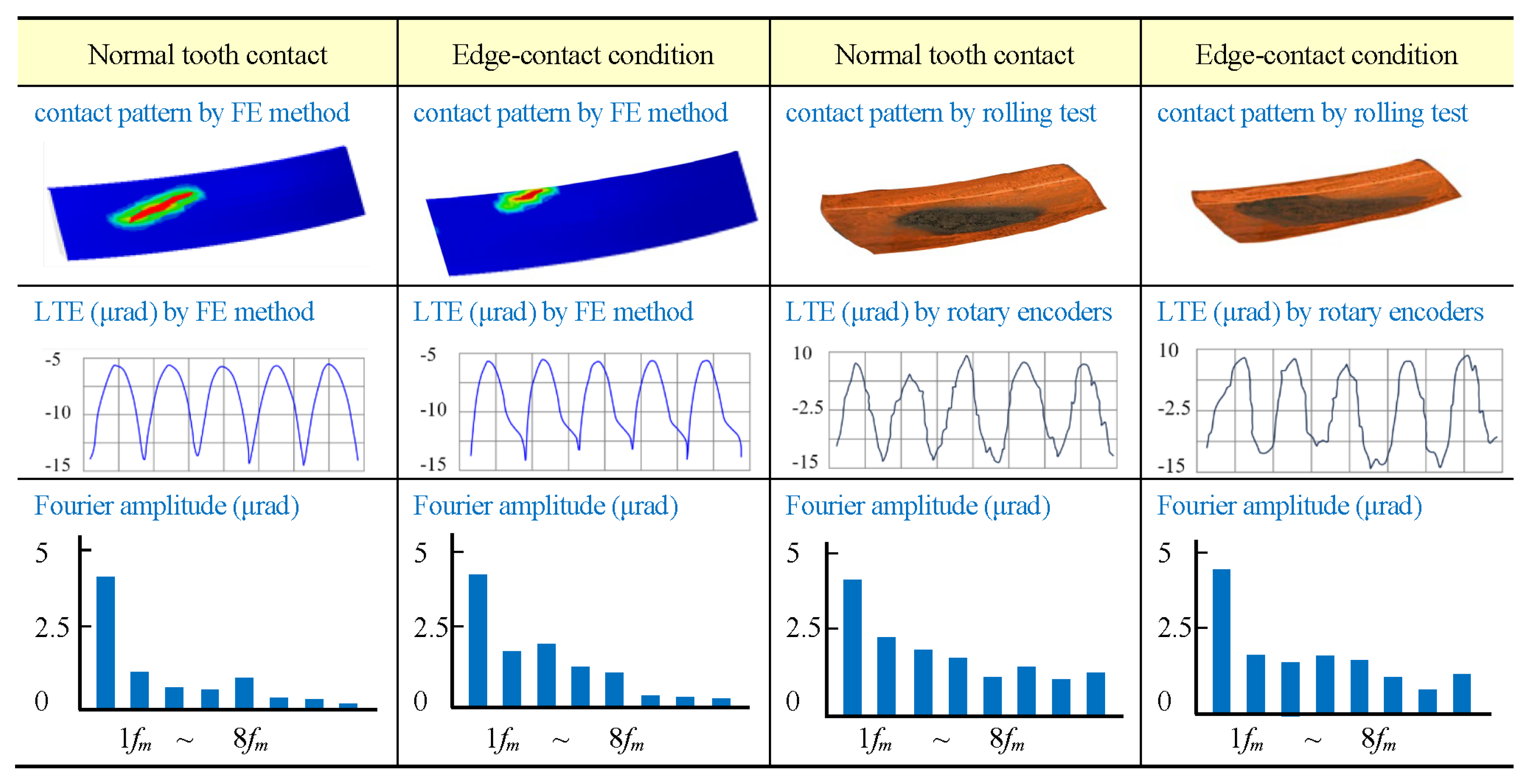
Figure 7.
MS simulation results under two different tooth contact conditions.
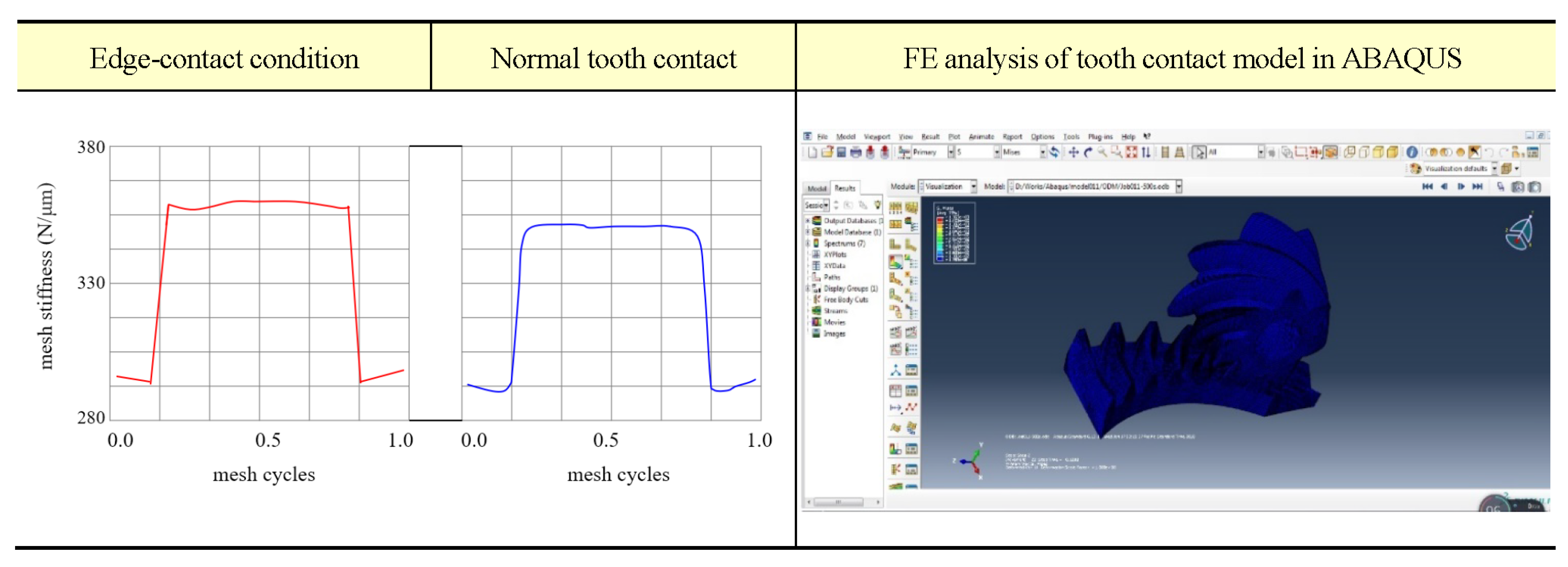
Figure 8.
Harmonic components of MS under two different tooth contact conditions.
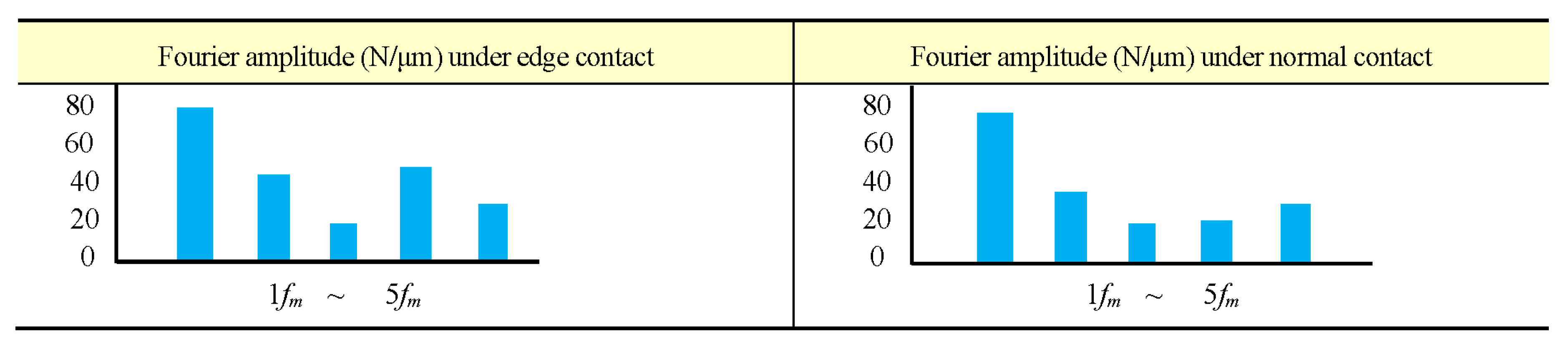
Figure 9.
Dimensionless dynamic TE under two different tooth contact conditions of normal and edge in steady state.
Figure 9.
Dimensionless dynamic TE under two different tooth contact conditions of normal and edge in steady state.
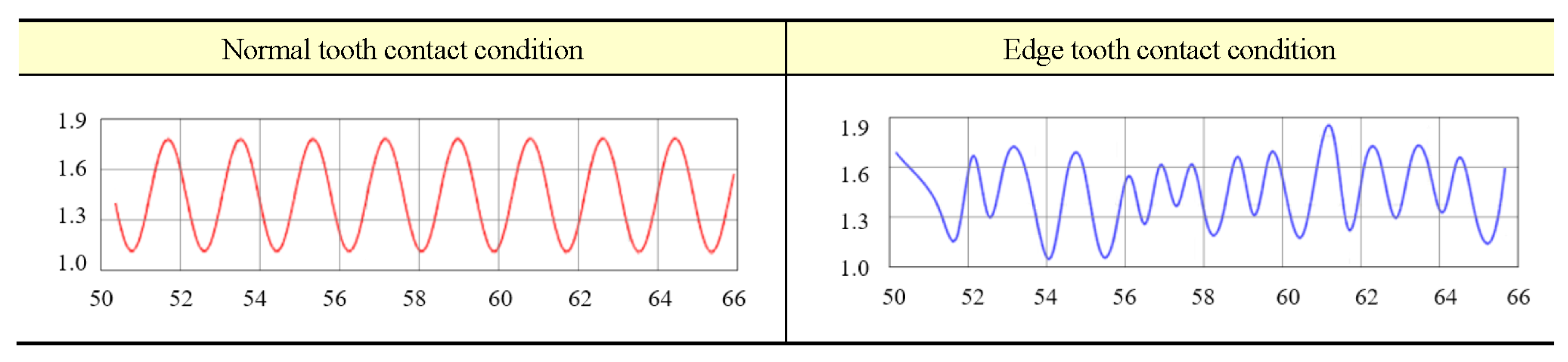
Figure 10.
Angular LRs and SRs between experiments and simulations denoted by blue and red curves respectively.
Figure 10.
Angular LRs and SRs between experiments and simulations denoted by blue and red curves respectively.
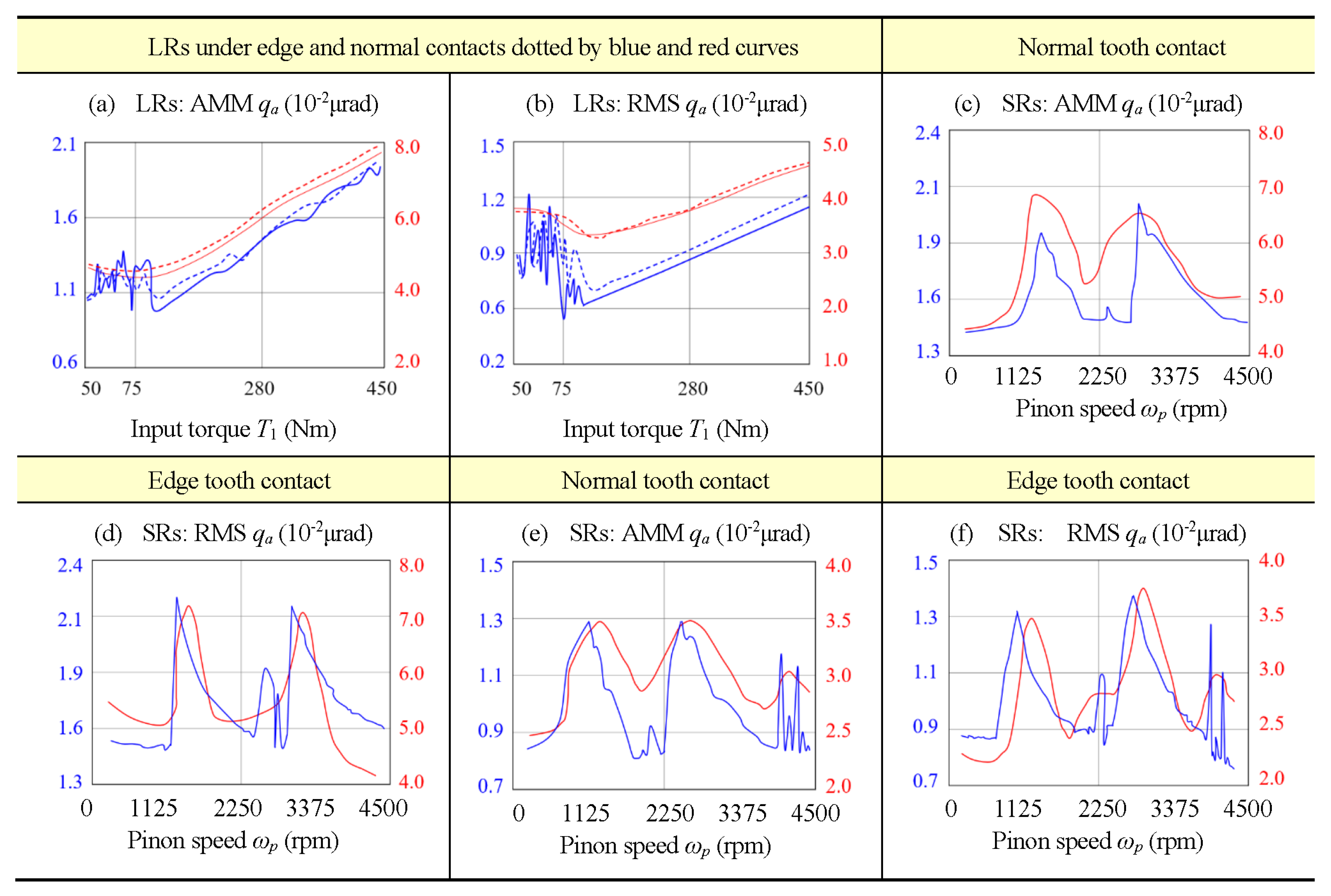
Figure 11.
Measured accelerations in unit of g in x, y and z directions for 5 s at pinion speed 3000 rpm.
Figure 11.
Measured accelerations in unit of g in x, y and z directions for 5 s at pinion speed 3000 rpm.
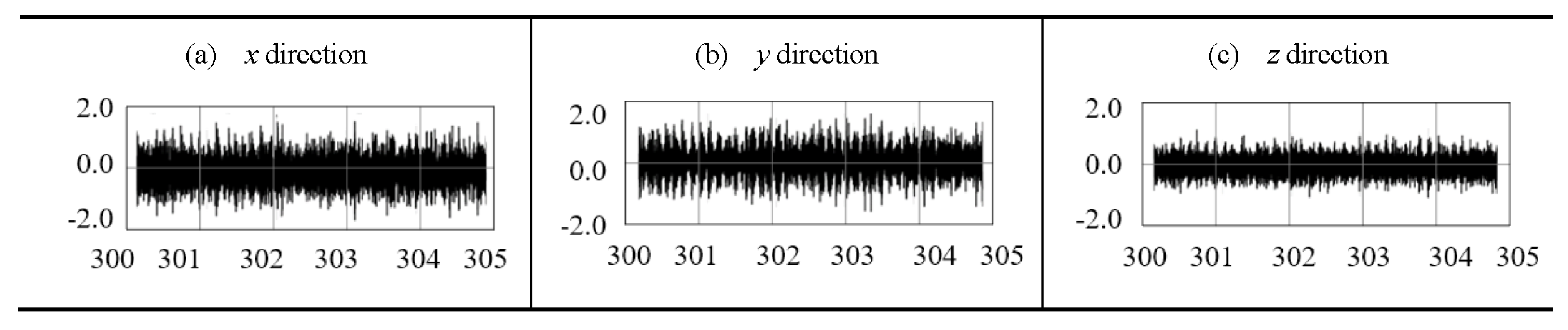
Figure 12.
Primary resonances of first three orders at 1,980 kHz, 3,960 kHz, and 5,940 kHz in x, y, and z directions.
Figure 12.
Primary resonances of first three orders at 1,980 kHz, 3,960 kHz, and 5,940 kHz in x, y, and z directions.
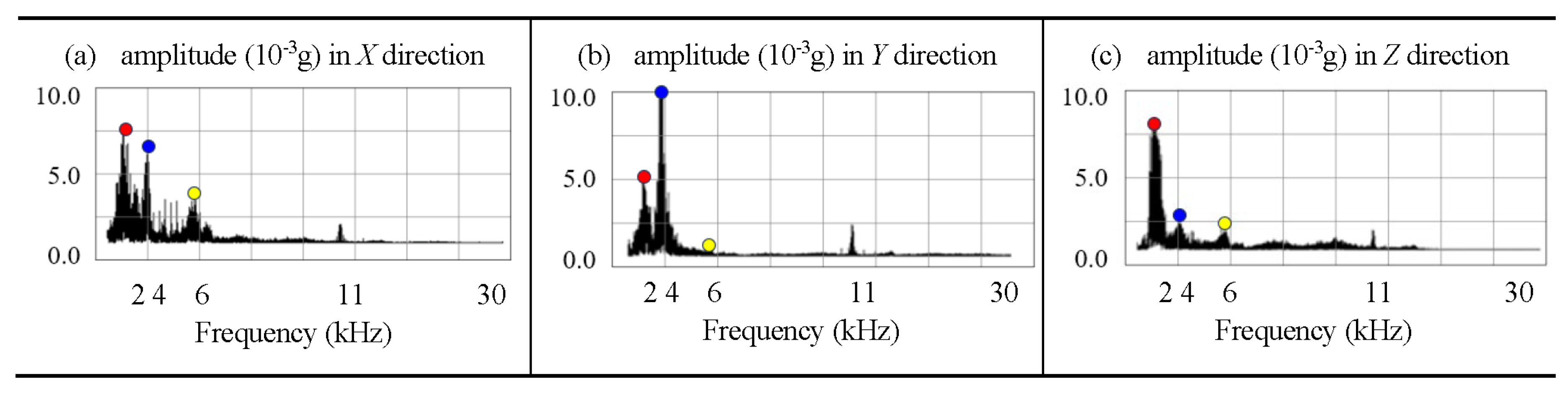
Figure 13.
Translational SRs in RMS at orders of n = 1, 2, 3, and vibrational frequencies .
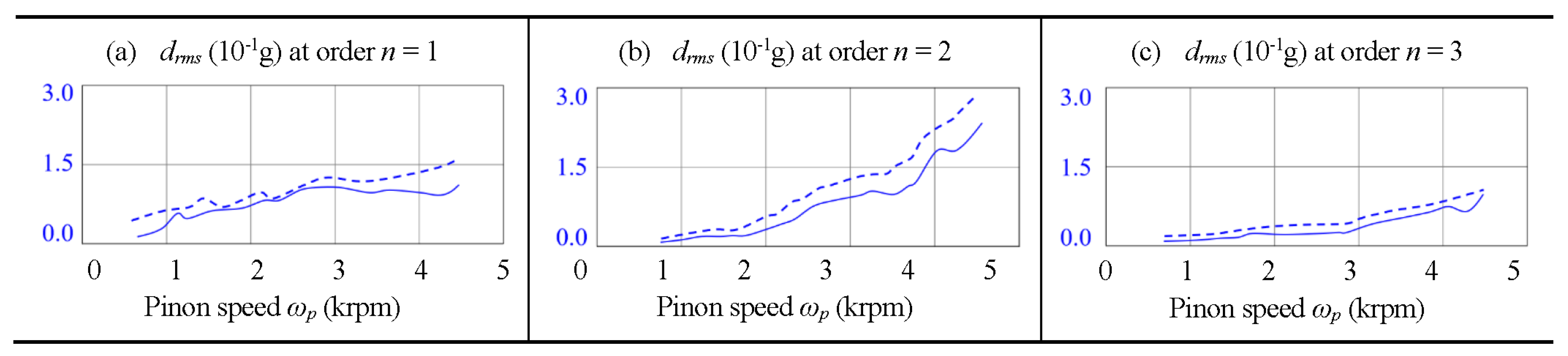

Table 1.
Basic design specifications of the hypoid gear pair 41×11 on the drive side.
| Design Parameters | Symbols | Pinion | Gear | |
| Number of teeth | 11 | 41 | ||
| Spiral direction | Left | Right | ||
| Pitch diameter | N/A | 295.00 | ||
| Shaft offset (mm) | E | 25.40 | ||
| Face width (mm) | 44.57 | 41.00 | ||
| Outer cone diameter (mm) | 156.32 | 273.57 | ||
| Mean spiral angle (deg) | 45.08 | 48.08 | ||
| Pitch cone angle (deg) | 11.82 | 77.92 | ||
| Face cone angle (deg) | 16.18 | 78.57 | ||
| Root cone angle (deg) | 11.17 | 73.45 | ||
| Face cone point | -0.68 | 0.64 | ||
| Pitch cone point | -7.24 | 0.39 | ||
| Root cone point | -1.62 | 0.08 |
Table 2.
Machine-tool settings of gear pair No. 1 in the normal tooth contact condition.
| Settings of machine-tool | Symbols | Pinion | Gear |
| Sliding base | 28.78 | 87.94 | |
| Machine center to back | 2.63 | -3.63 | |
| Flank offset | 24.38 | 76.59 | |
| Machine root angle (deg) | 357.78 | 20.40 | |
| Cradle radius | 117.12 | 25.38, 99.50 | |
| Head-cutter title angle (deg) | i | 18.59 | 0 |
| Head-cutter swivel angle (deg) | j | -43.53 | 0 |
| Head-cutter diameter | 243.08 | 112.95 | |
| Head-cutter blade angle (deg) | 14 | 20 | |
| Roll ratio | 3.67 | 0 | |
| Machining method | generating | forming |
Table 3.
Machine-tool settings of gear pair No. 2 in the tooth edge contact condition.
| Settings of machine-tool | Symbols | Pinion | Gear |
| Sliding base | 23.57 | 87.94 | |
| Machine center to back | -0.86 | -3.63 | |
| Flank offset | 22.39 | 76.59 | |
| Machine root angle (deg) | 358.35 | 20.40 | |
| Cradle radius | 115.68 | 25.38, 99.50 | |
| Head-cutter title angle (deg) | i | 17.95 | 0 |
| Head-cutter swivel angle (deg) | j | -40.67 | 0 |
| Head-cutter diameter | 232.45 | 112.95 | |
| Head-cutter blade angle (deg) | 14 | 20 | |
| Roll ratio | 3.63 | 0 | |
| Machining method | generating | forming |
Disclaimer/Publisher’s Note: The statements, opinions and data contained in all publications are solely those of the individual author(s) and contributor(s) and not of MDPI and/or the editor(s). MDPI and/or the editor(s) disclaim responsibility for any injury to people or property resulting from any ideas, methods, instructions or products referred to in the content. |
© 2025 by the authors. Licensee MDPI, Basel, Switzerland. This article is an open access article distributed under the terms and conditions of the Creative Commons Attribution (CC BY) license (http://creativecommons.org/licenses/by/4.0/).
Copyright: This open access article is published under a Creative Commons CC BY 4.0 license, which permit the free download, distribution, and reuse, provided that the author and preprint are cited in any reuse.


