
Submitted:
15 January 2025
Posted:
16 January 2025
You are already at the latest version
Abstract
A fast-neutral flux generated from a glow gas discharge using a custom-designed source has been proposed to improve the adhesion of PTFE surfaces. The effects of glow discharge parameters and the composition of the working gas on the activation process were evaluated through contact angle measurements and subsequent surface energy calculations. PTFE surfaces treated in an argon atmosphere exhibited the most significant hydrophilic and adhesive properties, achieving a water contact angle as low as 13∘ and surface energy values of 82 mN/m, with an exceptionally high polar component. The optimal effect was observed when the optical spectrum of the plasma showed maximum intensity peaks in the UV range at wavelengths between 310 and 315 nm. The outcomes of this proposed method were then compared with those obtained using conventional industrial techniques for enhancing adhesion.
Keywords:
PTFE
; surface activation
; glow discharge
; fast-neutrals source
; water contact angle
; surface energy
; argon plasma
1. Introduction
Polytetrafluoroethylene (PTFE, also known as Teflon) stands out as the most durable material in the fluoroolefin family, finding widespread use in numerous industries such as mechanical engineering, electrical engineering, medicine, and the food sector [1,2]. Due to its outstanding mechanical and electrophysical characteristics, PTFE has found extensive use in the radiotechnical industry. Materials derived from PTFE have become the benchmark in the production of microwave laminates for printed circuit boards, manufactured by prominent international suppliers of dielectric materials for microwave electronics, such as Rogers [3], Taconic [4], Arlon [5], Nelco, and others. Nevertheless, the high anti-adhesive and hydrophobic nature of PTFE presents substantial obstacles when attempting to metallize it with rolled copper foil, thereby rendering the development of techniques to improve PTFE adhesion a crucial technological challenge.
To tackle the challenge, the fluoropolymer’s surface needs to be modified by changing its morphology and composition [6]. Various techniques can achieve this, including direct chemical processing in gas (or liquid) phases, as well as physicochemical treatments involving corona discharge, ion beams, laser irradiation, ultraviolet light, and other similar approaches.
Adhesion is closely tied to the phenomenon of surface wetting. Investigating changes in the contact angle of wetting and subsequently determining the surface energy value is one of the most straightforward methods available.
As previously noted, the primary cause of PTFE’s chemical inertness is the strong fluorine bonds within its molecule, so improving its adhesive ability can be achieved by breaking these bonds, for example, during the etching process. Teflon is nearly insoluble in most solvents and highly resistant to the action of chemical compounds. However, there is only one group of chemical compounds capable of disrupting the structure of fluorinated polymers — solutions or melts of alkali metals. One of the most common methods for treating the surface of PTFE involves immersing plates into solutions of metal-aromatic complexes based on alkali metals (Li, K, Na) and aromatic hydrocarbons (naphthalene, diphenyl, anthracene, etc.) [7].
The chemical treatment process presents several significant drawbacks. Initially, the use of corrosive solutions may lead to the absorption of alkali metal salts on the surface, resulting in unpredictable changes in the electrical, hydrophilic and other properties of the surface of the material (as depicted in Figure 1, showing the surfaces of the sample both before and after chemical treatment). In addition, handling alkali metals poses substantial safety risks. Furthermore, when a fluoroplastic surface is treated with metalloaromatic complexes, more than 70% of the initial active solution becomes waste. This complex deactivated solution, which contains hazardous substances, eventually ends up in industrial wastewater after neutralization, contributing to increased environmental pollution [8].
An alternative approach involves activating the PTFE surface using gas discharge plasma. Interactions between charged particles, neutral atoms, and surface molecules can result in morphological changes and the creation of novel chemical groups. A key benefit of using plasma treatment to enhance polymer adhesion lies in the minimal thickness of the affected surface layer, allowing the bulk physicochemical properties of the polymer to remain unaltered. The quality of the polymer surface following plasma modification hinges on the characteristics of the gas discharge. Nonetheless, experimentally determining these characteristics is not straightforward, prompting ongoing research into how process variables—such as discharge type, power, exposure duration, working gas pressure, and others—affect the surface properties of polymers. Published findings on this topic are fragmented and sometimes conflicting [9,10,11,12,13,14], underscoring the importance of identifying optimal conditions for plasma treatment of polytetrafluoroethylene surfaces.
Based on literature, there are two primary mechanisms by which plasma interacts with the PTFE surface: the collision of working gas particles with the surface and the impact of ultraviolet radiation generated during a glow discharge [10,11,13,15]. Methods that effectively combine both these mechanisms produce the best results in surface activation. Efficient generation of ultraviolet radiation is achieved through a glow discharge in argon, nitrogen, and nitrogen compounds (such as ammonia). Using Ar/NH3 plasma, the most efficient activation of the PTFE surface (with the smallest water contact angles) has been observed [13]. However, it should be noted that the impact of high-energy gas particles significantly increases surface roughness, leading to a decrease in hydrophilicity [10,12,13,14,16]. Therefore, further efforts to enhance activation should focus on using argon or nitrogen plasma while reducing the energy of the bombarding particles. Unlike ions, fast neutrals do not necessitate compensating for the surface charge when treating dielectrics, thus reducing the occurrence of processing-related defects. Surface processing efficiency significantly improves in the low-pressure regime, reaching down to 0.1 Pa, which makes special requirements on the design of the plasma source.
In this research, we propose using a flux of low-energy neutral atoms generated by a custom-designed fast-neutral source. We investigated the impact of glow discharge parameters and the composition of the working gas on the activation process. The efficiency of the activation was evaluated via contact angle measurements and subsequent surface energy calculations. The outcomes of the fast-neutrals treatment were subsequently compared with those achieved through conventional surface treatment techniques, including corona discharge and chemical treatment.
2. Materials and Methods
2.1. Fast-Neutrals Activation
The source of neutrals can be categorized into three distinct zones: the ion source, the charge exchange zone, and the fast atom beam propagation zone.
The ion source could be a gas discharge plasma featuring a cold cathode [17], microwave excitation [18], or RF inductive excitation [19,20]. Ion neutralization occurs either via charge exchange with atoms or molecules as they traverse the neutral gas region, or through grazing reflection off the surface of the neutralizing electrode.
In systems equipped with a direct neutralization channel (see Figure 2), resonant ion charge exchange dominates. The accelerated ion beam interacts with a gas target generated from the gas flow within the charge exchange channel. A high neutralization coefficient, defined as the ratio of fast neutrals to the total number of atoms and ions of the plasma-forming gas, is attained due to the pressure differential between the channel’s inlet and outlet.
The sliding charge exchange effect is implemented in systems that feature a channel inclined at a small angle relative to the ion beam axis (see Figure 3). This design enables nearly complete neutralization of the initial beam’s ions on the channel walls. The neutralization coefficient in these systems can reach approximately 95% with a channel length of 2.5 cm and an inclination angle of 6° [21].
A source of fast neutrals based on a low-pressure glow discharge utilizes a triode electrode system (see Figure 4). In its simplest form, an electrode composed of individual parallel metal plates serves as a semi-permeable cathode.
The effectiveness of this system depends on the relationship between the width of the cathode plates (H) and the distance between them (L), as well as the ratio between the width of the cathode voltage drop region () and the gap between the cathode plates. An experimentally derived inequality, , represents a critical condition; failure to meet this condition allows plasma to infiltrate the space between the cathode plates, compromising the escape of fast neutrals beyond its boundaries.
The activation of the PTFE sample surface was conducted on an experimental vacuum setup fitted with a high-vacuum pumping system, an automated system for maintaining a specified pressure in the working chamber, and a source of fast neutrals. The residual pressure in the chamber did not exceed Torr.
For processing the sample surfaces, a fast neutral source with dimensions of 150 mm x 350 mm was employed. This source comprises three electrodes: a cathode constructed as a series of 12-mm-wide plates spaced 10 mm apart; an anode that encircles the cathode and is grounded; an additional cathode designed as a rectangular cavity open on one side towards the main cathode (see Figure 4).
The main and additional cathodes together create a quasi-closed volume where electron oscillations occur, facilitating the hollow cathode effect and establishing conditions for electrostatic plasma confinement. The gas discharge plasma is concentrated in the space defined by the cathodes, resulting in higher particle density in the output beam. Furthermore, the hollow cathode effect reduces the minimum pressure required for sustaining stable discharge in the plasma-forming gas introduced into the source volume. A negative voltage is applied to both the main and additional cathodes.
Figure 5 displays a photograph of the process chamber with a glowing discharge. In the foreground is the substrate holder with the sample, while in the background is the grid of cathode plates. It can be seen that the glow discharge remains confined within the ion source and does not make direct contact with the sample.
A notable aspect of the described system is that ions undergo recombination within a symmetrical potential well created by the cathode. The energy of the fast neutral is dictated by the potential difference between the location of ion generation and the site of its neutralization. Given the symmetry of the potential well, ions are unable to escape with energies exceeding thermal levels. Consequently, the output beam from the considered source includes almost no high-energy ions.
Another important feature is that the plate cathode impedes the flow of gas through it, particularly at low pressures when the gas flow exhibits molecular behavior. Under conditions where gas is injected into the source and continuously pumped, this creates a pressure gradient, significantly lowering the pressure in the process chamber while maintaining adequate pressure inside the source for stable discharge operation (see Figure 6).
The fast neutrals source is powered by an APEL-IS-5000A (Prikladnaya Electronica, Tomsk, Russia) unit with the following characteristics (output power 2 kW, output voltage range 0.2-5.0 kV, maximum current 1 A).
2.2. Activation by Corona Discharge
The surface of the PTFE samples was activated using a setup designed for processing fluoroplastic tape up to 200 mm wide. Samples measuring 1 mm in thickness and 100x250 mm2 in size were treated using a standard procedure at atmospheric pressure in corona discharge plasma with a two-electrode system . The upper corona electrode consists of a series of evenly spaced metal needles positioned 5 mm apart. The distance between the sample and the upper electrode was 20 mm, the applied voltage was 30 kV, and the processing time was 30 seconds, with the sample moving beneath the corona electrode at a speed of 0.6 m/min.
2.3. Chemical Activation
In this study, the activation of the PTFE surface was conducted using a sodium-naphthalene complex solution. This complex contains metallic sodium and naphthalene dissolved in tetrahydrofuran, mixed in the following weight proportions: tetrahydrofuran - 88.5 wt%, naphthalene - 12.8 wt%, metallic sodium - 4.6 wt%. The processing of fluoroplastic samples involved several steps. First, the plates were degreased by immersion in gasoline-solvent, followed by drying at 35°C for 15 minutes. Then, the parts were submerged in a container with the sodium-naphthalene complex for 30 seconds at C. Subsequently, the treated parts were rinsed by immersion in acetone for 1 minute at C, followed by rinsing under running water for 20 minutes. Finally, they were dried at room temperature for 10 hours.
2.4. Water Contact Angle Measurement
To assess the hydrophilicity of the PTFE surface, water contact angle (WCA) measurements were taken at the interface between distilled water and the polymer. Using a dispenser drops of 1 ml were placed on the surface at varying time intervals after the activation (from 0 minutes to 24 hours). An example of the contact angle before (WCA0) and after the activation (WCAf) is shown in Figure 7. For untreated PTFE, the WCA0 value typically falls within the range of 110° to 130°.
2.5. Plasma Optical Spectra Measurements
To measure optical spectra, the study employs the ISM3600 spectrometer [22], which features a spectral line database enabling the determination of the elemental and ionic composition of the gas discharge. The spectrometer is capable of recording optical radiation spectra within the range of 200-1000 nm, with a spectral resolution of no more than nm in the visible spectrum. The optical signal produced by the plasma is conveyed from the vacuum chamber using a quartz fiber optic cable with a diameter of 0.4 mm.
2.6. Microwave Parameters Measurements
To examine the effect of various surface treatments on the dielectric properties of PTFE, the dielectric constant () and the dielectric loss tangent () were measured at a frequency of 10 GHz using a split-cylinder resonator based on Kent’s method [23]. Detailed information about the test fixture can be found in Ref. [24].
3. Results and Discussion
3.1. Glow Discharge Activation
To determine the optimal conditions for activating the PTFE surface, a series of experiments involving sample processing in glow discharge plasma was conducted. Initially, argon was selected as the working gas due to numerous literature references. The study was performed under a stabilized discharge current of 10 mA. The lower limit of the pressure range was set at Torr, which ensured stable maintenance of the discharge.
The impact of the working gas pressure is illustrated in Figure 8. As evident from the presented dependence, an increase in pressure results in an increase in the WCA. This effect can be attributed to the fact that, according to Paschen’s law, an increase in pressure causes a decrease in voltage and discharge power (as shown in Table 1). Consequently, this reduction in power leads to a decrease in the intensity of plasma radiation, particularly in the UV spectrum. Additionally, an elevated argon concentration reduces the mean free path of ions and fast neutrals due to increased elastic collisions with gas molecules, thereby diminishing their physical impact on the sample surface.
Figure 9 depicts the relationship between the contact angle and the discharge power. The experiments were performed at a pressure of Torr. The dependence reveals a pronounced minimum: as the power rises, the wetting angle decreases to 16°, reached at a discharge voltage of 410 V and a current of 15 mA.
The study of the effect of surface treatment duration was conducted at an argon pressure of Torr, a voltage of 410 V, and a discharge current of 15 mA. The results presented in Figure 10 indicate that the maximum effect is achieved within 10 minutes of treatment, during which the contact angle decreases from 114° to 16°. Prolonged treatment further reduces the angle down to 13° at a duration of 20 minutes.
A study of the dynamics of the contact angle recovery reveals that the degradation of hydrophilic properties commences after one hour, with the contact angle nearly doubling from 13° to 29° within the initial 48 hours. However, it takes six days for the contact angle values to approach those observed following treatment in a corona discharge.
A series of analogous experiments were conducted using various gases such as N2, O2, He, CF4 (Freon 134A), and mixtures of Ar and O2 in different proportions. Figure 12 presents the measured average WCA values after each treatment. PTFE surfaces treated in an argon atmosphere exhibited the most effective hydrophilic properties, achieving a WCA of 13°. In contrast, the use of reactive gases—nitrogen, oxygen, and freon—increased the WCA to 31°, 80°, and 78°, respectively. Adding minor concentrations of oxygen (1% to 5%) to argon significantly impaired the hydrophilic characteristics. Moreover, a series of trials with neon contradicted the idea that inert gases are ideal for PTFE processing, as the WCA rose to 44°.
Figure 13 presents the results of optical emission spectroscopy of discharge plasma for various gases used in the treatment of the PTFE surface within the wavelength range of 260–400 nm. It is evident that gases yielding the minimum WCA values (argon and nitrogen) display peaks in the intensity of spectral lines in the UV region at wavelengths around 310–315 nm. Meanwhile, adding small concentrations of oxygen to argon shifts ionization processes from argon to oxygen, resulting in a sharp decrease in the intensity of UV plasma radiation and an increase in the contact angle from 13° to 70°–80°. These observations confirm the hypothesis that plasma radiation in the UV wavelength range contributes to the breakdown of C-F bonds.
3.2. Surface Energy
To theoretically describe the adhesive properties of the material’s surface under study, it is recommended to evaluate the degree of its wettability. Intermolecular interactions at the boundary between the solid and liquid phases can be determined by experimentally measuring the contact angle (). The surface tensions of the phases at the interface are related to the cosine of the wetting angle via Young’s equation [25]:
where is the equilibrium surface tension of the solid, is the interfacial surface tension at the solid-liquid boundary, and is the equilibrium surface tension of the liquid. To precisely determine the magnitude of surface energy, it is crucial to consider the nature of the forces acting at the phase contact. Adhesive and cohesive forces stem from intermolecular interactions, commonly classified into van der Waals and polar interactions, resulting in the division of surface energy into respective components. This approach is utilized in the Owens-Wendt-Rabel-Kaelble (OWRK) interfacial interaction model, facilitating the estimation of the surface energy components of solids based on experimentally measured WCAs with test liquids [26]:
where , are the dispersion and polar components of the surface energy of a liquid, and , are the dispersion and polar components of the surface energy of a solid.
The WCA of the samples was measured using working liquids with known polar and dispersion components of surface tension: water, ethyl alcohol, and glycerol (see Table 2). Measurements with different working liquids were conducted simultaneously on samples activated within a single process. The results of these measurements are summarized in Table 3.
The surface energy value of the activated polytetrafluoroethylene sample, along with its polar and dispersion components , was determined by constructing an approximation dependence corresponding to Equation 2. The example shown in Figure 14 demonstrates the method for calculating these parameters for a sample processed in glow-discharge plasma.
Table 4 presents the results of determining the surface tension components of PTFE sheets activated by various methods. The standard surface energy value for pure (non-activated) PTFE is 18 mN/m, with the polar component assumed to be absent. Depending on the treatment type, the values of the surface energy components vary widely, but the polar component value is generally decisive and enables characterization of the treatment method’s efficiency. Notably, the highest surface energy value was achieved after treating the PTFE surface in an argon discharge (82.3 mN/m), with an exceptionally high polar component. This suggests the formation of polar groups (such as hydroxyl or carboxyl) on the surface.
It is worth noting that the use of test markers or inks, commonly employed in the polymer industry to measure surface energy, only permits an evaluation within the range of 30–60 mN/m (Accu Dyne Test). This limited scope is inadequate for investigating the impact of glow discharge on the properties of the PTFE surface.
The summarized results for the water contact angle (WCAf) and surface energy for various activation techniques are presented in Figure 15.
3.3. Microwave Properties
The microwave properties of the activated samples were examined (see Table 5). It can be concluded that chemical treatment marginally modified the dielectric properties, whereas the other techniques did not induce any detectable alterations.
4. Conclusions
The study showed that treating the PTFE surface in glow discharge plasma using a proposed fast neutral source can greatly enhance its hydrophilic and adhesive properties compared to conventional chemical methods and corona discharge activation, reaching surface energy levels of 82 mN/m with a water contact angle of 13°. The peak effect is achieved during plasma treatment in an argon and nitrogen environment, where the optical spectrum exhibits maximum intensity peaks in the UV region at wavelengths ranging from 310 to 315 nm.
Author Contributions
Conceptualization, A.K. and D.K.; methodology, A.K. and D.K.; validation, A.K. and A.G.; software A.T.; formal analysis, D.K.; investigation, D.K., I.N., A.T. and A.G.; resources, A.K.; data curation, A.G.; writing—original draft preparation, D.K. ; writing—review and editing, D.K.; visualization, D.K.; supervision, R.P.; project administration, R.P.; funding acquisition, A.K., A.A. and A.G. All authors have read and agreed to the published version of the manuscript.
Funding
This research was funded by The Ministry of Education and Science of the Russian Federation within the framework of the state assignment No. 075-01438-22-07 of 28.10.2022 (FSEE- 2022-0019).
Conflicts of Interest
The authors declare no conflicts of interest.
References
- Dhanumalayan, E.; Joshi, G.M. Performance properties and applications of polytetrafluoroethylene (PTFE)—a review. Advanced Composites and Hybrid Materials 2018, 1, 247–268. [CrossRef]
- Ebnesajjad, S. Expanded PTFE applications handbook: technology, manufacturing and applications; William Andrew, 2016.
- Rogers corporation. RO3000 Series Laminates. https://www.rogerscorp.com/advanced-electronics-solutions/ro3000-series-laminates, 2024. [Online; accessed 12-December-2024].
- Santhanam, N. Low cost, high performance RF substrates. In Proceedings of the 1999 IEEE MTT-S International Topical Symposium on Technologies for Wireless Applications (Cat. No. 99TH8390). IEEE, 1999, pp. 65–68.
- Hornung, R.R.; Frankosky, J.C. Microwave laminate material considerations for multilayer applications. In Proceedings of the 2007 European Microwave Conference. IEEE, 2007, pp. 1425–1428.
- Schonhorn, H.; Ryan, F.W. Adhesion of polytetrafluoroethylene. The Journal of Adhesion 1969, 1, 43–47. [CrossRef]
- Roina, Y.; Gonçalves, A.M.; Fregnaux, M.; Auber, F.; Herlem, G. Sodium naphthalenide diglyme solution for etching ptfe, characterizations and molecular modelization. ChemistrySelect 2022, 7, e202200153. [CrossRef]
- Gabriel, M.; Dahm, M.; Vahl, C.F. Wet-chemical approach for the cell-adhesive modification of polytetrafluoroethylene. Biomedical Materials 2011, 6, 035007. [CrossRef]
- Primc, G. Recent advances in surface activation of polytetrafluoroethylene (PTFE) by gaseous plasma treatments. Polymers 2020, 12, 2295. [CrossRef]
- Liu, C.; Wu, J.; Ren, L.; Tong, J.; Li, J.; Cui, N.; Brown, N.; Meenan, B. Comparative study on the effect of RF and DBD plasma treatment on PTFE surface modification. Materials Chemistry and Physics 2004, 85, 340–346. [CrossRef]
- Wilson, D.; Williams, R.; Pond, R. Plasma modification of PTFE surfaces. Part I: Surfaces immediately following plasma treatment. Surface and Interface Analysis: An International Journal devoted to the development and application of techniques for the analysis of surfaces, interfaces and thin films 2001, 31, 385–396. [CrossRef]
- Kolská, Z.; Řezníčková, A.; Hnatowicz, V.; Švorčík, V. PTFE surface modification by Ar plasma and its characterization. Vacuum 2012, 86, 643–647. [CrossRef]
- Hai, W.; Hi, T.; Shimizu, K.; Yajima, T. Preparation of a super hydrophilic polytetrafluoroethylene surface using a gaseous ammonia-water low-temperature plasma. Journal of Photopolymer Science and Technology 2015, 28, 479–483. [CrossRef]
- Hong, S.H.; Kim, T.H.; Choi, S. Hydrophilic surface modification of polytetrafluoroethylene film with gliding arc plasma. Applied Science and Convergence Technology 2019, 28, 101–106. [CrossRef]
- Nguyen, H.D.; Yajima, T. A spectroscopic study on argon-ammonia water gaseous plasma super-hydrophilizing polytetrafluoroethylene. Journal of Photopolymer Science and Technology 2017, 30, 325–330. [CrossRef]
- Bruce, R.; Weilnboeck, F.; Lin, T.; Phaneuf, R.; Oehrlein, G.; Long, B.; Willson, C.; Vegh, J.; Nest, D.; Graves, D. Relationship between nanoscale roughness and ion-damaged layer in argon plasma exposed polystyrene films. Journal of Applied Physics 2010, 107. [CrossRef]
- Shimokawa, F.; Tanaka, H.; Uenishi, Y.; Sawada, R. Reactive–fast-atom beam etching of GaAs using Cl2 gas. Journal of applied physics 1989, 66, 2613–2618. [CrossRef]
- Mizutani, T.; Nishimatsu, S. Sputtering yield and radiation damage by neutral beam bombardment. Journal of Vacuum Science & Technology A: Vacuum, Surfaces, and Films 1988, 6, 1417–1420.
- Panda, S.; Economou, D.J.; Chen, L. Anisotropic etching of polymer films by high energy ( 100s of eV) oxygen atom neutral beams. Journal of Vacuum Science & Technology A: Vacuum, Surfaces, and Films 2001, 19, 398–404.
- Samukawa, S.; Sakamoto, K.; Ichiki, K. Generating high-efficiency neutral beams by using negative ions in an inductively coupled plasma source. Journal of Vacuum Science & Technology A: Vacuum, Surfaces, and Films 2002, 20, 1566–1573.
- Degtyarev, A.; Kudrya, V.; Maishev, Y.P. Mathematical simulation of an inclined neutralization channel for a plasma source of neutral beams. Russian Microelectronics 2009, 38, 171–179. [CrossRef]
- Kostrin, D.; Oukhov, A. Hardware-Software Spectrometric Complex For Research Of The Parameters Of Light-Emitting Diodes. Biotekhnosphera 2013, pp. 21–25. In Russian.
- Kent, G. Nondestructive permittivity measurement of substrates. IEEE Transactions on Instrumentation and Measurement 1996, 45, 102–106. [CrossRef]
- Gagarin, A.; Tsyganova, D.; Altynnikov, A.; Komlev, A.; Platonov, R. An Adaptation of the Split-Cylinder Resonator Method for Measuring the Microwave Properties of Thin Ferroelectric Films in a “Thin Film—Substrate” Structure. Sensors 2024, 24, 755. [CrossRef]
- Young, T. An essay on the cohesion of fluids. Philosophical transactions of the royal society of London 1805, pp. 65–87.
- Owens, D.K.; Wendt, R. Estimation of the surface free energy of polymers. Journal of applied polymer science 1969, 13, 1741–1747. [CrossRef]
- Palencia, M. Surface free energy of solids by contact angle measurements. J. Sci. Technol. Appl 2017, 2, 84–93. [CrossRef]
Figure 1.
Photo of the PTFE surface: (a) – before chemical activation; (b) – after chemical activation.
Figure 1.
Photo of the PTFE surface: (a) – before chemical activation; (b) – after chemical activation.
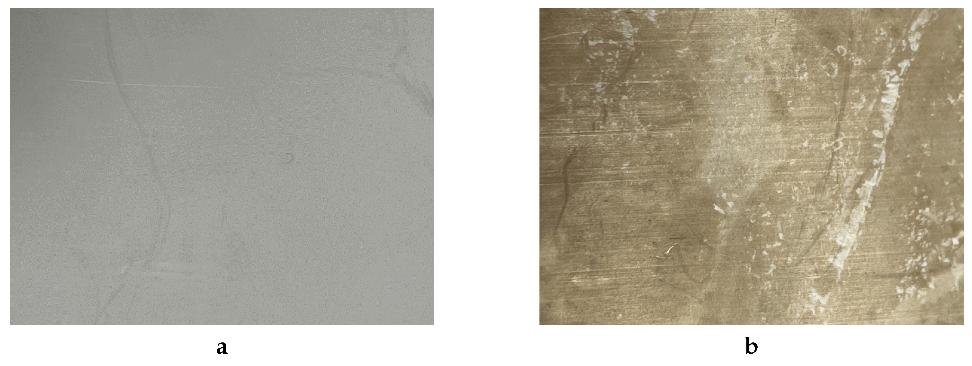
Figure 2.
Schematic diagram of a fast neutral source with a straight channel.
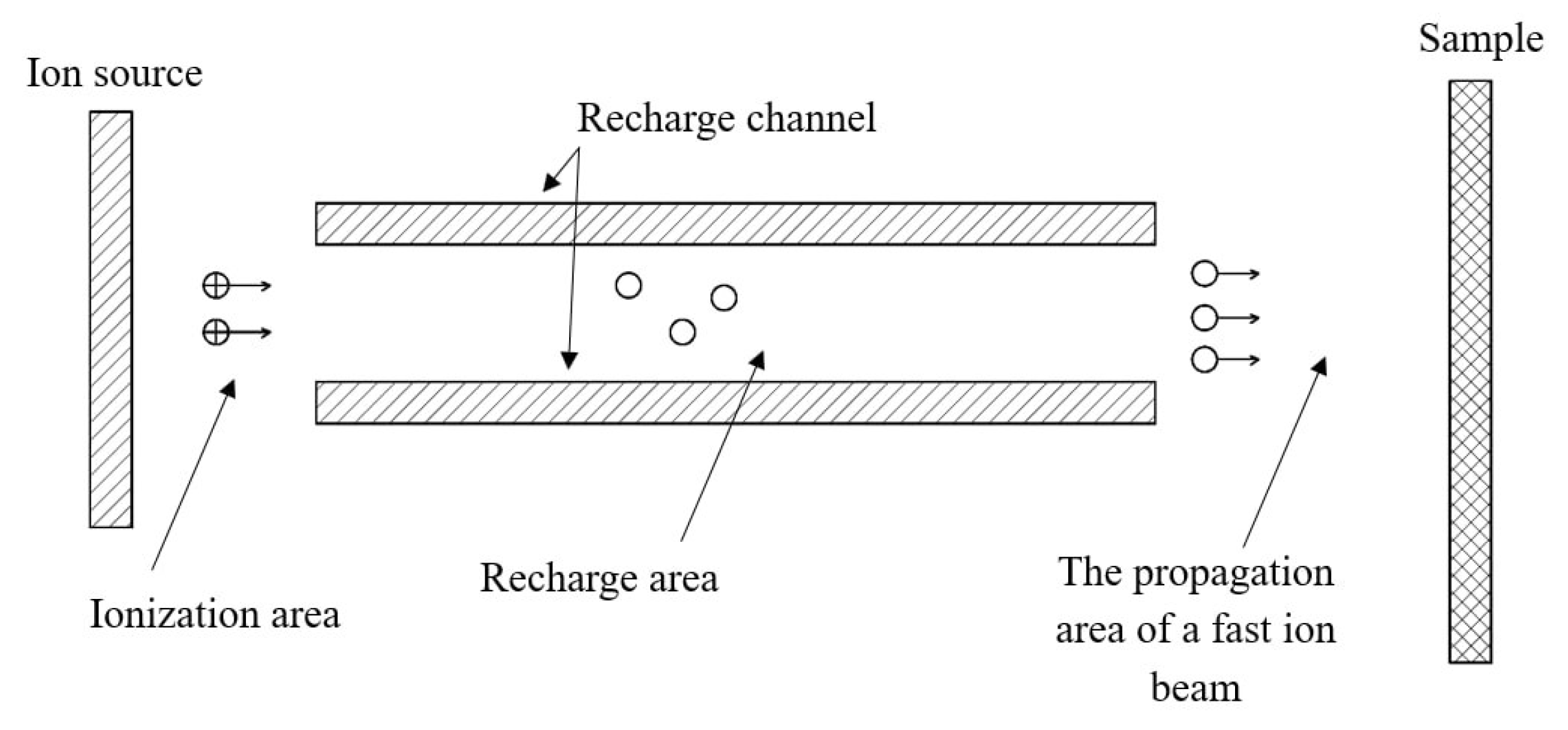
Figure 3.
Schematic diagram of a fast neutral source with an inclined channel.
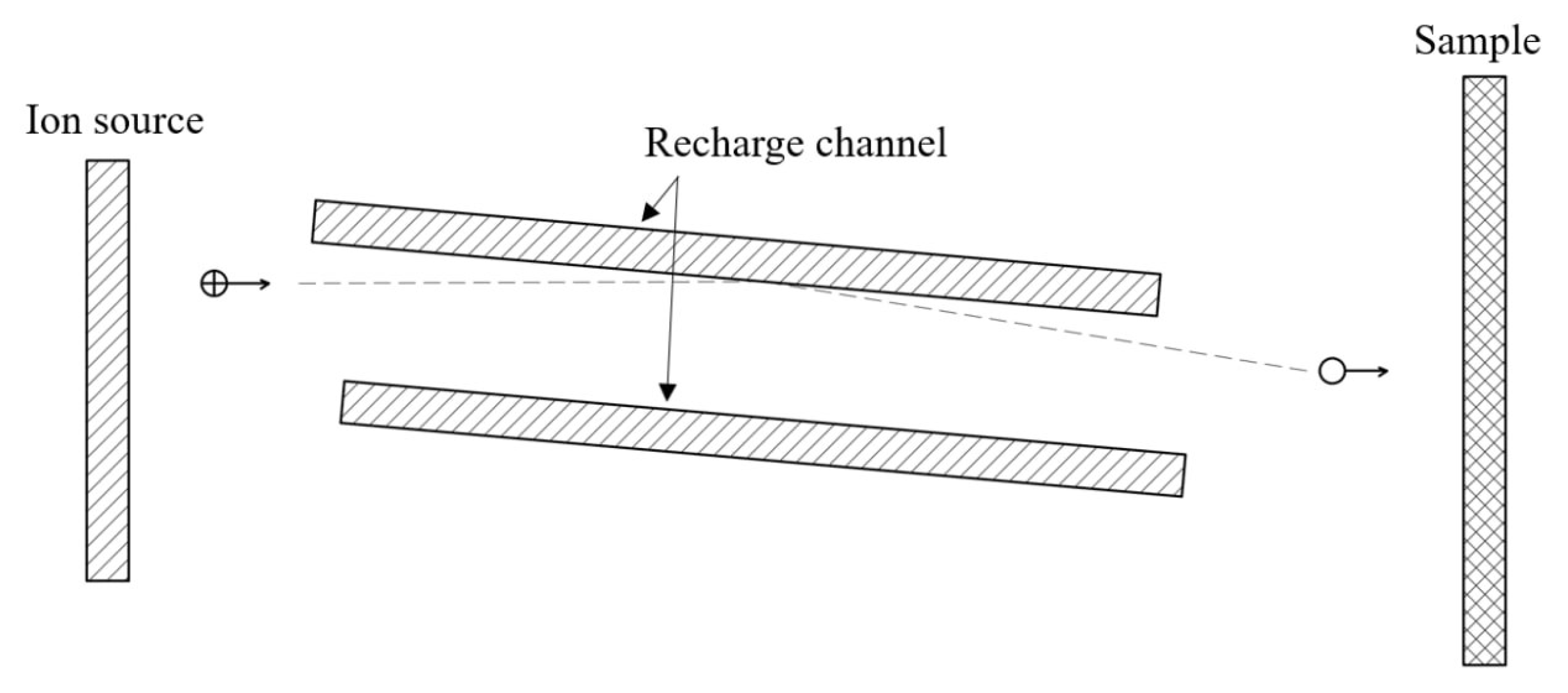
Figure 4.
Schematic diagram of the fast neutral source.
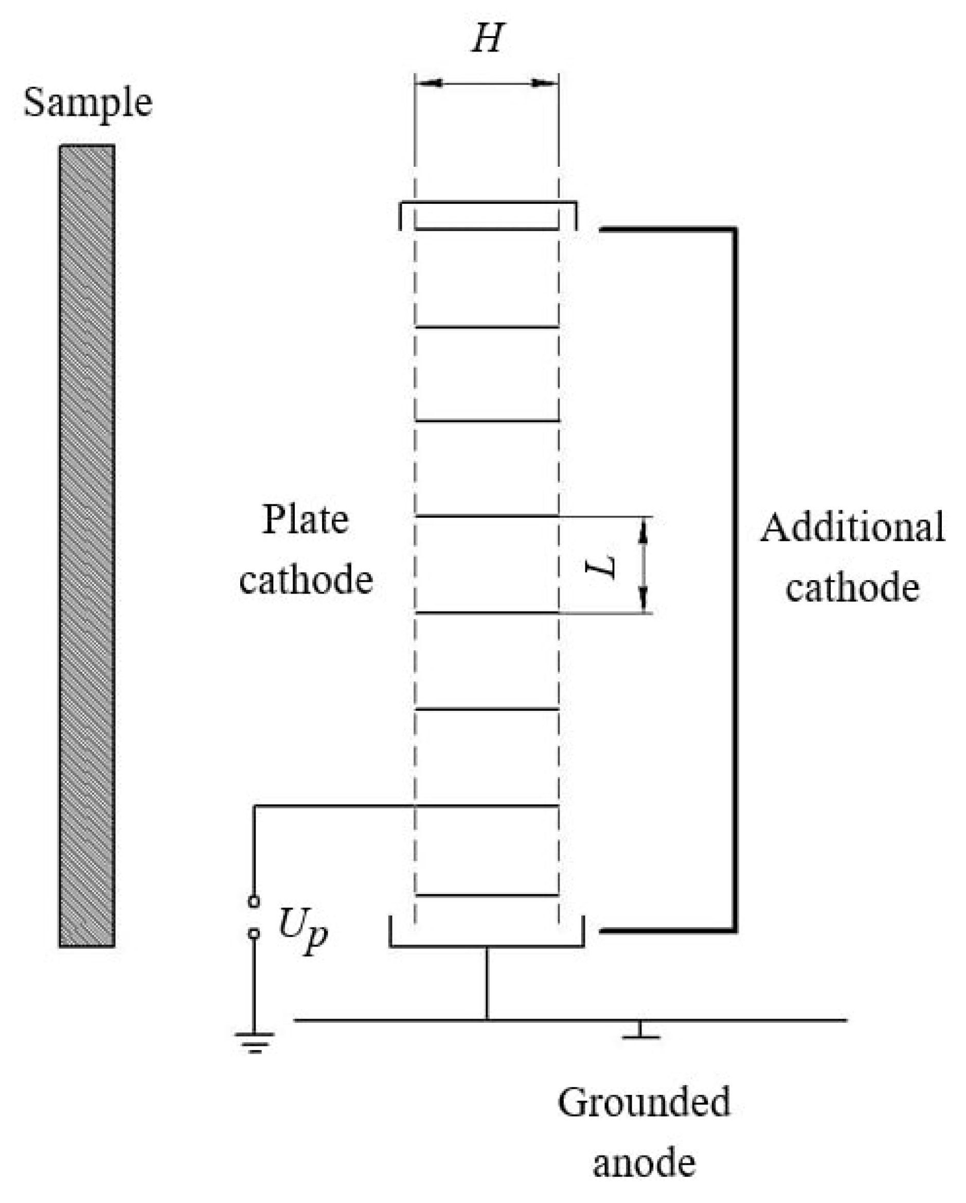
Figure 5.
Photo of the process chamber with fast-neutrals source and sample holder.
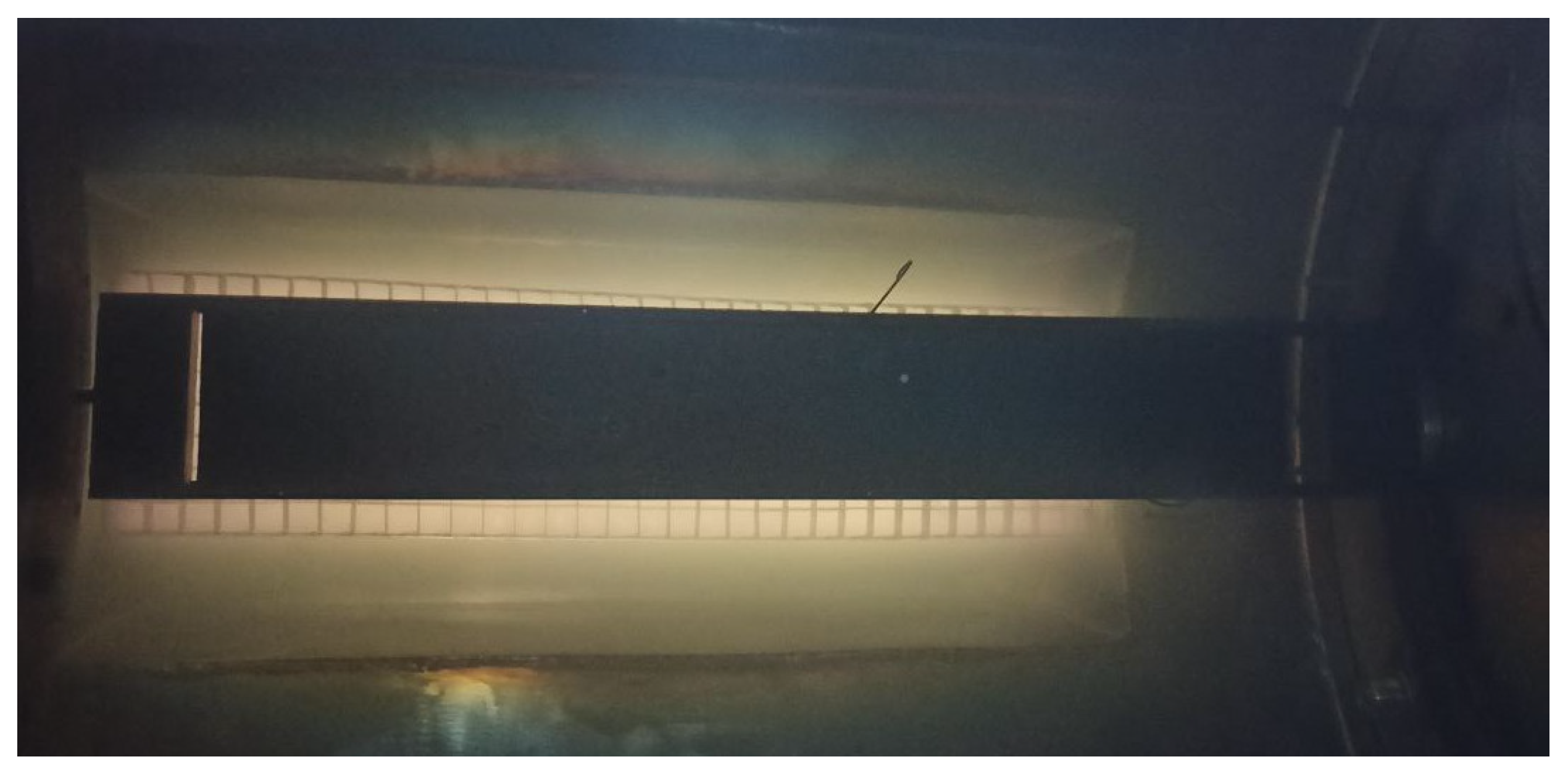
Figure 6.
Dependence of the pressure inside the source on the pressure in the process chamber.
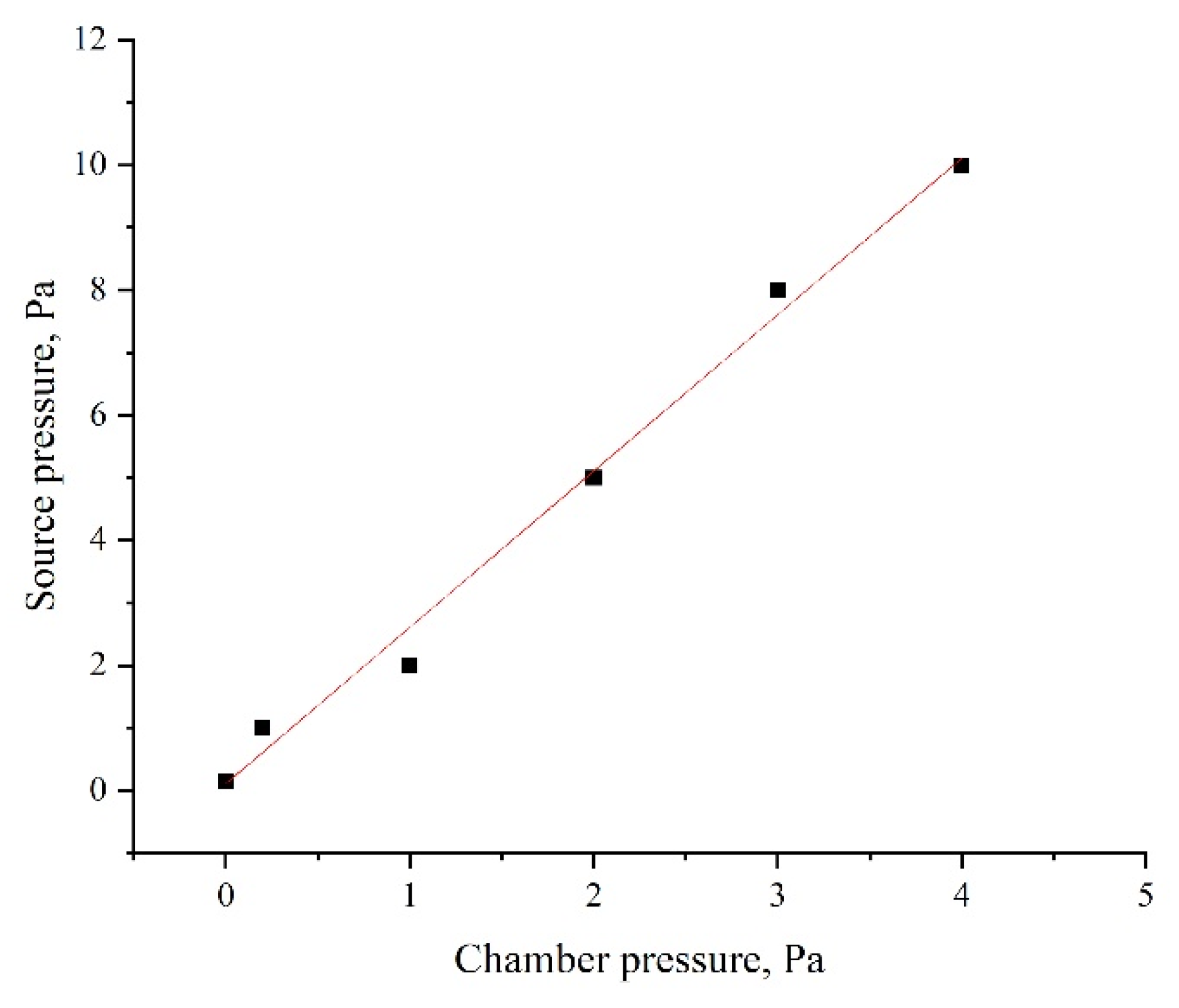
Figure 7.
Examples of results of measuring the water contact angle: (a) – untreated PTFE ; (b) – after glow discharge activation .
Figure 7.
Examples of results of measuring the water contact angle: (a) – untreated PTFE ; (b) – after glow discharge activation .
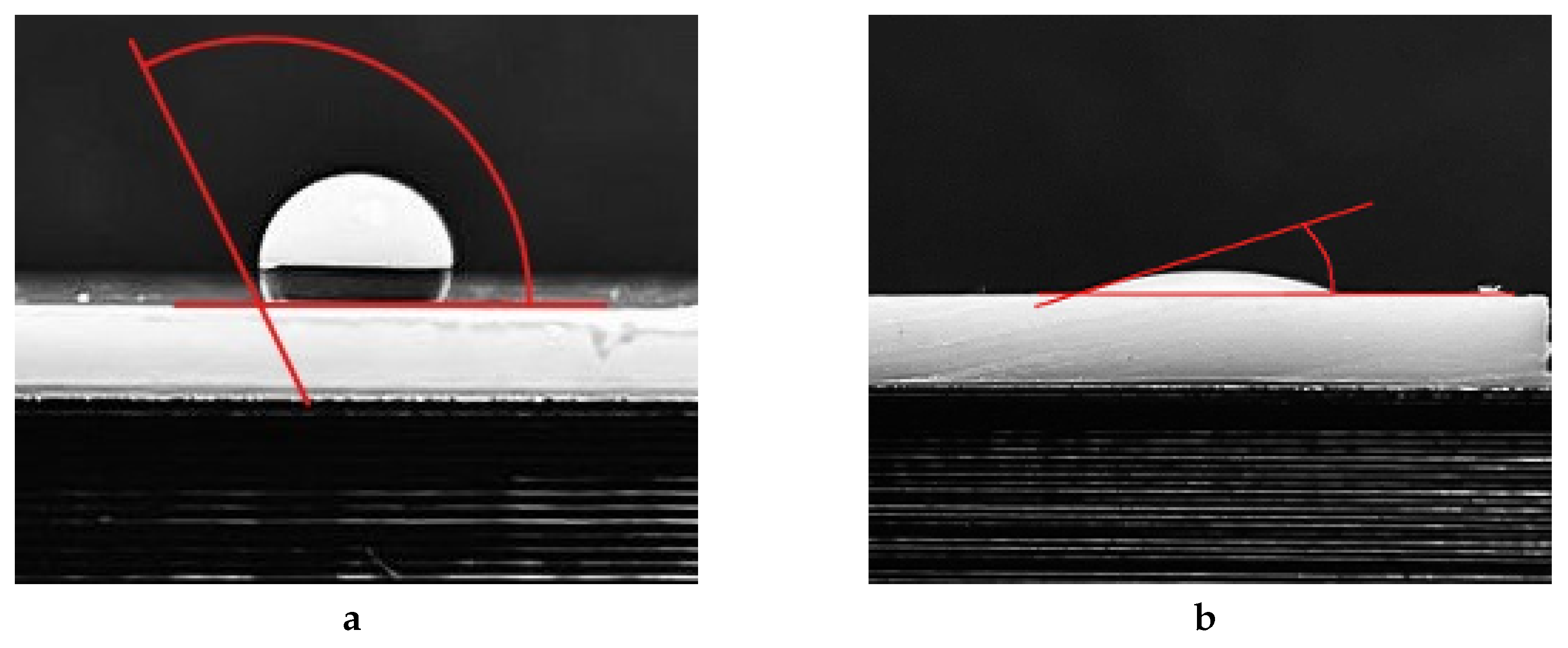
Figure 8.
Dependence of WCA on the working gas pressure.
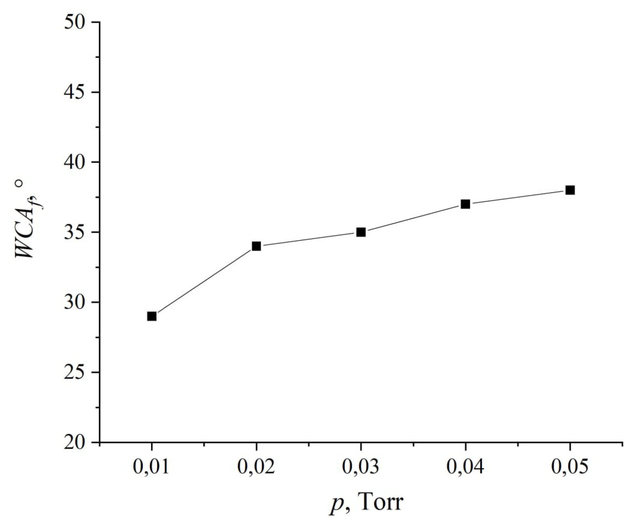
Figure 9.
Dependence of WCA on the discharge power.
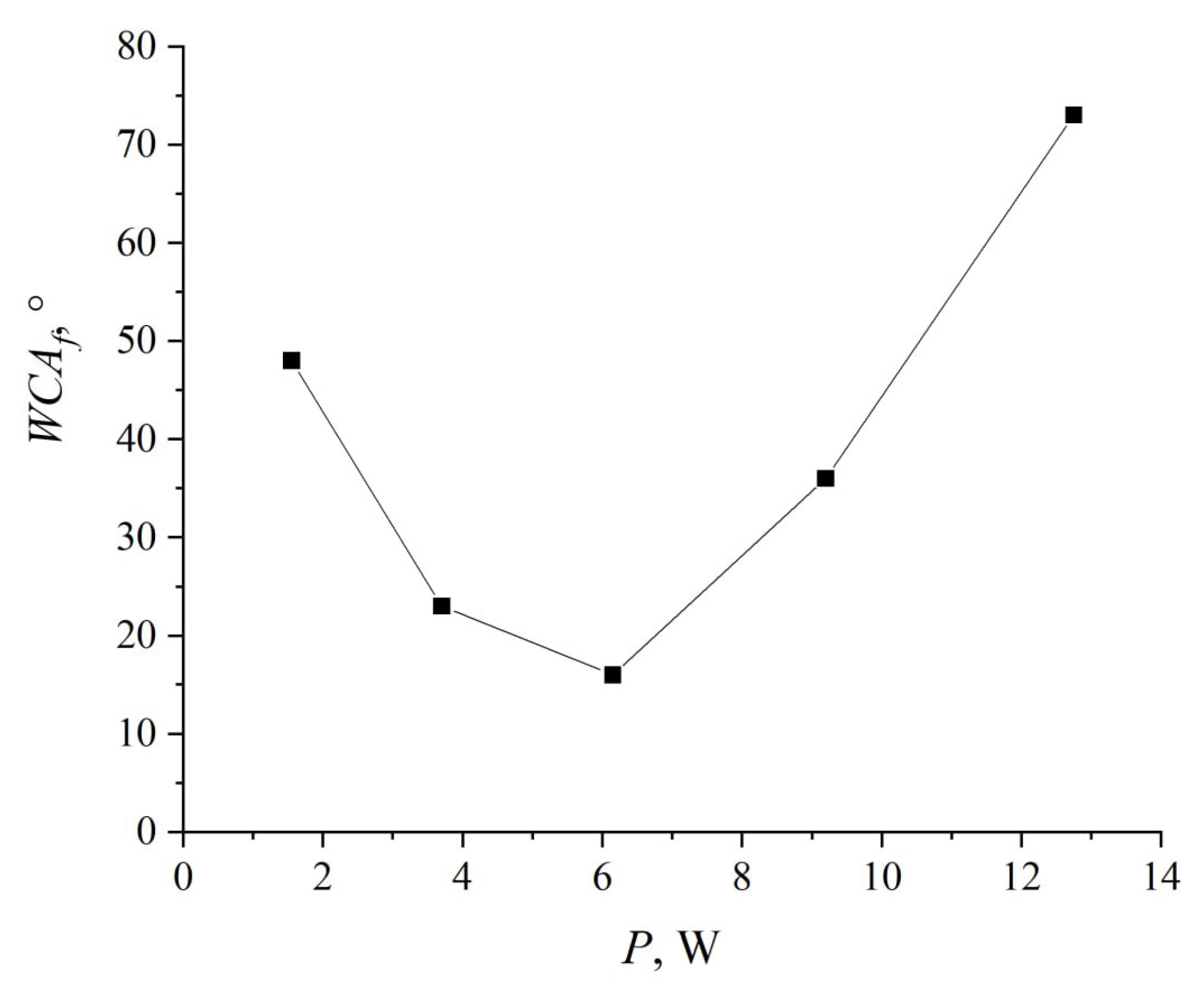
Figure 10.
Dependence of WCA on the duration of the process.

Figure 11.
Dependence of WCA on the recovery time duration.
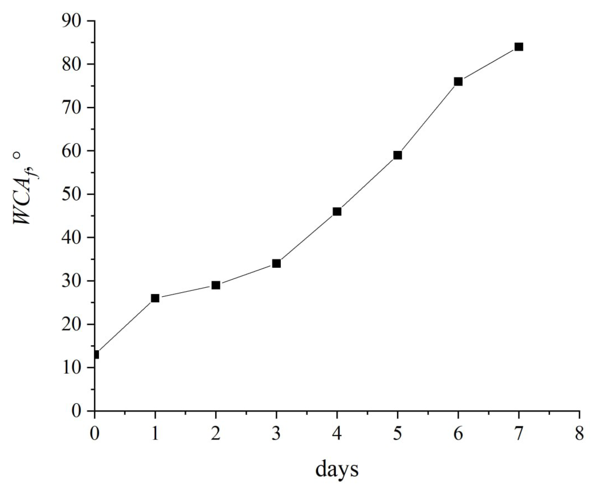
Figure 12.
Average WCA after the treatment using various gases.
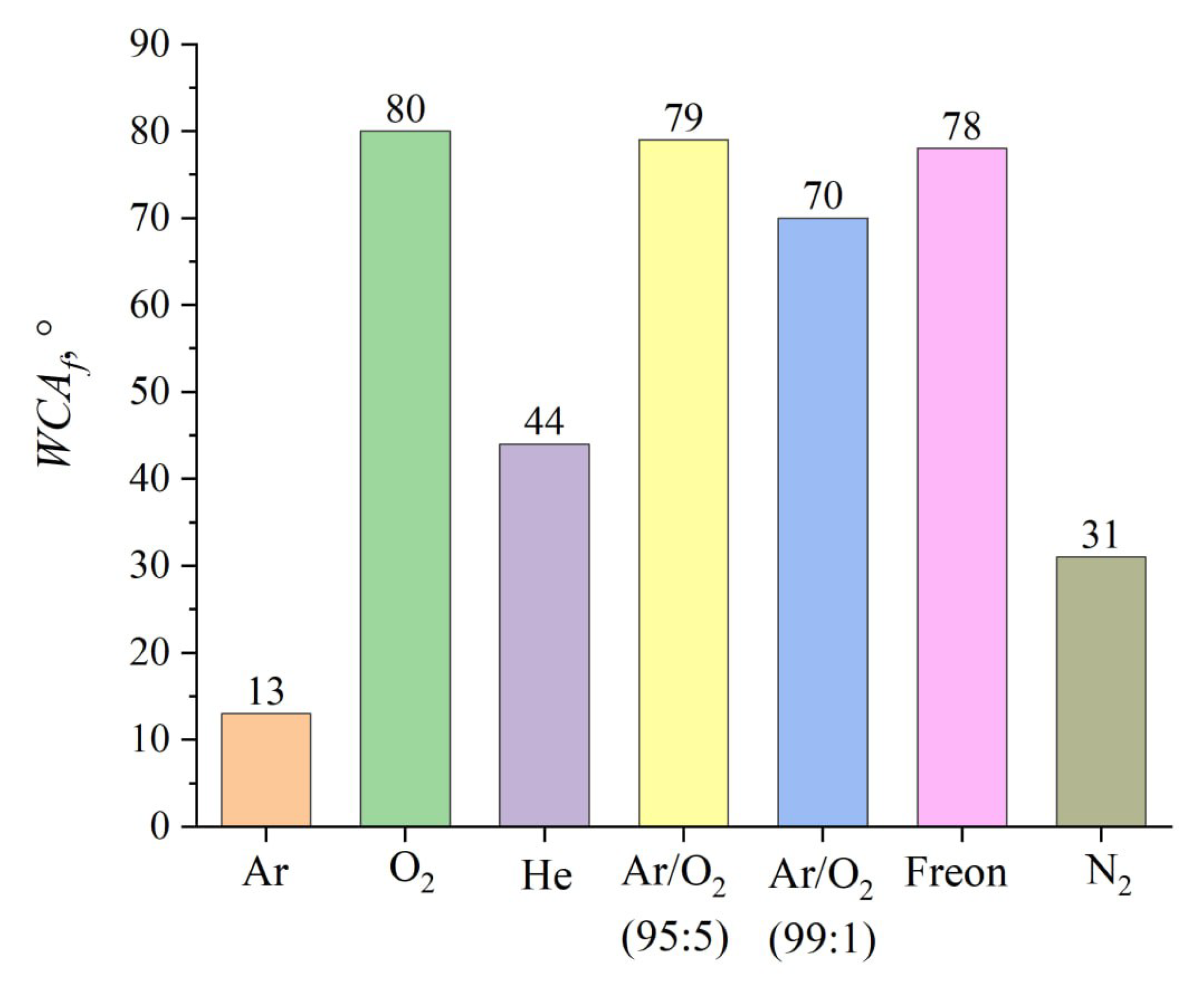
Figure 13.
Emission spectra of various gases.
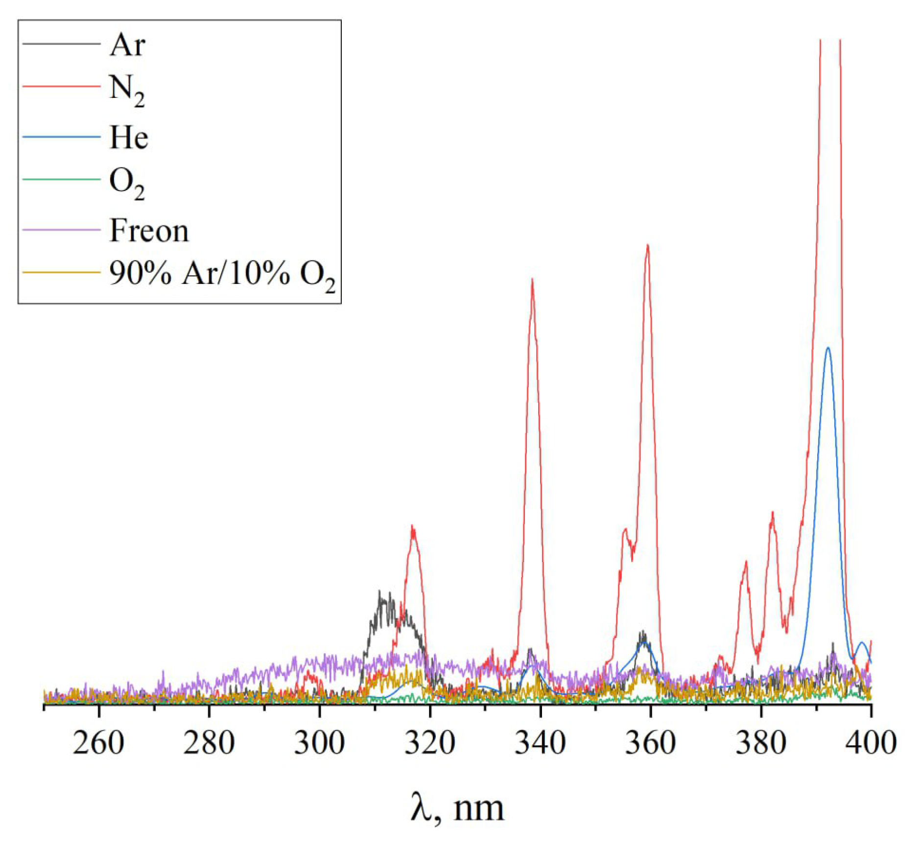
Figure 14.
Determination of surface energy of PTFE plate treated in argon glow discharge.
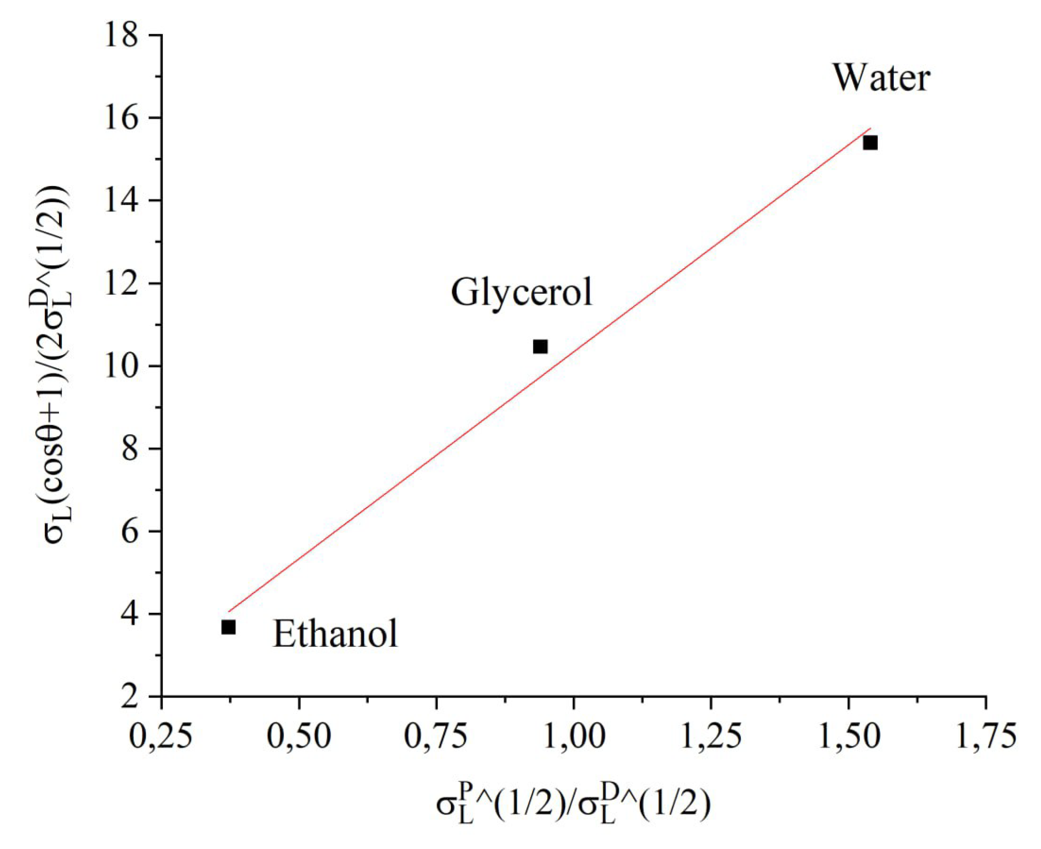
Figure 15.
Comparison of the results of measuring the WCA and calculating the surface energy value discharge.
Figure 15.
Comparison of the results of measuring the WCA and calculating the surface energy value discharge.
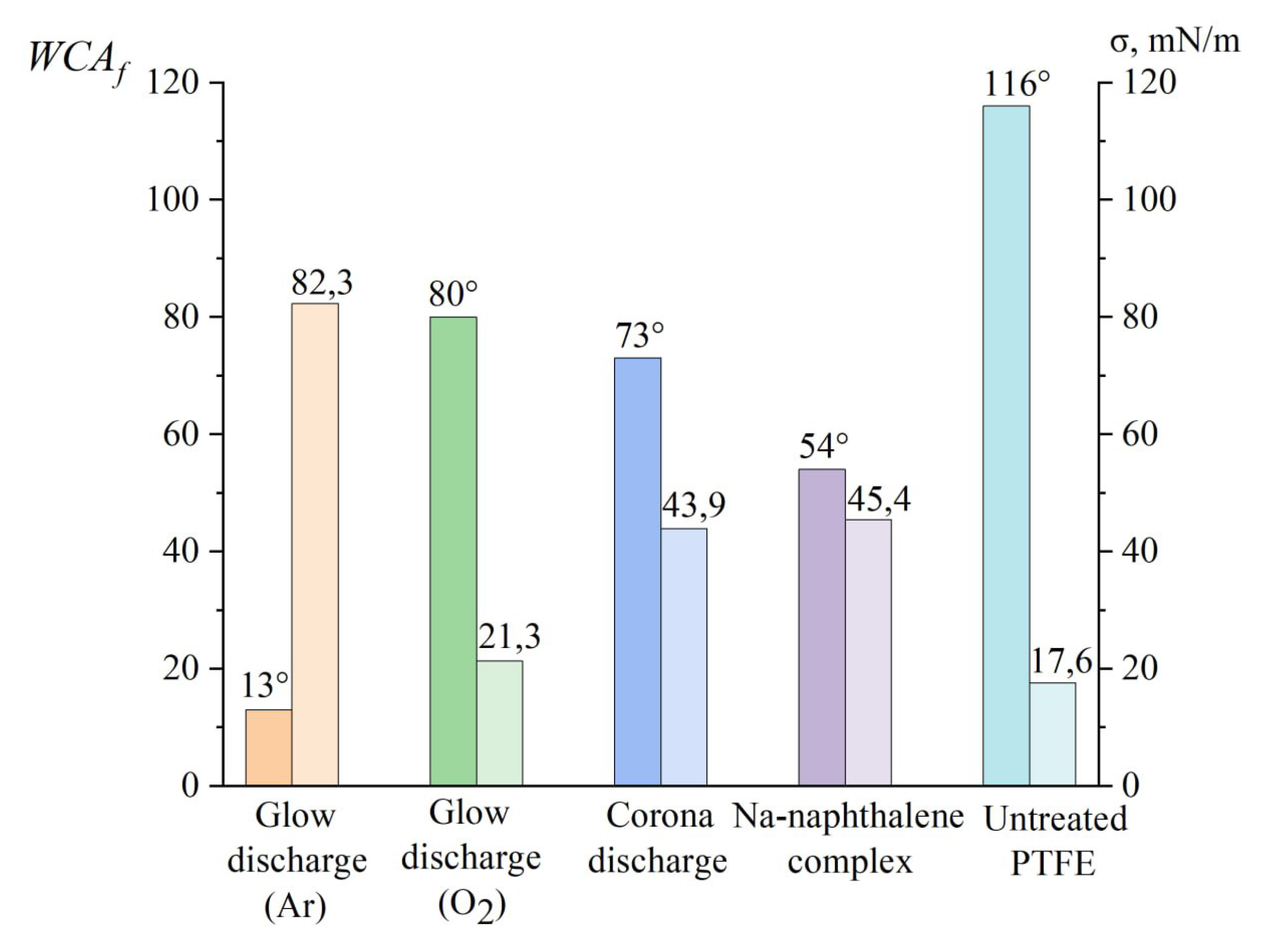

Table 1.
Discharge parameters in the stabilized discharge current mode (10 mA).
| Pressure, Torr | Voltage, V | Power, W |
|---|---|---|
| 1 | 960 | 9.6 |
| 2 | 590 | 5.9 |
| 3 | 370 | 3.7 |
| 4 | 320 | 3.2 |
| 5 | 290 | 2.9 |
Table 2.
Values of surface energy and its polar and dispersion components of the liquids used [27].
Table 2.
Values of surface energy and its polar and dispersion components of the liquids used [27].
| Liquid | , mN/m | , mN/m | , mN/m |
|---|---|---|---|
| Water | 51 | 21.8 | 72.8 |
| Glycerol | 30 | 34 | 64 |
| Ethanol | 2.6 | 18.8 | 22.4 |
Table 3.
Values of the WCAs of activated PTFE measured with various liquids.
| Treatment | WCA θ, ° | ||
| Water | Glycerol | Ethanol | |
| untreated PTFE | |||
| Ar | 116 | 145 | 9 |
| Glow discharge | |||
| Ar | 13 | 16 | 0 |
| O2 | 80 | 99 | 6 |
| He | 44 | 54 | 3 |
| 99% / 1% O2 | 79 | 97 | 6 |
| 95% / 5% O2 | 70 | 86 | 5 |
| Freon | 78 | 96 | 6 |
| N2 | 31 | 38 | 2 |
| Corona discharge | |||
| Air | 73 | 90 | 2 |
| Chemical treatment | |||
| Na-naphtalene complex | 54 | 67 | 4 |
Table 4.
Surface energies of the activated PTFE.
| Treatment | , mN/m | , mN/m | , mN/m |
|---|---|---|---|
| untreated PTFE | |||
| Ar | 0 | 17.6 | 17.6 |
| Glow discharge | |||
| Ar | 77.9 | 4.3 | 82.3 |
| O2 | 12.4 | 8.9 | 21.3 |
| He | 64.7 | 1.3 | 66.0 |
| 99% / 1% O2 | 44.4 | 0.0 | 44.4 |
| 95% / 5% O2 | 36.9 | 0.1 | 37.0 |
| Freon | 37.9 | 3.3 | 41.2 |
| N2 | 72.6 | 2.5 | 75.1 |
| Corona discharge | |||
| Air | 28.1 | 15.8 | 43.9 |
| Chemical treatment | |||
| Na-naphtalene complex | 39.3 | 6.0 | 45.4 |
Table 5.
Dielectric parameters of the PTFE measured at microwaves before and after the activation.
| treatment | ||
|---|---|---|
| untreated PTFE | 2.1 | 0.0005 |
| glow discharge | 2.1 | 0.0005 |
| chemical | 2.15 - 2.2 | 0.0006 |
Disclaimer/Publisher’s Note: The statements, opinions and data contained in all publications are solely those of the individual author(s) and contributor(s) and not of MDPI and/or the editor(s). MDPI and/or the editor(s) disclaim responsibility for any injury to people or property resulting from any ideas, methods, instructions or products referred to in the content. |
© 2025 by the authors. Licensee MDPI, Basel, Switzerland. This article is an open access article distributed under the terms and conditions of the Creative Commons Attribution (CC BY) license (http://creativecommons.org/licenses/by/4.0/).
Copyright: This open access article is published under a Creative Commons CC BY 4.0 license, which permit the free download, distribution, and reuse, provided that the author and preprint are cited in any reuse.


