
Submitted:
14 January 2025
Posted:
14 January 2025
You are already at the latest version
Abstract
The rapid advancement of artificial intelligence (AI) technologies has significantly increased the demand for high-performance computational hardware. Resistive Random-Access Memory (RRAM)-based Compute-in-Memory (CIM) technology shows great potential for addressing the data transfer bottleneck and supporting high-performance computing (HPC). In this paper, a multi-scale thermal model is developed to evaluate the temperature distribution in RRAM-based CIM chips and the influence of various factors on thermal behavior. The results indicate that hotspot temperatures can be mitigated by reducing the epoxy molding compound (EMC) thickness, increasing the substrate thickness, and lowering boundary thermal resistance. Moreover, optimizing the layout of analog computing circuits and digital circuits can reduce the maximum temperature by up to 4.04℃. Furthermore, the impact of temperature on the conductance of RRAM devices and the inference accuracy of RRAM-based CIM chips is analyzed. Simulation results reveal that thermal-induced accuracy loss in CIM chips is significant, but the computation correction method effectively reduces the accuracy loss from 66.4% to 1.4% at 85 ℃.
Keywords:
RRAM-based CIM chips
; thermal modeling
; thermal analysis
1. Introduction
AI technologies, for example autonomous driving, large language models (LLMs), and cloud computing, have garnered significant attention and widespread application in recent years [1,2,3]. However, the rapidly increasing demand for computational hardware has become a critical challenge [4]. The memory wall has emerged as a bottleneck for improving the performance of integrated circuits [5]. Significant energy and latency are consumed during frequent data transfers between physically separated memory and computing units in the conventional Von Neumann architecture [6,7]. CIM technology based on emerging non-volatile memory (eNVM) device, such as RRAM, can perform both storage and computation functions within a single device [8,9,10]. This technology demonstrates significant potential for overcoming the bottleneck of the memory wall, and has become a promising choice for AI applications including image classification, human-machine interface, and image-reconstruction [11,12,13].
RRAM-based CIM chips have developed rapidly in recent years. However, power density of CIM chips has an increasing trend and addressing thermal issues has become increasingly urgent [14]. Recent studies indicate that RRAM-based CIM chips are capable of performing matrix-vector multiplication [15,16,17,18]. During the computing process, the parallel operation of RRAM devices results in high local power consumption and high local temperatures [19]. Furthermore, Both the characteristics of RRAM devices and overall chip performance are highly temperature-sensitive [20]. For example, the conductance of analog RRAM device drifts with temperature. In particular, when analog devices are used to represent multiple bits, the conductance drift leads to significant degradation in computing accuracy of the chip. Without effective thermal management methods, the performance of CIM chips will decline significantly [21]. Some existing works primarily focus on the RRAM device characteristic, for example compact model of the temperature coefficient , retention characteristics [20,22]. However, these models fail to account for the impact of temperature distribution and neural network from a system-level perspective. Chip-level thermal simulations often treat the entire chip as a uniform heat source, disregarding the detailed circuit structure [23]. Some works have explored multi-scale thermal simulations [19], but comprehensive analyses of temperature distribution and thermal effects in CIM chips remain incomplete, lacking detailed analysis of packaging process.
In this work, a multi-scale thermal model is developed to evaluate the temperature distribution in RRAM-based CIM chips. This model is further employed to analyze the influence of boundary thermal resistance, the layout of digital circuits and analog computing module tiles, the thickness of the EMC, the thickness of the substrate. Furthermore, the impact of temperature on RRAM device conductance and the inference accuracy of RRAM-based CIM chips is investigated. Simulation results reveal that the computing accuracy loss of CIM chips due to rising temperatures is unacceptable and the computation correction method can reduce the accuracy loss from 66.4% to 1.4% at 85 ℃.
2. Thermal modeling
The thermal modeling and analysis framework for RRAM-based CIM chips is shown in Figure 1. First, a multi-scale thermal model is constructed for CIM chips with parameters extracted from a real 28nm CIM chip, and device characteristics as well as packaging factors are also considered. Second, based on Fourier's law and the finite element method (FEM), the equations are formulated and solved under steady-state conditions in this work. Third, we evaluate the temperature distribution of the CIM chips and the impact of various factors on temperature, including process, circuit architecture, and cooling methods. Fourth, the thermal effects on RRAM devices and CIM chips will be evaluated. The conductance range of RRAM devices in this work is from 2 to 20 μS. Within this range, the conductance of the RRAM devices exhibits semiconductor behavior with a positive temperature coefficient. A compact model of RRAM conductance is used to evaluate the impact of temperature on the conductance of the RRAM devices. Next, a typical deep neural network, the 18-layer ResNet neural network (ResNet-18) [24] is used to classify images from the CIFAR-10 [25] dataset to evaluate the thermal effect on computing accuracy of RRAM-based CIM chips. Finally, based on the simulation results, several design guidelines for optimizing the temperature distribution and thermal-induced performance degradation are provided.
The architecture of the RRAM-based CIM chip from RRAM device to the full CIM chip used in the modeling is shown in Figure 2. RRAM device can change its state through ion movement and process analog signals. The RRAM used is the TiN/HfOx/TaOy/TiN memristor in one-transistor-one-resistor (1T1R) cell structure. Based on Ohm's law and Kirchhoff's law, the RRAM array performs matrix-vector multiplication. One RRAM array and the corresponding peripheral circuits, such as analog-digital converters (ADCs) and digital-analog converters (DACs), form one processing element (PE). Each tile consists of 4 PEs and the corresponding peripheral circuits, such as the tile controller, shift and adder, activation function, and pooling modules. Nine tiles and their corresponding peripheral circuits constitute the RRAM-based CIM chip. The convolutional parameters of ResNet-18 are mapped onto the RRAM arrays, while certain specialized computations, such as pooling, are handled by the digital circuit section.
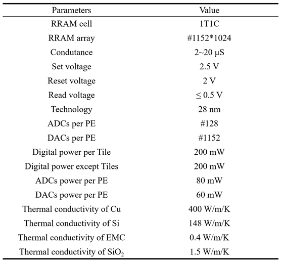
The parameters used in this work are listed in Table 1. The conductance range of RRAM is between 2 and 20 μS, and each RRAM device has 16 independent conductance states.
The flip-chip packaging method is adopted for the CIM chip in this work. Joule heat is primarily released into the environment from the upper surface. The heat dissipation from the four sides and the bottom side is minimal, with their thermal resistances approximated as adiabatic. The ambient temperature is assumed to be 26.85 °C.
3. Results of thermal effect evaluation
Based on the multi-scale thermal model, the temperature distribution of the RRAM-based CIM chip is obtained. The temperature map of the CIM chip is shown in Figure 3a, when power of each RRAM array is 40mW with the upper thermal resistance of 7 cm²·K/W. As illustrated in the figure, there are hotspots in the PE areas with higher power density, while the temperature in the digital circuit areas remains relatively low. The temperature difference across the chip reaches approximately 10 ℃. The impact of boundary thermal resistance on the temperature distribution of CIM chips is evaluated. As Figure 3b shows, with the increase of boundary thermal resistance, both the average temperature and maximum temperature of the CIM chip increase and the temperature difference also increases significantly. Furthermore, Furthermore, the difference between the maximum and average temperatures grows as the boundary thermal resistance increases. Therefore, reducing boundary thermal resistance can effectively lower the chip's hotspot temperature.. If the temperature limit is set to 85 °C, the boundary thermal resistance should not exceed 6.8 cm²K/W to ensure the safe operation of the chip.
The thermal conductivity of the EMC material is low, so the thickness of the EMC layer significantly impacts the maximum temperature of the chip. As shown in Figure 4a, the maximum temperature differs by 6.8 °C between a 50 μm thick EMC cap and no EMC layer. The substrate material of the chip is monocrystalline silicon, which has a high thermal conductivity of 148 W/m/K. Figure 4b evaluates the impact of substrate thickness on both the maximum and average temperatures in the chip. As shown in the figure, when the substrate thickness is less than 300 μm, the hotspot temperature decreases rapidly as the substrate thickness increases. However, when the substrate thickness exceeds 300 μm, the temperature reduction effect becomes less significant as the thickness increases further. As the substrate thickness increases, the average temperature of the chip shows a slow increasing trend.
To reduce the hotspot temperature, chip design optimization can be applied. As shown in Figure 3a, the temperatures in the digital circuit area are lower than that in the tile area with high power. By adjusting the position of the tiles and placing the digital circuits around the tiles, the distribution of temperature can be improved. The optimized result, shown in Figure 5a, indicates a more uniform temperature distribution. The temperature difference between the maximum and minimum temperatures on the chip is only about 2°C. Compared with the original configuration shown in Figure 5b, the maximum temperature has decreased by 4.04 °C after optimization.
Based on the above evaluations, hotspot temperatures on the chip can be reduced by optimizing the layout of tiles and digital circuits, decreasing the EMC thickness, appropriately increasing the substrate thickness, and reducing boundary thermal resistance. Additionally, reducing the power consumption of various on-chip modules can further help lower the temperature.
The drift of RRAM conductance with temperature is a basic characteristic of semiconductor materials. The conductance of RRAM device drifts when temperatures increase. The 4-bit analog RRAM devices are used in the simulation, and the conductance difference between two adjacent states is only about 1 μS. As shown in Figure 6a, the conductance of RRAM device drift with temperature based on the compact model of RRAM conductance [19]. The conductance drift significantly exceeds the difference between two states, resulting in data drift of the CIM. As a result, the mapped weight of DNN on CIM chips will drift when temperature increases, which leads to accuracy loss of the CIM chip. The computing accuracy loss of the CIM chip is shown in Figure 6a, where the accuracy loss is found to be significant and unacceptable. And as the temperature increases, the accuracy decreases more. Optimizing the temperature coefficient of RRAM materials can reduce conductivity drift and computing accuracy loss of CIM chips. For the current RRAM devices, we explore optimization from the circuit design level. The temperatures within a single RRAM array are almost uniform, leading to a similar drift ration of RRAM conductance. The ADC quantization process must be scaled to correct the conductance change with temperature. According to the simulation results in Figure 6b, ADC correction can decrease the accuracy loss from 66.4% to 1.4% at 85 ℃.
4. Conclusions
A multi-scale thermal simulation model for RRAM-based CIM chips is developed in this paper. Then the temperature distribution characteristics of CIM chips and the impact of boundary thermal resistance are evaluated. 4.04 ℃ has been reduced by optimizing the layout of digital circuits and tiles. Finally, the effect of temperature on RRAM conductance and CIM computing accuracy is analyzed, and optimized solutions are proposed. Based on the evaluation results, the ADC correction method is shown to reduce the accuracy loss from 66.4% to 1.4% at 85 ℃.
Author Contributions
Conceptualization, H.W.; methodology, A.M., B.G. and P.Y.; software, A.M.; validation, A.M., H.Q. and J.T.; writing—original draft preparation, A.M.; writing—review and editing, B.G.. All authors have read and agreed to the published version of the manuscript. All authors have read and agreed to the published version of the manuscript.
Funding
This research received no external funding.
Institutional Review Board Statement
Not applicable.
Informed Consent Statement
Not applicable.
Data Availability Statement
The original contributions presented in this study are included in the article. Further inquiries can be directed to the corresponding authors.
Acknowledgments
This work is supported in part by the MOST of China (2021ZD0201200), the NSFC (62374019, 62025111, 92064015).
Conflicts of Interest
The authors declare no conflicts of interest.
References
- Feng, S.; Yan, X.; Sun, H.; Feng, Y.; Liu, H.X. Intelligent driving intelligence test for autonomous vehicles with naturalistic and adversarial environment. Nature communications 2021, 12, 748. [Google Scholar] [CrossRef] [PubMed]
- Chang, Y.; et al. A survey on evaluation of large language models. ACM Transactions on Intelligent Systems and Technology 2024, 15, 1–45. [Google Scholar] [CrossRef]
- Sandhu, A.K. Big data with cloud computing: Discussions and challenges. Big Data Mining and Analytics 2021, 5, 32–40. [Google Scholar] [CrossRef]
- Strubell, E.; Ganesh, A.; McCallum, A. Energy and policy considerations for modern deep learning research. In Proceedings of the AAAI conference on artificial intelligence; 2020; Volume 34. [Google Scholar] [CrossRef]
- Haensch, W.; et al. Compute in-memory with non-volatile elements for neural networks: A review from a co-design perspective. Advanced Materials 2023, 35, 2204944. [Google Scholar] [CrossRef] [PubMed]
- Horowitz, M. 1.1 computing's energy problem (and what we can do about it). In Proceedings of the 2014 IEEE international solid-state circuits conference digest of technical papers (ISSCC); 2014. [Google Scholar] [CrossRef]
- Wong, H.-S.P.; Salahuddin, S. Memory leads the way to better computing. Nature nanotechnology 2015, 10, 191–194. [Google Scholar] [CrossRef] [PubMed]
- Ielmini, D.; Wong, H.-S.P. In-memory computing with resistive switching devices. Nature electronics 2018, 1, 333–343. [Google Scholar] [CrossRef]
- Zidan, M.A.; Strachan, J.P.; Lu, W.D. The future of electronics based on memristive systems. Nature electronics 2018, 1, 22–29. [Google Scholar] [CrossRef]
- Lanza, M.; et al. Memristive technologies for data storage, computation, encryption, and radio-frequency communication. Science 2022, 376, eabj9979. [Google Scholar] [CrossRef] [PubMed]
- Wan, W.; Kubendran, R.; Schaefer, C.; Eryilmaz, S.B.; Zhang, W.; Wu, D.; Deiss, S.; Raina, P.; Qian, H.; Gao, B.; et al. A compute-in-memory chip based on resistive random-access memory. Nature 2022, 608, 504–512. [Google Scholar] [CrossRef]
- Feng, Y.; Zhang, Y.; Zhou, Z.; Huang, P.; Liu, L.; Liu, X.; Kang, J. Memristor-based storage system with convolutional autoencoder-based image compression network. Nature Communications 2024, 15, 1132. [Google Scholar] [CrossRef]
- Yuan, R.; Tiw, P.J.; Cai, L.; Yang, Z.; Liu, C.; Zhang, T.; Ge, C.; Huang, R.; Yang, Y. A neuromorphic physiological signal processing system based on VO2 memristor for next-generation human-machine interface. Nature Communications 2023, 14, 3695. [Google Scholar] [CrossRef] [PubMed]
- Kaul, A.; Luo, Y.; Peng, X.; Yu, S.; Bakir, M.S. Thermal reliability considerations of resistive synaptic devices for 3D CIM system performance. In Proceedings of the 2021 IEEE International 3D Systems Integration Conference (3DIC); 2021. [Google Scholar] [CrossRef]
- Chen, W.-H.; Dou, C.; Li, K.-X.; Lin, W.-Y.; Li, P.-Y.; Huang, J.-H.; Wang, J.-H.; Wei, W.-C.; Xue, C.-X.; Chiu, Y.-C.; et al. CMOS-integrated memristive non-volatile computing-in-memory for AI edge processors. Nature Electronics 2019, 2, 420–428. [Google Scholar] [CrossRef]
- Hung, J.-M.; Xue, C.-X.; Kao, H.-Y.; Huang, Y.-H.; Chang, F.-C.; Huang, S.-P.; Liu, T.-W.; Jhang, C.-J.; Su, C.-I.; Khwa, W.-S.; et al. A four-megabit compute-in-memory macro with eight-bit precision based on CMOS and resistive random-access memory for AI edge devices. Nature Electronics 2021, 4, 921–930. [Google Scholar] [CrossRef]
- Xue, C.-X.; et al. 24.1 A 1Mb multibit ReRAM computing-in-memory macro with 14.6 ns parallel MAC computing time for CNN based AI edge processors. In Proceedings of the 2019 IEEE International Solid-State Circuits Conference-(ISSCC); 2019. [Google Scholar] [CrossRef]
- Xue, C.-X.; Chiu, Y.-C.; Liu, T.-W.; Huang, T.-Y.; Liu, J.-S.; Chang, T.-W.; Kao, H.-Y.; Wang, J.-H.; Wei, S.-Y.; Lee, C.-Y.; et al. A CMOS-integrated compute-in-memory macro based on resistive random-access memory for AI edge devices. Nature Electronics 2021, 4, 81–90. [Google Scholar] [CrossRef]
- Ma, A.; Gao, B.; Liu, Y.; Yao, P.; Liu, Z.; Du, Y.; Li, X.; Xu, F.; Hao, Z.; Tang, J.; et al. Multi-scale thermal modeling of RRAM-based 3D monolithic-integrated computing-in-memory chips. In Proceedings of the 2022 International Electron Devices Meeting (IEDM); 2022. [Google Scholar] [CrossRef]
- Xu, M.; Gao, B.; Xu, F.; Wu, W.; Tang, J.; Chen, J.; Qian, H. A Compact Model of Analog RRAM Considering Temperature Coefficient for Neural Network Evaluation. In Proceedings of the 2021 5th IEEE Electron Devices Technology & Manufacturing Conference (EDTM); 2021. [Google Scholar] [CrossRef]
- Ma, A.; Gao, B.; Mou, X.; Yao, P.; Du, Y.; Tang, J.; Qian, H.; Wu, H. Thermal Induced Retention Degradation of RRAM-based Neuromorphic Computing Chips. In Proceedings of the 2023 IEEE International Reliability Physics Symposium (IRPS); 2023; pp. 1–6. [Google Scholar] [CrossRef]
- Shim, W.; Meng, J.; Peng, X.; Seo, J.-S.; Yu, S. Impact of multilevel retention characteristics on RRAM based DNN inference engine. In Proceedings of the 2021 IEEE International Reliability Physics Symposium (IRPS); 2021; pp. 1–4. [Google Scholar] [CrossRef]
- Kaul, A.; Peng, X.; Rajan, S.K.; Yu, S.; Bakir, M.S. Thermal modeling of 3D polylithic integration and implications on BEOL RRAM performance. In Proceedings of the 2020 IEEE International Electron Devices Meeting (IEDM); 2020; p. 13. [Google Scholar] [CrossRef]
- He, K.; et al. Deep residual learning for image recognition. In Proceedings of the IEEE conference on computer vision and pattern recognition; 2016. [Google Scholar]
- Krizhevsky, A.; Hinton, G. Learning multiple layers of features from tiny images. 2009: 7.
Figure 1.
The thermal modeling and analysis framework of RRAM-based CIM chips.
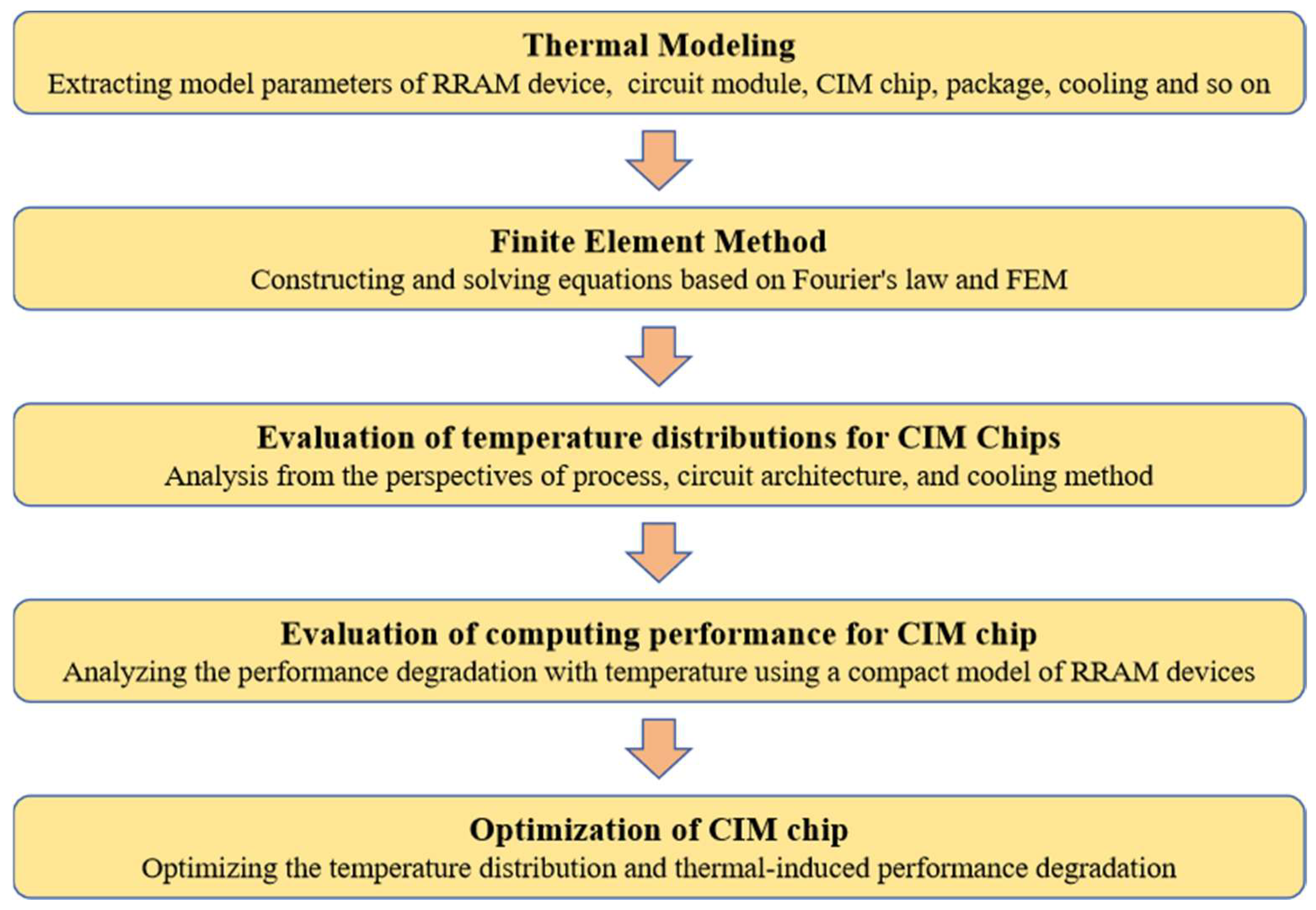
Figure 2.
The architecture of CIM chip used in modeling.
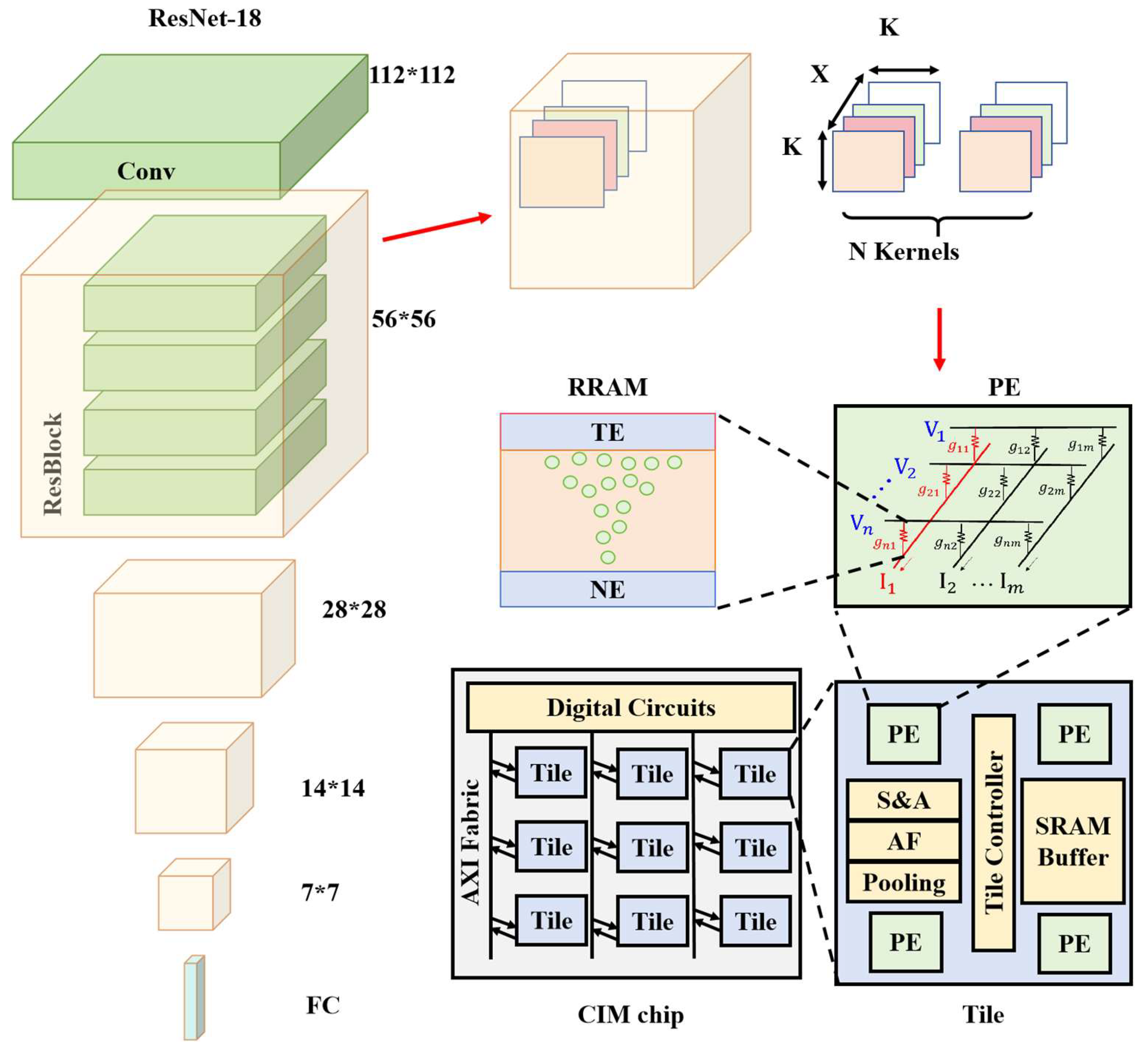
Figure 3.
(a)Temperature distribution of CIM chips with the bottom thermal resistance of 7cm²K/W. (b) Evaluation of the influence of the boundary thermal resistance on temperature.
Figure 3.
(a)Temperature distribution of CIM chips with the bottom thermal resistance of 7cm²K/W. (b) Evaluation of the influence of the boundary thermal resistance on temperature.
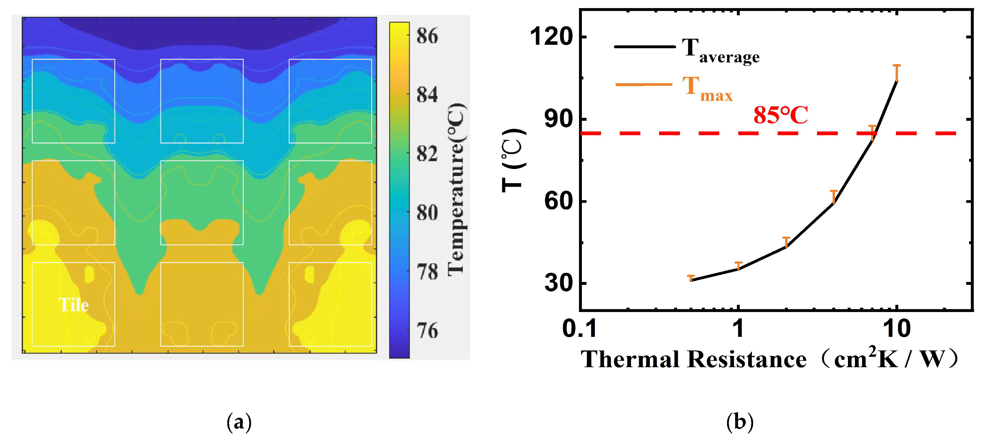
Figure 4.
(a) Evaluation of the influence of the EMC thickness on temperature. (b) Evaluation of the influence of the chip substrate thickness on temperature.
Figure 4.
(a) Evaluation of the influence of the EMC thickness on temperature. (b) Evaluation of the influence of the chip substrate thickness on temperature.
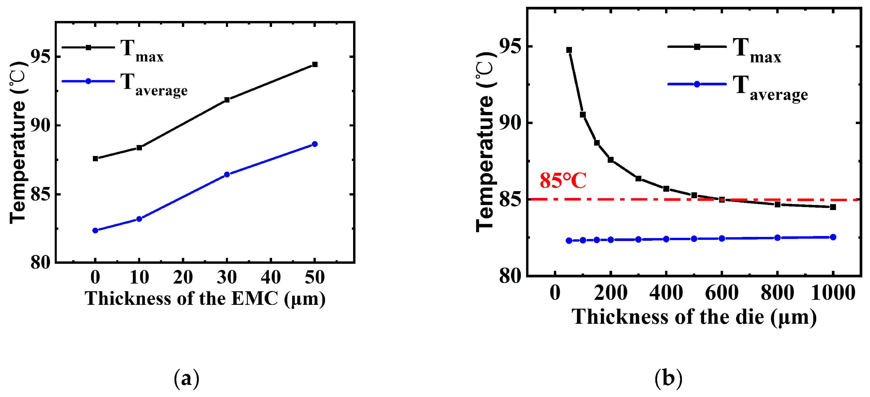
Figure 5.
(a) Temperature distribution after optimizing. (b) Comparison of the maximum and average temperatures before and after optimization.
Figure 5.
(a) Temperature distribution after optimizing. (b) Comparison of the maximum and average temperatures before and after optimization.
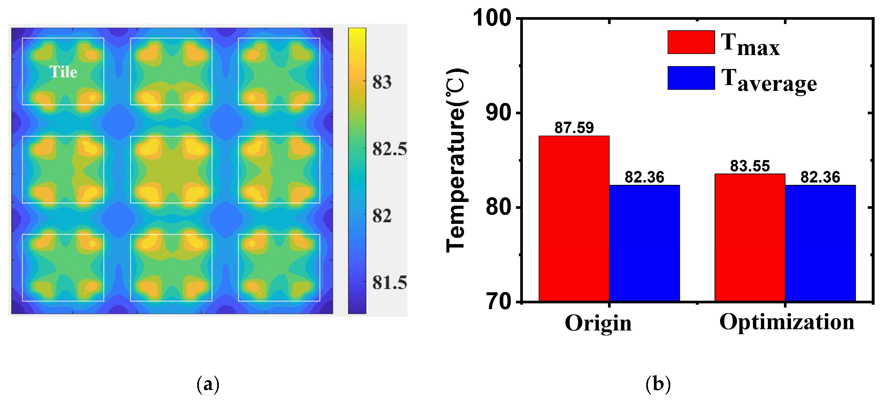
Figure 6.
Evaluation of thermal effect on RRAM device and CIM chips. (a) The conductance of RRAM drift with temperature. (b) Thermal induced accuracy loss and optimization with ADC correction method.
Figure 6.
Evaluation of thermal effect on RRAM device and CIM chips. (a) The conductance of RRAM drift with temperature. (b) Thermal induced accuracy loss and optimization with ADC correction method.
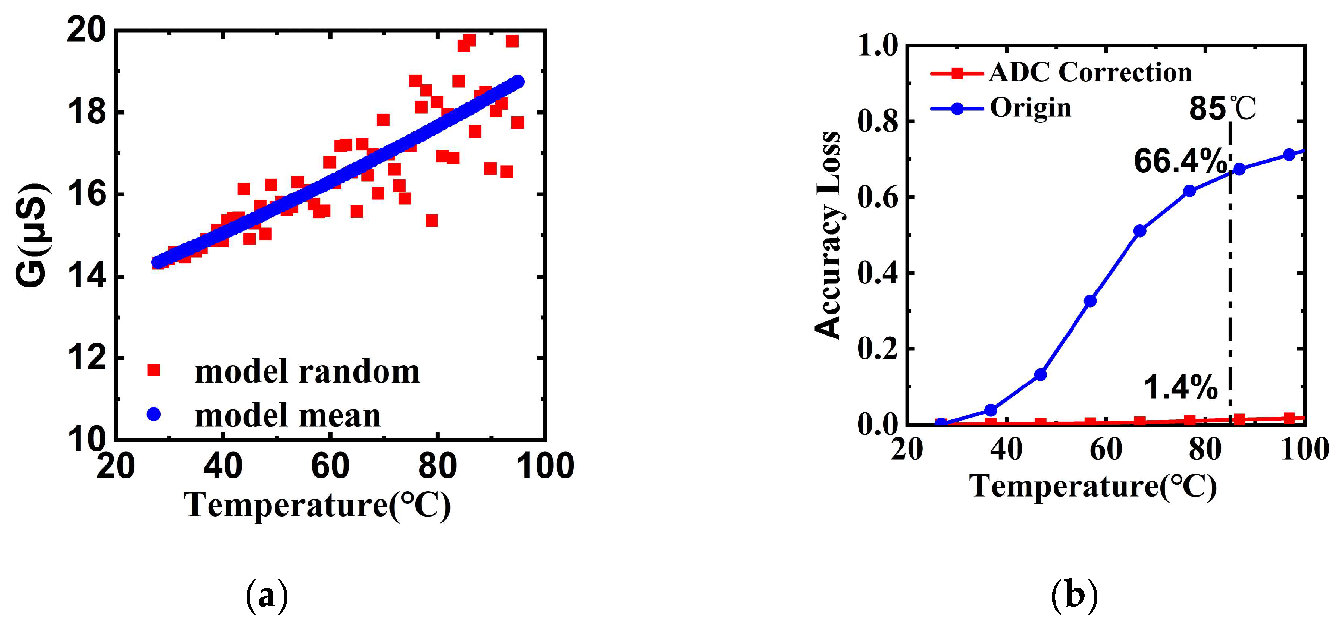

Table 1.
Parameters used in this work.
 |
Disclaimer/Publisher’s Note: The statements, opinions and data contained in all publications are solely those of the individual author(s) and contributor(s) and not of MDPI and/or the editor(s). MDPI and/or the editor(s) disclaim responsibility for any injury to people or property resulting from any ideas, methods, instructions or products referred to in the content. |
© 2025 by the authors. Licensee MDPI, Basel, Switzerland. This article is an open access article distributed under the terms and conditions of the Creative Commons Attribution (CC BY) license (http://creativecommons.org/licenses/by/4.0/).
Copyright: This open access article is published under a Creative Commons CC BY 4.0 license, which permit the free download, distribution, and reuse, provided that the author and preprint are cited in any reuse.


