
Submitted:
11 January 2025
Posted:
14 January 2025
You are already at the latest version
Abstract
The removal of 3D-printed parts from build platforms in Stereolithographic (SLA) printing poses significant challenges due to the strong adhesion of parts to the build platform. A device was designed that employs a guided sliding blade mechanism, effectively utilizing the wedge effect for safe and efficient detachment. This method minimizes damage to both the printed parts and the build platform, enhancing the efficiency and safety of the post-printing process. The efficacy of the design was demonstrated with multiple 3D-printed parts of different materials and sizes.
Keywords:
3D printing
; additive manufacturing
; part removal
; build platform
; mechanism
; product design
; SLA
1. Introduction
Additive manufacturing (AM) technologies have rapidly advanced in recent years, enabling the production of a wide array of products with minimal material costs and in a short time frame, all on a single machine called as 3D printer ([1]). Initially used primarily for rapid prototyping, 3D printing has now expanded into one-off and small-scale production ([2,3]). A 3D printer functions as an automatic device, transforming a computer model of an object into its material form.
Since early 2010, resin 3D printing, also known as stereolithographic (SLA) 3D printing or vat-polymerization printing, has emerged as a promising technique ([4]). This technique involves curing photopolymerizable resins with a UV or visible light source in sequential layers. Stereolithographic apparatus (SLA) printers use a UV laser guided by mirrors to cure resin point-by-point, while Direct Light Processing (DLP) printers use UV projectors to cure entire layers simultaneously, offering slightly better resolution ([5]).
Stereolithography (SLA)-based 3D printing has significantly transformed manufacturing, offering high precision and the capability to create complex parts across various sectors such as automotive, aerospace, and healthcare due to its cost-effectiveness, reduced fabrication time, and enhanced product customization ([6,7,8]). Despite these advantages, a major challenge persists in the post-printing process: the removal of printed parts from the build platform ([9]). Traditionally, this process requires manual tools like spatulas and pliers, which demand considerable force and risk damaging both the parts and the expensive build platform. Such damage can introduce micro and macro dents, affecting subsequent print jobs and potentially leading to build failures ([10]).
Various 3D printing technologies have explored different solutions for part removal. For example, chemical-based methods and reusable powder beds are employed in some systems ([11]). Fused Deposition Modeling (FDM) often uses a thin, flexible build plate that can be manually flexed to detach printed parts. However, SLA’s need for precision necessitates a stiffer build platform. Some SLA systems incorporate thin plates atop rigid platforms, but this approach is costly and results in resin wastage and messy cleaning. Moreover, the flexing method is unsuitable for small or thin parts, being more effective for larger models with rigid materials.
Current part removal methods largely rely on manual labour, which not only limits productivity but also introduces the potential for human error. Although robotic manipulators can be used for this task, they are often redundant, complex, and expensive ([12]). Various methods have been proposed in literature and patents for removing printed products from the working surface of a 3D printer, including devices with conveyor belts, rollers, ejector pins, and compressed air supply ([12,13,15]). For models that are difficult to detach, carefully applying hot water along the build plate at the contact points can help loosen the adhesion, facilitating easier removal. However, this method is not suitable for parts made of soft printed materials or delicate geometries. Additionally, applying hot water before curing can damage the printed part ([14]). However, all these existing solutions have yet to fully address the issue.
Despite these advancements, manual handling is the most sought-after method for removing finished parts ([15]). However, the strong adhesion between the printed product and the build platform means that a simple grip with minimal force is insufficient for removal, while excessive force risks damaging the product. This limitation prevents the full automation of production processes on 3D printers, particularly for parts made from a single material ([15]). Therefore, despite the automation in the printing process, human intervention is still required to remove the printed product from the printer chamber once printing is complete. This limitation is particularly pronounced in SLA printing, where each print job must be completed on a build plate, and subsequent jobs can only begin after the previous parts are manually removed ([18]). Therefore, in the context of SLA printing, the removal of parts before commencing the next print remains a bottleneck, wasting time and resources, especially when erroneous prints are not stopped promptly. automating the process of removal of 3D printed products in existing 3D printers.
This research work focuses on developing an automated solution for this process, which is essential for enhancing productivity and fully realizing the potential of 3D printing in both small-scale and mass-production scenarios. The proposed design offers a method for safely and efficiently removing parts from the build platforms of diverse general-purpose machines. This method ensures a controlled removal process, which drastically reduces the risk of damage and the use of excessive support material. The design’s key feature is its ability to uniformly and consistently apply force to detach parts, mitigating the high-impact and uncontrolled prying associated with conventional methods. This approach not only preserves the integrity of the parts and platforms but also enhances user safety by minimizing the need for manual intervention and reducing the potential for accidents. In the context of this paper, the phrase ’part removal’ refers to the removal of all the printed materials on the build platform.
2. Analysis of Common Part Removal Methods in SLA printing
In this section, we examine the prevalent techniques used for removing 3D-printed parts from build platforms in SLA printing. We will discuss both manual and integrated removal methods, highlighting their mechanics, advantages, and limitations.
2.1. Manual Removal Technique
The above-mentioned conventional method for removing 3D printed parts from the build platform in SLA 3D printing is labour-intensive due to the strong adhesion between the resin and the platform. In such cases, users typically use a spatula provided by the SLA 3D printers ([16]). While some printers include a steel spatula, its use is discouraged due to the risk of scratching the build plate. A plastic spatula is recommended for safer removal; however, it is often ineffective because the adhesion force exceeds the plastic’s strength ([17]). Typically, users apply significant force at the junction between the part and the platform using tools like spatulas to initiate crack propagation at the adhesion interface, as illustrated in Figure 1. For safety, these spatulas are not sharp, necessitating repeated hits to achieve the desired effect. Striking the right balance of force is challenging, often requiring multiple attempts with varying impact degrees. This uncontrolled prying causes considerable wear and tear on the build platform and can lead to part failure, making successful part removal largely dependent on the chance of precise hits among numerous attempts.
2.2. Integrated Removal Techniques
In certain SLA 3D printers, such as those produced by Formlabs, an integrated removal technique is employed using a build platform equipped with a flexible steel plate. Once the printing process is complete, the steel plate can be flexed manually or automatically, as shown in Figure 2. This flexing induces a parabolic bending curvature, which effectively separates the printed part from the platform by breaking the adhesion at the contact points. The mechanics behind this method rely on the inherent elasticity of the steel plate, which, when flexed, creates a differential stress distribution. This stress concentration at the interface between the part and the build platform initiates crack propagation, leading to the detachment of the part.
However, this technique is only effective under specific conditions. It works well for large parts made from rigid materials, where the size and stiffness of the part can withstand the bending forces without deforming. For slender geometries, flexible materials, or parts with less rigidity, this method proves unsuitable. The parabolic bending curvature may not generate sufficient stress to overcome the adhesion forces, and the part may bend or deform along with the flexible steel plate rather than detach from it. Consequently, this technique has limited applicability, particularly for parts with intricate geometries or those made from softer materials, highlighting the need for more versatile and robust part removal methods in SLA 3D printing.
3. Mechanics of Part Removal Methods
Figure 3 describes the setup made in a slicing software for SLA 3D printing where the part is attached to slender cylindrical support structures, which are, in turn, attached to a raft. The raft and support structures are both considered expendable. The raft is adhered to the build platform through a significant surface area of contact, resulting in a large adhesion force. It is required to detach the raft without damaging the printed part and the expensive build platform.
Various methods can be considered for the safe and effective removal of 3D printed parts from the build platform, along with their support structures and raft, without causing damage to the platform. Here, we discuss different approaches to applying forces for part removal while analyzing their feasibility and limitations.
Case A: Application of Pull Force on the Part
One potential method involves applying a force on the part perpendicular to the build platform to pull it off (Figure 4-A). However, the weakest links are often the touch points (p), which may detach the part while leaving the support structures and raft on the build platform. The force can also damage the part itself in its weaker sections.
Case B: Application of Tangential Force on the Part
Another method involves applying a force tangentially to the build platform to remove the part (Figure 4-B). The force causes the weak support structures to break(), leaving the part detached, but the broken support structures and raft still adhere to the build platform.
Case C: Application of Pull Force on the Raft
In this context, the small size of the raft (Figure 4-C) limits the ability to effectively apply the necessary pull force, thereby complicating the removal process. Additionally, as the contact area increases, the required force correspondingly escalates. This results in compressive failure at the point of application, leading to local fragmentation rather than a shearing failure of the entire raft.
Case D: Application of Tangential Force on the Raft
The thin nature of the raft results in localized stress at the point of force application (Figure 4-D), causing the tip of the raft to break (r) while leaving the remainder of the raft intact on the build platform. The adhesive bond, combined with the total contact area, necessitates a high force requirement, particularly when the contact area is substantial. This leads to compressive failure at the point of application, resulting in local fragmentation rather than a shearing failure of the entire raft, which would require significantly higher force.
Case E: Optimal Method Using a Wedge to Induce Localized Stress
An alternate approach involves inducing localized stress at the junction between the raft and the build platform (Figure 5). This method targets the interface between the raft and the build platform where the lower region of the raft and the top region of the build platform get affected. By inserting the wedge into this interface, separation of the raft and support structures from the build platform is achieved through a series of stages without damaging the part or the platform.
The mechanics behind this removal process involve a series of failures:
- -
- Localized Compression Failure: When a wedge with wedge angle is pressed at the junction between the raft and the build platform at an angle, a localized compression failure occurs. This failure plastically deforms the material of the raft at the junction, allowing the wedge to insert itself between the raft and the build platform (Figure 5). The sub-figure in Figure 5 illustrates that a larger wedge angle increases the contact area (j), causing the raft to chip off rather than compress at the junction, thereby indicating that a lower wedge angle is preferable to initiate compression failure at the junction (i).
- -
-
Tearing Failure: Continued force induces a wedge effect, which in turn creates a bending moment that initiates a tearing failure (Figure 5). This is analogous to tearing a piece of cloth, where the initial tear creates a localized stress concentration and weakens the subsequent fibres. The force induced on the raft at the point of contact is given by,where N is the Normal Force, is the Applied Force. Thus since is small, N is significantly large compared to .This Normal force creates a moment locally about ’o’, making a portion of the raft act like a cantilever beam, which induces a bending stress. Let be the deflection, E be the Youngs modulus of the raft material, and t be half the thickness of the raft, which are constants. Let L be the effective length of the beam. Then,we get,Therefore, for a small value of L, the bending stress is large. As the value of exceeds the adhesion strength, the local region highlighted in Figure 5 detaches from the build platform for a critical detachment length of , where equals adhesion strength (). Now, subsequent pushing of the wedge causes progressive detachment of the raft without a significant increase in the applied force . Let the attachment length of a raft be X. When , the part will detach as soon as the prying phenomenon initiates.Let us explore the situations favouring instantaneous detachment. For a given adhesion strength (), we can derive the following,From this expression, the following observations can be made.
- For a given material (E) and wedge (), , i.e., there is a critical thickness of raft which will detach instantaneously. Conversely, very thin rafts demand high movement of the tool () for complete detachment.
- For a given raft geometry (t) and wedge (), , i.e., a stiffer material detaches faster than a complaint material. This explains the observation in Section 2.2 that integrated removal techniques work well for rigid materials and parts with larger geometry.
- For a raft geometry (t) and material (E), , i.e., larger detaches faster. However, larger implies lower stress concentration in the beginning; larger also implies larger applied force for a required critical N to initiate prying (), which is undesirable. Lower is favourable for initiating detachment but demands longer wedge travel for complete detachment. Lower also induces higher stress on the tool, which reduces its life. Therefore, should be chosen judiciously.
- -
- Stress Propagation and Catastrophic Failure: The localized stress concentration at the critical length weakens the adhesion further along the interface, causing a cascading effect (Figure 5). This catastrophic failure propagates throughout the raft, effectively detaching the raft along with the printed part from the build platform.
Several key observations emerge from this mechanical analysis:
- -
- Material Strength: The wedge must be sharper yet stronger than both the raft and the build platform to induce the wedge effect and initiate the tearing failure effectively.
- -
- Controlled Force Application: A large, controlled, and sustained force must be applied at the interface to ensure the consistent propagation of failure without damaging the part.
- -
- The Angle of Contact: The optimum angle at which the wedge contacts the junction is critical for initiating the localized bearing failure and subsequent wedge effect. The mechanical advantage (M.A) of a wedge is given by,where is the length of the wedge, and w is the width of the wedge. The greater the ratio of the length of its slope to its width, and thus, the more mechanical advantage it will yield.
4. Design of a Novel Device for Part Removal
Based on the above analysis and observations, a motorized device is designed and built for easy removal of parts from the build platform. This section introduces our innovative approach to automating the part removal process in SLA 3D printing1. We detail the mechanism (function) and product (form) design aspects of our device.
4.1. Mechanism Design
The structure of our device consists of a robust frame designed to mount the build platform. The analysis of mechanics indicated that the wedge must possess an optimal angle and maintain continuous contact with the build platform to ensure effective operation. Our design incorporated a sharp blade crafted from hardened steel to serve as the wedge. This material selection guarantees that the blade is harder than both the raft and the build platform, enabling it to cut through the adhesion without dulling or breaking.
The blade, with an effective wedge angle of angle (Figure 6) was chosen to slide across the build platform, which is sufficiently long to span the width of the build platform. The blade, featuring an effective wedge angle of —comprised of a wedge angle and a blade inclination angle—was selected to slide across the build platform, spanning its entire width. The wedge angle ensures optimal detachment length by maintaining contact with the junction, and the inclination angle ensures a higher normal force as described in the Section 3. Additionally, this angle arrangement maintains a gap between the blade carrier and the build platform, preventing the blade from contacting printed parts prematurely and ensuring stable and uniform tangential contact.
A blade carrier ensured this consistency in angle with the platform, thereby naturally coming into contact with the junction and implementing the aforementioned mechanics. However, it was observed that the blade occasionally bent under the applied force due to its slender nature. As a result, the required contact condition of the blade being at the junction was violated and the prying effect did not happen. To mitigate this issue, a guide block was incorporated that held the blade carrier in place to stabilize the blade and prevent excess deformation.
Initially, we implemented a rope and pulley mechanism driven by a DC motor to provide the blade with a sustained push. This system, referenced in Figure 7, was designed to glide the blade uniformly across the build platform. Since the printed parts could be located anywhere on the build platform and might have multiple rafts, the contact point on the blade with a raft was not necessarily in its middle. This created an alignment issue of the blade carrier due to the unbalanced moments, leading to inconsistent cutting and potential damage to the parts and/or platform. This was resolved by adding additional fasteners on the blade carrier.
We further refined our design by integrating a lead screw system as the drive mechanism. This system, illustrated in Figure 7, ensures that the blade remains parallel to the build platform throughout the removal process using the kinematic arrangement. The lead screw provides precise alignment and controlled linear movement, driven by a 12V DC motor coupled with a gear drive. This motor and gear setup delivers the necessary force to propel the blade effectively, ensuring a smooth and consistent cutting action.
4.2. Product Design
In developing an aesthetically pleasing industrial product for our 3D printed part removal device, we adhered to a design philosophy that aligns with the existing aesthetics of SLA 3D printers. This involved utilizing tilted surfaces, fillets, and a combination of glossy, clear acrylic materials to create a versatile and industrial form that enhances the user experience. Key design requirements were identified to have a protective cover for the motor drives to safeguard mechanical components and maintain a streamlined appearance, intuitive buttons for effortless operation, a stable base to prevent wobbling and a soft bed or platform to protect printed parts during removal.
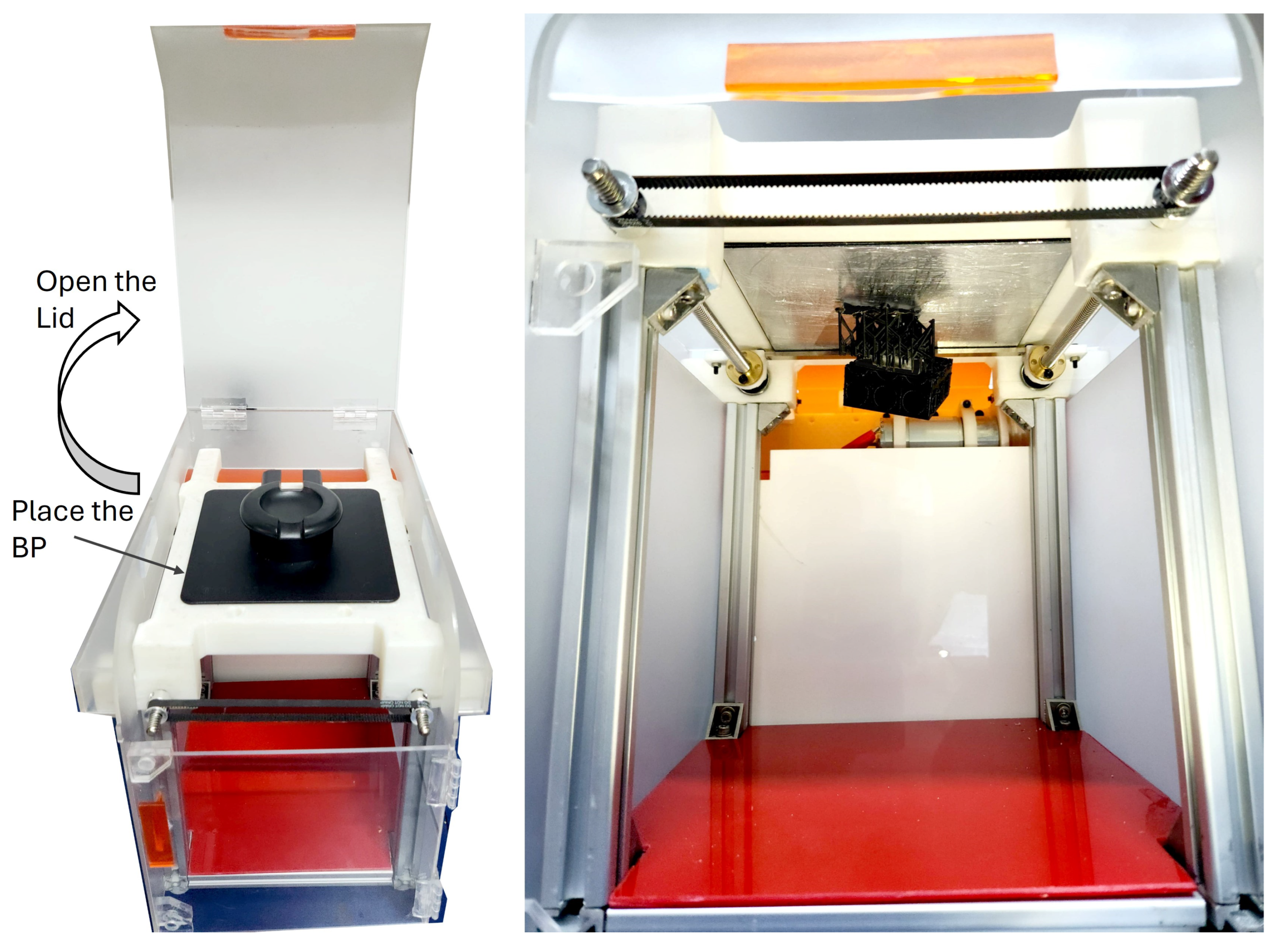
Further, to facilitate ease of mounting the build platform and accessing the separated parts, we modified the design by repositioning the build platform from a vertical to a horizontal orientation, as shown in Figure 7. This adjustment was made to accommodate parts that utilize the entire build volume of the printer. The horizontal orientation also leverages the effect of gravity to assist in the removal process. Once the part is sequentially cut by the sliding blade mechanism, gravity ensures that the part falls onto a soft bed positioned at the bottom, minimizing the risk of damage upon detachment.
To achieve these design requirements, we followed the product design process for designing the form around the mechanism described in the earlier section. Moodboard was created using the semantic differential scale (SDS) to identify the emotion that the product needs to convey (Figure 9). Visual attributes were carefully considered through affinity mapping (Figure 8) to ensure alignment with user needs and preferences. Form exploration sketches (Figure 8) were created to visualize and iterate on design concepts, while a mood board guided the aesthetic direction based on a Semantic Differential Scale (SDS). Subsequently, CAD models were developed and rendered to provide detailed representations of the final design (Figure 10), and a mockup was made to evaluate physical form and ergonomics. The fabricated prototype (Figure 10 and Figure 10) was tested for functionality and usability, ensuring the final product met all design requirements.
5. Performance Testing
The performance of the device was tested using build platforms from Formlabs 3B+ printers™ by varying the parameters such as the size of the parts, the material of the parts and multiple parts with varying geometries on the same platform. A link to the relevant videos is provided for interested readers from which the following observations were made (Google Drive Link).
We conducted tests on a range of part sizes, varying from 10 mm to 100 mm. It was observed that parts of smaller size detached instantaneously compared to larger ones. The parts were fabricated using various standard photo resin print materials provided by Formlabs, viz. Draft, Durable, Tough, Flexible, and Elastic resins, to evaluate the device’s versatility across different young moduli. It was observed that soft materials, such as Flexible, Elastic, and Draft, exhibited a series of progressive failures, whereas stiff materials, such as Tough and Durable resins, showed instantaneous detachment. These observations are in line with our analytical reasoning presented in Section 3. The parameter of raft thickness was determined by Formlabs’ slicing software, PreForm, and remained constant across all parts and materials.
The overall time required for the blade movement, irrespective of the complexity of the geometry or number of parts, was approximately 2 minutes. Since DC motors typically have a monotonically decreasing speed-torque characteristics curve, the above observation implies that the load on the motor did not vary significantly during the diverse experiment scenarios. Progressive failure ensures constancy of applied force for detachment as described in Section 3. Also, this efficiency was achieved with a minimal power requirement of just 12V, demonstrating the energy efficiency of our device.
It was observed that the controlled and consistent force application by the device ensured that parts were removed cleanly and safely from the build platform without damaging either of them. The operation of the device was found to be smooth and noiseless due to the precision of the lead screw mechanism and the stability provided by the guide block.
6. Conclusion
The device implemented the principle of progressive detachment through the wedge effect. The prototype developed and the tests demonstrated that it is a robust, standalone automated solution for the efficient removal of 3D printed parts from build platforms across diverse SLA systems. It accommodates various part sizes, materials, and build platform dimensions, ensuring versatility and broad applicability. The use of product design principles ensures a safe and convenient operation and appropriate form. Efforts are on to extend the concept as an attachment for other types of additive manufacturing machines, such as FDM. Overall, our device offers a safe and reliable solution for the post-processing challenges in 3D printing.
Acknowledgement
The authors would like to acknowledge the contribution of Ms. Srijita Das, M.Des student at the Indian Institute of Technology (IIT) Bombay, for her valuable assistance with the form design.
References
- Drobotov, A.V.; Shemelyunas, S.S. Device for Automatic Removal and Extraction of Printed Parts from the 3D Printer Camera. In Proceedings of the 2021 International Conference on Industrial Engineering, Applications and Manufacturing (ICIEAM). IEEE, 2021, Vol. 8, p. 445–449. [CrossRef]
- Bogue, R. 3D printing: the dawn of a new era in manufacturing?”. Assembly Automation, 33, 307–311.
- Aroca, R.V.; Ventura, C.E.; De Mello, I.; Pazelli, T.F. Sequential additive manufacturing: automatic manipulation of 3D printed parts. Rapid Prototyping Journal 2017, 23, 653–659. [CrossRef]
- Gibson, I. A discussion on the concept of a flexible rapid prototyping cell”. Rapid Prototyping Journal, 2, 32–38.
- Musgrove, H.; Catterton, M.; Pompano, R. Applied tutorial for the design and fabrication of biomicrofluidic devices by resin 3D printing. Analytica Chimica Acta 2022, 1209, 339842. [CrossRef]
- Drobotov, A.; Avdeev, A.; Shvets, A. Analysis of ways to increase the productivity of 3D printing devices for the manufacture of assembly products. Assembly in mechanical engineering, instrument making, pp. 3–6,.
- Shvets, A.; Avdeev, A.; Drobotov, A. Comparative analysis of devices for volumetric printing. VSTU News, 1, 76–79,.
- f, B. AB.Benchof f. Automating 3D Printers with Robots tend.ai. en. Accessed: Oct. 13, June 2016. url: https://hackaday.com/2016/06/27/automating-3d-printers-with-robots/.
- Tsioukas, V.; Pikridas, C.; Karolos, I.A., Challenges, opportunities, and limitations in 3D printing. In 3D Printing: Applications in Medicine and Surgery; Elsevier, 2020; p. 151–155. [CrossRef]
- Shmeleva, A.; Omarov, A.; Shemelyunas, S.; Drobotov, A. Analysis of methods for automatic removal and extraction of printed products from the camera of a 3D printer. VSTU News, 9, 76–78,.
- Avdeev, A.; Shvets, A.; Gushchin, I.; Torubarov, I.; Drobotov, A.; Makarov, A.; Plotnikov, A.; Serdobincev, Y.P. Plot Strength Increasing Additive Manufacturing Fused Filament Fabrication Technology, Based on Spiral Toolpath Material Deposition. Machines:[Open Access Journal, 7, 3,. [CrossRef]
- Brockmeier, O.; Westcott, C.; Bohn, J. Automated loading and unloading of FDM systems”. In Proceedings of the Solid Freeform Fabrication Symposium, Austin, TX; p. 679–686.
- Gibson, I.; Rosen, D.; Stucker, B. Additive Manufacturing Technologies: Rapid Prototyping to Direct Digital Manufacturing; Springer: New York, NY.
- Kumbhakar, P.; Ambekar, R.S.; Mahapatra, P.L.; Sekhar Tiwary, C. Quantifying instant water cleaning efficiency using zinc oxide decorated complex 3D printed porous architectures. Journal of Hazardous Materials 2021, 418, 126383. [CrossRef]
- Li, H.Y.; Ma, Y.; Miswadi, M.N.A.B.; Luu, L.N.N.; Yang, L.; Foong, S.; Soh, G.S.; Sivertsen, E.; Tan, U.X. Detect-Remove-Replace: A Robotic Solution That Enables Unmanned Continuous 3D Printing. IEEE Robotics & Automation Magazine 2022, 29, 33–45. [CrossRef]
- Idris, M.; Seers, T.D.; Alyafei, N. An operational guide to resin 3D printing of geological macromodels. MethodsX 2022, 9, 101863. [CrossRef]
- Dwamena, M. Do Resin 3D Prints Need Supports? How to Do It Like the Pros, 3D Printerly; Vol. 14 Aug www,3dprinterly; p. 3.
| 1 | Indian Patent Application No.: 202441015992 |
Figure 1.
Manual Removal Technique using a spatula.
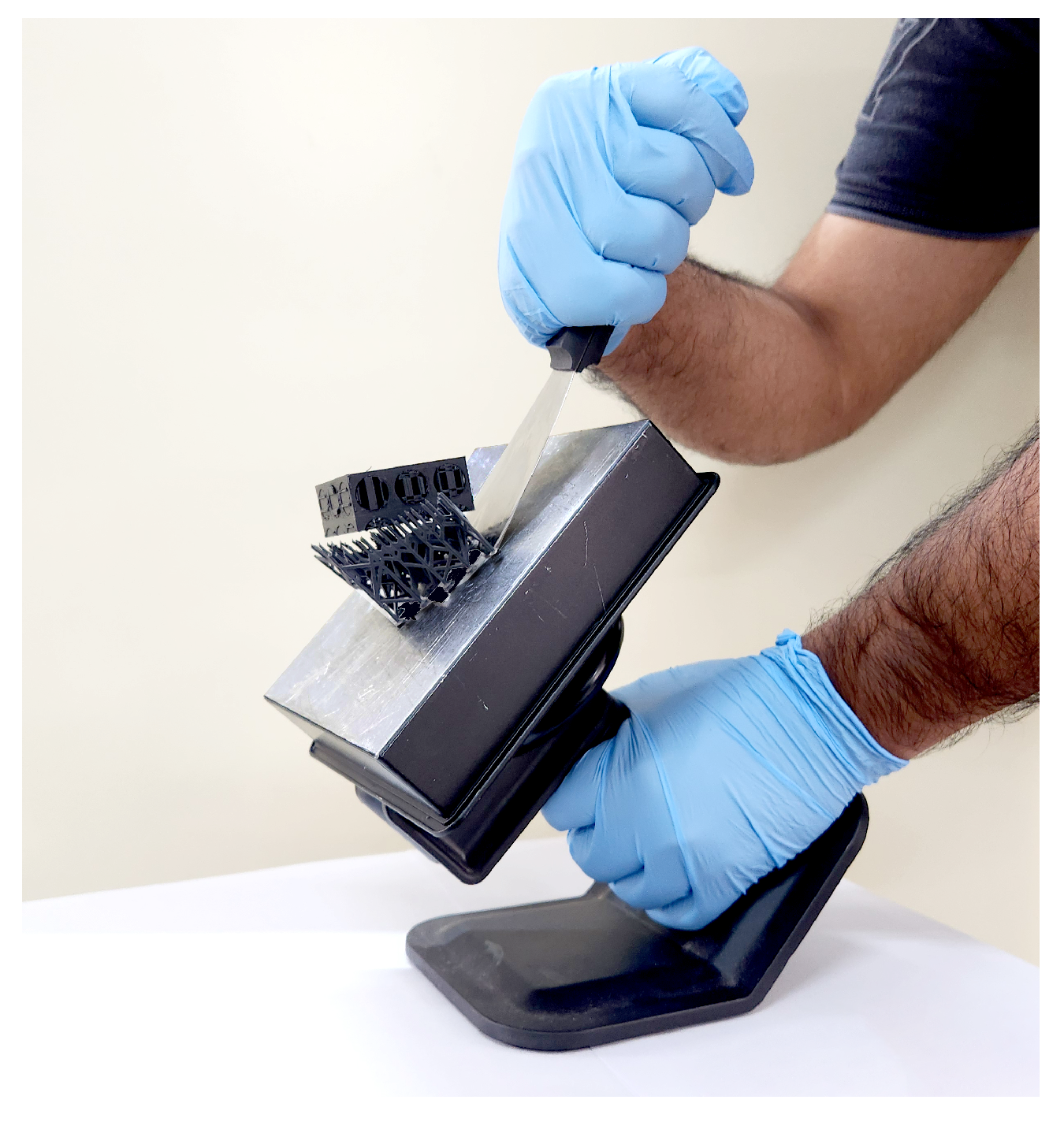
Figure 2.
Integrated Removal Technique using a Flex Plate (Formlabs Build Platform 2.0).
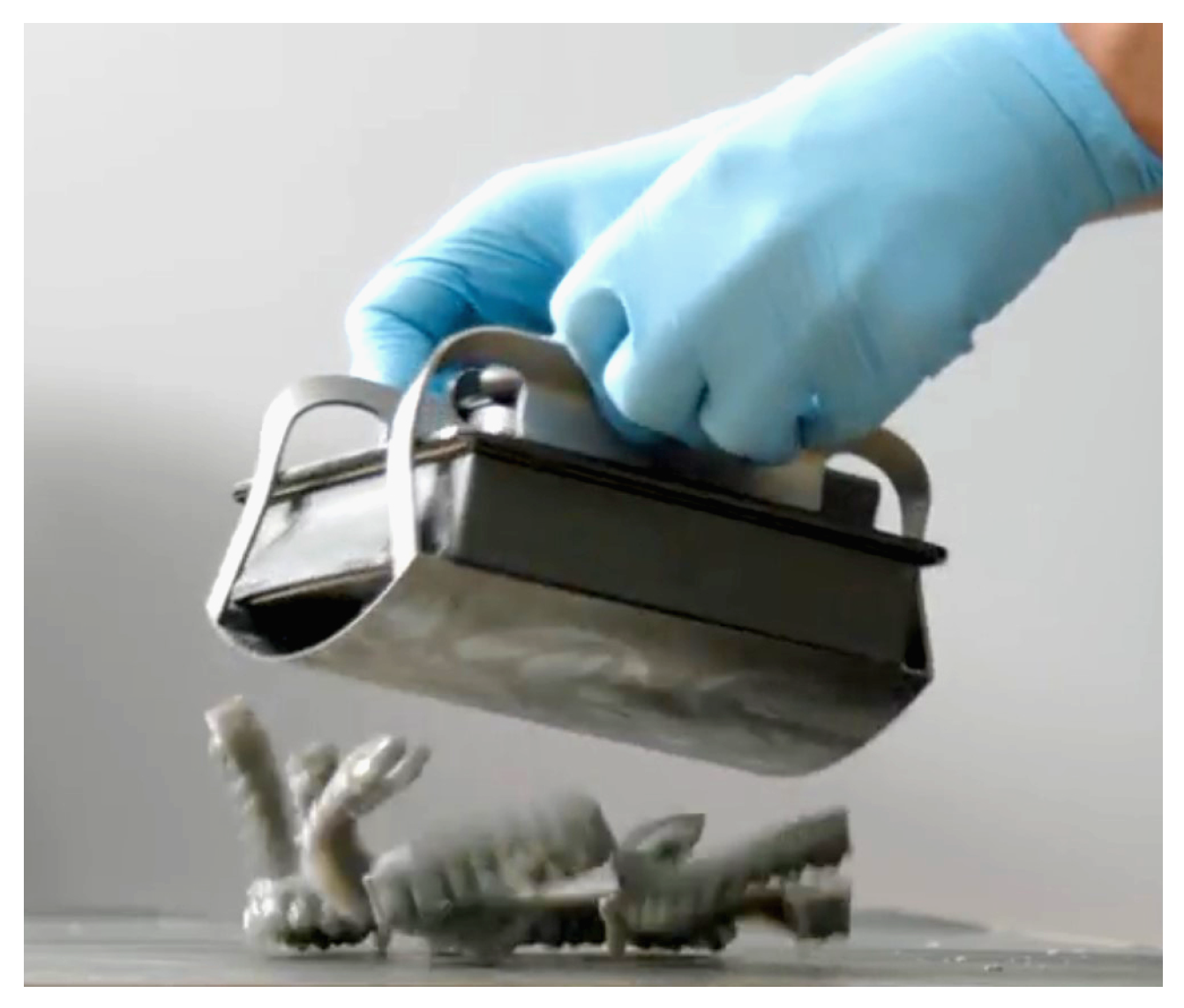
Figure 3.
Model Setup for SLA 3D Printing.
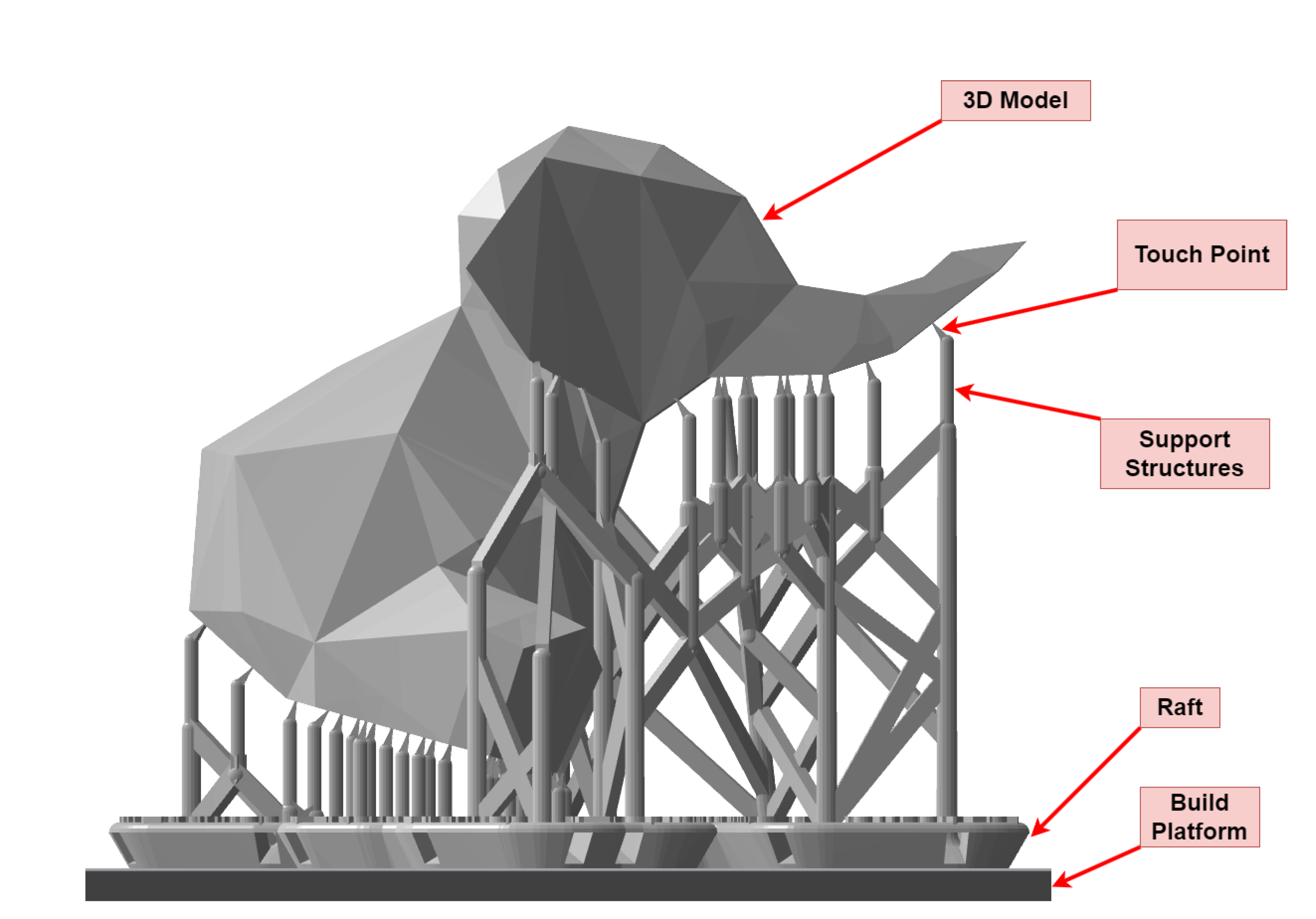
Figure 4.
Different Ways of Applying Forces to Remove the Part.
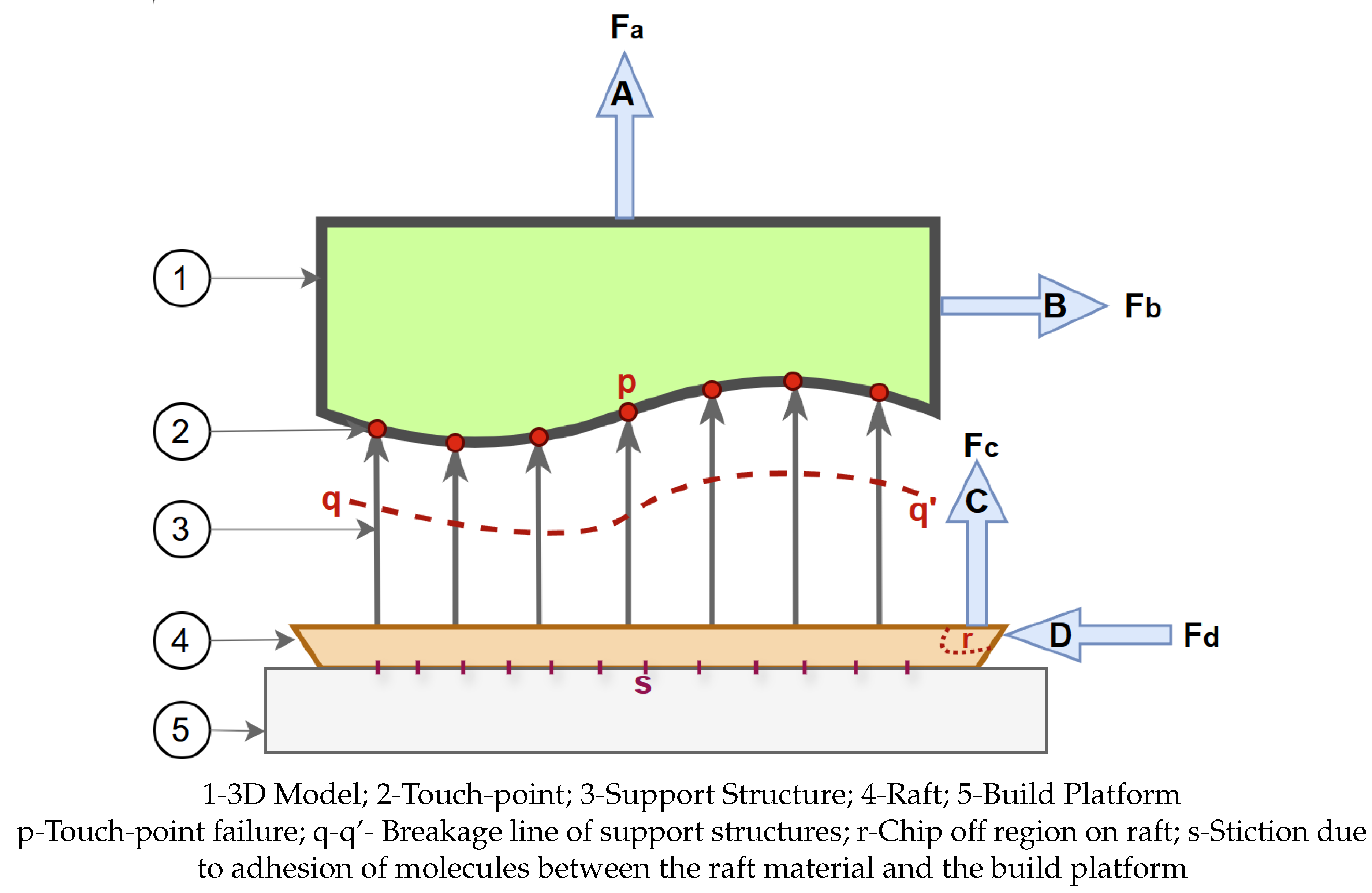
Figure 5.
Optimal Way of Applying Force to Remove the 3D Print form the Build Platform.
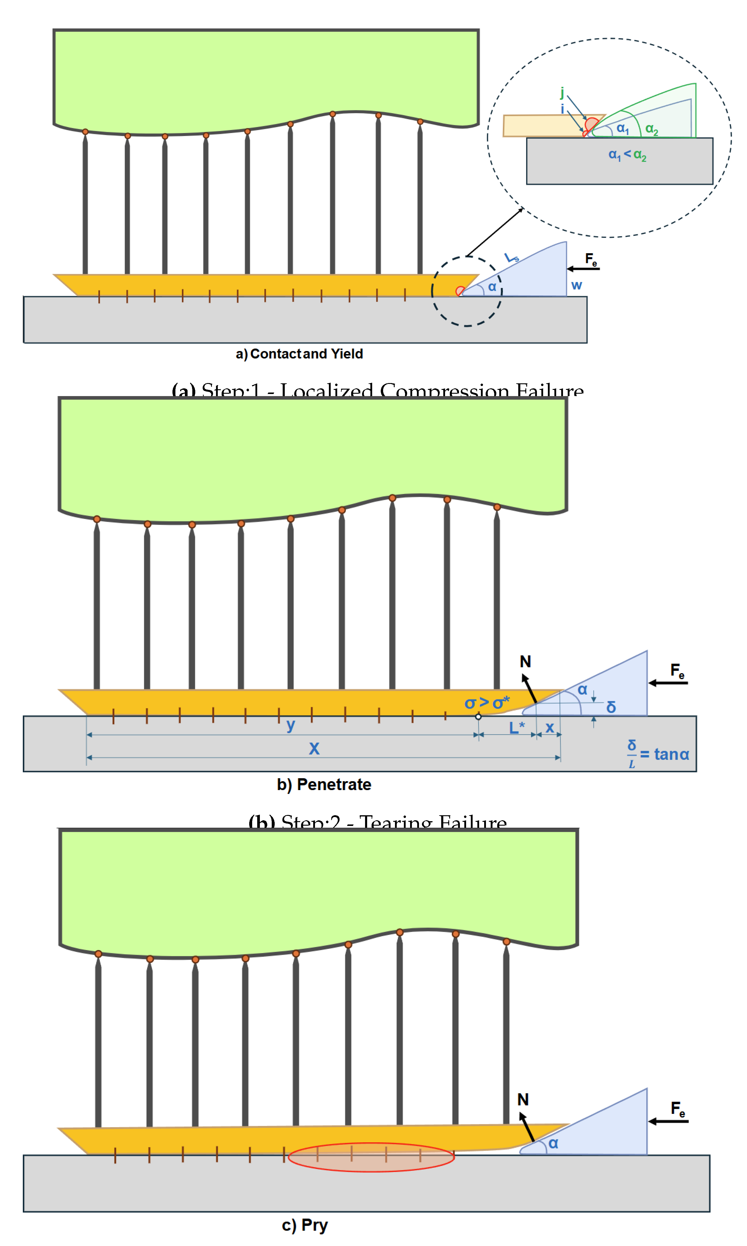
Figure 6.
Blade with Blade Carrier with Wedge Angle and Blade Inclination Angle .
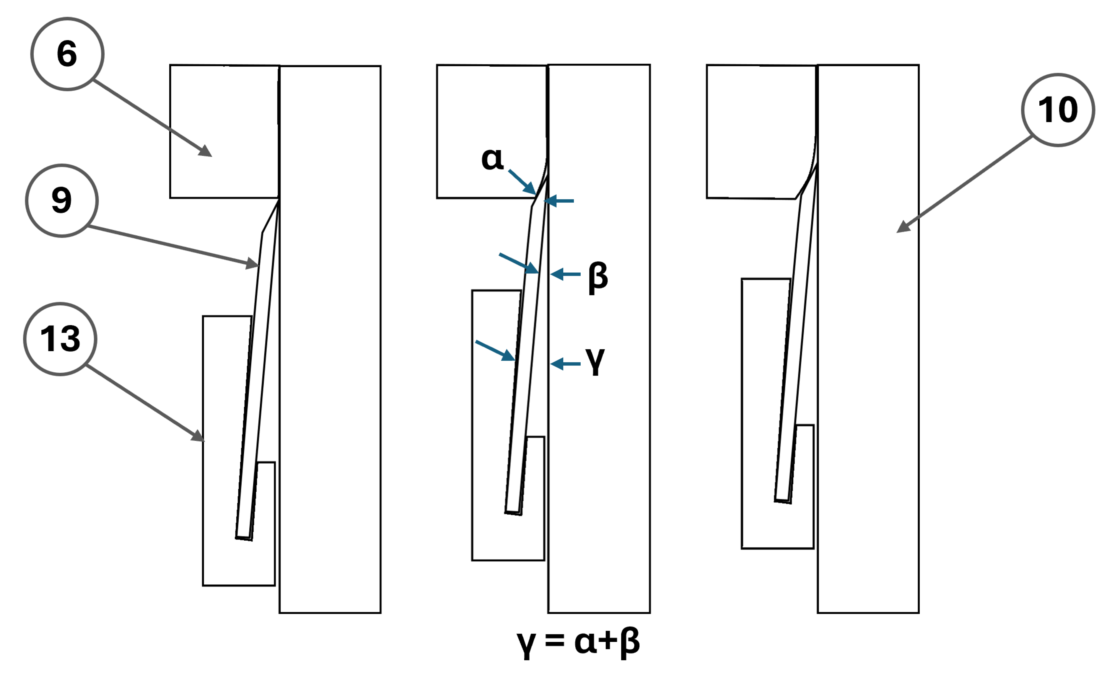
Figure 7.
Prototypes Developed; 1-Circular guide; 2-Pulley; 3-Frame; 4-Motor Drive; 5-Battery; 6-Printed Part; 7-Rope; 8-Guide Block; 9-Blade; 10-Build Platform; 11-Timing Belt; 12-Bearing; 13-Blade Carrier; 14-Lead Screw; 15-Worm Gear Drive; 16-Build Platform Lock; 17-Soft Bed.
Figure 7.
Prototypes Developed; 1-Circular guide; 2-Pulley; 3-Frame; 4-Motor Drive; 5-Battery; 6-Printed Part; 7-Rope; 8-Guide Block; 9-Blade; 10-Build Platform; 11-Timing Belt; 12-Bearing; 13-Blade Carrier; 14-Lead Screw; 15-Worm Gear Drive; 16-Build Platform Lock; 17-Soft Bed.
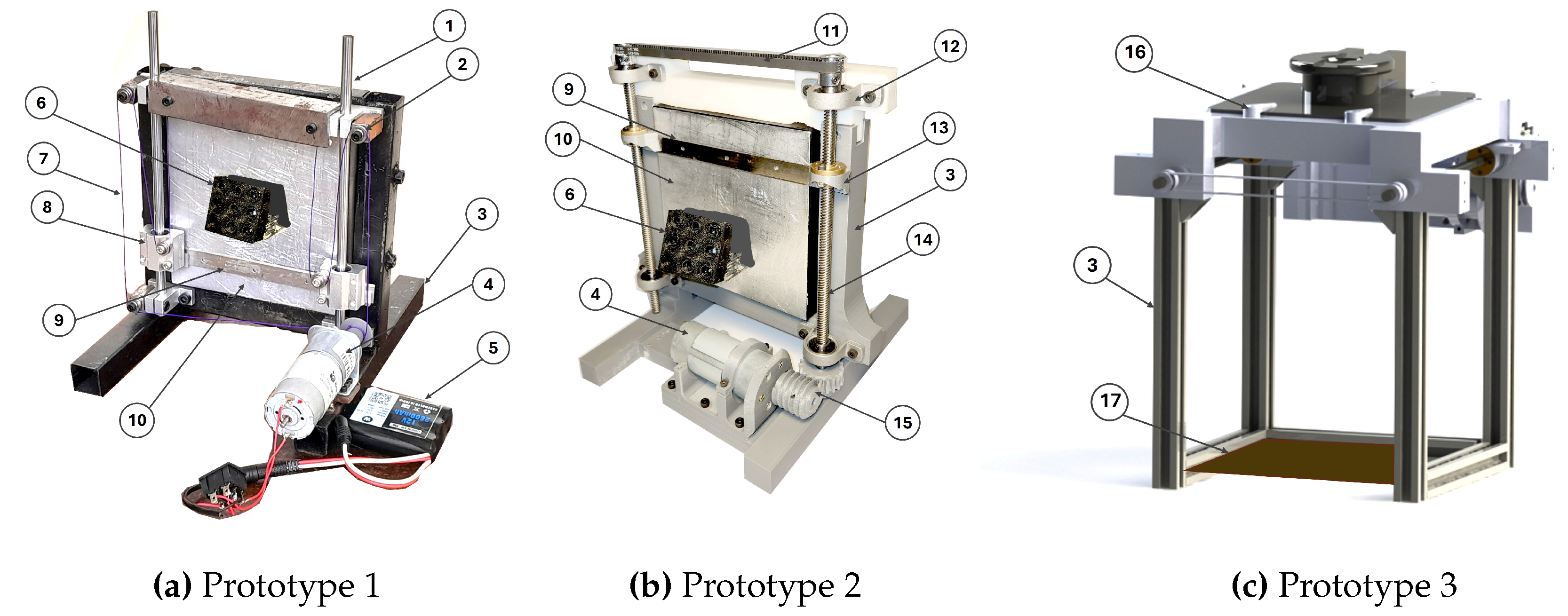
Figure 8.
Concept Design.
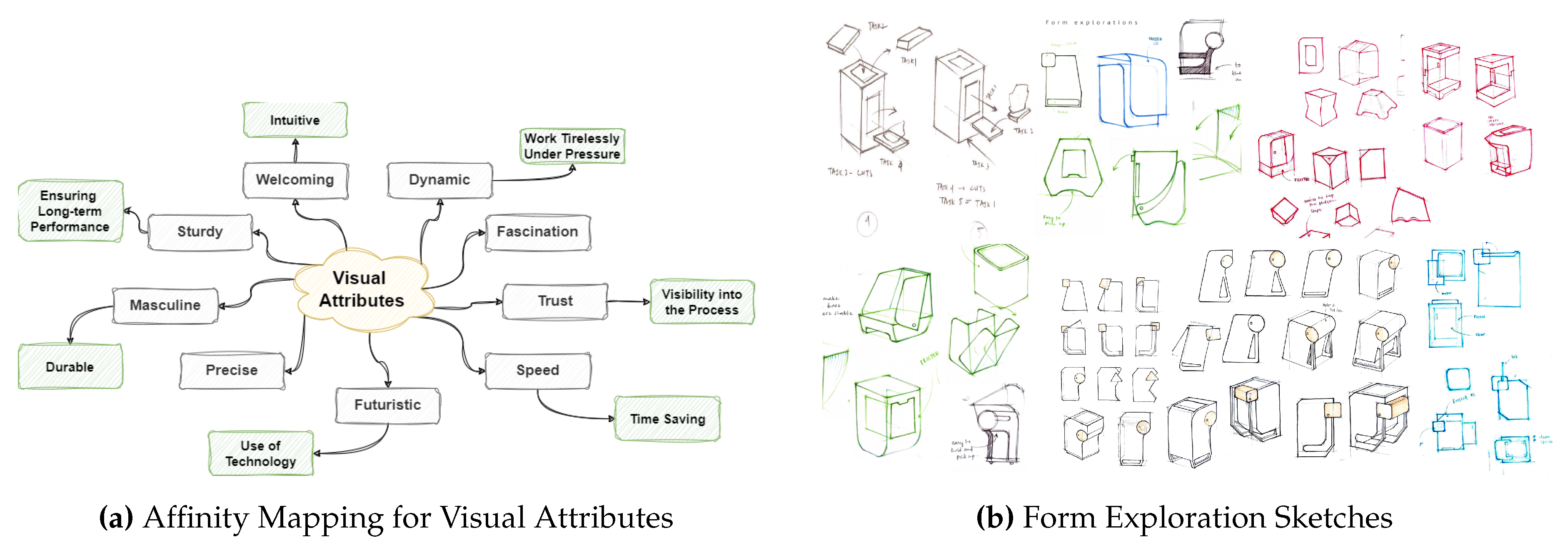
Figure 9.
MoodBoard Created using Semantic Differential Scale.
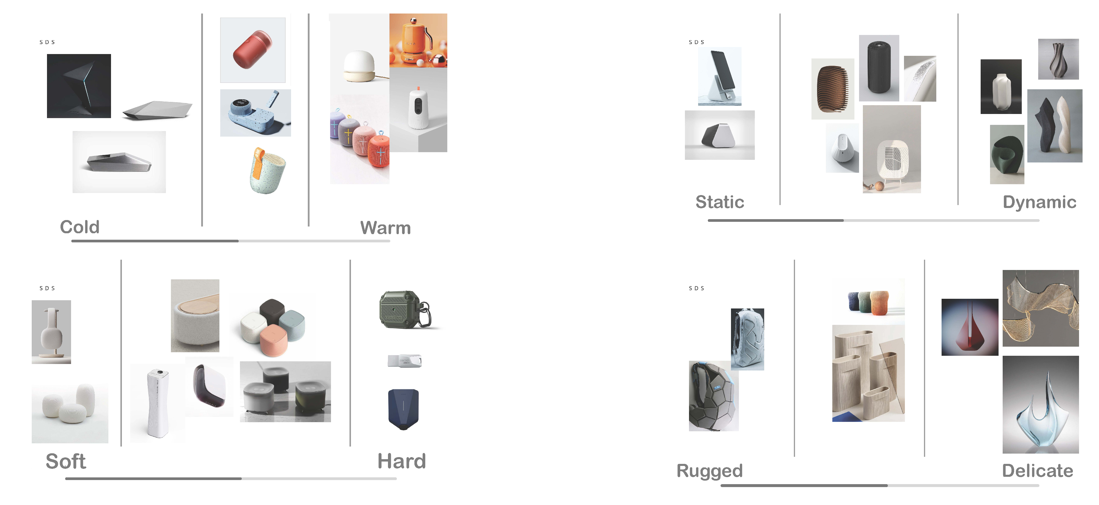
Figure 10.
Fabricated Prototype.
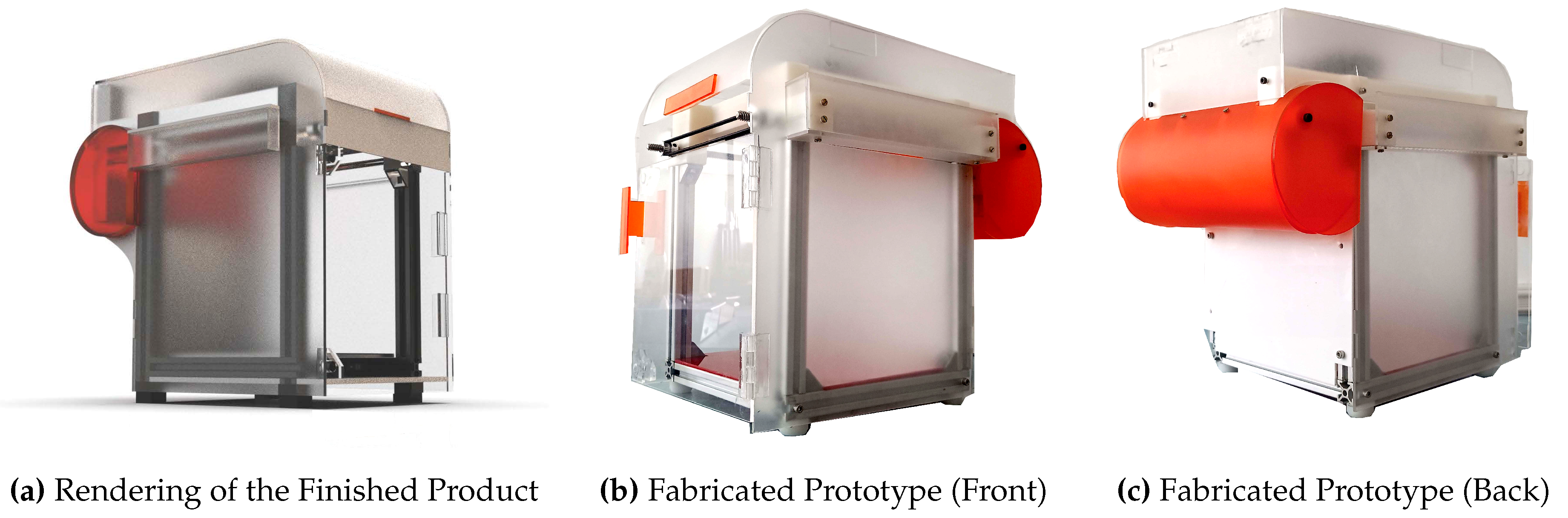
Figure 11.
Performance Testing.
Disclaimer/Publisher’s Note: The statements, opinions and data contained in all publications are solely those of the individual author(s) and contributor(s) and not of MDPI and/or the editor(s). MDPI and/or the editor(s) disclaim responsibility for any injury to people or property resulting from any ideas, methods, instructions or products referred to in the content. |
© 2025 by the authors. Licensee MDPI, Basel, Switzerland. This article is an open access article distributed under the terms and conditions of the Creative Commons Attribution (CC BY) license (http://creativecommons.org/licenses/by/4.0/).
Copyright: This open access article is published under a Creative Commons CC BY 4.0 license, which permit the free download, distribution, and reuse, provided that the author and preprint are cited in any reuse.


