Submitted:
03 January 2025
Posted:
06 January 2025
You are already at the latest version
Abstract
This investigation focuses on selecting catalyst bed loading (CBL) and catalyst size as key design parameters for blowdown propulsion systems, which has a varying effect by propellant tank volumes, injector orifice diameters, and levels of catalyst activity. The catalytic decomposition process of a high-test peroxide (HTP) monopropellant thruster and the stability assessment of the propulsion system were studied using a reduced-order model of the decomposing process of the reactor. Two simplified models were employed to forecast the reactor’s decomposing process and evaluate system stability across various design iterations. The study demonstrated that combustion instability has a higher tendency to manifest during the intermediate phase of the blowdown procedure, notably when the propellant tank pressure ranges from 14 to 10 bar. The optimal system design was determined through this analysis, with CBL of 90 kg/s/m2 and a catalyst diameter of 1.6 mm. An augmentation in the volume of the propellant tank has been shown to improve the overall stability of the system. Conversely, an enlargement of the injector orifice area is likely to induce instability throughout the design space. Furthermore, the degradation of the catalyst—which is characterized by a slight decrease in the active reaction area—contributes to combustion instability, irrespective of the specific design parameters that have been employed.
Keywords:
Hydrogen Peroxide
; Monopropellant thruster
; Reduced-order model
; Catalytic reactor
; Combustion instability
; Parametric study
1. Introduction
In-space propulsion systems frequently employ monopropellant thrusters that adopt a blowdown pressurization mechanism. In this configuration, both the propellant and the pressurant are contained in a single tank, which enhances the system’s simplicity and reliability. As these propulsion systems remain activated for extended periods, there is a gradual decrease in supply pressure, primarily due to the expansion of the ullage volume. This characteristic presents a significant challenge during the later stages of the blowdown operation as the reduced mass flow rate results in attenuated pressure drops throughout the propellant feeding system, which, in turn, triggers the emergence of low-frequency combustion instability.
Combustion instability refers to a periodic fluctuation in pressure within the reaction chamber of liquid propellant rocket engines, where the amplitude surpasses 5% of the average chamber pressure. Specifically, low-frequency combustion instability, often termed chugging instability, is characterized by frequency oscillations within the range of 10-400 Hz. This type of instability is understood to result from the oscillatory interactions that occur between the propellant feeding system and the combustion chamber. Such interactions can give rise to significant structural vibrations, posing a risk of damage to both the spacecraft and its payload, thereby emphasizing the critical need for managing these instabilities in aerospace engineering.
To mitigate these potential issues, common strategies involve crafting a blowdown propulsion system characterized by a low blowdown ratio, defined as the ratio between the initial and final pressures within the tank, and implementing a significant pressure drop across the injection components. The requirement for a decreased blowdown ratio implies the need for a larger initial ullage to accommodate the confined volume of the propellant tank. For the restricted volume available within the tank, this condition would lead to a reduction in the amount of propellant stored, subsequently resulting in a shorter operational lifetime of the system. The increase in pressure drop across the injection components serves to decouple the dynamic behavior of the combustion chamber from the propellant feeding system. If there is an increase in the pressure drop while maintaining a limited tank pressure, it may lead to a decrease in pressure at the reactor and the chamber, which can detrimentally impact the performance of the monopropellant propulsion system.
One potential strategy involves accurately and optimally determining the design configurations of the catalytic reactor within the thruster. This is crucial because the catalytic reactor significantly influences the mechanisms of propellant decomposition and combustion instability, although it does not have a direct impact on the overall layout of the system. Numerous research efforts have been conducted to forecast the behavior of catalytic decomposition processes inside the reactor, as well as to assess the stability of the combustion chamber, all of which have been analyzed under varying design parameters and operational conditions using reduced-order modeling techniques.
Kesten [1], subsequently refined by Sanchez et al. [2], conducted an extensive analytical study aimed at predicting both the steady-state and transient responses of the catalytic reactor in a hydrazine monopropellant thruster. This intricate model, which integrates equations governing species conservation, energy balance, and chemical reactions, demonstrated its ability to accurately forecast the temporal and spatial distribution of temperature and reactants along the reactor’s axis. Notably, the model incorporated the notion of an induction region, predicated on the assumption that at the reactor entrance, all of the energy released from the catalytic decomposition was devoted to vaporizing the liquid-phase propellant. Consequently, the validity of this model is confined to scenarios occurring within the vapor phase region. Moreover, the model did not take into account the transport limitations inherent between the vapor and solid phases. In this context, Hou [3] formulated a model for a hydrazine catalytic reactor that incorporates the complexities of multiphase flow. Hou’s model diverges from Kesten’s approach by factoring in the vaporization alongside the heat and mass transfer phenomena of the species in the liquid phase, thereby enhancing the predictive accuracy at the reactor’s entry point. A reduced-order model focused on the behavior of highly concentrated hydrogen peroxide (HTP) was initially put forward by Pasini [4]; subsequently, it underwent validation through the efforts of Jung [5,6]. In order to simplify the model, the Pasini model made the assumption of a homogeneous multiphase flow. This approach neglected the variations in temperature and species concentration between the bulk flow and the solid catalyst. Subsequently, Jung undertook validation of this model, identifying the reaction rate constants for the catalytic decomposition process by correlating simulated results with experimental data. The aforementioned models demonstrated efficacy in predicting temporal and spatial variations in temperature, pressure, and species concentration. They adequately provided the necessary design parameters to achieve complete decomposition of the propellant, thereby maximizing propellant efficiency. Nonetheless, these models fell short in their capacity to evaluate the stability of the propulsion system.
Multiple research studies have elucidated the connection between the design of catalytic reactors and the stability of combustion processes. In his experimental work, An [7] examined the phenomenon known as chugging instability using HTP monopropellant thrusters. His results indicated that configurations characterized by lower chamber pressure and a larger aspect ratio are more susceptible to experiencing chugging instability. Nonetheless, the scope of this parametric study was constrained due to the limited quantity and range of design variables, a limitation imposed by the expensive nature of conducting experimental investigations. These costs include expenditures related to hot-fire tests and the fabrication of thrusters. Additionally, a complicating factor was that the parameters of interest were intertwined and interdependent, which posed a challenge in discerning a straightforward correlation between the design parameters and the observed instability phenomenon.Pasini [8] conducted hot-fire experimental evaluations utilizing 500 mN HTP monopropellant thrusters and observed a low-frequency combustion instability, which was ultimately responsible for the failure of the propulsion system. Efforts to alter the catalytic reactor’s volume and to modify the pressure drop across the catalyst bed were implemented but did not succeed in alleviating the instability issue.
From a theoretical perspective, numerous studies have approached this subject by carrying out analytical investigations since the 1950s, all focusing primarily on the time lag model as detailed in references [9,10,11,12,13]. This model has significant potential, as it can be employed to forecast the occurrence of chugging instability. This is an analytical framework for investigating combustion instability, which constructs the model based on the holistic phenomenon rather than attempting to represent every individual physical and chemical process. The framework incorporates the notion of a time delay between an arbitrary fluctuation in the flow of propellant being injected and the resultant impact on the combustion chamber’s pressure. Nonetheless, prior research has predominantly centered on assessing how varying operating conditions, such as throttling, the oxygen-to-fuel ratio, and the pressure differential across the injector, influence the stability of combustion. Consequently, there has been only limited exploration into directly correlating the design parameters of the catalytic reactor with both the occurrence and the intensity of the chugging instability.
By integrating reduced-order models concerning the catalytic decomposition process together with the time-lag model utilized for evaluating combustion stability, it becomes feasible to discern the manner in which the design parameters of the catalytic reactor interplay with other configurations of propulsion systems and subsequently influence the overall performance of the blowdown propulsion system. The present investigation focuses on selecting catalyst bed loading (CBL) and catalyst size as key design parameters for blowdown propulsion systems, which vary in tank volumes, injector orifice diameters, and levels of catalyst activity. To conduct a comprehensive parametric analysis, a 90wt.% hydrogen peroxide thruster operating with a blowdown propellant feeding system, characterized by a blowdown ratio of 3.125, was developed and utilized as a baseline for comparison. The evaluation of performance between different scenarios was based on measuring the total impulse generated by the propulsion system, ensuring it operates free from combustion instabilities.
2. Reduced-Order Models
2.1. Catalytic Reactor Model
2.1.1. Model Description
In the current investigation, we employed the reduced-order model as developed by Pasini for the decomposition process of a high-test peroxide (HTP) monopropellant thruster. This model is predicated on several key assumptions: a flow that is one-dimensional, homogeneous, creeping, and consisting of two phases. The molar flow rate for each individual species involved in the reaction can be formulated by considering the specified inlet conditions (refer to Equation (1)) as well as the decomposition parameter, denoted by (see Equation (2)). This approach effectively characterizes the model by illustrating how hydrogen peroxide undergoes decomposition at a particular axial position denoted as x along the flow path.
The decomposition of hydrogen peroxide is characterized by an exothermic reaction. Once the temperature of the liquid mixture achieves the boiling point, the evaporation process commences and persists until the entire liquid fully vaporizes. It is assumed that the resulting two-phase flow, comprising both liquid and gas, manifests as an adiabatic homogeneous flow. The evaporation fraction, denoted by , is presumed to be uniform for both liquid constituents, namely hydrogen peroxide and water, as described in Equation (3).
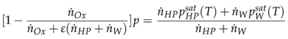
The principles of Dalton’s and Raoult’s laws are applicable for representing the partial pressures associated with gas and vapor species. Consequently, this allows for the determination of the evaporation parameter , which can be obtained through the manipulation of Equation (4).
Energy conservation can be used to identify the temperature of the liquid-gas mixture according to the evaporation parameter, as shown in Equation (5).
From the temperature and evaporation parameters obtained from the relationships stated above, it is possible to identify the volumetric fluxes, bulk flow velocity, and molar concentrations of each species as shown in Equation (6) and Equation (7), respectively.
The decomposition reaction is categorized into two distinct components: catalytic decomposition and thermal decomposition. In the foundational model of Pasini [4], only catalytic decomposition was initially accounted for. However, given the significant impact of vapor hydrogen peroxide decomposition on the sensitive time lag (which is discussed in detail in sec 2.2.1), thermal decomposition has been incorporated into this study for a more comprehensive analysis. The rate of the catalytic decomposition reaction was derived utilizing the Arrhenius equation alongside the Langmuir-Hinshelwood isotherm [4,5,6]. Assuming homogeneous flow within a packed-bed reactor, the hydrogen peroxide concentration in the bulk flow was equated to that on the catalyst surface. Consequently, the reaction rate can be described by Equation (8), where the parameters , , , , and represent the Arrhenius pre-exponential factor, the activation energy for the heterogeneous reaction, the number of active adsorption sites per unit volume of the catalyst bed, the equilibrium constant for surface adsorption, and the specific area of the catalyst, respectively. For this investigation, the reaction constants validated by Jung [6], which are derived from a series of hot-fire test campaigns, were used as a reference. These constants are provided in Table 1 and are pertinent to a 100 N HTP monopropellant thruster employing the catalyst.
The reaction rate of the thermal decomposition can be expressed as Equation (9), where and are the Arrhenius pre-exponential factor and activation energy. The reaction constants are listed in Table 2.
The pressure loss encountered across the catalyst’s packed bed can be determined through application of Ergun’s equation. By incorporating the terms related to the reaction rate along with Ergun’s equation, one can derive the spatial derivative terms for both the decomposition parameter () and the pressure (), as they are detailed in Equation (10) and Equation (11).
In this context, represents the porosity, and denotes the diameter of the catalyst. They are utilized to formulate the specific surface area, expressed as . Consequently, the equations that describe the flow within the catalytic reactor are reformulated as an initial value problem. To accomplish this, the decomposition parameter and the pressure are determined at various sample points along the reactor’s axis, beginning from the inlet, where and . Following this, the temperature, evaporation parameter, molar flow rate, along with other physical properties, are computed at each sample point. This involves utilizing the derivative terms and conservation equations to ensure an accurate representation of the flow dynamics.
2.1.2. Propellant Feeding System
To determine the hydraulic characteristics, specifically the mass flow rate and pressure, throughout the entire propellant feeding system, it is necessary to solve the initial value problem, commencing from the nozzle throat. It should be noted that within the propellant feeding system, the mass flow rate across each hydraulic component (or the cumulative mass flow rates in the event of a branch connection) remains constant, adhering to the principles of steady-state operation. Subsequently, one must estimate the pressure at each hydraulic component, or alternatively, the pressure drop across each component. The flow properties at the exit of the catalytic reactor, aligned with the mass flow rate, can be identified using the compressible isentropic nozzle flow equation. By employing an iterative process in conjunction with the catalytic reactor model, it becomes possible to ascertain the corresponding pressure at the catalytic reactor’s inlet. Once this is established, the pressure drop across the hydraulic components was computed, commencing from the injector face and reconciling this back towards the propellant tank under the assumption that the liquid-phase propellant behaves as an incompressible fluid. It should be noted that in this particular study, the pressure drop across the manifold is deemed negligible. For the line element, the pressure drop calculation is performed applying Equation (12).
In this context, f represents the Darcy friction factor, which can be determined based on the Reynolds number, as described in detail in Equation (13).
In the case of the orifice component, the pressure drop is determined by utilizing Equation (14). Within the scope of this investigation, a discharge coefficient, denoted as , with a value of 0.61, was chosen for the evaluation process. The term representing pressure loss, labeled as , indicates the reduction in pressure experienced within the orifice due to a diminished cross-sectional area. This phenomenon is described through Equation (15). Furthermore, the critical pressure pertains to the pressure differential that corresponds to the Critical Reynolds number, . In this particular study, is set at a value of 150, and the critical pressure can be articulated using the expression provided in Equation (16).
The pressure loss encountered across the filter and valve components is determined utilizing tabulated data from available commercial products. In our analysis, we employed the flow data pertaining to the Swagelok F series, which possesses a nominal pore size of 90 m for the filter, along with the Swagelok 40G series, featuring 3 mm tube connections for both the latch and solenoid valves, to perform the necessary calculations.
2.2. Chugging Instability Model
2.2.1. Model Description
Figure 1 [4] presents an illustration of the physical and chemical processes occurring within the catalytic reactor. When the liquid phase propellant is introduced into the packed-bed catalytic reactor, it undergoes atomization and vaporization, followed by decomposition into hot oxygen gas and water vapor. This product gas is then expelled through a nozzle to generate thrust. The rate at which mass accumulates inside the chamber, which is closely associated with the chamber pressure, is dictated by several factors: the mass flow rate at both the inlet and outlet of the catalytic reactor and the various physical and chemical transformations that facilitate the decomposition of the injected liquid propellant.
In this analysis, the mass flow rate at the injector’s interior surface, denoted as , does not contribute immediately to the mass accumulation within the chamber. Essentially, the modeling framework takes into account the temporal delay between a stochastic fluctuation in the injected propellant flow and the subsequent alterations in the chamber pressure. A total time lag, denoted as , is required to complete both the physical disintegration and chemical reaction processes. This time lag is bifurcated into two distinct components: the insensitive time lag () and the sensitive time lag (). These components are differentiated based on their susceptibility to alteration by the chamber’s physical conditions, particularly temperature and pressure. The insensitive time lag is primarily composed of the atomization and vaporization phases, which remain largely unaffected by these physical conditions. Conversely, the sensitive time lag predominantly consists of the mixing and chemical reaction stages, which are significantly influenced by the conditions within the chamber. Importantly, the remains constant over time and is determined by the fixed reactor design parameters [12]. According to Crocco’s monopropellant time lag chug model [9], the mass balance equation, incorporating the hypothesis of a variable time lag, is represented by Equation (17). In this context, it is essential to ensure that the rate at which decomposition gases are produced matches the combined rate of gases exiting via the nozzle and the accumulation of gas masses within the chamber.
The expression for the accumulation of mass within the catalytic reactor, while maintaining a constant temperature within the chamber, can be determined via pressure measurements as formulated in Equation (18).
The normalized mass accumulation term can be rewritten as Equation (19), using the chamber gas residence time term assuming the chamber gas as an ideal gas.
The term representing the rate of decomposed gas can be articulated as shown in Equation (20). Given that remains constant under a single operational condition, it is possible to recast the normalized form of the decomposed gas rate term as seen in Equation (23). This transformation is achieved by applying the definition of the interaction index (n), which is described in Equation (22) [10]. Within the scope of this research, the interaction index value was set to unity for the purposes of the numerical simulations.
The compressible isentropic nozzle flow equation can provide the approximated expression of the gas ejection rate based on the chamber temperature and pressure as shown in Equation (24). With an appropriate Taylor series expansion and the constant chamber temperature assumption made prior, the normalized gas ejection rate term can be expressed as Equation (26).
The mass balance equation can be rewritten in the Laplace domain as shown in Equation (27).
The oscillatory flow relationship shown in Equation (28) is utilized to derive hydraulic impedance at the injector face expressed in Equation (29). Here, a time-invariant pressure ratio is defined to express the pressure at the injector face using chamber pressure considering the pressure drop across the catalyst bed. Since the time lag of the physical and chemical processes is already accounted for, the phase delay between the pressure perturbations at the injector face and the chamber is neglected.
The system can be considered unstable if an infinitesimal disturbance of the decomposition process, , brings about a significant perturbation of the chamber pressure. Therefore, it is possible to assess the system’s stability by inspecting the value of throughout the Laplace domain as shown in Equation (31).
The characteristic equation of the system, , can be expressed as Equation (32) and the system can be considered unstable if the characteristic equation becomes zero and the real part of the Laplace variables is greater than unity.
The easier method of evaluating the stability of the system is utilizing the bode plot of transfer function , shown in Equation (33) by relocating the terms of the characteristic equation. Here, the system can be considered unstable if the gain of the transfer function is larger than unity when the phase is at or . Here the Laplace variable is .
Then, the stability of the propulsion system can be simply verified by examining a Bode plot, illustrating the gain and phase of the transfer function for the range of . Figure 2.(a) is an example of such a Bode plot with the occurrence of the low-frequency combustion instability. The phase plot is represented between to for simpler representation. Here, the gain value at the phase crossover frequency is beyond unity, indicating that the system definitely possesses a Laplace variable, , which satisfies the Equation (32). It is worth noting that the frequency of the combustion instability does not match the phase crossover frequency unless the gain at the phase crossover frequency equals unity. Likewise, a gain margin obtained from the Bode plot (Figure 2.(b)) can be used to quantify the stability of the system in case combustion instability does not occur.
2.2.2. Inlet Boundary Condition
Hydraulic impedance at the injector face is required to express the system characteristic equation, , and the transfer function, . It is necessary to calculate the hydraulic impedance from the propellant tank throughout every hydraulic element down to the injector’s interior surface. For a pipeline, the relationship between the upstream and downstream impedance can be expressed as Equation (37), where Equation (34) to (36) represent the propagation constant , inertance, capacitance, and resistance terms (L, C, R, respectively), and the characteristic impedance .
The propellant tank can be treated as a large manifold (or a wide closed-line element) and the hydraulic impedance at the entrance of the tank can be expressed as Equation (38). The same approach can be applied for the injector manifold.
Hydraulic elements such as valves and orifices can be expressed as fixed orifices in series connection can be expressed as Equation (39). On the other hand, injector manifold is assumed to be attached to the line element in branch connections, and the downstream impedance can be expressed as Equation (40).
2.2.3. Time Lag Values Estimation
Heidmann [11] suggested that the time required for the vaporization process for the cryogenic propellants equals the time for vaporizing 50% of the mass of the injected droplets. However, since the liquid propellant considered in this study is not cryogenic and the vaporization process is different, the vaporization time was chosen for the duration required to vaporize all liquid phase mixtures. The atomization time was neglected considering the characteristics of the capillary movement and catalytic decomposition of the liquid oxidizer in the packed bed. Therefore, the vaporization time equals the insensitive time lag. From the numerical simulation result, it is possible to identify the axial location where the evaporation parameter becomes 0.99. Then, the insensitive time lag can be calculated as shown in Equation (41).
The sensitive time lag can be derived by subtracting the insensitive time lag from the total time lag. Here, the mixing time lag can be omitted in the case of monopropellant thruster. Hence, the total time lag corresponds to the time required to decompose 99% of the injected mass as shown in Equation (42).
The reduced-order model of the catalytic decomposition described in sec 2.1 was utilized to identify the time lag values according to the design parameters of the reactor at different supply pressures.
3. Parametric Study
3.1. Design of Blowdown Propulsion System
A propellant feeding system of the reference propulsion system was designed as shown in Figure 3. The propulsion system utilizes a blowdown pressurization method, in which the propellant and the pressurant are stored in a single tank. Taking the reference from the ’BT 01/0 - Bladder tank’ of Arianegroup, the net volume of the tank and the initial propellant volume were assumed as 58 liters and 39 liters, respectively. The tank pressure at the beginning of life (BOL) was assumed to be 25 bar and 8 bar at the end of life (EOL), making a blowdown ratio of 3.125. The propulsion system consists of an orbit maneuver thruster (OMT) and attitude control thrusters (ACTs). In this study, only the hydraulic elements that are involved in supplying the propellant into the OMT, marked in red in the figure, were considered for the numerical simulation. Additional hydraulic elements, injector manifold and orifices, were added within the thruster to represent the injector assembly. Here, the diameter of the injector manifold corresponds to the diameter of the catalytic reactor, which alters according to CBL. The geometric configurations of the proposed propellant feeding system are labeled in Table 3.
Due to the blowdown nature of the propulsion system, the tank pressure decays gradually throughout the operation. Also, the bladder of the tank decreases the volume occupied by the remaining propellant. Considering that the propellant tank in space would be covered by a multilayer thermal insulator with electric heaters to maintain a constant temperature, the effect of the heat transfer and the expansion of the pressurant was neglected. Figure 4 illustrates the relationship between the tank pressure and the remaining propellant volume for reference tank ’BT 01/0’. The tank pressure decays down to approximately 8 bar at EOL, resulting in a blowdown ratio of 3.125. By altering the propellant tank design, it is possible to store additional propellant at the cost of an increased blowdown ratio. In such a case, propulsion system would be operated at a lower pressure, inducing lower performance and a higher probability of combustion instability occurrence.
A HTP monopropellant thruster was designed as a reference for the OMT. 90wt.% hydrogen peroxide propellant. A 20 N thrust was assumed to be created at BOL and MnO2/PbO/Al2O3 catalyst was assumed to be used for the thruster, so that the reaction rate constants validated by Jung [9] can be utilized in the study. Equation (43) and (44) were used to identify the performance parameters, vacuum specific impulse () and characteristic velocity (C*), based on the outcomes from the catalytic reactor model. Since the propellant tank, feeding system, and the injector geometries were assumed identical regardless of the CBL and catalyst size, each unique combination of design parameters leads to different mass flow rate, chamber pressure, and thus thrust even at the same tank pressure. Characteristic velocity is dependent on the propellant combination, thus identical throughout the design space.
In this research, a nozzle expansion ratio () of 60 was presumed for the monopropellant thruster, based on the 20 N Hydrazine monopropellant thruster by Arianegroup. With a fixed , the ratio of the exit exhaust gas pressure to the chamber pressure () specified in Equation (43) remains unchanged throughout the blowdown operation, as described in Equation (45). The second term in Equation (43), which represents the pressure effect of the exhaust gas at the nozzle exit, exhibits minimal variation with respect to the chamber pressure. Consequently, the vacuum specific impulse of the thruster remains constant irrespective of CBL, catalyst size, or the stage of blowdown operation, provided the injected propellant is completely decomposed.
Figure 5 depicts the numerical simulation workflow for determining the geometric specifications of a catalytic reactor and evaluating the propulsion system’s performance and response during a blowdown operation. By using predefined parameters such as CBL, catalyst size, and propellant feeding system configurations, one can ascertain the necessary nozzle throat area and reactor length to produce a 20 N thrust at BOL and ensure complete decomposition of the injected propellant at both BOL and EOL. Notably, the catalytic reactor length is optimized to avoid introducing extra pressure drops. Assuming steady state conditions, the mass flow rates of the liquid phase in the feeding system and the gaseous products at the nozzle throat are equal. The compressible isentropic flow equation at the nozzle throat, denoted as Equation (46), is subsequently compared to the initial estimate and refined through an iterative process.
For the parametric investigation, CBLs ranging from 50 to 150 kg/s/m2 and catalyst diameters between 0.8 and 2.0 mm were selected based on previously validated designs [cite]. As reviewed in the literature, most cases utilized a CBL starting from 50 kg/s/m2, with higher CBLs being employed in bipropellant applications [Sisco]. Reported aspect ratios typically vary from 0.5 to 2.0. Figure 6 (a) through (d) depict the geometric configurations of the catalytic reactor and nozzle, alongside the specific impulse and generated thrust at BOL conditions in relation to the CBL and catalyst size. As shown in Figure 6 (a), the aspect ratio of the designs aligns with the reported cases. Figure 6 (b) reveals that the nozzle throat area expands with smaller catalyst sizes and higher CBLs. Given the minimal variations in specific impulse (Figure 6 (c)) and the thrust deviation maintained within ±0.5 N (Figure 6 (d)), the throat area increase is necessary to accommodate the required propellant mass flow rate despite the high pressure drop in reactors with small catalysts and high CBLs.
The pressures and pressure drops across the hydraulic components of the propellant feeding system and the catalytic reactor at BOL are presented in Table 4. At BOL, the variance in mass flow rates with respect to CBL and catalyst size is minimal, thus the case CBL=50 kg/s/m2, =1 mm is depicted in the table. The quantity and dimensions of the injector orifices were designed to meet the typical design criteria for a deep-throttling rocket engine, where the pressure drop across the injector plate is roughly 30% of the chamber pressure [Sutton].
3.2. Results
3.2.1. Reference Propulsion System
Figure 7 shows the gain margin of various combinations involving CBL, catalyst diameter, and tank pressure. The black spots indicate instances of combustion instability. In the reference propulsion system, combustion instability is anticipated at a CBL of 150 kg/s/m2 and a catalyst diameter of 100 mm when the tank pressure ranges from 14 to 10 bar. Contrary to the widespread assumption that low-frequency combustion instability emerges at the end of blowdown operations, it is observed that under different CBL conditions, the smallest gain margin is expected midway through the blowdown, particularly at tank pressures from 15 to 10 bar. This may be attributed to the parameter in Equation (33). Despite a diminished pressure perturbation amplitude, , resulting from a reduced mass flow rate and consequently smaller pressure drop across the propellant feeding system, the decreased catalyst reactor inlet pressure, , adequately suppresses the transfer function gain, thus enhancing the gain margin. However, when operating at a tank pressure between 15 to 10 bar, the pressure is insufficiently low to suppress the augmented pressure perturbations at the catalyst reactor inlet. Moreover, it is observed that the system is prone to greater instability with a higher CBL and smaller catalyst diameter. The increased CBL and smaller catalyst diameter lead to a greater pressure drop across the reactor. To produce the required 20 N of thrust at BOL, the catalyst reactor inlet pressure becomes elevated, thus failing to mitigate the pressure perturbation term.
Figure 8 illustrates the thrust generated and vacuum specific impulse of the thruster designs as a function of tank pressure. As previously discussed, for a fixed , the specific impulse remains constant, independent of the CBL, catalyst size, or chamber pressure, as shown in Figure 8(b). With the gradual decline in mass flow rate due to decreasing tank pressure, it can be observed that the thrust output by the reactor is primarily a function of propellant tank pressure, and remains largely consistent regardless of CBL or Dp. As noted in Section 1, evaluating the performance of each design involves determining the total impulse a propulsion system can generate without experiencing combustion instability. Given that thrust is dictated solely by propellant tank pressure, this evaluation can be readily conducted by examining the range of tank pressures that avoid inducing combustion instability.
Moreover, one can determine the effectiveness of stable designs by evaluating the minimum gain margin throughout the blowdown process. The design that achieves the highest value for the ’minimum gain margin during the blowdown process’ is identified as the optimal solution. In the case of the reference propulsion system, the optimal design leads to the minimum gain margin of 0.087 when CBL equals 90 kg/s/m2 and Dp is 1.6 mm.
3.2.2. Effect of Injector Orifice Area
In this parametric investigation, the injector orifice count specified in Table 3 is augmented from 7 to 8, thereby increasing the total injector orifice area by roughly 15%. This modification leads to the estimation of the pressure drop throughout the propellant feeding system’s hydraulic elements, depicted in Table 5. Pressure drop variations from the reference propulsion system are largely negligible, aside from the orifice, which experienced an approximate 22% reduction down to 4 bar. The pressure drop across the expanded injector orifices is about 22% of the chamber pressure, aligning with the general rocket engine criteria outlined in previous studies [14]. Conversely, the response of the system illustrated in Figure 9 displays a significant deviation from the reference propulsion system. Combustion instability is anticipated across a broad spectrum of blowdown operations, with propellant tank pressures ranging from 20 to 10 bar, which encompasses the majority of the blowdown propulsion system’s operational timeline. This indicates that the increased injector orifice area causing a pressure reduction down to 22% of chamber pressure is inadequate for in-space propulsion applications, irrespective of CBL and catalyst dimensions. Even with the expanded orifice area cases, the tendency of the system to be more unstable as the increase of CBL and decrease in catalyst diameter can be witnessed.
3.2.3. Effect of Propellant Tank Net Volume
In this parametric study, the propellant tank was substituted with a larger volume model, using ’DT 01/0 - Diaphragm tank’ by Arianegroup as a benchmark. The tank’s net volume and the starting propellant volume were postulated to be 180 liters and 132 liters, respectively. Much like in the bladder tank, the diaphragm tank reduces in volume, accommodating the leftover propellant as the tank pressure diminishes. Similarly, the influence of heat transfer and pressurant expansion was disregarded. Figure 10 demonstrates the correlation between tank pressure and remaining propellant volume for the baseline ’DT 01/0’ tank. The tank pressure decreases to roughly 6.4 bar at EOL, yielding a blowdown ratio of 3.91; however, for comparison ease, the blowdown ratio was intentionally matched with the reference propulsion system.
Figure 11 illustrates that employing a propellant tank with increased volume effectively reduces or alleviates combustion instability throughout the entire design space. It is observed that combustion instability arises at CBL = 150, Dp = 0.8 mm at 11 bar, consistent with the reference propulsion system. The tank volume does not impact the pressure drop in the propellant feeding system or the catalytic reactor’s system response. Consequently, the general enhancement of gain margin is likely attributable to variations in hydraulic impedance, , as expressed in Equation (33).
Figure 12 (a) and (b) illustrate the comparative analysis of hydraulic admittance, which is the reciprocal of hydraulic impedance, whereas (c) and (d) present the corresponding Bode plot response of the system. This analysis is for a CBL of 90 kg/s/m2 and a Dp of 1 mm at a pressure of 15 bar from two propellant tanks. The variations between the two scenarios are minimal; nonetheless, it is noticeable that the gain Bode plot for both admittance and the propulsion system appears to shift marginally towards lower frequencies with an increase in the tank volume, while the phase crossover frequency remains constant. Consequently, the difference between unity and gain at the phase crossover frequency, known as the gain margin, rises as the propellant tank volume grows.
3.2.4. Effect of Catalyst Activity
In the final parametric analysis, the degradation of the catalyst was considered to evaluate its impact on the blowdown propulsion system’s performance. Prolonged catalyst operation might compromise its structural integrity, resulting in a reduced specific surface area for reactant adsorption/desorption in catalytic decomposition. To simulate this specific surface area reduction, the number of active adsorption sites per unit volume, denoted as in Equation (8), was reduced to 80% of that of the reference propulsion system. Figure 13 depicts the response of the propulsion system related to CBL and Dp during the blowdown process. Consistent with the previous study, combustion instability is anticipated within the propellant tank pressure range of 15 to 10 bar, independent of the design parameters. Additionally, it is observed that an increased CBL and a reduced catalyst diameter provoke the instability. Therefore, it is essential that the catalyst retains its ability to decompose until the tank pressure drops to a minimum of 10 bar. For the reference propulsion system, this corresponds to having 14 L of propellant left, equating to 65% consumption of the initial propellant.
4. Discussion and Conclusion
This investigation involved a parametric analysis to determine how CBL and catalyst size impact the performance of a propulsion system operating under blowdown conditions. Two simplified models were employed to forecast the reactor’s decomposition process and evaluate system stability across various design iterations. A reference blowdown propulsion system was created to evaluate its performance in relation to the design parameters. The study demonstrated that combustion instability has a higher tendency to manifest during the intermediate phase of the blowdown procedure, notably when the propellant tank pressure ranges from 14 to 10 bar. The likelihood of this instability is governed by the relationship between the pressure levels and the pressure fluctuations experienced at the inlet of the catalytic reactor. To evaluate the efficiency of the propulsion system, comparisons were made by measuring the total impulse generated in the absence of combustion instability. As the investigation employed the fixed value for the nozzle expansion ratio, thus identical specific impulse, the comparison was easily made by comparing the range of propellant tank pressure that does not cause the incursion of the combustion instability. Through this analysis, the optimal system design was determined, with parameters set at a coolant bulk load (CBL) of 90 kg/s/m2 and a particle diameter (Dp) of 1.6 mm. Subsequent parametric studies were performed to explore the impact of the injector orifice area, propellant tank volume, and catalyst activity upon the propulsion system. By marginally increasing the injector orifice area, which alters the pressure drop ratio from the injector orifice to the chamber from 30% to 22%, the propulsion system would likely encounter combustion instability spanning the entire design space for the majority of operational phases. This observation aligns with the conventional method employed to counteract combustion instability, which involves imposing a substantial pressure drop on the injection elements to effectively disengage the combustion chamber dynamics from those of the propellant feeding system. This research reaffirmed the finding that even a modest reduction in pressure at the injector orifice can have a notable impact on the stability of the blowdown operation. It is crucial to note that while increasing the pressure drop across the injection components presents itself as a potential solution, an excessive pressure drop can restrict the mass flow rate, thus hindering the achievement of necessary thrust levels. Within the context of this study, a prudent recommendation is a pressure drop amounting to 30% of the chamber pressure, which can serve as a guideline for designing thrusters intended for blowdown operation purposes. Increasing the dimensions of the propellant tank resulted in minor variations in overall stability; nevertheless, a notable enhancement in the gain margin was observed across the entire design space. When considering the scenario of diminished catalyst activity, it was hypothesized that there would be a decrease in the number of active adsorption sites available per unit volume. This assumption stems from the reduced structural integrity of the catalyst, which can occur as a consequence of the extended operational period of the propulsion system. The findings demonstrate that the propulsion system encounters combustion instability when subject to a 20% reduction, particularly within the propellant tank pressure range of 15 to 10 bar, and this occurs regardless of the specific design parameters implemented. From this, it is possible to deduce a requirement concerning the quality of the catalyst. It must maintain efficacy until the propellant tank pressure diminishes to a level as low as 10 bar, which correlates to the duration necessary to deplete 65% of the initial propellant reserves.
Funding
This project has received funding from the European Union’s Horizon 2020 research and innovation programme under the Marie Skłodowska-Curie grant agreement No 101110555.

Data Availability Statement
The data presented in this study are available on request from the corresponding author.
Conflicts of Interest
No conflict of interest exists in the submission of this manuscript, and the manuscript is approved by all authors for publication. I would like to declare on behalf of my co-authors that the work described was original research that has not been published previously, and is not under consideration for publication elsewhere, in whole or in part.
References
- Kesten, A. Analytical Study of catalytic reactors for hydrazine decomposition. NASA United Aircraft Research Laboratories G-910461 1968, pp. 1–9.
- Sanchez Tarifa, C.; Urrutia Pombo, J.L.; Linan Martinez, A.; Crespo Martinez, A.; Fraga, E. Development of an analytical model of hydrazine decomposition motors. Technical report, 1975.
- Hou, B.; Wang, X.; Li, T.; Zhang, T. Steady-State Behavior of Liquid Fuel Hydrazine Decomposition in Packed Bed. AICHE Journal 2015, 61, 857–866. [Google Scholar] [CrossRef]
- Pasini, A.; Torre, L.; Romeo, L.; Cervone, A.; d’Agostino, L. Reduced-Order Model for H2O2 Catalytic Reactor Performance Analysis. Journal of Propulsion and Power 2010, 26, 446–453. [Google Scholar] [CrossRef]
- Jung, S.; Choi, S.; Kwon, S. Design optimization of green monopropellant thruster catalyst beds using catalytic decomposition modeling. 53rd AIAA/SAE/ASEE Joint Propulsion Conference, 2017 2017, pp. 1–10. [CrossRef]
- Jung, S.; Choi, S.; Heo, S.; Kwon, S. Scaling of catalyst bed for hydrogen peroxide monopropellant thrusters using catalytic decomposition modeling. Acta Astronautica 2021, 187, 167–180. [Google Scholar] [CrossRef]
- An, S.; Jin, J.; Lee, J.; Jo, S.; Park, D.; Kwon, S. Chugging Instability of H2O2 Monopropellant Thrusters with Reactor Aspect Ratio and Pressures. Journal of Propulsion and Power 2011, 27, 422–427. [Google Scholar] [CrossRef]
- Pasini, A.; Calatafimi, S.; Puccinelli, E.; Muñoz Moya, C.; Saryczew, J.; Searle, T. Influence of Catalytic Bed Configuration on the Unsteady Behaviour of 500 mN HTP Thruster. Space Propulsion 2024 2024. [Google Scholar]
- Crocco, L. Aspects of Combustion Stability in Liquid Propellant Rocket Motors Part1: Fundamentals. Low frequency instability with monopropellants. J. of American Rocket Society 1951, 8, 163–178. [Google Scholar] [CrossRef]
- Crocco, L.; Cheng, S.I. Theory of Combustion Instability in Liquid Propellant Rocket Motors; 1956. [CrossRef]
- Szuch, J. Digital computer program for analysis of chugging instabilities. Technical Report December, 1970.
- Casiano, M. Extensions to the time lag models for practical application to rocket engine stability design. PhD thesis, 2010.
- Natanzon, M.S. Low Frequency Oscillations in Liquid Rocket Combustion Chambers. In Combustion Instability; American Institute of Aeronautics and Astronautics: Reston ,VA, 2008; pp. 1–42. [CrossRef]
- Sutton, G.P.; Biblarz, O. Rocket Propulsion Elements; John Wiley \& Sons, 2010.
Figure 1.
Schematic of physical and chemical processes within the catalytic reactor
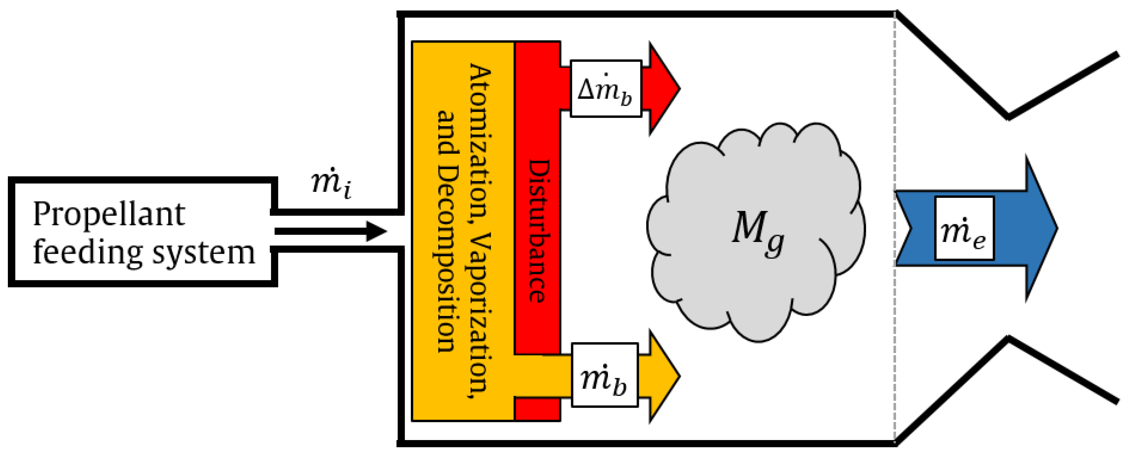
Figure 2.
Bode plot of the system response and stability assessment criteria
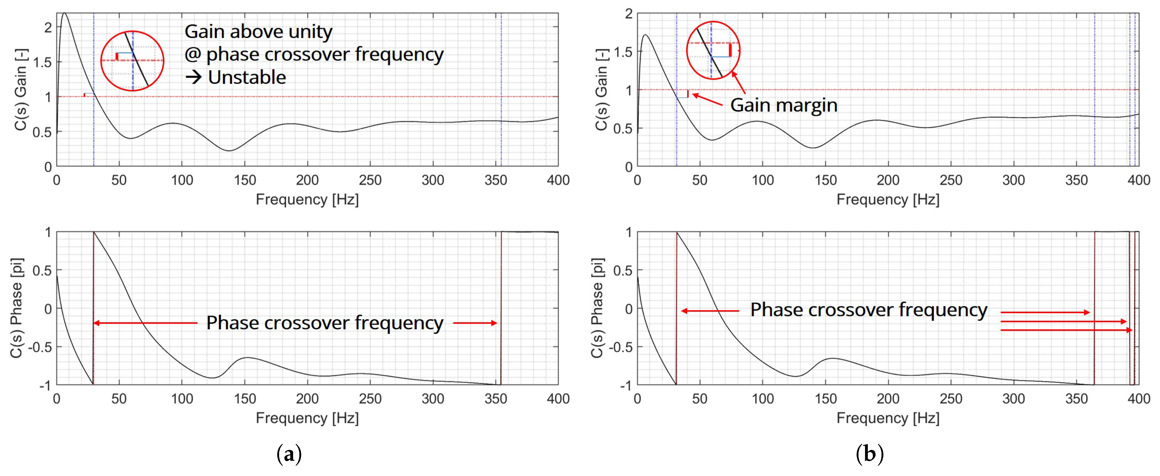
Figure 3.
Schematics of the reference 20 N HTP monopropellant propulsion system
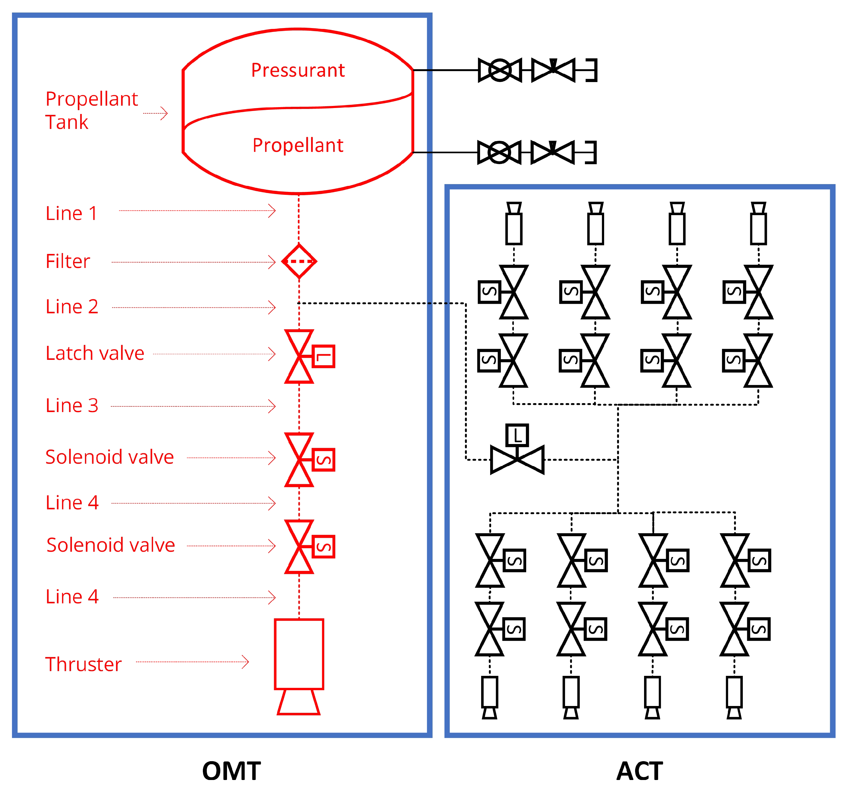
Figure 4.
Blowdown tank pressure to the remaining propellant volume for BT 01/0 propellant tank
Figure 5.
Flow chart of the numerical simulation
Figure 6.
Geometric configurations and performance according to design parameters
Figure 7.
Gain margin of reference propulsion system
Figure 8.
Thrust and Specific impulse of the reference propulsion system
Figure 9.
Gain margin of reference propulsion system
Figure 10.
Blowdown tank pressure to the remaining propellant volume for DT 01/0 propellant tank
Figure 11.
Gain margin of expanded propellant tank volume propulsion system
Figure 12.
Geometric configurations and performance according to design parameters
Figure 13.
Gain margin of reference propulsion system

Table 1.
Reaction constants for hydrogen peroxide catalytic decomposition with catalyst
| Reaction constants | Value |
|---|---|
| 15,000 kJ/kmol | |
| 19.794 kmol/ · s | |
| 625 1/ | |
| 1 |
Table 2.
Reaction constants for hydrogen peroxide thermal decomposition
| Reaction constants | Value |
|---|---|
| 1 × kJ/kmol | |
| 2.0083 × kmol/· s |
Table 3.
Propellant feeding system specification
| Element type | Number of Elements | Length (mm) | Diameter (mm) |
|---|---|---|---|
| Propellant tank | 1 | - | - |
| Line 1 | 1 | 1000 | 4 |
| Filter | 1 | 50 | 2.4 |
| Line 2 | 1 | 500 | 1.4 |
| Latch valve | 1 | 17 | 2.4 |
| Line 3 | 1 | 500 | 1.4 |
| Solenoid valve 1 | 1 | 17 | 2.36 |
| Line 4 | 1 | 30 | 1.4 |
| Solenoid valve 2 | 1 | 17 | 2.36 |
| Line 5 | 1 | 30 | 1.4 |
| Injector manifold | 1 | 10 | |
| Orifice | 7 | 1 | 0.3 |
Table 4.
Pressure and pressure drop of reference propulsion system at BOL (CBL = 50, Dp=1.0 mm)
| Element type | Pressure (bar) | Pressure drop (bar) |
|---|---|---|
| Propellant tank | 25 | - |
| Line 1 | 24.9688 | 0.0312 |
| Filter | 24.5205 | 0.4483 |
| Line 2 | 23.9594 | 0.5610 |
| Latch valve | 23.8066 | 0.1528 |
| Line 3 | 23.2456 | 0.5610 |
| Solenoid valve 1 | 23.0928 | 0.1528 |
| Line 4 | 23.0591 | 0.0337 |
| Solenoid valve 2 | 22.9063 | 0.1528 |
| Line 5 | 22.7724 | 0.1339 |
| Injector manifold | 22.7724 | 0 |
| Orifice | 17.5787 | 5.1937 |
| Catalyst reactor | 16.7868 | 0.6775 |
Table 5.
Pressure and pressure drop with increased injector orifice area at BOL (CBL = 50, Dp=1.0 mm)
Table 5.
Pressure and pressure drop with increased injector orifice area at BOL (CBL = 50, Dp=1.0 mm)
| Element type | Number of Elements | Pressure (bar) | Pressure drop (bar) |
|---|---|---|---|
| Propellant tank | 1 | 25 | - |
| Line 1 | 1 | 24.9682 | 0.0318 |
| Filter | 1 | 24.5154 | 0.4528 |
| Line 2 | 1 | 23.9444 | 0.5709 |
| Latch valve | 1 | 23.7901 | 0.1544 |
| Line 3 | 1 | 23.2191 | 0.5709 |
| Solenoid valve 1 | 1 | 23.0647 | 0.1544 |
| Line 4 | 1 | 23.0305 | 0.0343 |
| Solenoid valve 2 | 1 | 22.8761 | 0.1544 |
| Line 5 | 1 | 22.7396 | 0.1365 |
| Injector manifold | 1 | 22.7396 | 0 |
| Orifice | 8 | 18.6838 | 4.0558 |
| Catalyst reactor | 1 | 18.2888 | 0.3950 |
Disclaimer/Publisher’s Note: The statements, opinions and data contained in all publications are solely those of the individual author(s) and contributor(s) and not of MDPI and/or the editor(s). MDPI and/or the editor(s) disclaim responsibility for any injury to people or property resulting from any ideas, methods, instructions or products referred to in the content. |
© 2025 by the authors. Licensee MDPI, Basel, Switzerland. This article is an open access article distributed under the terms and conditions of the Creative Commons Attribution (CC BY) license (http://creativecommons.org/licenses/by/4.0/).
Copyright: This open access article is published under a Creative Commons CC BY 4.0 license, which permit the free download, distribution, and reuse, provided that the author and preprint are cited in any reuse.


