Submitted:
27 December 2024
Posted:
30 December 2024
You are already at the latest version
Abstract
Box columns are widely recognized for their satisfactory performance in structural applications; however, their fabrication complexity, particularly due to the use of continuity plates, remains a significant drawback. The ConXtech® ConXL™ (referred as ConXL hereafter) moment connection addresses this limitation, offering advantages such as improved industrialization process and construction quality. The elimination of continuity plates accelerates the construction processes and simplifies inspections, making it a widely recognized solution. This study proposes an innovative enhancement to the ConXL connection by incorporating a T-stub for application with unfilled box columns. The enhanced connection is analyzed through parametric and numerical investigations, with a particular focus on its post-fire behavior in comparison to the conventional ConXL connection. Results indicate that all types of ConXL connections maintain stable hysteresis curves, even at elevated temperatures of up to 600 °C. These connections achieve rotations exceeding 0.04 radians without forming plastic hinges, confirming their suitability for use in special moment frames. Additionally, the incorporation of the T-stub significantly enhances the performance of the ConXL connection, especially under high-temperature conditions. Comparative analysis revealed that the T-stub increased the connections’ ultimate strength by factors of 1.08, 1.11, 1.10, and 1.87 at temperatures of 0, 200, 400, and 600 °C, respectively. Predictive equations for the behavior of the enhanced system are proposed, offering a practical tool for structural design and analysis practitioners.
Keywords:
ConXtech® ConXL™ Moment Connection
; Hysteresis
; Post-Fire
; Ultimate Strength
; Stiffness
1. Introduction
Box columns are frequently employed as components of Special Moment Resisting Frames (SMRF) in regions with high seismic risk. These sections are typically fabricated from four welded plates. Their large bending capacity about any axis makes these sections more efficient than wide flange sections in flexural and compression members such as beam-columns [1]. Additionally, the closed shape of box columns provides large torsional stiffness, which decreases the need for lateral bracing and mitigates the strength reduction typically caused by column rotation [2]. The high ductility, energy dissipation, and post-buckling strength of box sections further enhance their suitability for use as columns of seismic moment-resisting frames. Box columns also optimize material utilization and minimize costs associated with painting and surface maintenance due to their efficient design [3]. Goswami and Murty [4] introduced an improved configuration of I-beam to box-column connection to overcome the drawbacks of discontinuous forces flow path observed in seismic steel moment frames. Their results indicated that the mobilization of nominal beam plastic moment capacity with sufficient strain hardening of beam flanges could be achieved in I-beam to box-column connections. Although their concept addressed the major problem of discontinuity forces flow path, it was not practical or economically viable. Similarly, Ghobadi et al. [5] demonstrated the promising performance of box-column connections with side stiffeners, though practical fabrication remained a challenge. Full-scale experimental tests and finite element (FE) analyses reported in [6, 7] showed that connections with adequate stiffeners, designed according to fundamental seismic principles, provided sufficient strength, stiffness, and rotational capacity. Additional research by Choi et al. [8] and Yang [9] has further advanced the understanding of box-columns and their connections.
Despite the mentioned advantages, box-columns present certain challenges when compared to other cross-sections. For instance, accessing the interior of box columns for welding and connecting continuity plates is challenging, complicating welding inspections and increasing production costs. Furthermore, the presence of two parallel webs in box-columns results in different behaviors in comparison to other wide flange columns [3]. These challenges have led to extensive research into box-column connections, aiming to develop cost-effective solutions while ensuring appropriate seismic performance. One notable outcome of those efforts was the introduction of the ConXL connection in the ANSI/AISC 358-10 standard [10] as a prequalified moment connection (Figure 1 and Figure 2 illustrate the ConXL connection).
The ConXL connection has attracted significant attention as a standardized, cost-effective, special moment biaxial connection for building applications. This connection incorporates wide flange beams, concrete-filled square HSS or built-up columns, high-strength bolts, a collar flange assembly, and a collar corner assembly. It has been pre-qualified and codified by the AISC. Numerical studies by Rezaeian et al. [11] and Shahidi et al. [12] examined the cyclic behavior of the ConXL connection without concrete filling in the column. Their results revealed that the seismic behavior of ConXL connections is appropriate, with no significant local buckling observed in the columns.
The seismic performance of the ConXL connection has also been validated through experimental and numerical studies. This connection effectively addressed the issue of global bucking in box-column sections. Extensive research on box columns and their connections has contributed to this achievement. Tsai et al. [13] identified that conventional connections in box-columns are susceptible to damage, prompting the development of new connection designs with side stiffeners. Their experimental results demonstrated stable hysteresis loops with no degradation in strength or stiffness for the proposed connection. Similarly, Mirghaderi and Mahmoud [14] confirmed that the panel zone in box-column connection exhibited yielding, influencing the overall behavior of the system. This finding highlighted the necessity of strengthening such connections, when designed in compliance with seismic design codes. Results reported in [15] highlight that failure modes such as the column hinge mechanism remain common under strong seismic events, despite the regulation of bending moment by various seismic codes in different countries. Furthermore, a study of the Wenchuan earthquake (China, 2008) underscored the significance of bidirectional seismic action as a key factor contributing to column hinge mechanism failures [16].
Most studies on the seismic performance of beam-column connections conducted on 3D beam-column connections have focused on concrete structures [17-19], composite structures [20-22], or prestressed reinforced concrete structures [23-25]. However, a few relevant studies on steel beam-column connections have also been reported [26, 27]. Leon and Jirsa [17] studied beam-column joints and found that the effects of biaxial loading cannot be ignored in the analysis and design of space ductile moment-resisting frames. Green et al. [28] conducted a bidirectional load test study of a space semi-rigid steel beam-column joint with a floor; however, they did not show any contrast with a unidirectional loading test. Wang et al. [29] conducted a bidirectional test on a steel beam with circular tubular column connections with an outer diaphragm and found that bidirectional loading may reduce the connection strength in the decoupled loading plane but increase the connection strength and ductility in the coupled loading plane.
Fire and post-fire scenarios significantly influence the structural response of steel frames, primarily by degrading material properties such as strength, stiffness, and ductility due to elevated temperatures. These effects can result in reduced load-carrying capacity, increased deformation, and potential failure of critical connections, ultimately undermining their seismic response capacity. While extensive research has been conducted on the fire performance of standard steel frame connections [30, 31], there is a notable gap in the literature concerning the behavior of ConXL connections under fire and post-fire conditions. Despite their widespread use and robust performance in seismic applications, the lack of studies analyzing their structural response in these scenarios underscores the need for comprehensive investigations to ensure their safety and reliability under extreme thermal conditions.
The review of studies conducted on ConXL connections confirms their robust performance under seismic actions. The design details of this connections are included in regulations such as ANSI/AISC 341-22 [32] for seismic design and ANSI/AISC 358-22 [33], where the ConXL connection is prequalified for special and intermediate steel moment frames for seismic applications. Despite the demonstrated performance of the ConXL connection under seismic conditions, its behavior under fire and post-fire scenarios has not been comprehensively investigated yet. Thus, its post-fire behavior remains unknown, and completing a comprehensive study is required. Additionally, no prior studies have addressed the variable temperature effects on ConXL connections. This paper seeks to address this gap in the literature through a comprehensive numerical investigation of the post-fire behavior of ConXL connections.
2. Materials and Methods
2.1. FE model calibration and verification
To calibrate and verify the finite element (FE) numerical model, an experimental test reported in [34] was selected. The numerical models were simulated using ABAQUS. All elements were simulated with Solid element in this software. For meshing the elements, standard structure meshing hexahedral mesh was utilized. In this paper, the connections under two beams as planner state are considered as shown in Figure 3. The lateral loads are applied to the columns to reach the inter-story drift of 5 %. This inter-story drift was selected to impose the rotation of 0.05 rad to the connections where the acceptable rotation is 0.04 rad according to AISC standard. To simplify the moment frame, it is assumed that the height and length of the frame are equal to 3500 mm and 7768 mm, respectively. The lateral loading is applied to the model as shown in Figure 4 based on ANSI/AISC 358-22 [33] specification. A36 steel was used for beams and columns with yield stress (Fy), ultimate stress (Fu), and modulus of elasticity equal to 240 MPa, 370 MPa, 200 GPa, respectively. Based on ASTMA574, bolts were modelled using Fy = 1050 MPa and Fu = 1150 MPa. Finally, for the collar system, material properties of Fy = 390 MPa and Fu = 510 MPa were used according to ASTM A572 Gr50.
As an alternative, time–temperature curves from ASTM E119-20 [35], ISO 834 [36], and Eurocode (EC) 1: Actions on structures - Part 1-5: General actions - Thermal actions [37] are used. As shown in Figure 5, the ASTM and ISO curves only have a heating phase. These curves are commonly used for fire furnace testing and are not influenced by ventilation or other factors that would affect an actual fire. In contrast, EC parametric curves include a cooling phase and vary depending on the thermal inertia of the enclosure (b), opening factor (O), and fire load density (qt,d). Varying these parameters affects the peak fire temperature, fire duration, and rate of heating and cooling. This cooling phase is important as it results in thermal contraction, which can produce large tensile forces that fail connections. The Eurocode parametric time–temperature curves are restricted to room fires in the post-flashover phase intended for use in spaces with rectangular enclosures, floor area less than 500 m2, ceiling heights less than 4 m, and no ceiling openings. In this post-flashover phase, it is assumed that the room contains a fully developed fire with uniform temperature throughout the compartment. This is called a one-zone approach. While Eurocode assumes a one-zone approach, designers recognize that there are at least two zones: an upper, hot zone and a lower, cooler zone. Structural members in the lower zone (such as the floor slab below the fire) are not usually analyzed, as the change in internal temperatures in those members is expected to be insignificant [38].
2.2. Parametric study
FE models were used to analyze the post-fire performance of the ConXL connection. Accordingly, Figure 6 illustrates the details of the different ConXL connection models configurations studied. As shown in this figure three types of ConXL were examined. For each model, a name was designed that consisted of four parts. The first part, C, represents the ConXL. The second and third letters stand for the model with (R) and without (NR) RBS; with (T) and (NT)without T-sub, respectively. Also, two number as two parts was used at the end of name that was represent the thickness of the columns and temperature applied to the model. First, a model C-NR-NT was created according to the ANSI/AISC 341-22 [32]. Then a Reduced Beam Section (RBS) was incorporated in the beam to create the C-R-NT model. Finally, the T-sub is added to the ConXL as a proposed idea to improve the connection, thus resulting in the C-NR-T model.
The beam and columns of W24×68 and BOX406×406 mm with thicknesses of 12 mm and 20 mm, respectively, were used for the simulation. The connection was designed according to the AISC/ANSI 358-22 [33]. First, the models were analyzed under cyclic loading (Tu = 0 °C). Then, to consider the post-fire behavior of the model different temperatures, Tu = i, were applied and the models were analyzed under cyclic loading. For this consideration, the temperatures of Tu = 200, 400, and 600 °C were adopted.
Based on ANSI/AISC 358-22 [33] the beam and connections were designed based on the computed probable maximum moment at the plastic hinge, Mpr, presented in Equation (1):
Where Fy is the specified minimum yield stress of the yielding element, Ze is the effective plastic section modulus of the section at the location of the plastic hinge, Ry represents the ratio of the material ultimate stress, Fu, to the expected material yield stress, Fy. Cpr is computed as (Fy + Fu) / (2Fy). Also, the shear force at each plastic hinge location, Vh, shall be determined from a free-body diagram of the portion of the beam between the plastic hinge locations, Lh. This calculation shall assume that the moment at the center of the plastic hinge is Mpr and the gravity loads, Vgravity, acting on the beams between plastic hinges, as presented in Equation (2):
3. Results and Discussion
3.1. Calibration results
The test results and FE results are compared in Figure 7. As can be observed in this figure, the two hysteretic curves are in good agreement. By achieving an acceptable error (less than 10% to calculate the ultimate strength) in this modeling, other FE models will be considered with confidence (due to the acceptable error) in the accuracy of the results.
3.2. Parametric analysis resuls
3.2.1. Hysteresis curves
In Figure 8, the hysteresis curves of the C-NR-T, C-NR-NT, and C-R-NT FE models are compared for the different temperature values considered. As shown in this figure, as expected, the fire affects the response of the models. The rate of reduction is different from the rate of increasing the temperature. Under Tu < 400 °C, no considerable reduction is seen in hysteresis curves. Also, by increasing the temperature from ambient temperature to 400 °C, the rate of hysteresis reduction is so lower than the one observed for Tu = 600 °C. Accordingly, the rate of reduction and the effective variable on the response of the models are investigated in the next subsections. Also, RBS (C-R-NT) connections cause a lower ultimate strength than other types of connection in all tempratures.
3.2.2. Yielding scenarios
The von Misses stresses of the ConXL connection components are shown in Figure 9 to consider the yielding and hinge formation over the elements. To simplify the discussion of the results, only the elements under ambient and applied temperature of Tu = 600 °C are shown. As illustrated in Figure 9, for all types of elements, the hinges are formed at two ends of beams as expected to have desirable performance. The collar under ambient temperature for all types of connection remains elastic that is confirm the suitable behavior of the ConXL. In Conventional ConXL with and without RBS, a yielding has emerged on the panel zone of the columns, but the column can carry the loading. The best hinge formation is made on the proposed ConXL that the hinge is formed at the end of T-stub where is far from the columns and collar. Also, no yielding occurred on the columns. on the Tu = 600 °C, all types of connections show an acceptable performance. Although the connection has been designed for ambient temperature, an ignorable yielding is happening at the collar system around the bolts. But all bolts reached to yield where they are not ruptured. The T-sub made the system to yield as same as the ambient system that is considerable.
3.2.3. The effect of the T-stub on hysteresis curves of the system
Figure 10 illustrates the hysteresis curves of the C-NR-NT and C-NR-T under different temperatures. As revealed in this figure, all models serve a stable hysteresis curve with no degradation in strength and stiffness as well as no pinching in the curves. Also, for all specimens, for rotations more than 0.04 rad, the moment is more than 80 % of the plastic moment of the beam (Mpb). As presented, although there is no filler concrete and continuity plate in all specimens, they all have acceptable seismic behavior and seismic post-fire behavior under cyclic loading. Comparing the models with and without T-stub indicate that the T-stub improve the hysteresis curve of the ConXL connection. The connections with the T-stub show a greater rotation capacity than conventional ConXL. The connection with higher rotation capacity pertains to higher ductility and stability. Also, by adding the T-stub, the hysteresis curve moved up. This represents an improvement of strength and energy dissipation, as will be further discussed in the following subsections.
3.2.3. Ultimate strength
In Table 1, the ultimate strength of the FE models is listed. Referring to the results revealed that by increasing Tu, the capacity of the system is reduced. but the rate of reduction for the conventional ConXL (with and without RBS) and proposed ConXL are different. While the Tu is raised from ambient temperature to Tu = 400 °C, the ultimate strength is reduced by 7 %, 6 %, and 4 % respectively for conventional ConXL with and without RBS, and proposed ConXL. The noticeable finding is that the T-stub have a considerable effect under the Tu = 600 °C scenario. At this temperature, the reduction of the ultimate strength for the conventional ConXL (with and without RBS) is around 56 % while using T-stub it improved by 24 %. Also, comparing the results of conventional ConXL (without RBS) and proposed ConXL indicates that T-stub causes to increase in the ultimate strength of the system by 1.08, 1.11, 1.10, and 1.87 times for Tu = 0, 200, 400, and 600 °C, respectively. So, the T-stub has a considerable effect on the strength of the system specially in higher temperatures. Comparing the conventional ConXL with and without RBS reveals that using the RBS the ultimate strength is reduced by around 12 % for all temperatures. Therefore, the RBS has a constant effect on the connection for all temperature.
To consider the rate of strength reduction of the connection, the results are plotted in Figure 11. As shown this figure and referring to the Table 1, after Tu = 400 °C, the reduction happened suddenly. So, to predict the behavior of the system with the ConXL connection, Equation (3) and (4) are proposed. These equations help structural designers to primary design and to predict the post fire performance of the system.
3.2.4. Stiffness
As expected, by increasing the applied loading as well as the temperature, the stiffness of any structures tends to be reduced. The stiffness, K, of the FE models is listed in Table 2. In all cases of applied temperatures, the T-stub causes a 13 % increase in K, and the RBS connection causes a 4 % decrease in system K. This result shows that the presence of a T-stub or RBS connection has the same trend in all temperatures. Also, the presence of T-stub or RBS shows the same decreasing trend with increasing temperature. Referring to Table 2, it can be seen that by increasing the temperature from the ambient temperature to 200, 400, and 600 °C, the K of all models decreases by around 10 %, 30 %, and 70 %, respectively.
As shown in Figure 12, the rate of reduction of stiffness is dissimilar at different temperatures. Generally, the downward and decreasing process of T-stub stiffness starts earlier than conventional ConXL. At the ambient temperature, both conventional ConXL and ConXl with T-sub start reduction on rotation of 1.5 %. Also, at the temperature of Tu = 200 °C and Tu > 200 °C, this range is 1.5 % and 2 % for conventional ConXL and 2 % and 3 % for ConXL with T-sub, respectively. Although the ConXL with T-sub has a greater stiffness than conventional ConXL, it tends to reduce sooner than conventional ConXL.
Comparing the results confirms that the reduction of elastic stiffness is strongly affected by temperature changes rather than type of connection changes. For this reason, in Error! Reference source not found., the K of the models is plotted versus the applied temperature. Accordingly, Equations (6), (7) and (7) are proposed to predict the stiffness of the connections related to the temperature and increasing the applied loading. These equations have been driven from Table 2 by fitting the results.
3.2.5. Energy dissipation
The energy dissipation, E, of the analyzed models is listed in Table 3. Comparing the results listed in Table 3 indicated that the T-sub provides an enhancement on energy dissipation, E, of the connections. Using the T-stub, the E is improved between 10 % to 60 % which is significant. This finding is plotted in Figure 13, where the vertical axis represents the ratio of E of the compared models and the E of the C-NR-NT model. Also, the noticeable finding is that RBS affect the E of system under ambient temperature and has ignorable impact on the E of system under high temperature.
In Figure 14, the energy dissipation of the models versus cycle number is plotted. According to the figure, the rate of E is dissimilar at different temperatures whereas the ConXL with and without RBS has a close rate. At the ambient temperature, both conventional ConXL and ConXl with T-sub start energy dissipation on 1.5 % that is coincide the stiffness reduction. Correspondingly, at the temperature of Tu = 200 °C and Tu > 200 °C, this range is 1.5 % and 2 % for conventional ConXL and ConXL with T-sub and 2 % and 3 %, respectively.
4. Conclusions
This paper investigated the behavior of the ConXL connection, including an innovative enhancement to improve its seismic and post-fire performance, using parametric and numerical analyses. The findings demonstrated that the ConXL connection, both with and without Reduced Beam Section (RBS), as well as the enhanced ConXL with a T-stub, exhibited stable hysteresis curves with no significant degradation in stiffness or strength. This performance was observed even when the box columns were unfilled with concrete. At elevated temperatures up to Tu = 600 °C, the connections maintained rotational capacities exceeding 0.04 radians without forming plastic hinges, qualifying them as special moment frame connections under AISC guidelines.
The hysteresis curves indicated a gradual reduction in performance with increasing temperature. Up to Tu = 200 °C, the reduction in hysteretic behavior was negligible. Between ambient temperature and Tu = 400 °C, the rate of reduction was moderate, while a more pronounced reduction was observed at Tu = 600 °C. The rate of reduction differed between the conventional ConXL (with and without RBS) and the proposed T-stub-enhanced ConXL. When the temperature increased from ambient to Tu = 400 °C the ultimate strength decreased by 7 %, 6 %, and 4 % for the conventional ConXL with RBS, conventional ConXL without RBS, and T-stub-enhanced ConXL, respectively. At Tu = 600 °C, the reduction in ultimate strength for the conventional ConXL (with and without RBS) was approximately 56 %, while the T-stub-enhanced connection demonstrated a significantly improved reduction of only 24 %.
The T-stub enhancement notably improved the strength of the system, particularly at elevated temperatures. Compared to the conventional ConXL without RBS, the T-stub increased the ultimate strength by factors of 1.08, 1.11, 1.10, and 1.87 at Tu = 0, 200, 400, and 600 °C, respectively. In all temperature scenarios, the T-stub contributed to a 13 % increase in system stiffness (K), whereas the RBS connection resulted in a 4 % decrease in K. Both the T-stub and RBS connections exhibited a consistent trend of stiffness reduction with increasing temperature. Specifically, from ambient temperature to Tu = 200, 400, and 600 °C, the stiffness of all models decreased by approximately 10 %, 30 %, and 70 %, respectively.
At ambient temperature, both the conventional ConXL and the T-stub-enhanced ConXL initiated energy dissipation at a rotation of 1.5%, corresponding to the onset of stiffness reduction. At Tu = 200 °C, this range remained at 1.5% for the conventional ConXL and shifted to 2% for the T-stub-enhanced ConXL. For temperatures Tu > 200 °C, the energy dissipation range increased to 2 % and 3 % for the conventional and T-stub-enhanced ConXL connections, respectively. These findings highlight the advantages of the T-stub enhancement, particularly under elevated temperature conditions, and provide a foundation for further exploration of its potential in practical applications.
Author Contributions
Conceptualization, C.T. and A.G.; methodology, A.G.; software, I.K.; validation, C.T., A.G., and A.J.R.; formal analysis, I.K.; investigation, C.T., A.G., and A.J.R; resources, C.T.; data curation, A.G.; writing—original draft preparation, A.G.; writing—review and editing, C.T. and A.J.R. visualization, C.T. and A.G; supervision, C.T. and A.G.; project administration, C.T.; funding acquisition, C.T., A.G., and A.J.R. All authors have read and agreed to the published version of the manuscript.
Funding
This research was funded by Thammasat University Research Fund, Contract No TUFT 36/2567. The APC was funded by University of Bath.
Data Availability Statement
The original contributions presented in this study are included in the article/supplementary material. Further inquiries can be directed to the corresponding author.
Acknowledgments
The authors appreciate Thammasat University for supporting the research and University of Bath for covering the APC fees.
Conflicts of Interest
The authors declare no conflicts of interest.
References
- FEMA, FEMA-355D State of the Art Report on Connection Performance. 2000. Available from: https://www.nehrp.gov/pdf/fema355d.pdf.
- Sherman, D.R., Designing with structural tubing. Modern steel construction, 1997. 37(2): p. 36-45. Available from: https://www.aisc.org/globalassets/modern-steel/archives/1997/02/1997v02.pdf.
- Mirghaderi, S.R., S. Torabian, and F. Keshavarzi, I-beam to box–column connection by a vertical plate passing through the column. Engineering structures, 2010. 32(8): p. 2034-2048. [CrossRef]
- Goswami, R. and C.V.R. Murty. Improved configuration of I-beam to box column connections in seismic steel moment frames. 2008. Beijing, China. Available from: https://www.iitk.ac.in/nicee/wcee/article/14_05-05-0011.PDF.
- Ghobadi, M.S., et al., Seismic performance of ductile welded connections using T-stiffener. Journal of constructional steel research, 2009. 65(4): p. 766-775. [CrossRef]
- Lee, S.L., L.C. Ting, and N.E. Shanmugam, Use of external T-stiffeners in box-column to I-beam connections. Journal of constructional steel research, 1993. 26(2): p. 77-98. [CrossRef]
- Ting, L.-C., N.E. Shanmugam, and S.-L. Lee, Design of I-Beam to Box-Column Connections Stiffened Externally. Engineering Journal, 1993. 30(4): p. 141-149. [CrossRef]
- Choi, S.-M., et al., A study on the seismic performance of concrete-filled square steel tube column-to-beam connections reinforced with asymmetric lower diaphragms. Journal of constructional steel research, 2010. 66(7): p. 962-970. [CrossRef]
- Yang, C., et al., Numerical study on seismic behaviours of ConXL biaxial moment connection. Journal of constructional steel research, 2016. 121: p. 185-201. [CrossRef]
- AISC, ANSI/AISC 358-10 Prequalified Connections for Special and Intermediate Steel Moment Frames for Seismic Applications. 2010, https://www.aisc.org/products/publication/historic-standards/prequalified-connections/prequalified-connections-for-special-and-intermediate-steel-moment-frames-ansiaisc-358-10/.
- Rezaeian, A., M. Jamal-Omidi, and F. Shahidi, Seismic behavior of ConXL rigid connection in box-columns not filled with concrete. Journal of constructional steel research, 2014. 97: p. 79-104. [CrossRef]
- Shahidi, F., et al., Investigation of the ConXL moment connection cyclic behavior in box columns without filling concrete with different arrangement of collar bolts. The structural design of tall and special buildings, 2015. 24(5): p. 317-350. [CrossRef]
- Tsai, K.C., K.C. Lin, and M.C. Liu. Seismic behavior of steel beam-t-box column connections. in Earthquake Engineering Tenth World Conference. 1992. Rotterdam. Available from: https://www.iitk.ac.in/nicee/wcee/article/10_vol5_2903.pdf.
- Mirghaderi, R. and M. Mahmoud. Seismic behaviour of panel zones in beam to column connections with non-planner webs in moment resisting steel frame. in 4th International Conference on Earthquake Engineering. 2006. Taipei, Taiwan. Available from: https://www.researchgate.net/publication/242136975_SEISMIC_BEHAVIOUR_OF_PANEL_ZONES_IN_BEAM_TO_COLUMN_CONNECTIONS_WITH_NON-PLANNER_WEBS_IN_MOMENT_RESISTING_STEEL_FRAMES.
- Comité Euro-International du Béton, Seismic design of reinforced concrete structures for controlled inelastic response: design concepts. 1998, Place of publication not identified: Thomas Telford. Available from: https://app.knovel.com/hotlink/pdf/id:kt00U1TWE2/seismic-design-reinforced/capacity-design-ductility.
- Wang, Y., Lessons learned from the “5.12” Wenchuan Earthquake: evaluation of earthquake performance objectives and the importance of seismic conceptual design principles. Earthquake Engineering and Engineering Vibration, 2008. 7(3): p. 255-262. [CrossRef]
- Leon, R. and J.O. Jirsa, Bidirectional Loading of R.C. Beam-Column Joints. Earthquake Spectra, 1986. 2(3): p. 537-564. [CrossRef]
- Akguzel, U. and S. Pampanin, Effects of Variation of Axial Load and Bidirectional Loading on Seismic Performance of GFRP Retrofitted Reinforced Concrete Exterior Beam-Column Joints. Journal of composites for construction, 2010. 14(1): p. 94-104. [CrossRef]
- Zheng, Q., S. Chen, and W. Lin Numerical Study on Seismic Performance of a New Prefabricated Reinforced Concrete Structural System Integrated with Recoverable Energy-Dissipating RC Walls. Buildings, 2024. 14, . [CrossRef]
- Kawaguchi, J., S. Morino, and T. Sugimoto, Elasto-Plastic Behavior of Concrete-Filled Steel Tubular Frames. 1996. 2. Available from: https://www.researchgate.net/publication/37672090_Elasto-Plastic_Behavior_of_Concrete-Filled_Steel_Tubular_Frames.
- Fan, J., et al., Research on seismic responses of 3D joints with CFT column and composite beam under bi-directional loading. Journal of Building Structures, 2012. 33(06). Available from: http://www.jzjgxb.com/EN/abstract/abstract2998.shtml#2.
- Li, W., et al. Cyclic Performance and Environmental Impact of Precast Demountable RCS Joints. Buildings, 2024. 14, . [CrossRef]
- Li, L., J.B. Mander, and R.P. Dhakal, Bidirectional Cyclic Loading Experiment on a 3D Beam–Column Joint Designed for Damage Avoidance. Journal of structural engineering, 2008. 134(11): p. 1733-1742. [CrossRef]
- Amaris, A., S. Pampanin, and A. Palermo. Uni and bi-directional quasi static tests on alternative hybrid precast beam column joint subassemblies. in New Zealand Society of Earthquake Engineering 2006 Conference (NZSEE 2006). 2006. Napier, New Zealand. Available from: https://ir.canterbury.ac.nz/items/e4706d80-1b03-4f05-893e-7c419bacb6ee.
- Pekgokgoz, R.K. and I. Yakut Investigation of Passive Controlled Post-Tensioning System on the Structural Behaviour of Precast Reinforced Concrete Beam–Column Connections. Buildings, 2024. 14, . [CrossRef]
- Gemechu, T.D. and L. Lu Analysis of Factors Affecting the Seismic Performance of Widened Flange Connections in Mid-Flange H-Beams and Box Columns. Buildings, 2024. 14, . [CrossRef]
- Gallegos, M., E. Nuñez, and R. Herrera Numerical Study on Cyclic Response of End-Plate Biaxial Moment Connection in Box Columns. Metals, 2020. 10, . [CrossRef]
- Green, T.P., R.T. Leon, and G.A. Rassati, Bidirectional Tests on Partially Restrained, Composite Beam-to-Column Connections. Journal of structural engineering (New York, N.Y.), 2004. 130(2): p. 320-327. [CrossRef]
- Wang, W., et al., Bidirectional seismic performance of steel beam to circular tubular column connections with outer diaphragm. Earthquake engineering & structural dynamics, 2011. 40(10): p. 1063-1081. [CrossRef]
- Wang, W., et al. Post-Fire Seismic Performance of Concrete-Filled Steel Tube Frame Structures Considering Soil-Structure Interaction (SSI). Buildings, 2024. 14, . [CrossRef]
- Dehcheshmeh, E.M., et al. Predicting Seismic Collapse Safety of Post-Fire Steel Moment Frames. Buildings, 2023. 13, . [CrossRef]
- AISC, Seismic Provisions for Structural Steel Buildings (ANSI/AISC 341-22). 2022, https://www.aisc.org/Seismic-Provisions-for-Structural-Steel-Buildings-ANSIAISC-341-22-Download.
- AISC, Prequalified Connections for Special and Intermediate Steel Moment Frames for Seismic Applications (ANSI/AISC 358-22). 2022, https://www.aisc.org/products/publication/standards/aisc-358/prequalified-connections-for-special-and-intermediate-steel-moment-frames-for-seismic-applications/.
- ConXtech, The Structural Steel Building System That is Simply Better for Institutional Projects. 2022. Available from: https://www.conxtech.com/wp-content/uploads/2022/11/Conxtech-Education-Experience.pdf.
- ASTM, ASTM E119-20 Standard Test Methods for Fire Tests of Building Construction and Materials. 2022, https://www.astm.org/e0119-20.html.
- ISO, ISO 834-11:2014 Fire resistance tests - Elements of building construction, Part 11: Specific requirements for the assessment of fire protection to structural steel elements. 2014, https://www.iso.org/standard/57595.html.
- European Commission, Eurocode 1: Actions on structures - Part 1-5: General actions - Thermal actions. 1991, https://eurocodes.jrc.ec.europa.eu/EN-Eurocodes/eurocode-1-actions-structures.
- Franssen, J.-M. and P. Vila Real, Fire Design of Steel Structures: EC1: Actions on structures; Part 1-2: Actions on structure exposed to fire; EC3: Design of steel structures; Part 1-2: Structural fire design. 2nd ed. 2016: Wiley. Available from: https://www.wiley.com/en-sg/Fire+Design+of+Steel+Structures%3A+EC1%3A+Actions+on+structures%3B+Part+1-2%3A+Actions+on+structure+exposed+to+fire%3B+EC3%3A+Design+of+steel+structures%3B+Part+1-2%3A+Structural+fire+design%2C+2nd+Edition-p-9783433607022.
Figure 1.
The ConXL connection detail with concrete infill based on AISC 358-10 [10]. Source: Figure elaborated by the authors.
Figure 1.
The ConXL connection detail with concrete infill based on AISC 358-10 [10]. Source: Figure elaborated by the authors.
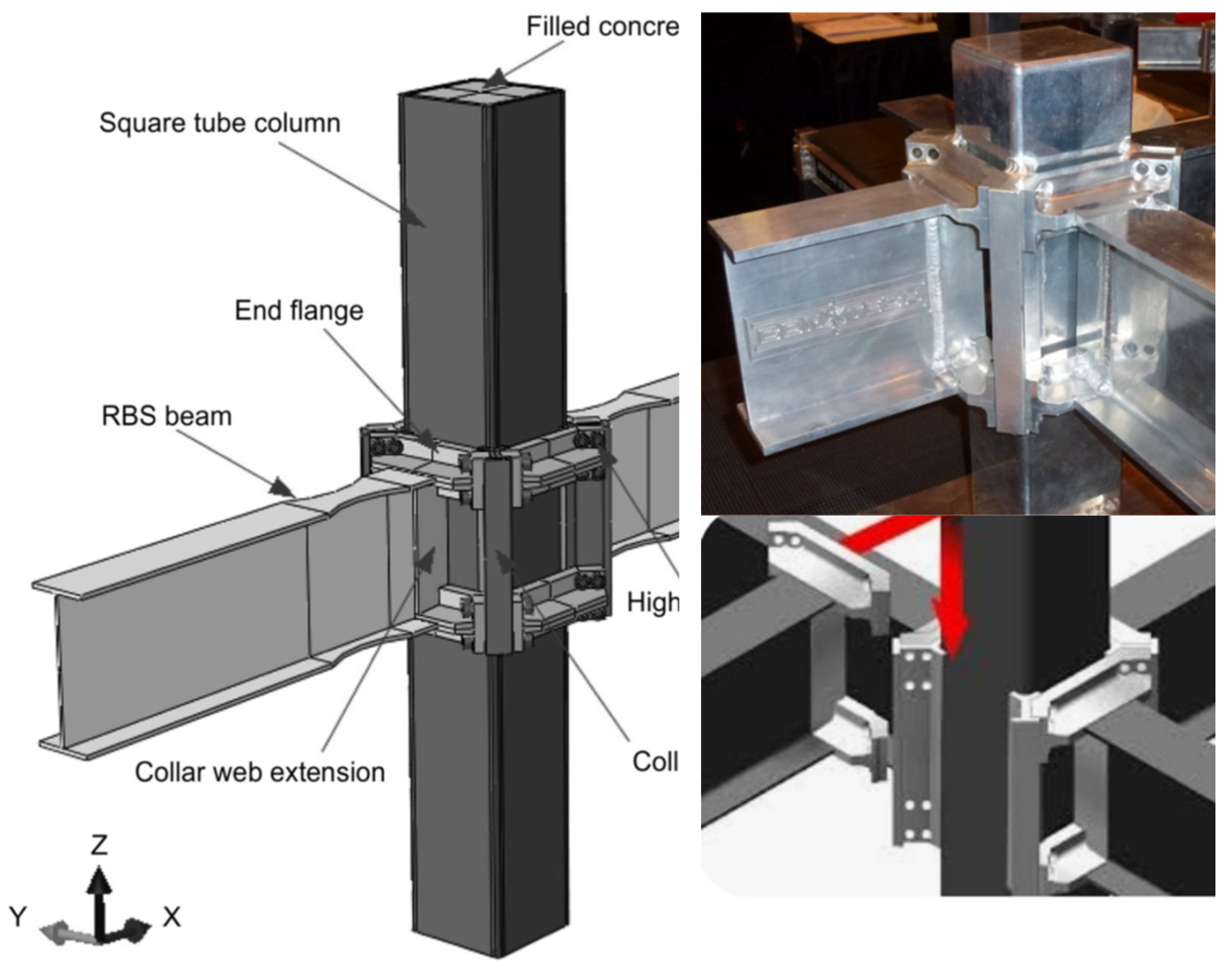
Figure 2.
Box-column with ConXL connection showing the attached collar corner assemblies’ details. Source: Figure elaborated by the authors.
Figure 2.
Box-column with ConXL connection showing the attached collar corner assemblies’ details. Source: Figure elaborated by the authors.
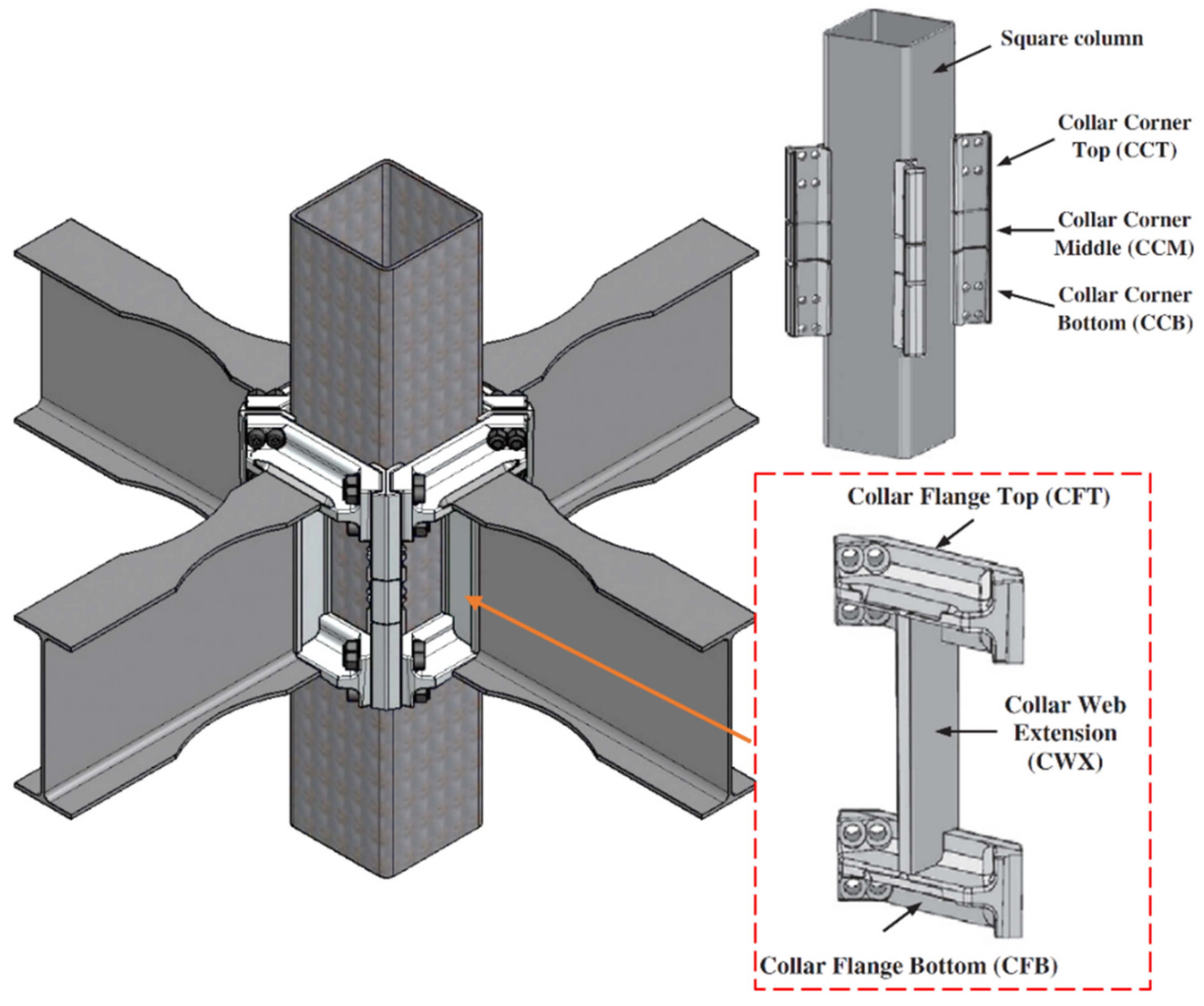
Figure 3.
Boundary conditions adopted on the initial FE model calibration.
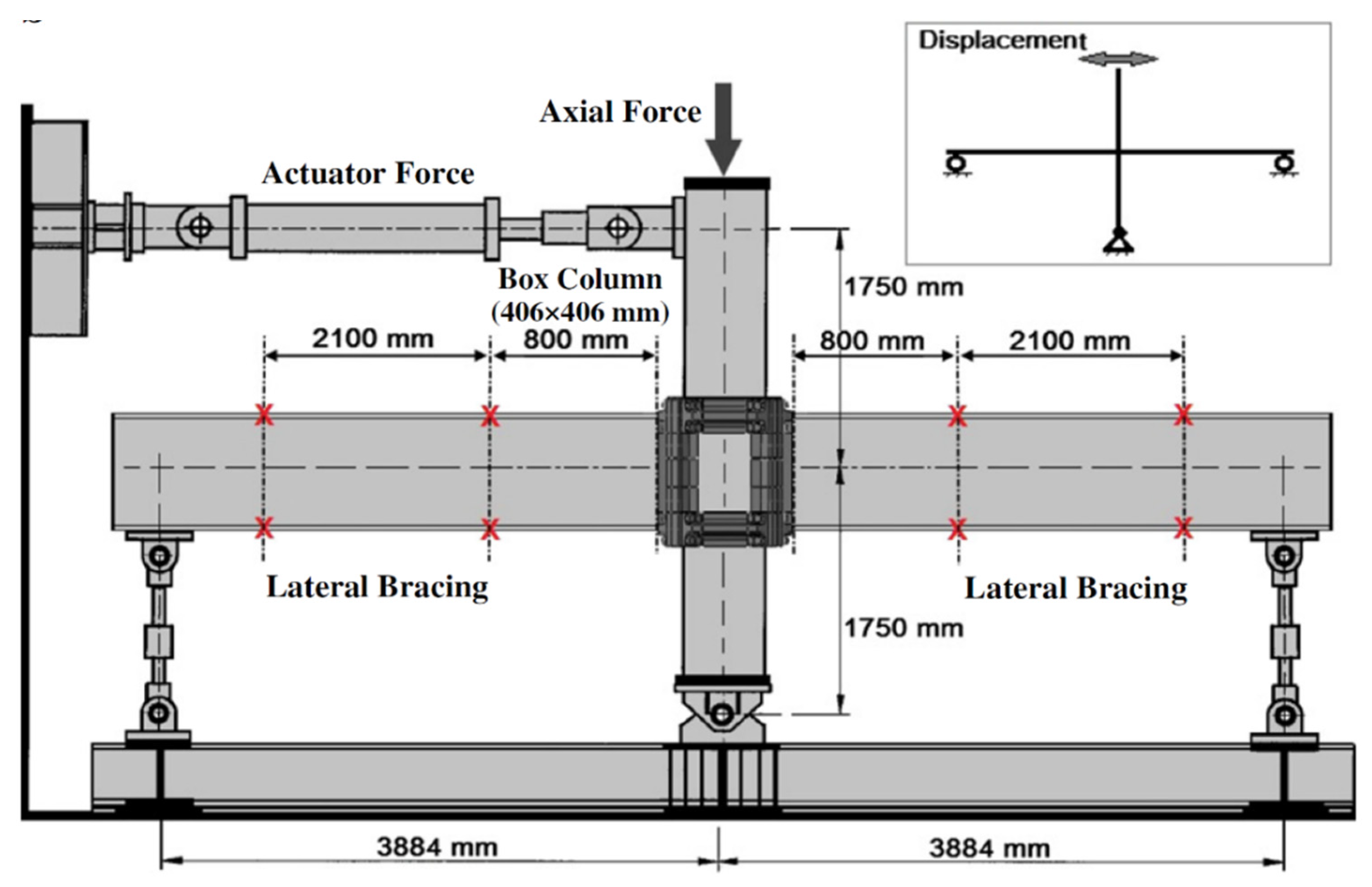
Figure 4.
Cyclic loading diagram based on ANSI/AISC 358-22 [33].
Figure 4.
Cyclic loading diagram based on ANSI/AISC 358-22 [33].
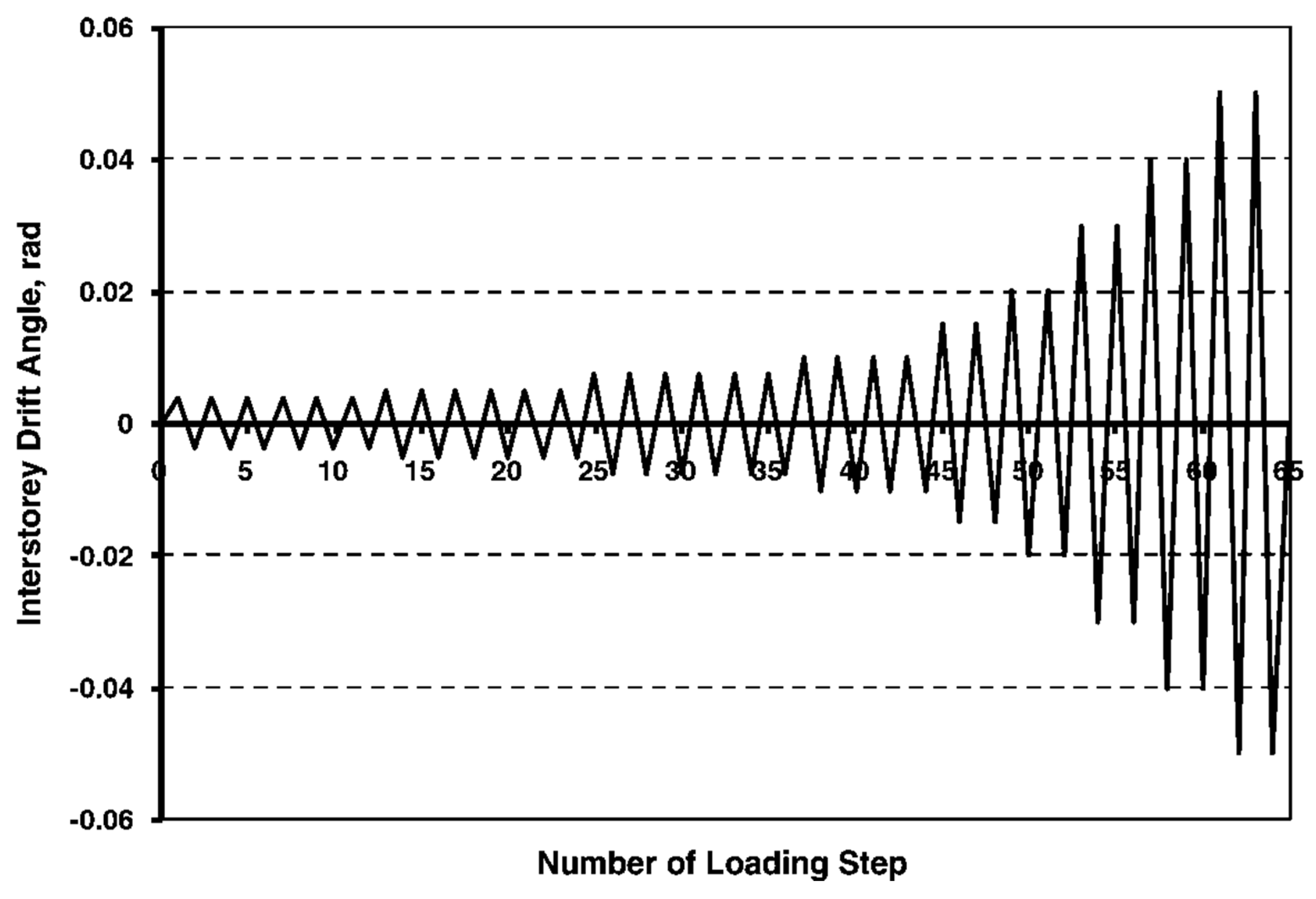
Figure 5.
The ISO standard fire curve and EC parametric fire curve applied to the FE models.
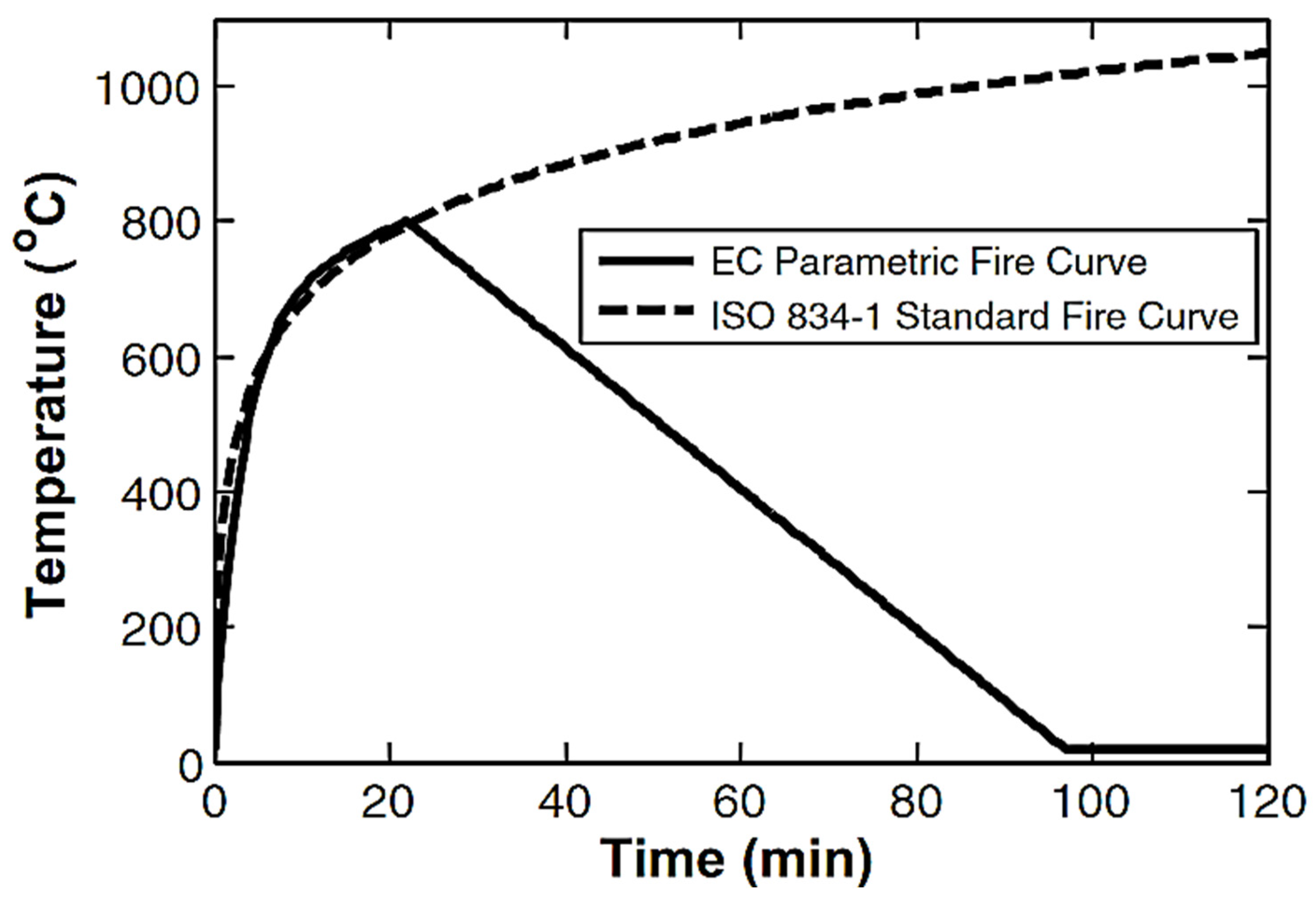
Figure 6.
Types of ConXL connections considered in the parametric study: (a) ConXL with RBS model C-R-NT, (b) ConXL without RBS model C-NR-NT, and (c) ConXL with T-sub model C-NR-T.
Figure 6.
Types of ConXL connections considered in the parametric study: (a) ConXL with RBS model C-R-NT, (b) ConXL without RBS model C-NR-NT, and (c) ConXL with T-sub model C-NR-T.
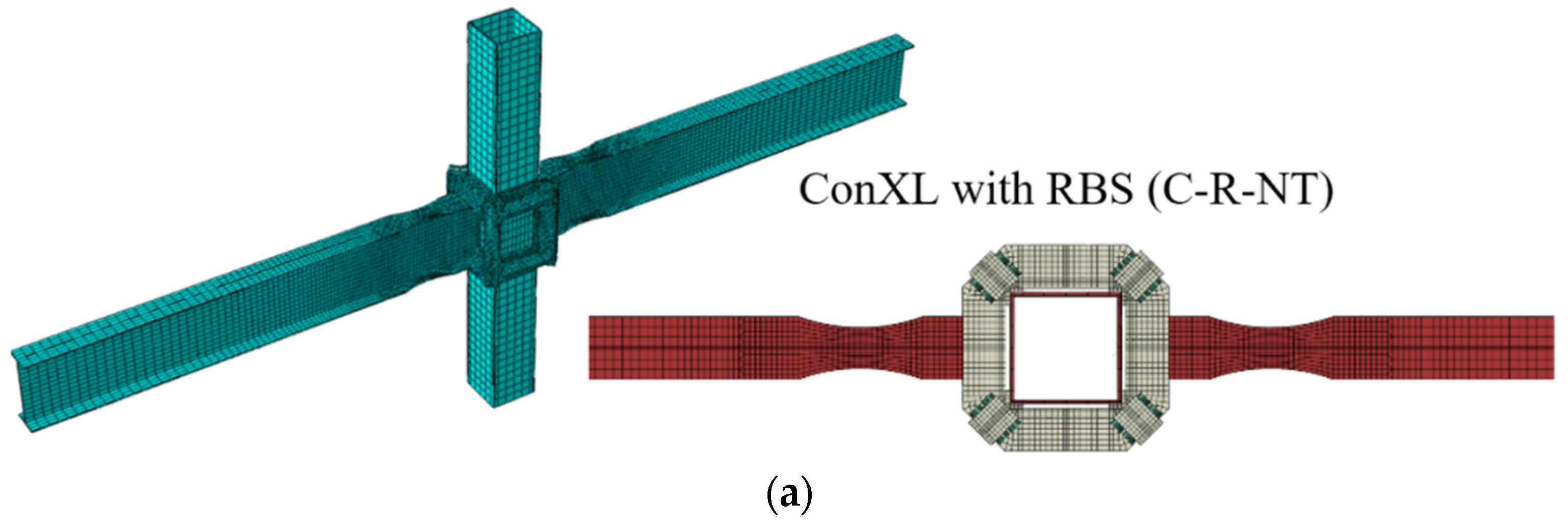
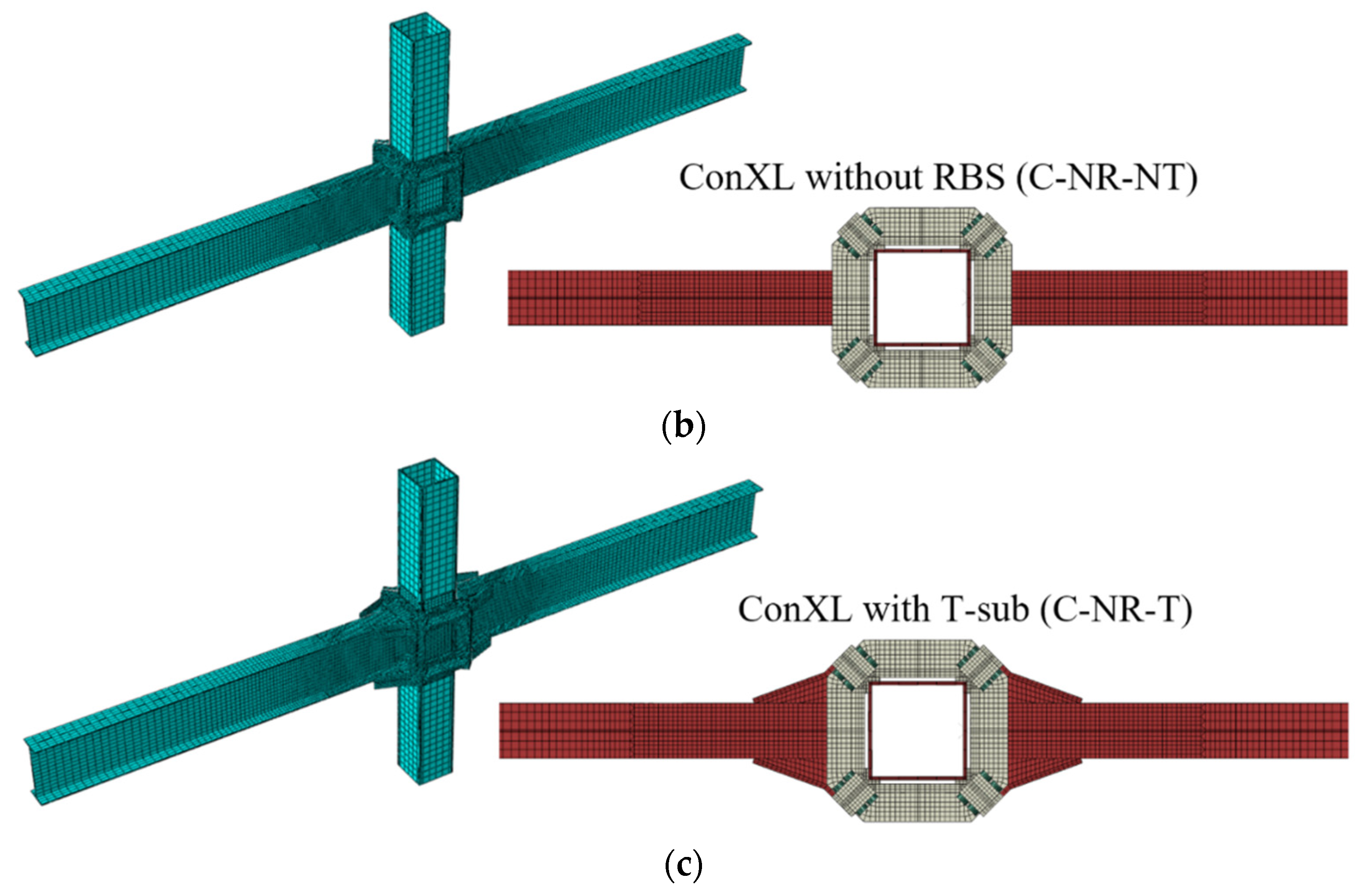
Figure 7.
Comparing the test results presented in [34] against the FE simulation results.
Figure 7.
Comparing the test results presented in [34] against the FE simulation results.
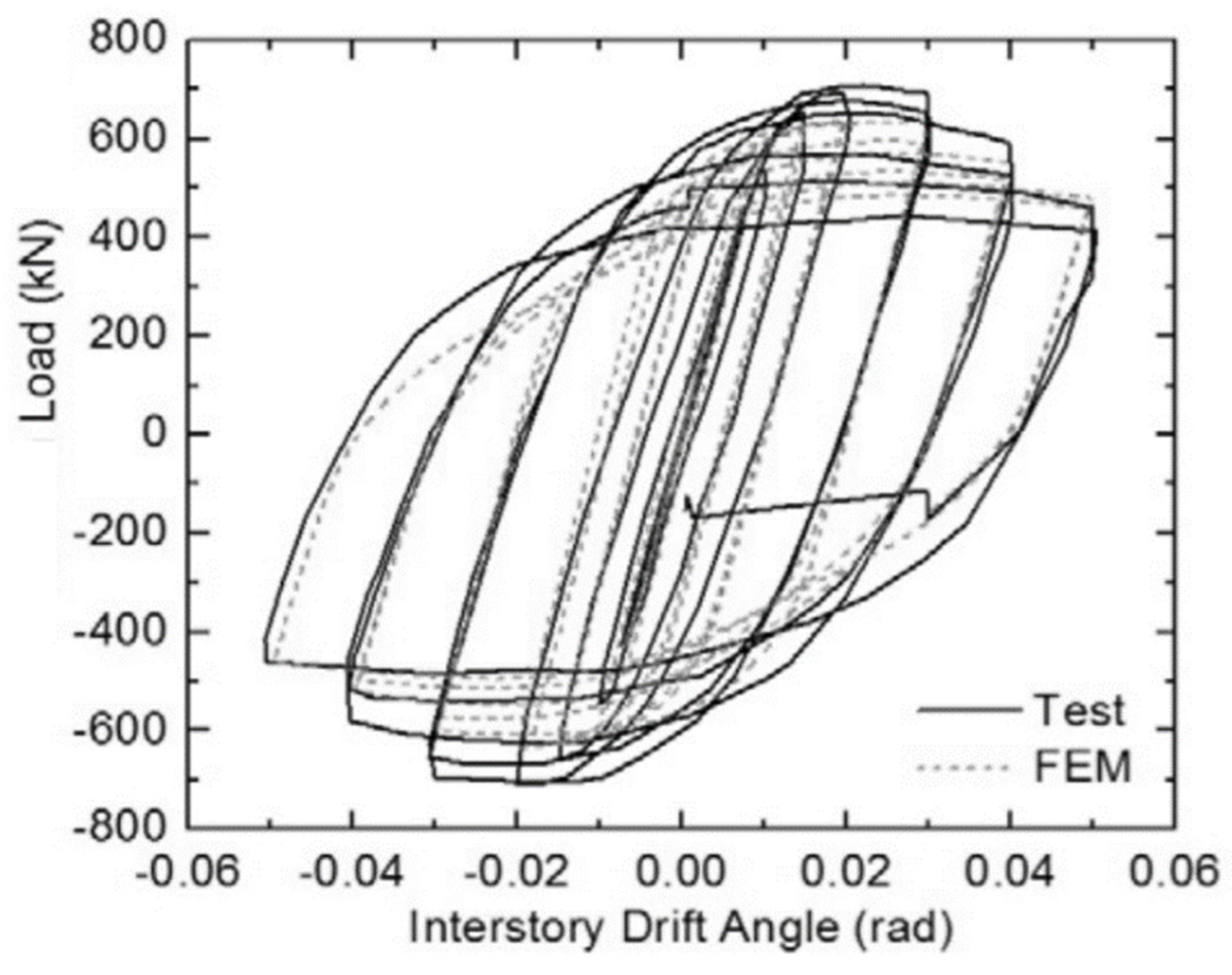
Figure 8.
Comparing the results considering the fire effect of: (a) models with T-stub C-NR-T and (b) models without T-stub C-NR-NT, and (c) models with RBS and without T-stub, C-R-NT.
Figure 8.
Comparing the results considering the fire effect of: (a) models with T-stub C-NR-T and (b) models without T-stub C-NR-NT, and (c) models with RBS and without T-stub, C-R-NT.
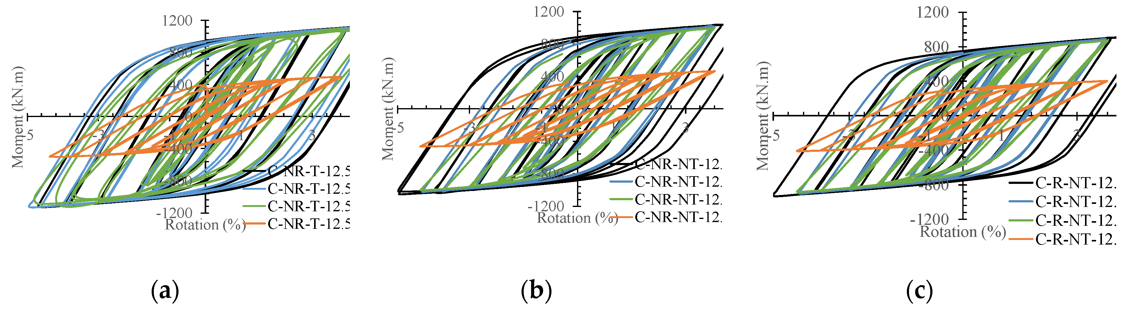
Figure 9.
The hinge formation of the elements for (a) C-R-NT model at Tu = 0 °C, (b) C-R-NT model at Tu = 6000 °C, (c) C-NR-NT model at Tu = 0 °C, (d) C-NR-NT model at Tu = 6000 °C, (e) C-NR-T model at Tu = 0 °C, and (f) C-NR-T model at Tu = 6000 °C.
Figure 9.
The hinge formation of the elements for (a) C-R-NT model at Tu = 0 °C, (b) C-R-NT model at Tu = 6000 °C, (c) C-NR-NT model at Tu = 0 °C, (d) C-NR-NT model at Tu = 6000 °C, (e) C-NR-T model at Tu = 0 °C, and (f) C-NR-T model at Tu = 6000 °C.
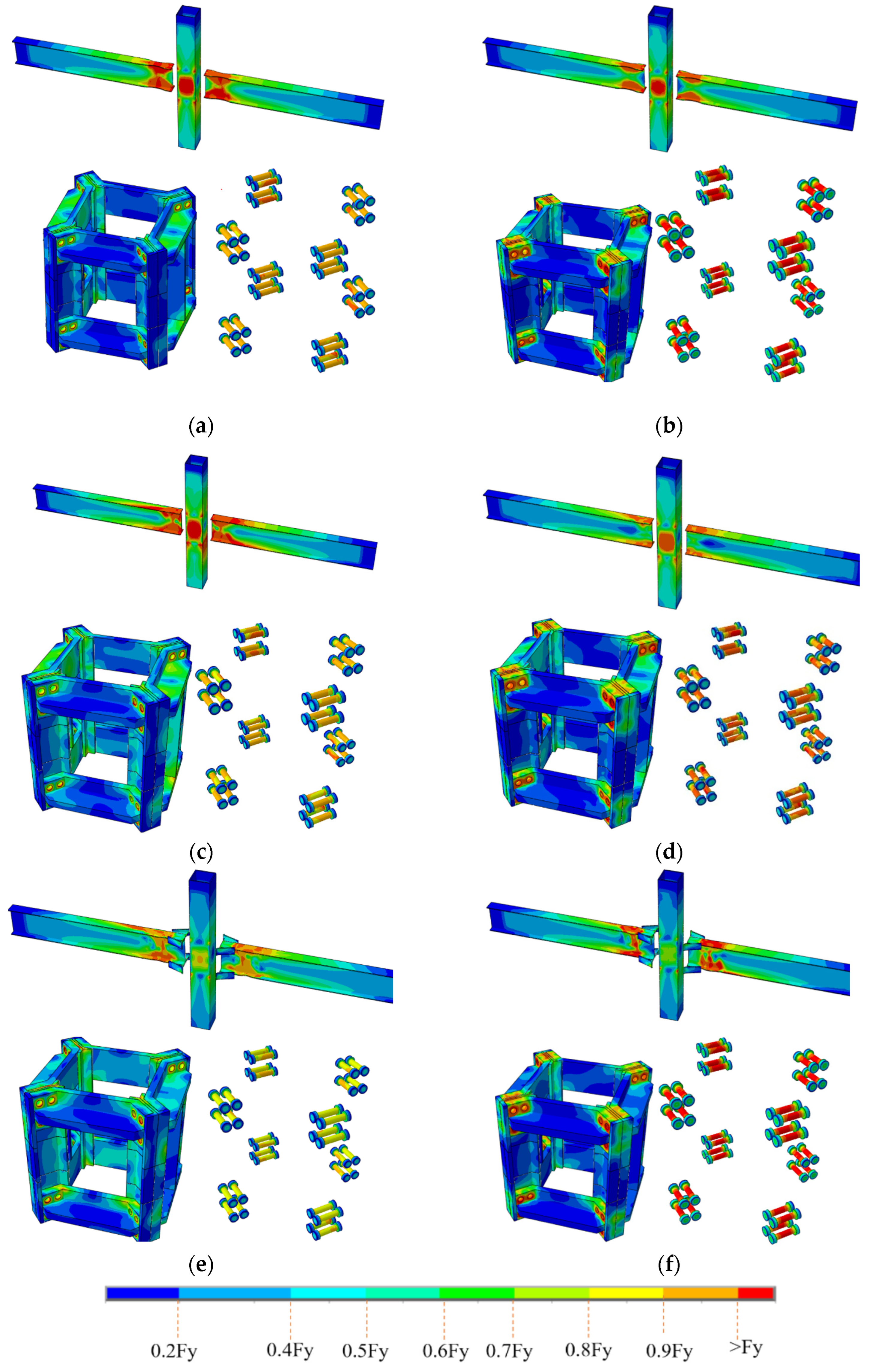
Figure 10.
ConXL connection hysteresis curves for: (a) C-NR-NT-12.5 model at Tu = 0 °C, (b) C-NR-T model at Tu = 0 °C, (c) comparing the models C-NR-NT-12.5 and C-NR-T at Tu = 0 °C (d) C-NR-NT-12.5 model at Tu = 200 °C, (e) C-NR-T model at Tu = 200 °C, (f) comparing the models C-NR-NT-12.5 and C-NR-T at Tu = 200 °C (g) C-NR-NT-12.5 model at Tu = 400 °C, (h) C-NR-T model at Tu = 400 °C, (i) comparing the models C-NR-NT-12.5 and C-NR-T at Tu = 400 °C (j) C-NR-NT-12.5 model at Tu = 600 °C, (k) C-NR-T model at Tu = 600 °C, (l) comparing the models C-NR-NT-12.5 and C-NR-T at Tu = 600 °C.
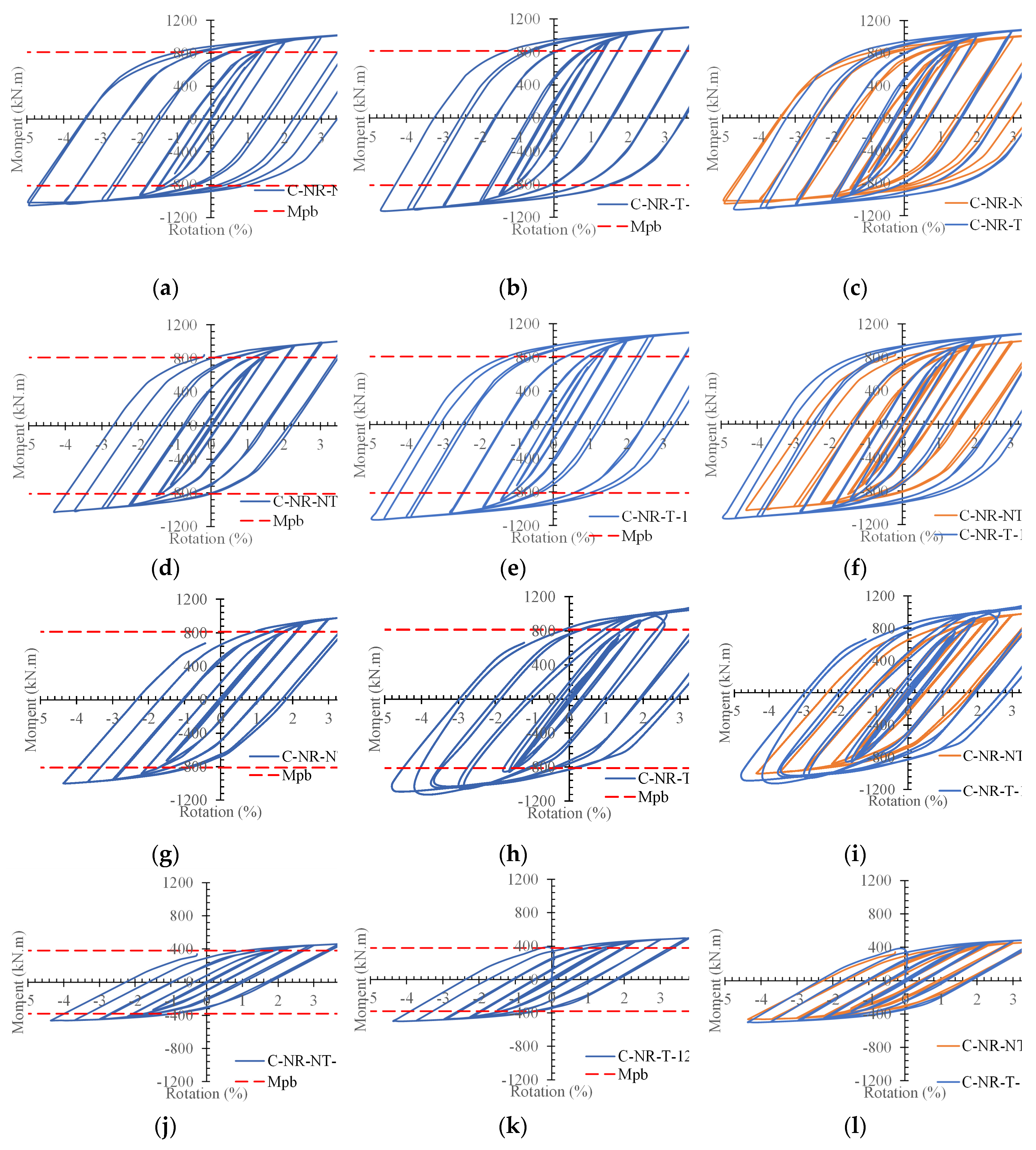
Figure 11.
Proposed equations to predict the capacity of the C-NR-T, C-NR-NT, and C-R-NT models.
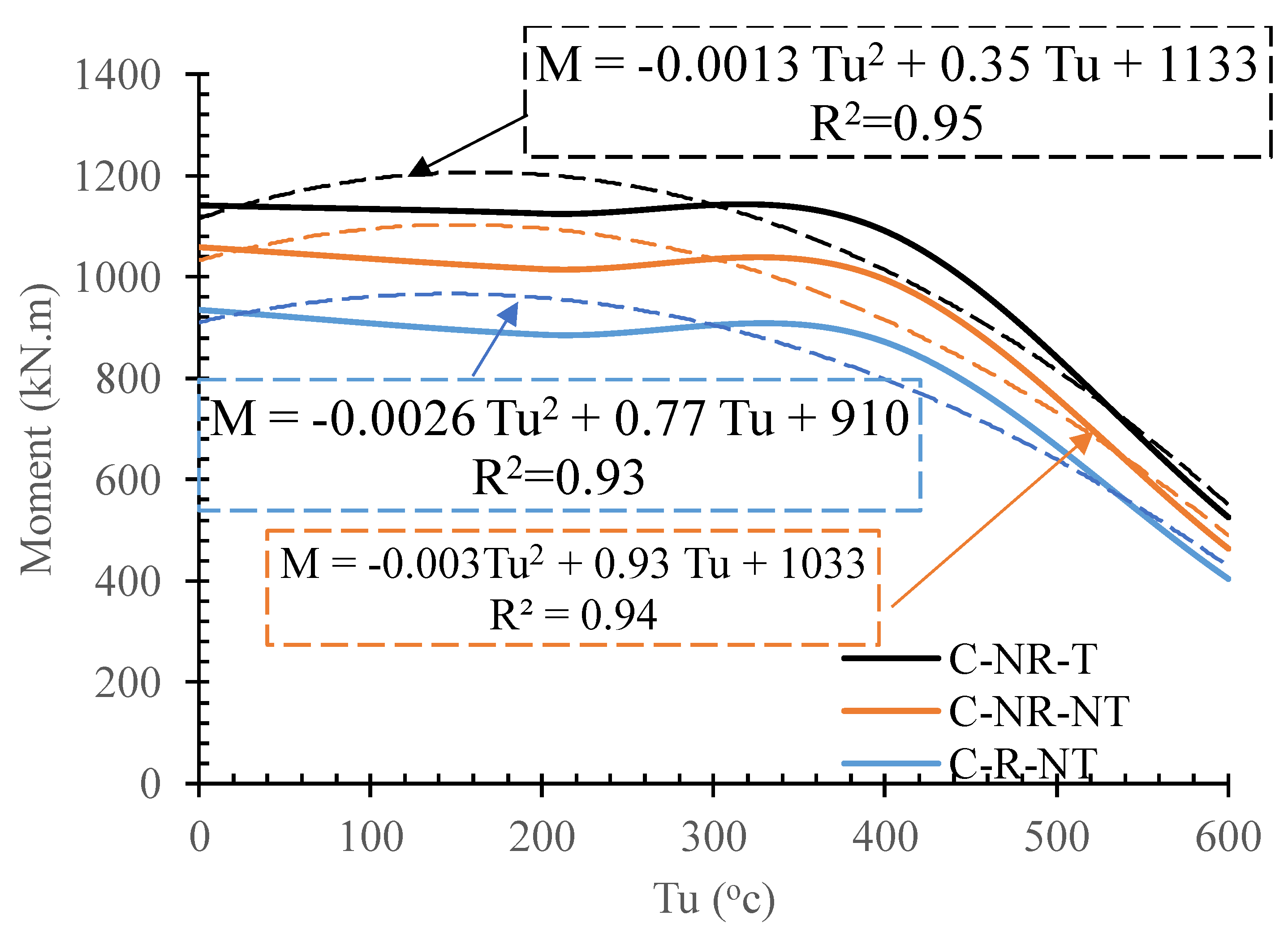
Figure 12.
Comparing the elastic stiffness of the C-NR-NT-12.5, C-NR-T-12.5, and C-R-NT-12.5 at (a) Tu = 0 °C, (b) Tu =20 0 °C, (c) Tu =40 0 °C, (d) Tu =60 0 °C.
Figure 12.
Comparing the elastic stiffness of the C-NR-NT-12.5, C-NR-T-12.5, and C-R-NT-12.5 at (a) Tu = 0 °C, (b) Tu =20 0 °C, (c) Tu =40 0 °C, (d) Tu =60 0 °C.
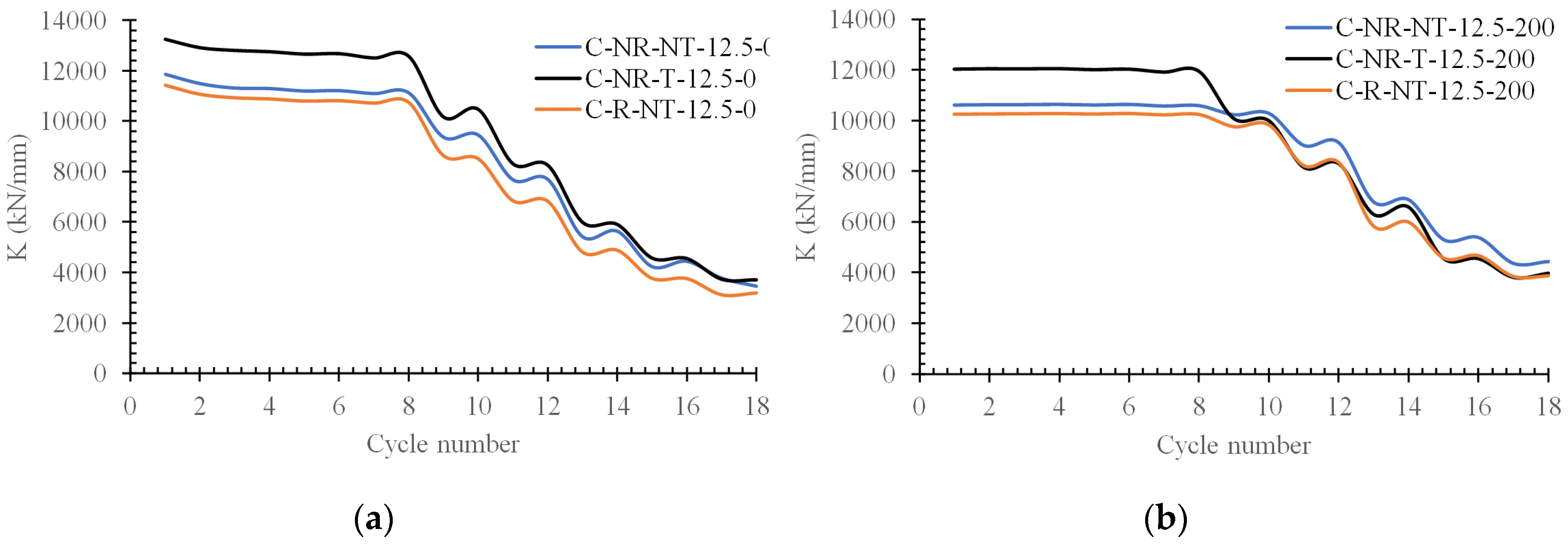
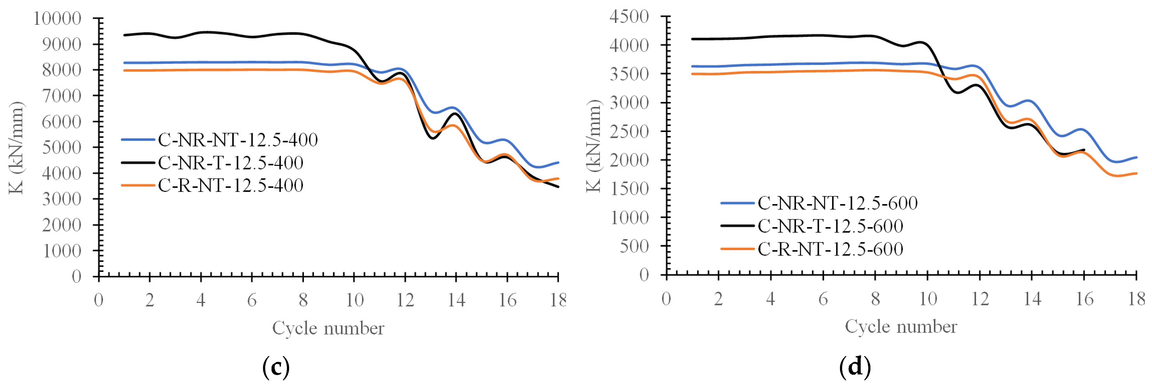
Figure 13.
Comparing the energy dissipation capacity of the models based on the different temperature scenarios explored.
Figure 13.
Comparing the energy dissipation capacity of the models based on the different temperature scenarios explored.
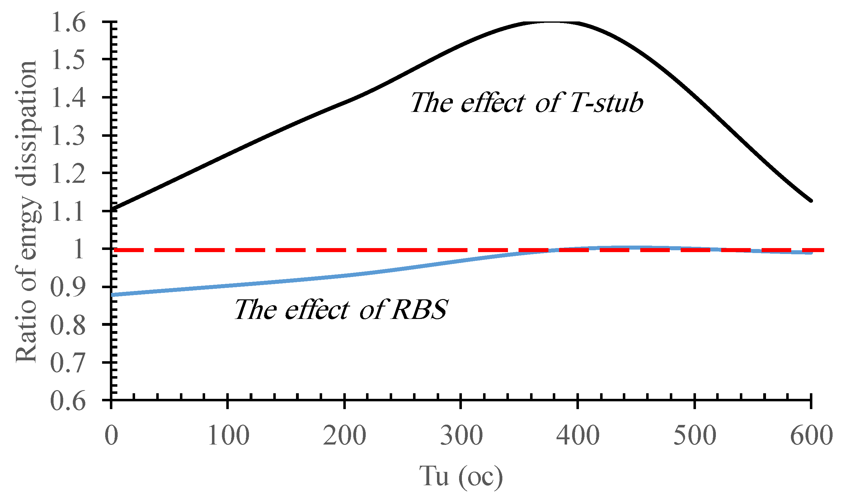
Figure 14.
Comparing the energy dissipation of the C-NR-NT-12.5, C-NR-T-12.5, and C-R-NT-12.5 at (a) Tu = 0 °C, (b) Tu =20 0 °C, (c) Tu =40 0 °C, (d) Tu =60 0 °C; and Comparing the accumulated energy ratio of the C-NR-NT-12.5, C-NR-T-12.5, and C-R-NT-12.5 at (e) Tu = 0 °C, (f) Tu =20 0 °C, (g) Tu =40 0 °C, (h) Tu =60 0 °C.
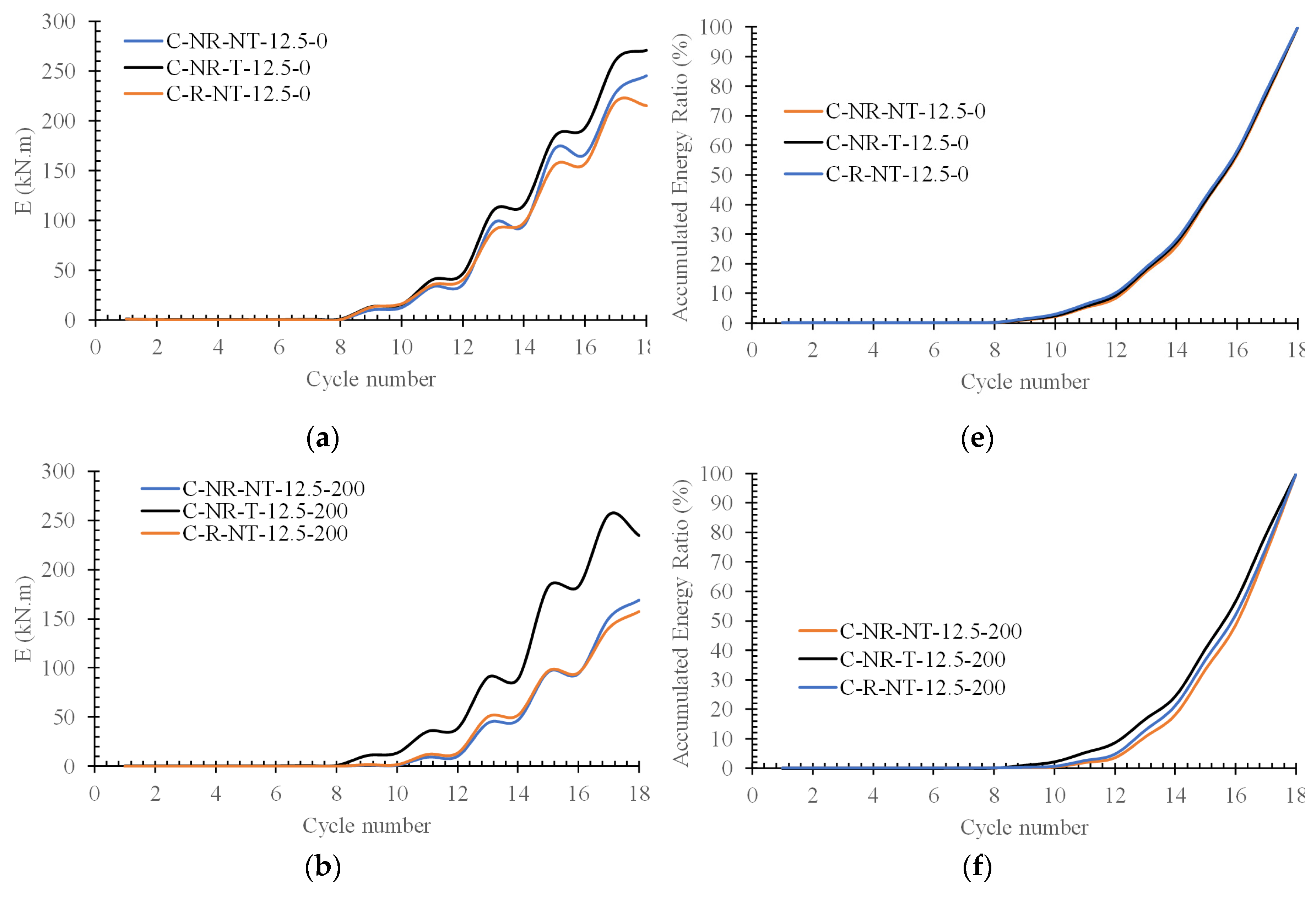
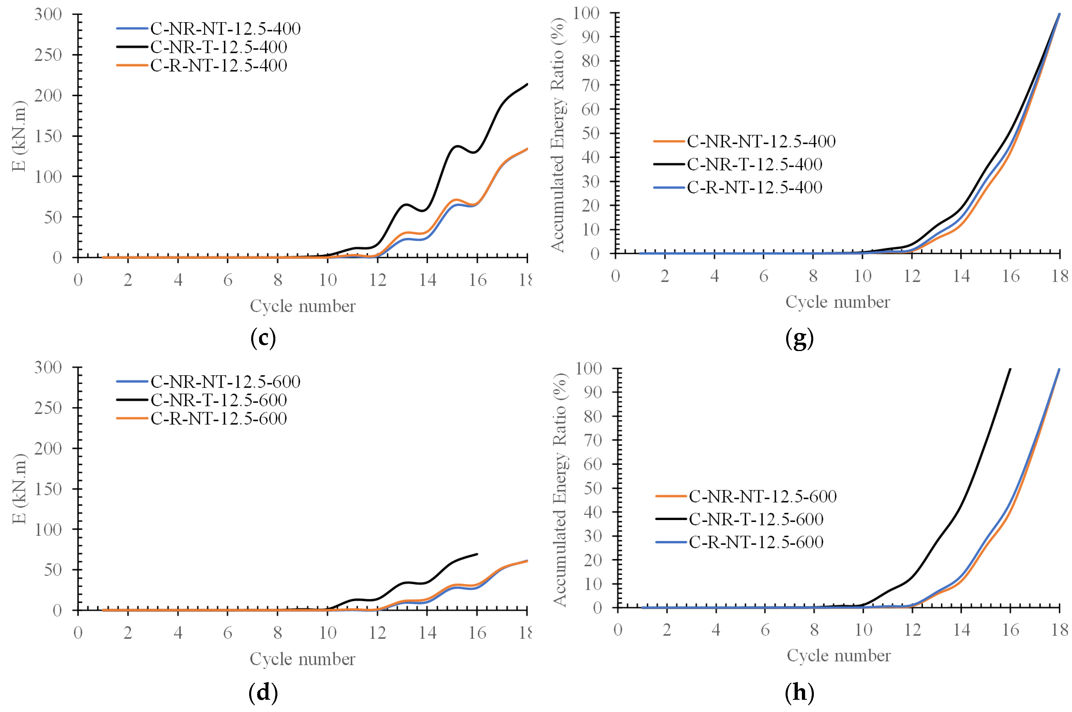

Table 1.
Comparing the ultimate strength of the models.
| Models | Pu (kN) | M (kN.m) | Tu = i/Tu = 0 | Model with T/ Model without T | Model with RBS/ Model without RBS |
|---|---|---|---|---|---|
| C-NR-T-12.5-0 | 652.33 | 1141.6 | 1.00 | 1.08 | |
| C-NR-T-12.5-200 | 643.00 | 1125.3 | 0.99 | 1.11 | |
| C-NR-T-12.5-400 | 623.23 | 1090.7 | 0.96 | 1.10 | |
| C-NR-T-12.5-600 | 495.59 | 867.28 | 0.76 | 1.87 | |
| C-NR-NT-12.5-0 | 605.45 | 1059.5 | 1.00 | ||
| C-NR-NT-12.5-200 | 580.70 | 1016.2 | 0.96 | ||
| C-NR-NT-12.5-400 | 568.60 | 995.05 | 0.94 | ||
| C-NR-NT-12.5-600 | 264.79 | 463.38 | 0.44 | ||
| C-R-NT-12.5-0 | 534.29 | 935 | 1.00 | 0.88 | |
| C-R-NT-12.5-200 | 506.37 | 886.15 | 0.95 | 0.87 | |
| C-R-NT-12.5-400 | 497.95 | 871.42 | 0.93 | 0.88 | |
| C-R-NT-12.5-600 | 231.32 | 404.81 | 0.43 | 0.87 |
Table 2.
Comparing the elastic stiffness of the models.
| Models | K | Tu = i/Tu = 0 | Model with T/ Model without T | Model with RBS/ Model without RBS |
|---|---|---|---|---|
| C-NR-T-12.5-0 | 13256 | 1.00 | 1.12 | |
| C-NR-T-12.5-200 | 12034 | 0.91 | 1.13 | |
| C-NR-T-12.5-400 | 9337.8 | 0.70 | 1.13 | |
| C-NR-T-12.5-600 | 4102.0 | 0.31 | 1.13 | |
| C-NR-NT-12.5-0 | 11850 | 1.00 | ||
| C-NR-NT-12.5-200 | 10621 | 0.90 | ||
| C-NR-NT-12.5-400 | 8266.5 | 0.70 | ||
| C-NR-NT-12.5-600 | 3630.5 | 0.31 | ||
| C-R-NT-12.5-0 | 11435 | 1.00 | 0.96 | |
| C-R-NT-12.5-200 | 10246 | 0.90 | 0.96 | |
| C-R-NT-12.5-400 | 7972.8 | 0.70 | 0.96 | |
| C-R-NT-12.5-600 | 3498.1 | 0.31 | 0.96 |
Table 3.
Comparing the energy dissipation of the models.
| Models | E | Tu = i/Tu = 0 | Model with T/ Model without T | Model with RBS/ Model without RBS |
|---|---|---|---|---|
| C-NR-T-12.5-0 | 270.78 | 1.00 | 1.10 | |
| C-NR-T-12.5-200 | 234.42 | 0.87 | 1.39 | |
| C-NR-T-12.5-400 | 213.99 | 0.79 | 1.60 | |
| C-NR-T-12.5-600 | 69.20 | 0.26 | 1.13 | |
| C-NR-NT-12.5-0 | 245.25 | 1.00 | ||
| C-NR-NT-12.5-200 | 169.14 | 0.69 | ||
| C-NR-NT-12.5-400 | 134.14 | 0.55 | ||
| C-NR-NT-12.5-600 | 61.37 | 0.25 | ||
| C-R-NT-12.5-0 | 215.51 | 1.00 | 0.88 | |
| C-R-NT-12.5-200 | 157.23 | 0.73 | 0.93 | |
| C-R-NT-12.5-400 | 134.18 | 0.62 | 1.00 | |
| C-R-NT-12.5-600 | 60.78 | 0.28 | 0.99 |
Disclaimer/Publisher’s Note: The statements, opinions and data contained in all publications are solely those of the individual author(s) and contributor(s) and not of MDPI and/or the editor(s). MDPI and/or the editor(s) disclaim responsibility for any injury to people or property resulting from any ideas, methods, instructions or products referred to in the content. |
© 2024 by the authors. Licensee MDPI, Basel, Switzerland. This article is an open access article distributed under the terms and conditions of the Creative Commons Attribution (CC BY) license (http://creativecommons.org/licenses/by/4.0/).
Copyright: This open access article is published under a Creative Commons CC BY 4.0 license, which permit the free download, distribution, and reuse, provided that the author and preprint are cited in any reuse.


