1. Introduction
Throughout history, human progress has sought to improve well-being, including health, safety and comfort. This has been achieved through several advances in everyday devices and the use of various accessible natural resources. For many years, electromagnetic (EM) energy has occupied an important place, increasing over time. This energy has been obtained from the conversion of different resources, usually fossil constituents. Recently, well-being in an ecological context has been associated with biodiversity and the ecosystem. This can be achieved by using clean resources for conversion into EM energy, managing the storage of this energy and eco-designing EM devices; this corresponds to a sustainable use of energy inputs and outputs. Thus, the performance of tools is improved, energy is saved through its eco-use and intelligent storage management, and the likely side effects of EM tools on the biodiversity environment and the ecosystem are reduced; these elements correspond to the Responsible Attitude (RA) approach.
In a context of smart eco-urbanism, the RA approach, via the reduction of the side effects of EM fields (EMF), is associated with the general health of living tissues involved in urban biodiversity. Indeed, EM tools aim at useful objectives (for human well-being) that are generally associated with unsolicited effects linked to parasitic EMFs. These fields can directly disturb the living tissues of biodiversity by producing harmful biological effects (BE), or indirectly by disrupting the functioning of devices associated with the tissues. The interdependent articulation of the different members of biodiversity, materializes the fact that EM tools built by man would produce, in addition to the projected objectives, negative effects for humans as well as for biodiversity and the ecosystem. Thus, such health interdependence corresponds to the concept or approach One Health (OH) [
1,
2].
The abovementioned disorders triggered by EMF exposure can be caused by wireless communication devices, e.g. [
3], mobility devices, e.g. [
4], or wireless power transfer devices [
5,
6] commonly used in daily life. Different types of exposures are correlated to the tools concerning the wireless transfer or transmission of EM energy. These categories concern the range of the transfer, the transferred power, the frequency of the EMF, and the character of the exposed object as well as its location. Wireless inductive power transfer (IPT) covers a wide power range, from a few watts for small household tools [
7,
8] to a few kilowatts for electric vehicles (EVs), including cars, buses, trucks, boats, etc. [
9,
10]. The transfer distance is relatively small (a few mm to a few cm). The frequency of EMFs is 50 Hz for small household tools, and 85 kHz (as standard but can reach 200 kHz in specific cases) for EVs. Possible EM disturbances could concern objects located at a distance of a few cm for small tools, up to about one meter for IPTs aboard EVs.
Energy storage by EV batteries is a decisive point of an ecologically responsible transport. This storage is strongly linked not only to the type of internal composition of the battery, but also to different external managements related to its capacity status [
11,
12,
13]. The charging strategy of IPTs in EVs is closely linked to the state of the energy storage (battery cells), the complexity of the infrastructure, the EV autonomy and the safety concerns regarding biodiversity and the urban ecosystem. In the context of smart urban planning, these strategic elements could be taken into account in an RA approach associated with motoring arrangement e.g. [
14] and connected smart monitoring organization [
15,
16,
17,
18,
19] based for example on the concept of digital twins (DT) [
20,
21,
22,
23,
24,
25,
26,
27].
The present contribution aims to analyze and evaluate different approaches or concepts, namely RA, OH and DT, involved in the management of EM energy storage of EVs interconnected to the public grid in a smart urban environment. Such management includes optimized performance of the IPT charging tool with minimized adverse effects as well as an optimized charging mode strategy for each specific situation of the EV. The following sections of the paper will analyze and illustrate this management. These involve: an overview of electric vehicles in smart mobility / sustainable design and control / governance of physical phenomena and mathematical equations / EMF exposure in relation to charging routines and protection / an example of urban bus charging mode analysis / an example of BE exposure in a human body in the vicinity of an EV / supervision of a complex connected vehicle, a smart environment and the grid / a discussion on further details of the notions and concepts involved in the developed analyses. Each topic covered in this article, although stand-alone, is supported by examples from the literature to allow for a deeper understanding.
2. Overview of EVs in Smart Mobility
A typical example of the use of decarbonized energy in transport is related to the replacement of internal combustion engines with EVs equipped with energy storage batteries. This strategy was reasoned in an ecological context to reduce pollution, thus preserving biodiversity and the ecosystem. When replacing a traditional mode of transport to preserve biodiversity and the ecosystem, it is mandatory to ensure that the substitution strategy is consistent with this safeguard.
2.1. Energy Transfer and Storage
Smart mobility is therefore in fact linked to the use of EVs in an ecological context. This mobility includes different types of traffic such as urban, road, maritime traffic, etc. and different categories of vehicles for specific uses. For example, urban or road cars, buses, trucks, etc., private or public transport including taxis, urban buses, etc. and short or long distance transport including trains, ships and planes. The smart management of these situations is different and depends on the transport context related to passengers, goods, raw materials, healthcare, security, etc. The electrical energy required for EV operation comes from the public grid via energy storage batteries aboard the vehicle. This energy transfer could be achieved by cables via chargers involving controlled AC/DC converters aboard vehicle or wirelessly by means of IPTs (see the next section for their construction). Following the evolution of intelligence, EV storage batteries will eventually be supported wirelessly by IPTs entirely in both charging modes, stationary and running. Moreover, the construction of these IPTs must promote optimal ecology associated with clean energy use and frugality. In such a context, both RA and OH approaches would fulfill their role in the design and management of IPT devices.
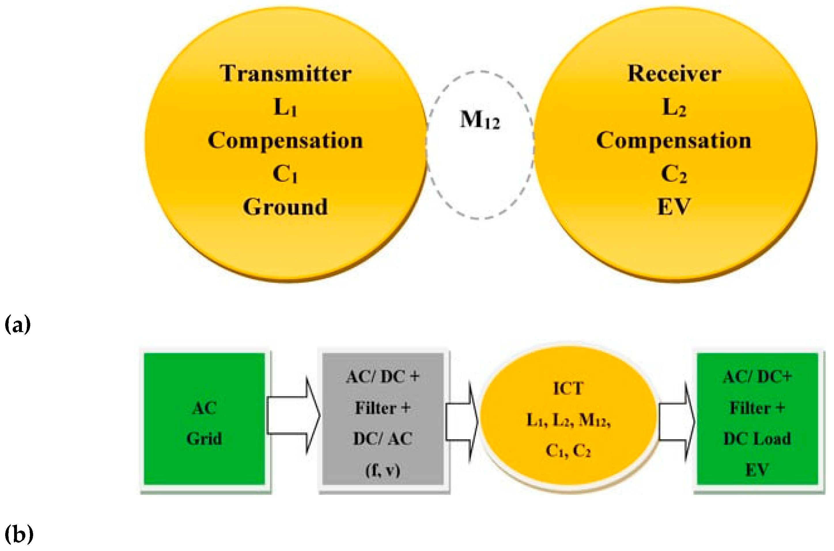
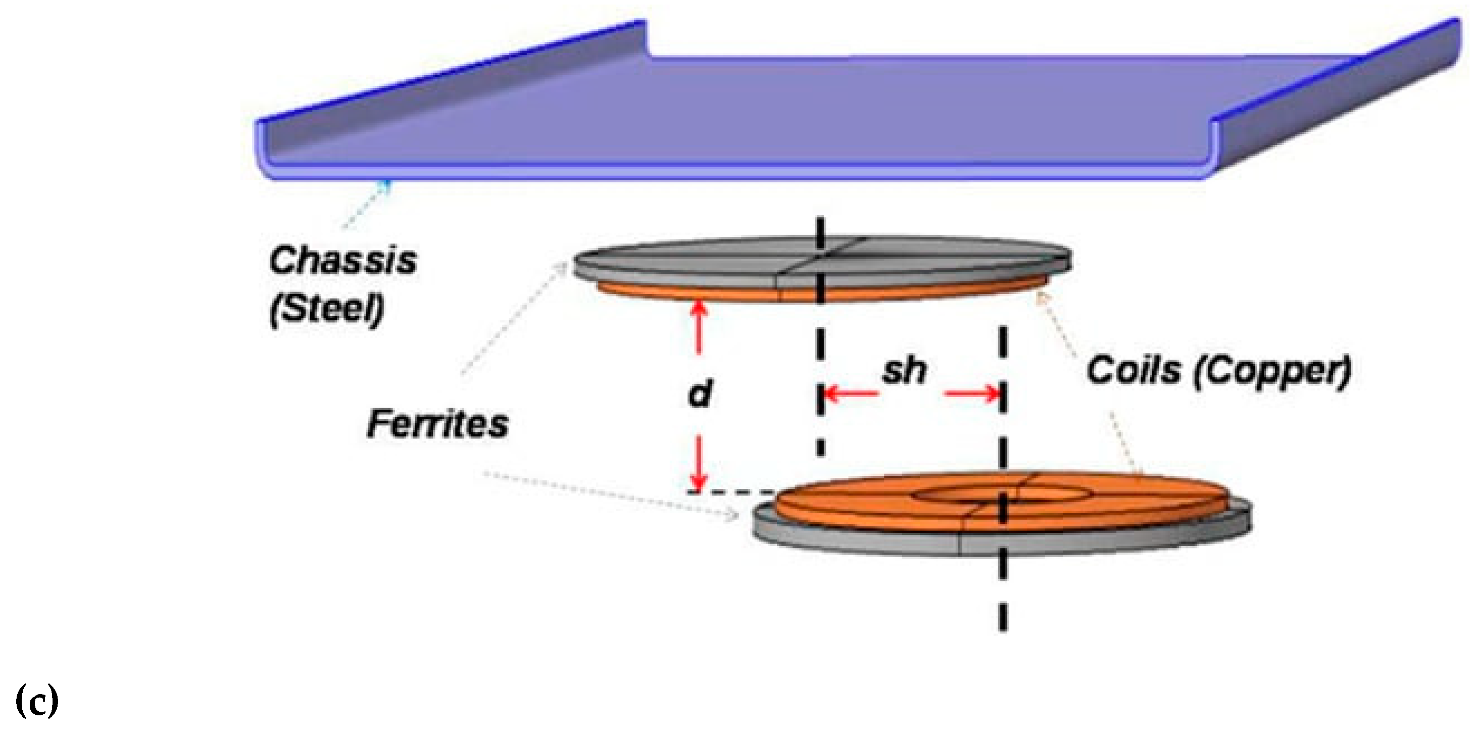
2.2. Wireless IPT Constituents
A wireless IPT in EV is embraced between the power grid and the energy storage battery. The IPT midway component accountable for wireless action is an inductive coupler transformer (ICT) linked to the grid and storage battery across static converters. The ICT is formed of two coils, transmitter and receiver, possessing inductances of L
1 and L
2, and separated by an airgap typifying a mutual inductance of M
12. The airgap magnitude exhibits a weak coupling of coils and therefore the required power transfer entails an important reactive power engagement. Thus, the coils are compensated by two capacities of C
1 and C
2. Accordingly, an IPT can achieve, a galvanic separated power transfer, with a capacitive compensation of electronics connected to ICT allowing their functioning at resonance. Such compensations guarantee reliable efficiency [
28,
29,
30,
31,
32,
33,
34,
35,
36] and can exploit different connection topologies (series or parallel) subject to different factors including the character of the storage battery, for instance the two sides topologies would be, SS, SP, PS, PP, etc. [
29,
36]. In the case of EV, the SS compensation topology appears to be a reliable choice [
35,
36]. To improve the transfer efficiency corresponding to a better coupling of the ICT coils, magnetic ferrite sheets are generally used to cover these coils.
Figure 1 shows representations of an IPT including its ICT details. The IPT embraces its ICT with ferrite sheets inserted between the power grid, through an AC-DC-AC filtered adjustable frequency-voltage conversion, and the storage battery, through an AC-DC filtered conversion [
19].
The ICT structure, sketched in
Figure 1a, is described in
Figure 1c. It comprises the two ICT coils, ground-transmitter, and EV bottom-receiver, along with the two magnetic ferrite plates coating the coils. Besides,
Figure 1c includes a steel plate representing the EV chassis. The coils of the ICT with their ferrites (pads) are separated by an air gap of distance (d) and coil axes shift (sh).
3. Sustainable Design of EV-IPT in Smart Mobility
As mentioned before, the RA approach contains the sustainable design of the IPT as well as the supervision of the energy storage and its IPT implementation. We review in this section the contributions of the RA and OH approaches in the sustainable design of the IPT components. The supervision of the IPT with the storage battery as a part of RA via the DT concept will be discussed in
Section 6.
The sustainable design of the IPT involves the construction of its components, including the ICT, the compensation scheme, the static converters and the filters (see
Figure 1). Such a design allows for enhanced performance [
28,
29,
30,
31,
32,
33,
34,
35,
36,
37,
38] involving better ICT coupling and reduced stray fields [
19,
39,
40], which illustrate the junction of the RA and OH approaches in the IPT design. Moreover, these two approaches are closely related to the state of charge and battery management [
41]. Energy storage management involves supervision of battery charging scheduling that supports sustainability associated with decarbonized and reasonably priced energy use [
42,
43]. In fact, EM energy is considered strictly clean if it comes from decarbonized conversion resources [
44].
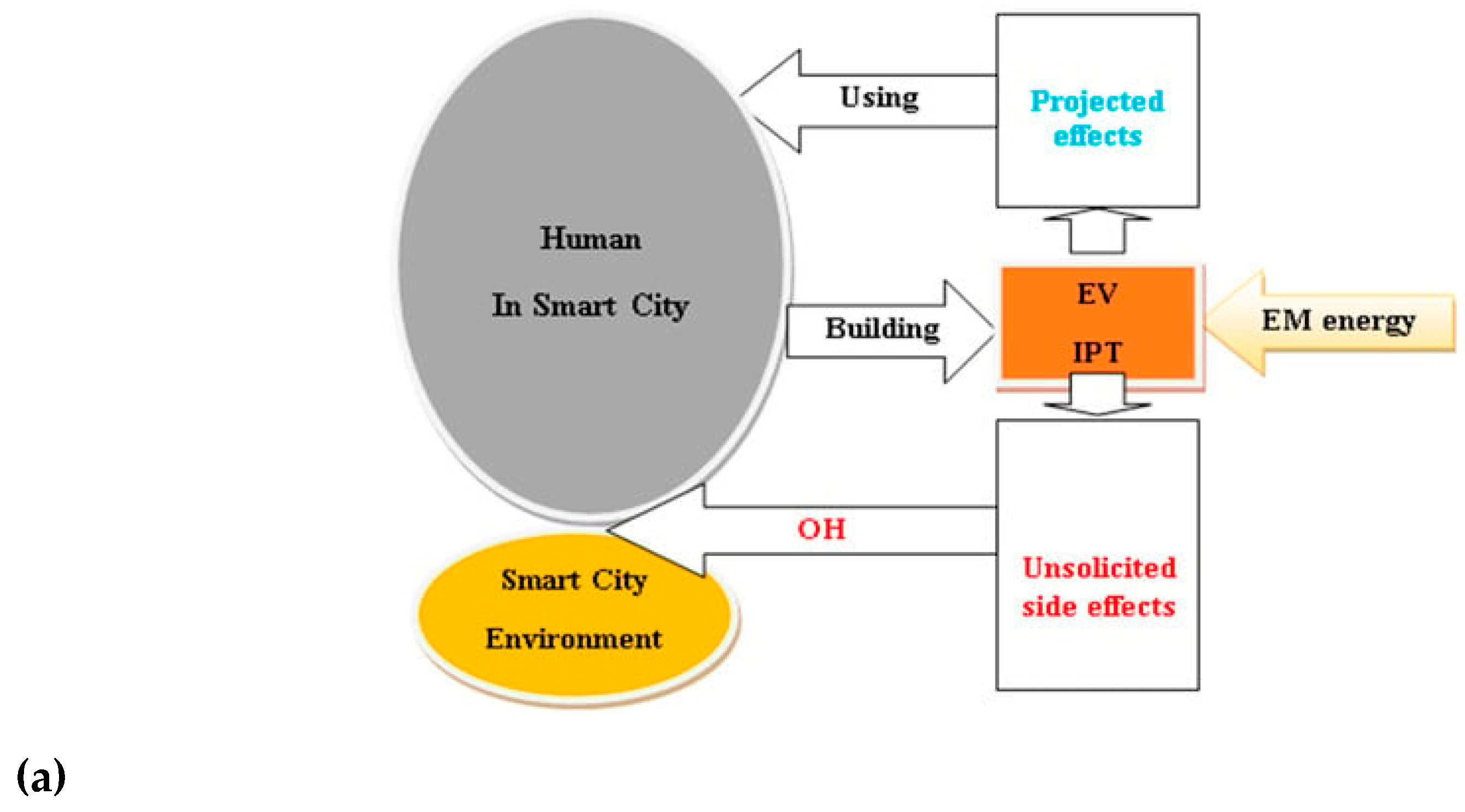
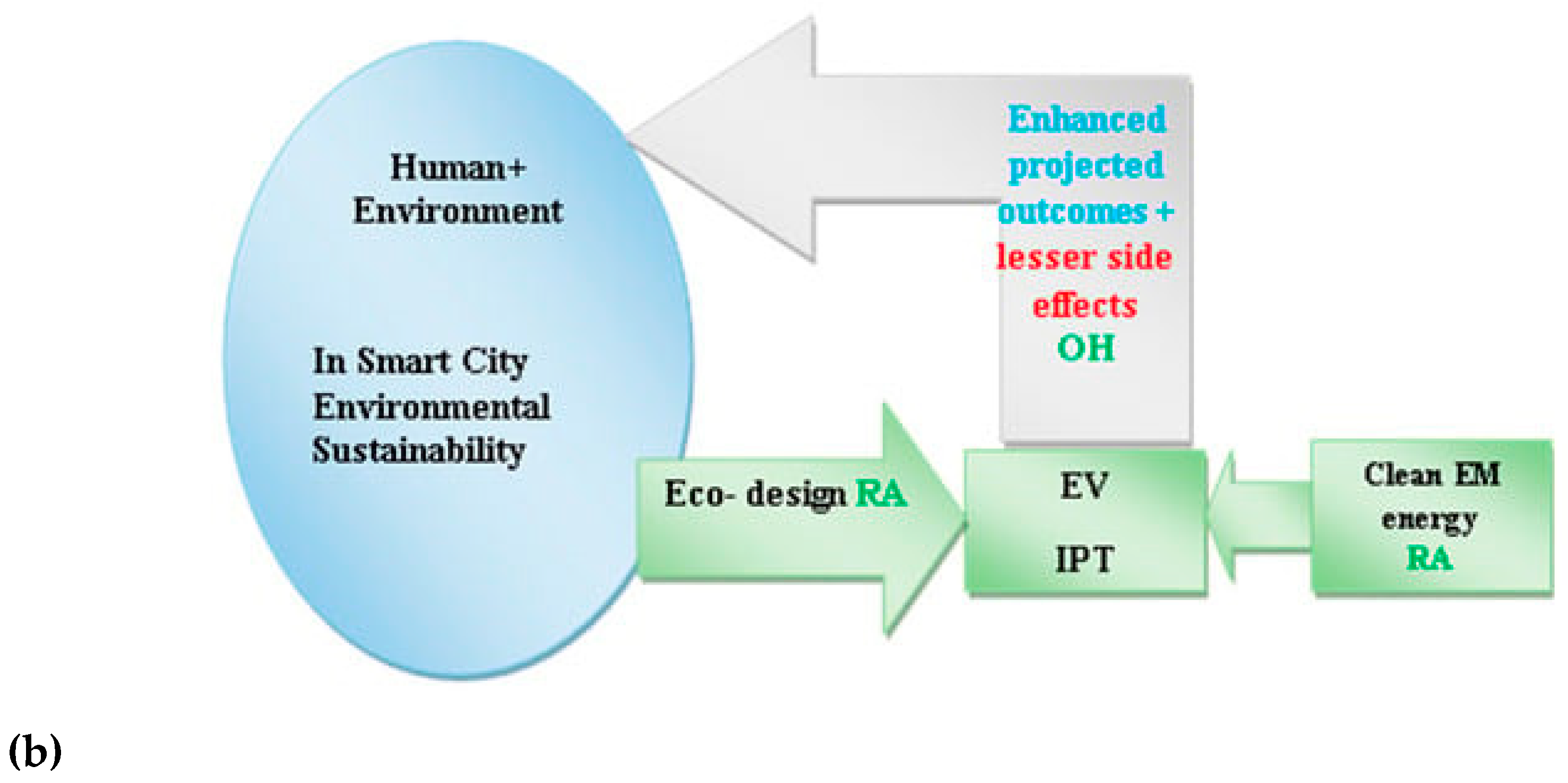
Figure 2 illustrates the two cases of unsustainable (a) and sustainable (b) design of an IPT in the urban context of smart cities (SC) [
19].
3.1. Charging Modes in Urban Smart Mobility Context
Smart urban mobility using EVs with battery charging by wireless IPTs is suitable for different categories of vehicles. These include shared and autonomous EVs, public buses, trams, shipping vessels, small delivery trucks, etc. The charging modes of IPTs involved in a smart urban environment can be mainly full static, full dynamic, mixed or distant static charging points. A full static mode corresponds to a restricted range and requires a large battery storage. The full dynamic case (electric roads) corresponds in general to a given urban trajectory, requires little battery storage (for discontinuous electric roads) and is used for public transport such as electric buses and trams. A mixed static-dynamic mode is mainly suitable for highways and requires medium battery storage. The distant static charging mode concerns public electric buses charging at specific trajectory stops for which the energy storage depends on the number of charging points and the static duration (see next section). Each of these charging modes requires specific protection against EMF exposure.
3.2. Case of an Urban Bus Charging Modes
In general, in the wireless charging of EV storage batteries, the relationship between storage capacity and vehicle range is theoretically organized as follows: neglecting the losses in the IPT-compensated coils, the transferred energy = the capacity of the energy storage batteries = the energy range of the vehicle, so Pt . Tt = nc . Cc = Pm . Tr . Pt and Tt are the transferred power and charging time, nc and Cc are the cells number of the battery and cell energy storage capacity, Pm and Tr are the power of the EV motor and its functioning time. Thus, as a first approximation, for a given transferred power, engine power and battery cell capacity, the charging time and operating autonomy time are correlated to the number of cells.
Taking the example of an analysis of the charging modes of a public-urban bus, the RA-OH selection of an IPT charging routine must take into account not only the energy storage capacity, but also the complexity of the charging infrastructure and the risk of exposure to radiated EMFs of the living tissues concerned in the urban biodiversity. In fact, the bus makes a given number of round trips (circuits) Nc per day. A circuit corresponds to a round trip trajectory between two ends. Each outward or return trajectory includes a given number of stops between its two ends Ns. Charging routines can be practiced at different levels, namely day, circuit, single trajectory or stops; this order corresponds to decreasing storage capacities associated with a corresponding decreasing operating autonomy. These IPT charging routines involve different infrastructure complexities and risks of exposure to stray EMFs. Both of these factors have a significant impact on the choice of charging routine. The most important decision elements are the costs of infrastructure and safety protection shields, as well as the efficiency of charging and the risk to passengers.
Among the charging modes mentioned above, the day, circuit and one-way charging modes correspond to situations without passengers inside the vehicle; the charging process can take place on the bus platform (garage) or at a final stop pause of the trajectory. Considering the charging mode at stops, it requires, in addition to a significant number of ground fixed sources, shields for the interior of the bus and precautions to distance the IPT from the bus entrance and the waiting platform. Even if this mode requires a small storage capacity, considering the last mentioned drawbacks, such a solution can be excluded for city buses. To avoid these drawbacks in addition to possible road surface degradation [
45,
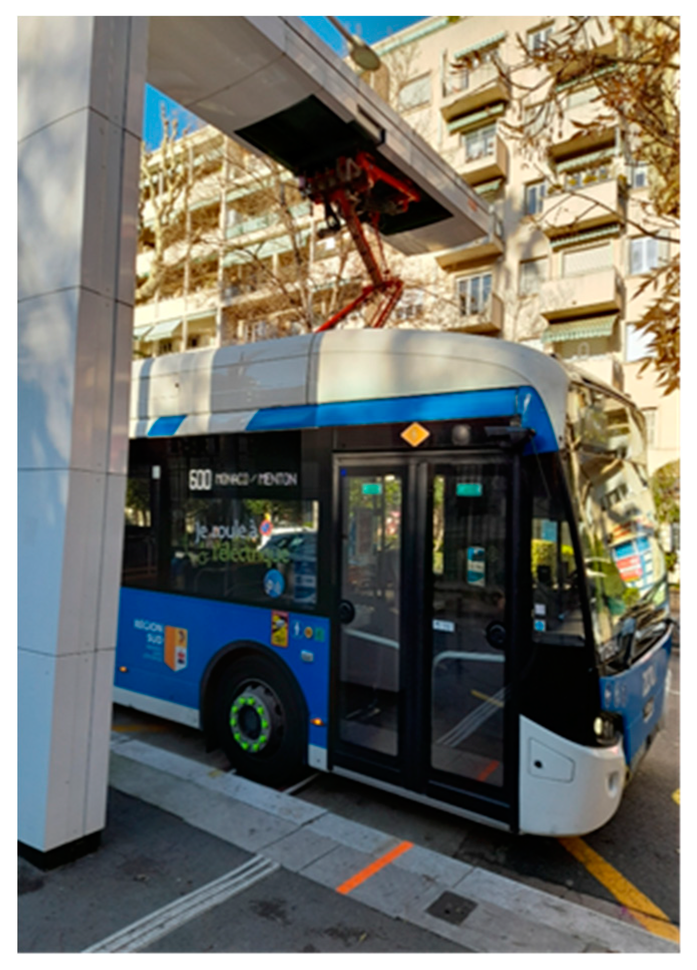
46], a one-way or circuit end stop pause charging mode using an IPT on the bus roof could be an excellent compromise with respect to battery storage, infrastructure complexity and exposure safety as shown in
Figure 3. In such a case, a bus wheel engaged in a hatch slot allows for strict vehicle positioning and a simple movable arm including the primary ICT coil could be remotely controlled to cover the secondary coil in a perfectly adapted manner with an offset sh = 0 and a smallest air gap d (see
Figure 1c). Thus, stray fields would be totally minimized and maximum efficiency achieved. Moreover, the IPT setting in the front position of the bus roof presents the furthest location from the passenger waiting platform. These conditions ensure flawless performance and health safety.
Considering the typical case of a city bus, the analysis of the charging modes will give the following estimates. Taking the storage capacity for a day mode as 200 cells, 10 circuits (round trips) per day and 10 stops per single trip. The corresponding number of cells needed would be for the different modes: 200 for day, 20 for circuit, 10 for one-way and 1 for stops mode. Excluding the case of stops due to the drawbacks mentioned above. Since the day and circuit modes require the same infrastructure layout with a single bus for the day mode and several buses for the circuit mode, which moreover requires a reduced storage volume, the choice of the circuit mode seems obvious. Indeed, for several buses doing the same circuit, one could be charged while the others are running. The case of the single trajectory mode requires two charging devices with half as many storage cells as the circuit mode and only a price comparison could decide the situation.
4. Governing Physical Phenomena and Mathematical Equations
The main physical phenomena concerned in the sustainable management in EVs are related to electric motoring, energy storage and the connection to the electric grid. The electrochemical phenomena involved in the battery storage are out of the scope of the present contribution; thus a battery is considered as an EM energy storage. The dominant physical phenomena in the design of an EM device as an electric motor or an IPT are related to the EM and electrical circuit domains. The interaction of the EMFs radiated by a wireless EM device as an IPT with the exposed substances, produces in the latter induced fields and possible unwanted thermal effects, which are governed by EM and heat transfer (HT) phenomena, coupled by the dissipated EM power (Pd) in these materials. In the case of exposure to EMFs of living tissues, a biological heat (BH) phenomenon will govern the temperature rise created by a Pd heat source. These different physical phenomena are governed by consistent mathematical equations, which are presented in the next lines.
4.1. Ruling equations
Established on Maxwell’s microscopic local behavior, under their differential form, the general EMF four equations [
47] are presented by:
The HT equation in its differential form is given by:
In the case of EMF exposure of matters the EMF harmonic fields, and heat source P
d equations are given as follows:
In the case of EMF exposure of living tissues equation 5 will be extended to the BH following equation:
In the above Equations (1)–(11), H and E are the vectors of the magnetic and electric fields in A/m and V/m, B and D are the vectors of the magnetic and electric inductions in T and C/m2, A and V are the magnetic vector and electric scalar potentials in W/m and volt. J and Je are the vectors of the total and source current densities in A/m2, σ is the electric conductivity in S/m, ρe is the volume density of electric charges in C/m3, and ω is the angular frequency = 2πf, f is the frequency in Hz of the exciting EMF. The symbol ∇ is a vector of partial derivative operators. The symbol ∂t is the operator of the partial time derivative. The magnetic and electric comportment laws, respectively, between B/H and D/E are represented by the permeability μ and the permittivity ε in H/m and F/m. The parameters: ε″ is the imaginary part of the complex permittivity of the absorbing material, and ρ is the material density in kg/m3. E is the absolute peak value of the electric field strength in V/m, c is the specific heat of the substance in J/(kg °C), k is thermal conductivity in W/(m·°C), and T is the substance temperature in °C. The power dissipation in W/m3 given by Equation (10) relates to the foremost dielectric heating of EMF energy loss. Notice that the imaginary part ε″ of the (frequency-dependent) permittivity ε is a measure of the ability of a dielectric material to convert EMF energy into heat. The volume density of power dissipations given by Equation (10) will be used in the coupling of EMF and BH equations. In the case of living tissues, we consider a self-tissue heat source Pt, convective heat transfer via irrigating fluid of tissue, and external heat source related to the EMF exposure Pd. The quantities Pt and Pd are heat sources in W/m3, Tf, and T are respectively the fluid temperature and the local temperature of tissue in °C, and cf, ρf, and pf are respectively fluid, specific heat in J/(kg °C), density in kg/m3, perfusion rate in 1/s .
Note that in the EMF equations, the source term is the excitation current density Je = σ Ee = j ω De = j ω ε Ee. Moreover, the SAR in dielectric materials (living tissues) is given by Pd/ρ in W/kg. The Pd given by (10) is function of σ or/and ω · ε″ respectively in electric conducting or dielectric behaviors of matter. At low frequencies, conductive behavior is dominant while at high frequencies it becomes negligible.
Equation (11) relates to the BH behavior of tissues considering exposure to EMFs and is similar to the Penne BH equation [
48,
49] associated with living animal tissues, accounting for convective heat transfer in blood. Animal blood acts as the sap fluid in plants. Similarly, veins and arteries, which contain blood, act as phloem and xylem containing sap. The P
t term in (11) is related to animal metabolic heat (from Penne BH equation) and corresponds to the internal heat of plant tissues. In addition, the last term in (11) corresponds to convective heat transfer in the fluid related to plant sap or animal blood. The source term in Equations (6)–(9) corresponds to an excitation current provided by an electrical circuit. Thus, in the analysis of an EM device, including electric circuits, the EM domain must be coupled to the circuit domain with a general circuit equation of the form:
In (12), “v” is the source voltage, “i” is the circuit current, “r” is the total circuit resistance, “l” a linear inductance, “C” a capacitance, “ᴕ” a non-linear voltage drop (e.g., a semiconductor) in the electrical circuit and “Ψ ” the flux linkage. The equations describing the EM and circuit domains to be solved are therefore (Equations (6)–(9) and (12)).
The electric circuits involved in the IPT are those relative to the coils of the ICT (see
Figure 1a). The involved coupling coefficient k and the resonant frequency ω
o (for coils with SS compensation) are given by:
The ICT structure, defined in
Figure 1a, and presented in
Figure 1c will be considered in the design by Equations (6)–(9) and (12) accounting for (13,14) in a strong coupled EM and electric circuit domains.
The living tissues BEs corresponding to induced fields and temperature rise, produced by a source matching to stray fields, could be obtained by solving Equations (6)–(9) and (11) with a heat source Pd relative to (10). These EM and BH domains will be coupled in a weak manner.
4.2. Numerical Computations
The solution of the various equations stated in the last section relating to the EM, BH (or HT) and electric circuit domains, (6)–(9), (11) and (12) respectively, must take into account the particular characteristics of the configurations involved. These are the geometric sophistication, the inhomogeneity of the matter, the nonlinear behaviors of the variables and the interdependence of the different domains, which imply advanced computational strategies [
50]. Satisfying these characteristics imposes a local solution in the matter advocating the use of discretized 3D procedures such as the finite element method (FEM) or equivalent approaches [
51,
52,
53,
54,
55,
56,
57] associated with appropriate equation coupling strategies. Thus, an iterative weak coupling (due to distant time constants) of the EM and BH domains would be obtained thanks to (10). In the case of taking into account the domain of electric circuits, the solution of the equations would be simultaneous reflecting a strong coupling (due to close time constants) [
58,
59,
60].
5. EMF Exposure vs Charging Routines and Living Tissues Protection
The characteristics of the ICT stray fields are directly related to the 3D relative positions of the two ICT coils (see
Figure 1a,c) fixed to the ground (transmitter) and on the underside of the vehicle (receiver) and therefore strongly affected by the positioning in the vehicle space. Thus, the exposure to the EMFs produced by the ICT stray fields is affected by the charging mode (static or dynamic) and the characteristics of the 3D coil air gap (distances d and sh -
Figure 1c).
The effects of these fields on living tissues are related to their position relative to the location of the ICT and to the 3D characteristics of the air gap of its coils. In dynamic charging mode, the stray fields are variable depending on the progressive position of the lower receiver coil of the EV relative to that of the ground-mounted transmitter. In the case of static mode, the stray fields are invariable but strongly depend on the 3D characteristics of the ICT air gap (distances d and sh).
5.1. Exposures and Charging Modes
In the case of charging modes involved in the operation of EVs, whether dynamic charging or remote static charging points (such as bus stops), the potentially affected living tissues are those of the passenger compartment inside the vehicle. In this case, passenger protection could be ensured by protecting the upper part, above the ICT of the vehicle, using shields of appropriate shape and materials [
5,
61].
In the case of the charging modes concerned by stationary EVs, whether it is classic static charging (at the station or at home) or static charging in pause (at the end-of-travel terminals of buses), the vehicle is normally empty and the living tissues potentially affected are those located outside the vehicle and near the ICT. These tissues can be humans, animals, birds, plants, etc. that could be affected by stray fields through the open space below the vehicle, coming from the ICT during the stationary static charging. The shielding of the ICT in this open space is problematic due to its 3D configuration with coils separated by an air gap between the ground and the underside of the vehicle. This difficulty would be amplified for larger twisted air gaps linked to the distances d and sh, which are difficult to control. In such conditions, the only way to preserve biodiversity is to bypass access under or near the vehicle mainly for an excessive duration; this action is part of the RA practiced by public authorities. Thus, for the ICT under the vehicle, the static charging could be carried out in closed places or surrounded areas in the case of open spaces. For the static point charging of buses, in addition to the shielding of the passenger compartment, the ICT must be placed far from the entrance and the waiting platform of the bus passengers. A smart RA-OH approach solution for this last case is the organization proposed in section 3.2. (
Figure 3) relating to the charging of buses during the break at the, end of the trajectory, stop without passengers with the ICT on its roof. This corresponds to an efficient performance and safety, in addition to the economy linked to the removal of the shielding.
5.2. Example of Exposure BEs in Human Body nearby an EV
In this section we will study an example of an assessment of the effects of EMF exposure corresponding to the determination of the fields induced in living human tissues and the verification of their compliance with safety standards.
5.2.1. Evaluation and Control of BEs
The abovementioned EMF exposure situations could be assessed and controlled by solving the equations given in
Section 4.1, allowing to check the values of the fields induced in the living tissues of the object corresponding to the standard thresholds [
62,
63,
64,
65]. Thus, the 3D calculations of the EM domain (6-9) would take into account, in the previously mentioned charging mode routines, the specific corresponding geometries involving the ICT configuration, the shield arrangement and the physical properties of the living tissues concerned. Numerical models (phantoms) could represent the living tissue object inside the vehicle or located nearby as appropriate. The substantial characteristics of these models should correspond to the consistency of the physical and biological properties, the realistic shape and the reliability with the numerical methodology used. Different body models and living tissue characteristics could be found in the literature, e.g. for human tissues [
66,
67,
68,
69,
70,
71].
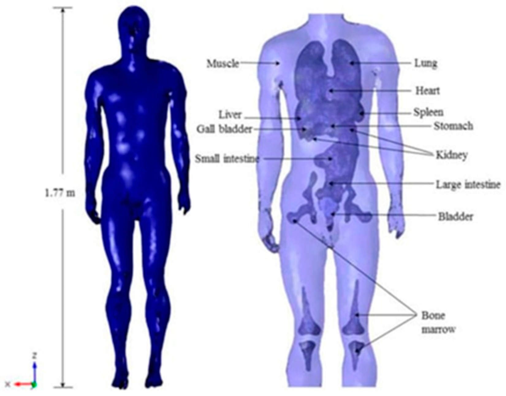
Figure 4 shows a structural human body and its various organs and tissues [
48].
5.2.2. Case of Human Body BEs Due to ICT EMF Exposure
This section concerns an illustrative example of exposure to EMFs from an ICT relative to the situation of a human body positioned horizontally on the ground next to a statically charged electric vehicle [
48].
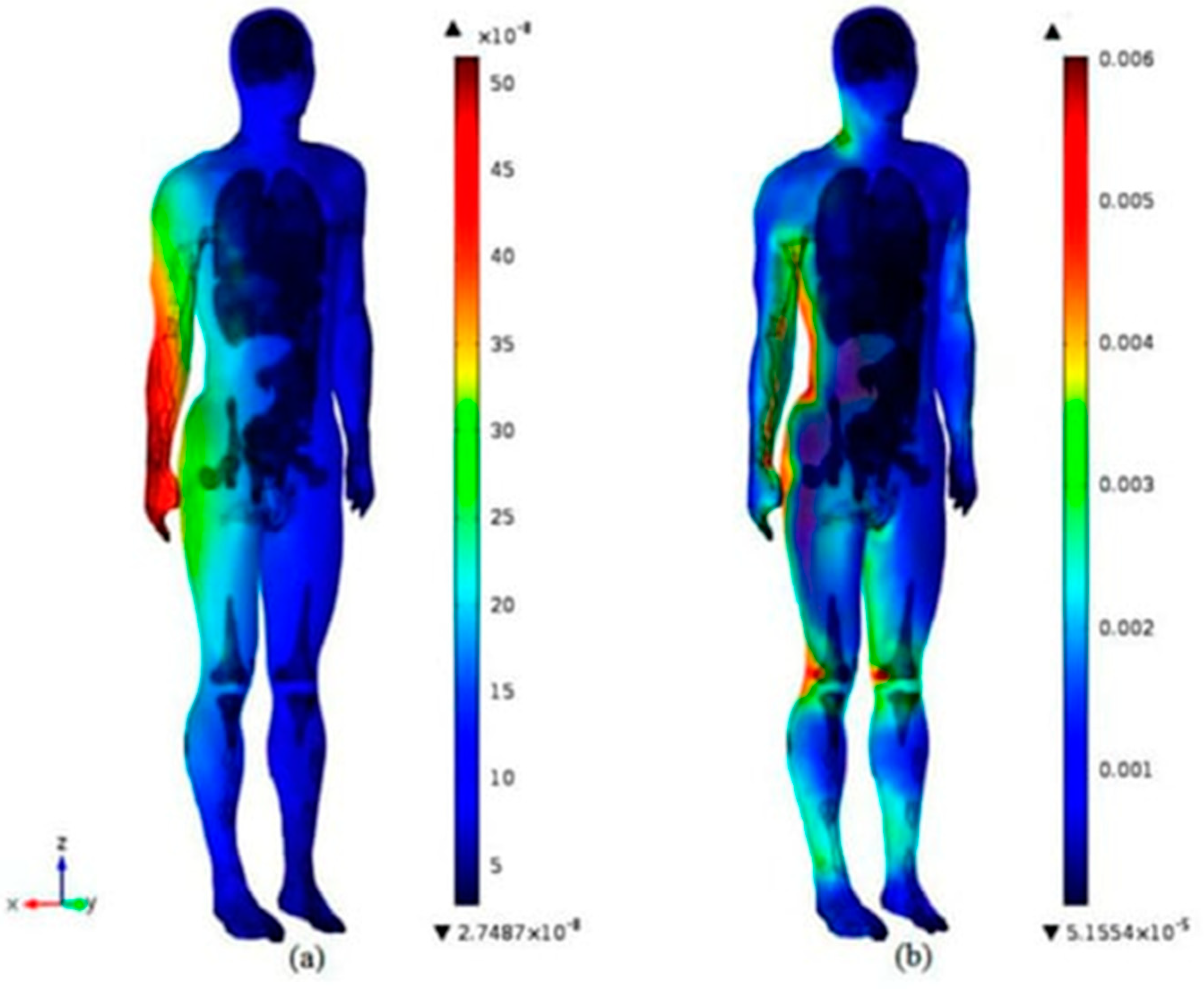
Figure 5 presents the distributions of the body-induced B and E fields due to exposure to EMFs produced by the ICT. The high-resolution body model of
Figure 4, which corresponds well to the numerical 3D FEM approach used, was used in the induced field calculations. The field distributions in
Figure 5 are relative to a source field in the solved equations (6-9) corresponding to the stray fields of a 3 kW ICT at 30 kHz. The results obtained were compared with the thresholds of the safety standards [
62,
63] fields, which are 27 μT for the magnetic induction B and 4.05 V/m for the electric field E. The correspondence check in the present example reflected the induced fields in accordance with these safety guidelines.
6. Supervision of Complex Connected Vehicle – Smart Environment – Grid
As foreseen by RA and OH approaches, appropriate eco-design, clean energy use and risk assessment are required. Thus, they allow to reduce harmful effects and preserve biodiversity and ecosystem. Moreover, RA could be involved in energy management between EV battery storages and the grid. Thus, control algorithms could be used for grid-to-vehicle (G2V), vehicle-to-grid (V2G) [
72,
73] or vehicle-to-vehicle (V2V) functional approaches [
74]. Moreover, RA includes ensuring interoperability between different sides of the IPT coil (ground and vehicle) [
36,
75], and considering an appropriate charging profile [
76]. Moreover, connectivity and autonomous driving control [
77,
78], intelligent power monitoring in EV charging [
79], consideration of battery storage [
80] or optimization via control [
81] will make EVs much more reliable.
6.1. Management of Energy Storage Associated to IPT
As discussed before, the driving range of an EV is a critical issue related to the vehicle autonomy and strongly associated with the energy storage capacity and charging strategies of the IPT. Moreover, the storage state of the battery effectively shapes the design and operation of its IPT and the connected inverter. Monitoring the storage battery state, life cycle prediction, and fault detection are important related tasks. Energy storage management through such monitoring could be realized with the technology of connected digital tools, by matching complex procedures with their virtual models, namely DTs. The concept of DTs has been used for monitoring complex systems in many fields, including the automotive industry [
82,
83]. This concept could be described as a simple data integration between a physical complex procedure and its virtual image in a bidirectional manner [
84]. DTs for EV driving routines are typically used for system condition monitoring, diagnosis, prediction, optimization, resource allocation, task offloading, and risk assessment [
85,
86,
87].
DTs can be shaped at different levels, system, subsystem, specific component, etc. Thus, the scheduled energy exchange between the EV and the grid or other sources, and the adapted IPT charging profile could be supervised by a DT as part of the battery monitoring via the RA approach. Moreover, such supervision could be supported in the context of the smart management involved in SCs using DT administration. In fact, the recently increased number of established interconnected SCs reflects an increase in the need for skills as DTs, which could contribute to the progression of these SCs [
88]. In a DT SC, detection sensors, observation cameras, and other digital tools related to the city’s resource distribution, infrastructure, logistics, people movement, and all types of EV-related concerns could collect different specific data. Thus, the SC organization would be supervised and administered more efficiently [
89].
6.2. DT Monitoring EV - IPT - Energy Storage - Grid
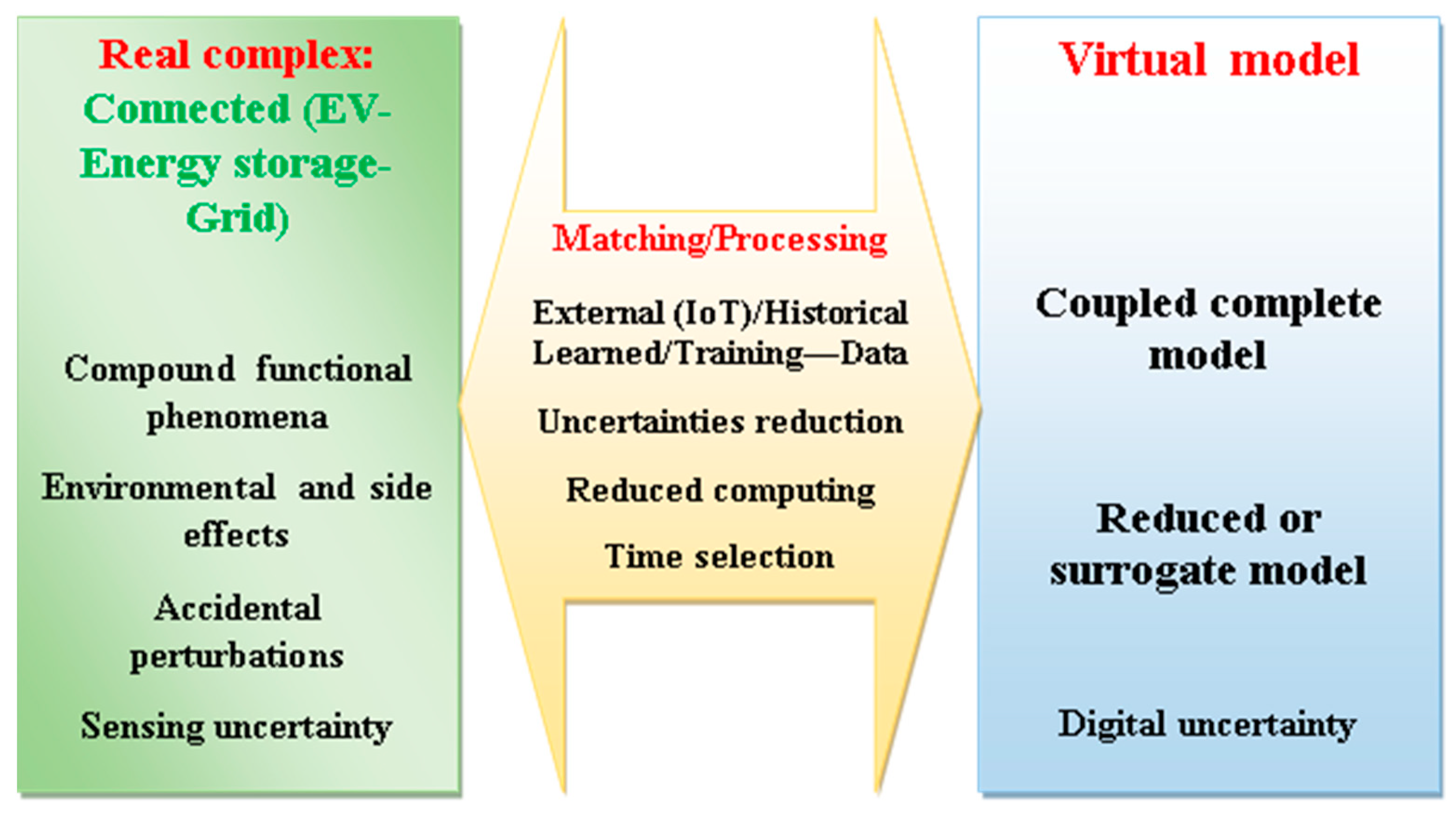
To emphasize the role of the DT concept in supervising complex procedures involving EV-IPT-energy storage batteries-grid connected to SC, we will detail at this point its main features [
90]. A DT is constituted of a physical real-virtual model, pair allowing a self- adapting conduct. Its real part conveys processed detected data to its virtual part, while the latter spreads control instructions to the real side. Such a matching decreases too, uncertainties as well as, unwanted and menacing irregularities. The real part processed data distributes sensed detections, matched and adjusted by, exterior data (IoT) and learned history. The conforming outcome would, once trained, be communicated under data analysis form. Such indications, accompanied by a suitable reduced model, will be progressed to the virtual part. Definitely, a swiftly matching demands a reliable virtual replica with a minimal computation time. This can be achieved by condensing the numerical model while preserving a realistic physical portrait using for example surrogate models [
91]. Management with such a pair permits an adaptive command for a given operational procedure [
92].
Figure 6 recapitulates the abovementioned features of a DT for the management of EV-IPT-Battery storage-grid connected to SC.
The previous analysis demonstrated the opportunity to use the RA approach in strategies regarding a scheduled energy exchange between the grid and the EV via a configurable IPT charging profile. This could be achieved through control algorithms managed by DT connected in the context of battery storage monitoring. Several applications have been published in this area, including energy storage, battery management system, state-of-charge estimation, etc., see for example [
93,
94,
95,
96].
7. Discussion
This contribution has analyzed the management of sustainable IPT devices as well as the associated energy storage and has highlighted the mathematical routines enabling the design and control tasks involved. The analyses involved are related to the RA, OH and DT approaches. Following the different analyses, several points deserve further discussion:
Innovations: As mentioned above, biodiversity and ecosystem protection could be achieved through RA and OH approaches materialized by sustainable design of EM devices. The more sophisticated the device, the more crucial the role of these approaches becomes. In fact, sophistication is generally associated with greater side effects; for example, in the present work, a faster-charging IPT device would produce higher stray EMFs. Thus, more innovations should always be accompanied by more control and adaptation. However, when it comes to innovation in general, there is a big gap between paranoia and naivety. Just remember the precautionary principle.
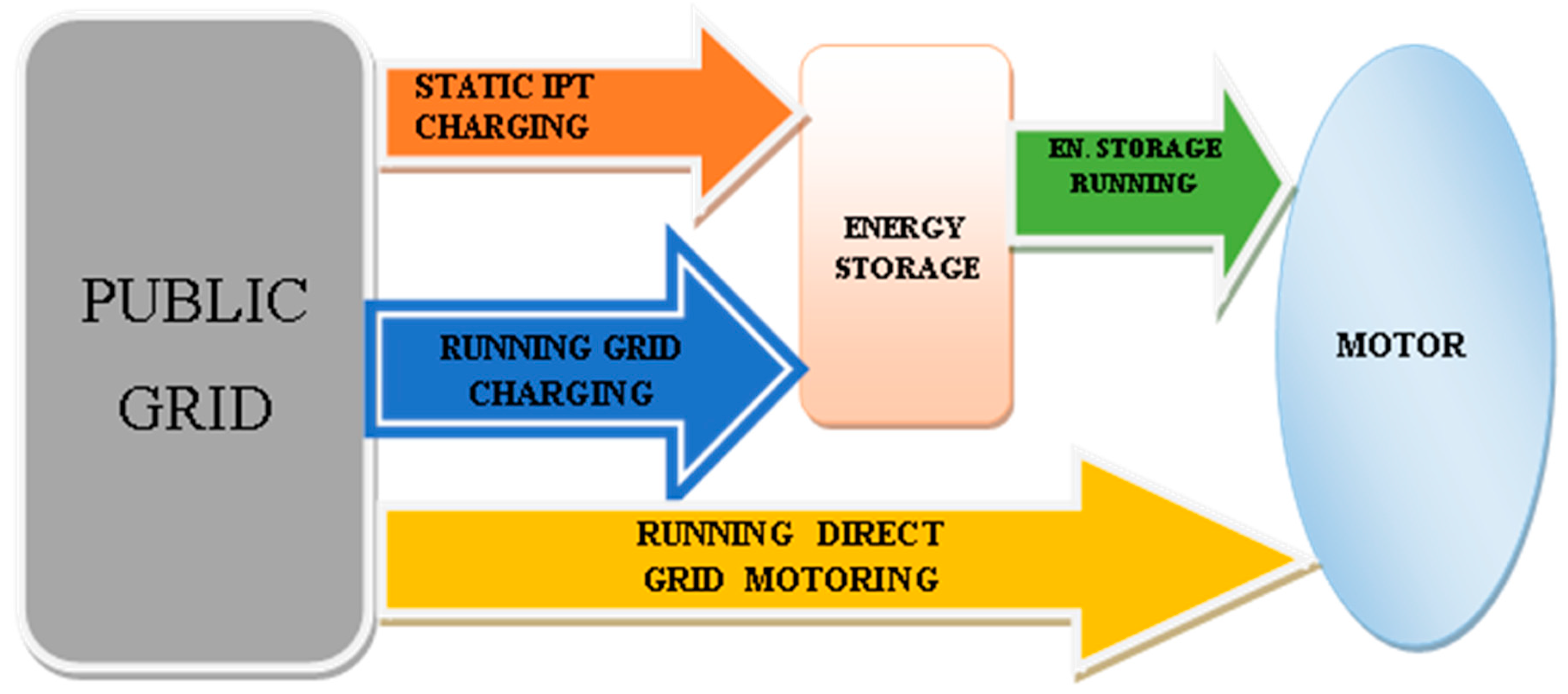
Mixed mobility: We have discussed at different places in the article about charging routines and their adapted uses. In large urban public transport like tram, a mix of charging routines and motorizations could be used in a given trajectory adapted according to the topology involved. Thus, during tram operation, the energy source could come from battery storage or from the connected grid. Similarly, direct charging from the grid during operation, or static IPT charging at the terminal stop. With these possibilities, the EV could operate in some parts of the trajectory, without grid connection (battery storage source) and other parts with grid connection (grid source for operation and direct charging) and possible static charging at the terminal. A typical example could be a tram with a trajectory partly on the surface or underground. For underground transport, the grid connection is simple and can be used for both motorization and direct charging. For surface transport, where grid connection requires more complex infrastructure, the motorization would use battery storage. In addition, the terminal break stop could be used for IPT static charging without passengers.
Figure 7 illustrates in this case the two charging modes, direct (underground) and indirect via IPT (the terminal break stop) as well as the motorization modes direct grid (underground) and energy storage (surface).
EMF Exposures: We have discussed the effects of direct exposure on living tissues of biodiversity (including humans). Exposure to EMF can also indirectly affect these living tissues through wearable or implanted tools onboard the tissues, which therefore need to be protected [
97].
Complexity: In
Section 6, we referred to the complexity of procedures. A complex procedure comprises several multiply interacting constituents typified by various phenomena acting together in an interdependent manner, which is related to the temporal and 3D spatial behaviors of the phenomena involved. The closer the time constants and the higher the local nonlinear behavior of matter in the phenomena, the deeper their interdependence and thus the greater the complexity. For distant time constants and linear behaviors, this interdependence is considerably reduced and thus the associated complexity. The notion of complexity exists in many natural and artificial occurrences [
91]. Moreover, such complexity can be treated mathematically by reflecting its multiply interacting constituents through the coupling of the equations governing the interdependent interacting phenomena (see
Section 4). The more complex the procedure, the higher the complexity of the coupled model will be. For greater interdependence (closer time constants and higher nonlinearities), the equations will be strongly coupled (simultaneous solution). For weak interdependence (distant time constants and linear behavior), the coupled solution will be weak (iterative) [
60].
History of DT: The concept of DT discussed in
Section 6 was first presented by Michael Grieves in 2002 [
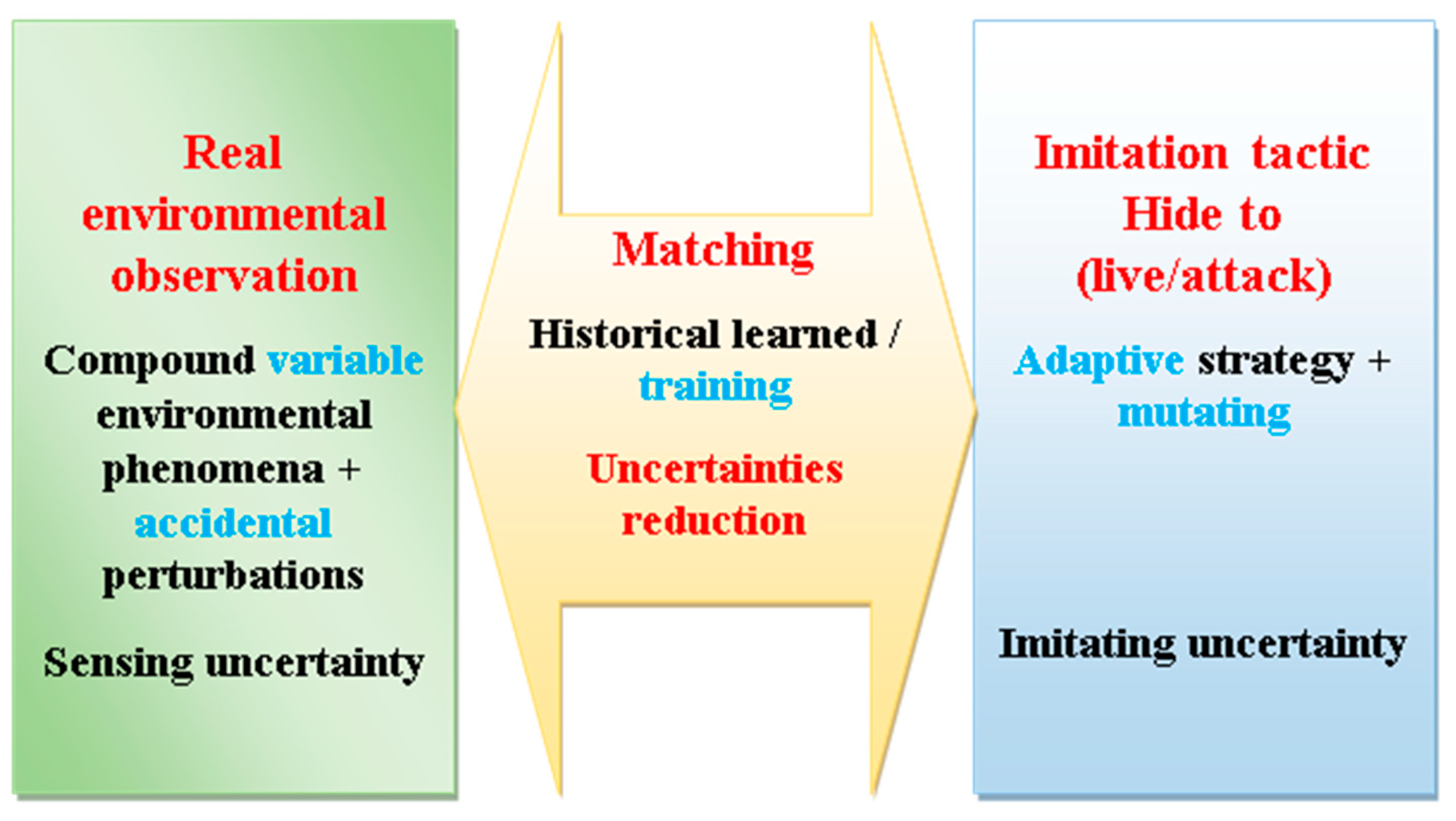
90], although its application predates this. For example, its use by NASA to safely manage a spacecraft following a disruptive oxygen tank explosion on the Apollo 13 mission in 1970. The mission subsequently modified simulators to accommodate real spacecraft conditions; this was probably the first realistic use of a DT. Furthermore, the exercise of real-virtual correspondence is related to the virtual reasoned deduction related to the observation of a phenomenon. Thus, the association of an observable and its virtual image has been and is still experimented with in frequent natural and artificial events. Members of biodiversity often rely on observation and sensory exercises, using reasoning and imitation to ensure their self-protection and survival. Logical reasoning, coupled with observation, is the most primitive of natural cognitive abilities. For example, in flora and fauna, life safety is based on observation, and experiences of imitation tactical strategy are common, which occurs through camouflage [
98]. This allows living creatures to blend into their environment through adaptive matching.
Figure 8 shows (as does
Figure 6), a representation of camouflage, emphasizing real environmental observation, the imitation tactic of obscuration, and their bidirectional link for a changing environment using real-time matching. Such obscuration allows hiding to protect one's life for prey as well as to attack for invaders. Changing environments and unexpected disturbances are matched with adaptive imitation strategies confirmed by training. Matching training helps to mitigate the uncertainties of observation, detection, and imitation strategies.
Scaling down of ICT: A reduction in the size and cost of ICT coils could be achieved by replacing wound coils with printed circuit board (PCB) technologies, see for example [
99,
100,
101]. This technology could be further investigated with a view to optimizing the coupling efficiency of ICT coils, minimizing coil resistance, reducing stray fields, etc.
8. Conclusions
The analyses performed in this paper have illustrated the role of RA, OH and DT approaches in the sustainable management of EVs energy storage with their associated IPTs allowing an optimized protection of biodiversity and the urban ecosystem. Thus, increased energy savings, reduced exposure to EMFs, optimized energy storage capacity and complexity of charging infrastructures.
The general conclusions can be summarized in the following points:
Sustainable management of EVs in urban environments such as SC is more important for public transport corresponding to the majority of users.
In public transport using IPT static charging, the choice of a small number of short charging periods in terminal stops without passengers should be encouraged. Thus, the following elements are optimized: passenger safety, energy storage volume, infrastructure complexity, shielding, etc.
Mixed modes of grid energy use adapted to the public transport trajectory with the characteristics described in the last section should be preferred.
For EVs other than public transport such as passenger cars or taxis, the necessary static IPT charging of battery should be carried out in closed rooms or bounded areas in open spaces.
Funding
This research received no external funding
Data Availability Statement
No new data were created.
Conflicts of Interest
The author declare no conflicts of interest.
References
- Mackenzie, J.S.; Jeggo, M. The One Health Approach—Why Is It So Important? Trop. Med. Infect. Dis. 2019, 4, 88. [CrossRef]
- Benis, A; Tamburis, O; Chronaki, C; Moen, A. One Digital Health: A Unified Framework for Future Health Ecosystems. J Med Internet Res. 2021, 23(2), e22189. [CrossRef]
- Elbasheir, M.S.; Saeed, R.A.; Ibrahim, A.A.; Edam, S.; Hashim, F.; Fadul, S.M. A review of EMF radiation for 5G mobile communication systems. In 2021 IEEE Asia-Pacific Conference on Applied Electromagnetics (APACE), 1-6. IEEE. Penang, Malaysia, December 2021. [CrossRef]
- Moro, S.; Linsalata, F.; Manzoni, M.; Magarini, M.; Tebaldini, S. Enhancing User Localization with an Integrated Sensing and Communication (ISAC) System: An Experimental UAV Search-and-Rescue Use Case. Remote Sens. 2024, 16, 3031. [CrossRef]
- Sagar, A.; Kashyap, A.; Nasab, M.A.; Padmanaban, S.; Bertoluzzo, M.; Kumar, A.; Blaabjerg, F. A Comprehensive Review of the Recent Development of Wireless Power Transfer Technologies for Electric Vehicle Charging Systems. IEEE Access 2023, 11, 83703-83751. [CrossRef]
- Shanmugam, Y.; Narayanamoorthi, R.; Vishnuram, P.; Bajaj, M.; AboRas, K.M.; Thakur, P. A systematic review of dynamic wireless charging system for electric transportation. IEEE Access 2022, 10, 133617-133642. [CrossRef]
- Liu, Z; Li, T; Li, S; Mi, CC. Advancements and challenges in wireless power transfer: a comprehensive review. Nexus 2024, 1:100014. [CrossRef]
- Shah, IA; Zada, M; Shah, SAA; Basir, A; Yoo, H. Flexible metasurface-coupled efficient wireless power transfer system for implantable devices. IEEE Trans. on Microwave Theory and Techniques 2024, 72:2534−47. [CrossRef]
- brahim, M.; Bernard, L.; Pichon, L.; Razek, A.; Houivet, J.; Cayol, O. Advanced modeling of a 2-kw series–series resonating inductive charger for real electric vehicle. IEEE Trans. Veh. Technol. 2015, 64, 421–430. [CrossRef]
- Razek, A. Review of Contactless Energy Transfer Concept Applied to Inductive Power Transfer Systems in Electric Vehicles. Appl. Sci. 2021, 11, 3221. [CrossRef]
- Boules, N. Electric Drives for Battery Electric Vehicles. Navigating an Electric Vehicle Future Virtual Workshop, October 25-28, 2021-The US National Academies of Sciences Electric Drives for Vehicles - National Academies of Sciences https://www.nationalacademies.org/documents/embed/link/LF2255DA3DD1C41C0A42D3BEF0989ACAECE3053A6A9B/file/D6B5A579A548566915FEC39CBDBB3EAF5E8933C796E8?noSaveAs=1 (Accessed July 29, 2024).
- Demirci, O; Taskin, S; Schaltz, E; Demirci, BA. Review of battery state estimation methods for electric vehicles - Part I: SOC estimation, Journal of Energy Storage 2024, 87, 111435. [CrossRef]
- Wang, D; Qu, X; Yao, Y; Yang, P. Hybrid Inductive-Power-Transfer Battery Chargers for Electric Vehicle Onboard Charging With Configurable Charging Profile. IEEE Transactions on Intelligent Transportation Systems 2021, 22,(1), 592-599. [CrossRef]
- Ali, A; Hudson; Sebastian, T. Apparatus and method for calibrating motor position offset using back electromotive force zero crossing detection. US Patent App. 18/116,816, 2024. Available online: https://patents.google.com/patent/US20240297600A1/en (accessed on 29 November 2024).
- José, R.; Rodrigues, H. A Review on Key Innovation Challenges for Smart City Initiatives. Smart Cities 2024, 7, 141-162. [CrossRef]
- Eskandari, M.; Savkin, A.V.; Deghat, M. Kinodynamic Model-Based UAV Trajectory Optimization for Wireless Communication Support of Internet of Vehicles in Smart Cities. Drones 2024, 8, 574. [CrossRef]
- Bastos, D.; Costa, N.; Rocha, N.P.; Fernández-Caballero, A.; Pereira, A. A Comprehensive Survey on the Societal Aspects of Smart Cities. Appl. Sci. 2024, 14, 7823. [CrossRef]
- Rajkumar, Y.; Santhosh Kumar, S.V.N. A comprehensive survey on communication techniques for the realization of intelligent transportation systems in IoT based smart cities. Peer-to-Peer Netw. Appl. 2024, 17, 1263–1308. [CrossRef]
- Razek, A. One Health Ecological Approach to Sustainable Wireless Energy Transfer Aboard Electric Vehicles for Smart Cities. Energies 2024, 17, 4349. [CrossRef]
- Ibrahim, M.; Rjabtšikov, V.; Gilbert, R. Overview of Digital Twin Platforms for EV Applications. Sensors 2023, 23, 1414. [CrossRef]
- Polat, AO; Erden, BC; Kul, S; Nasiroglu, F. Light Electric Vehicle Performance with Digital Twin Technology: A Comparison of Motor Types. Arab J Sci Eng 2024, 49, 7209–7222. [CrossRef]
- Ali, W.A.; Fanti, M.P.; Roccotelli, M.; Ranieri, L. A Review of Digital Twin Technology for Electric and Autonomous Vehicles. Appl. Sci. 2023, 13, 5871. [CrossRef]
- Venturini, S; Rosso, C; Velardocchia, M. An automotive steel wheel digital twin for failure identification under accelerated fatigue tests, Engineering Failure Analysis 2024, 158, 107979. [CrossRef]
- Gao, J.; Peng, C.; Yoshinaga, T.; Han, G.; Guleng, S.; Wu, C. Digital Twin-Enabled Internet of Vehicles Applications. Electronics 2024, 13, 1263. [CrossRef]
- Li, X.; Niu, W.; Tian, H. Application of Digital Twin in Electric Vehicle Powertrain: A Review. World Electr. Veh. J. 2024, 15, 208. [CrossRef]
- Venkatesan, S; Manickavasagam, K; Tengenkai, N; Vijayalakshmi, N. Health monitoring and prognosis of electric vehicle motor using intelligent-digital twin. IET Electric Power Applications 2019, 13, 1328-1335. [CrossRef]
- Liao, X; Zhao, X; Wang, Z ; Zhao, Z; Han, K; Gupta, R; Barth, MJ; Wu G. Driver Digital Twin for Online Prediction of Personalized Lane-Change Behavior. IEEE Internet of Things Journal 2023, 10(15), 13235-13246. [CrossRef]
- Wu, J; Li, Y; Dai, X; Gao, R; He, M. A Dynamic Power Transfer Route Construction and Optimization Method Considering Random Node Distribution for Wireless Power Transfer Network. IEEE Transactions on Power Electronics 2024, 39(4), 4858-4869. [CrossRef]
- Zhang, W; Mi, CC. Compensation Topologies of High-Power Wireless Power Transfer Systems. IEEE Transactions on Vehicular Technology 2016, 65(6) 4768-4778. [CrossRef]
- Vishnuram, P.; Panchanathan, S.; Rajamanickam, N.; Krishnasamy, V.; Bajaj, M.; Piecha, M.; Blazek, V.; Prokop, L. Review of Wireless Charging System: Magnetic Materials, Coil Configurations, Challenges, and Future Perspectives. Energies 2023, 16, 4020. [CrossRef]
- Bi, Z; Kan, T; Mi, CC; Zhang, Y; Zhao, Z; Keoleian, GA. A review of wireless power transfer for electric vehicles: Prospects to enhance sustainable mobility. Applied Energy 2016, 179, 413-425. [CrossRef]
- Ji, N; Zhu, R; Huang, Z; You, L. An urban-scale spatiotemporal optimization of rooftop photovoltaic charging of electric vehicles. Urban Info 2024, 3(4). [CrossRef]
- Afridi, K. The future of electric vehicle charging infrastructure. Nat Electron 2022, 5, 62–64. [CrossRef]
- Lee, S; Cheon, J; Park, H; Kim, D. Determination and analysis of compensation capacitor for a robust distance-variable wireless power transfer system. AIP Advances 2024, 14(11). [CrossRef]
- Aditya, K; Williamson, SS. Comparative study of series-series and series-parallel topology for long track EV charging application. 2014 IEEE Transportation Electrification Conference and Expo (ITEC), Dearborn, MI, USA, 2014, pp. 1-5. [CrossRef]
- Ibrahim, M. Wireless Inductive Charging for Electrical Vehicles: Electromagnetic Modelling and Interoperability Analysis. PhD thesis 2014. Université Paris Sud - Paris XI, 2014. English. NNT : 2014PA112369.tel-01127163.
- Wu, Y; Jiang, Y; Li, Y; Yuan, H; Wang, X; Tang, Y. Precise Parameterized Modeling of Coil Inductance in Wireless Power Transfer Systems. IEEE Transactions on Power Electronics 2024, 39(9), 11746-11757. [CrossRef]
- Hu, M; Madawala, UK. Magnetic Structure Design in IPT Systems based on Topology Optimization. IEEE Transactions on Transportation Electrification 2024, (Early Access ) 10.1109/TTE.2024.3480707.
- Shin, Y.; Rhee, J.; Woo, S. Resonance Capacitance Selection Method for Minimizing Leakage Magnetic Fields and Achieving Zero Phase Angles in Wireless Power Transfer Systems. Electronics 2024, 13, 4188. [CrossRef]
- Liorni, I.; Bottauscio, O.; Guilizzoni, R.; Ankarson, P.; Bruna, J.; Fallahi, A.; Harmon, S.; Zucca, M. Assessment of Exposure to Electric Vehicle Inductive Power Transfer Systems: Experimental Measurements and Numerical Dosimetry. Sustainability 2020, 12, 4573. [CrossRef]
- Demirci, O; Taskin, S; Schaltz, E; Demirci, BA. Review of battery state estimation methods for electric vehicles - Part I: SOC estimation, Journal of Energy Storage 2024, 87, 111435. [CrossRef]
- Etxegarai, G.; Camblong, H.; Ezeiza, A.; Lie, T.T. Design of Three Electric Vehicle Charging Tariff Systems to Improve Photovoltaic Self-Consumption. Energies 2024, 17, 1806. [CrossRef]
- Costantino, T; Miretti, F; Spessa, E. Assessing the viability of dynamic wireless power transfer in long-haul freight transport: A techno-economic analysis from fleet operators’ standpoint. Applied Energy 2025, 379, 124839. [CrossRef]
- Xie, H; Huang, R; Sun, H; Han, Z; Jiang, M; Zhang, D; Goh, HH; Kurniawan, TA; Han, F; Liu, H; Wu, T. Wireless energy: Paving the way for smart cities and a greener future. Energy and Buildings 2023, 297, 113469. [CrossRef]
- Chen, X; Wang, H. Comparative study of moisture and stress dependent unbound material modulus for flexile pavement response modeling. Transport. Geotechnics 2024, 47, 101292. [CrossRef]
- Chen, X; Wang, H; Zheng, Z; Lu, F. Electro-thermal analysis of inductively coupled power transfer in pavement for electric vehicle charging. Applied Energy 2025, 378 (A), 124809. [CrossRef]
- Maxwell, JC. VIII. A dynamical theory of the electromagnetic field. Philosophical Transactions of Royal Society 1865, 155, 459–512. [CrossRef]
- Razek, A. Biological and Medical Disturbances Due to Exposure to Fields Emitted by Electromagnetic Energy Devices—A Review. Energies 2022, 15, 4455. [CrossRef]
- Pennes, HH. Analysis of tissue and arterial blood temperatures in the resting human forearm 1948. Journal of Applied Physiology 1998, 85(1) 5–34. [CrossRef]
- Boules, N.; Douglas, K.; Feldman, S.; Fix, L.; Hager, G.; Hailpern, B.; Martial Hebert, M.; Dan Lopresti, D.; Beth Mynatt,B.; Rossbach, C.C.; et al. The future of computing research: Industry-academic collaborations. arXiv 2016, arXiv:1606.09236. [CrossRef]
- Nunes, A.S.; Chadebec, O.; Kuo-Peng, P.; Dular, P.; Meunier, G. A Coupling between the Facet Finite Element and Reluctance Network Methods in 3-D. IEEE Transactions on Magnetics 2017, 53 (10). [CrossRef]
- Henrotte, F; Geuzaine, C. Electromagnetic forces and their finite element computation. Int J Numer Model. 2024, 37(5), e3290. [CrossRef]
- Antunes, O.J.; Bastos, J.P.A.; Sadowski, N.; Razek, A.; Santandrea, L.; Bouillault, F.; Rapetti, F. Comparison between nonconforming movement methods. IEEE Trans. Magn. 2006, 42, 599–602. [CrossRef]
- Ren, Z; Razek, A. Comparison of some 3D eddy current formulations in dual systems. IEEE Transactions on Magnetics 2000, 36(4), 751-755. [CrossRef]
- Gürbüz, IT; Martin, F; Rasilo, P; Billah, MM; Belahcen, A. A new methodology for incorporating the cutting deterioration of electrical sheets into electromagnetic finite-element simulation. Journal of Magnetism and Magnetic Materials 2024, 593, 171843. [CrossRef]
- Talleb, H; Ren, Z. A new nonlinear multiscale magnetostrictive approach for FEM modelling of magnetoelectric composites under magneto-thermo-elastic loading. Composite Struct. 2023, 303:116260. [CrossRef]
- Urdaneta-Calzadilla, A.; Chadebec, O.; Galopin, N.; Niyonzima, I.; Meunier, G.; Bannwarth, B. Modeling of Magnetoelectric Effects in Composite Structures by FEM–BEM Coupling. IEEE Transactions on Magnetics 2023, 59(5), 1-4, 7000604. [CrossRef]
- de Gersem, H; Mertens, R; Lahaye, D; Vandewalle, S; Hameyer, K. Solution strategies for transient, field-circuit coupled systems. IEEE Transactions on Magnetics 2000, 36(4), 1531-1534. [CrossRef]
- Gu, B; Li, H; Li, B. An internal ballistic model of electromagnetic railgun based on PFN coupled with multi-physical field and experimental validation, Defence Technology, Volume 32, 2024, Pages 254-261. [CrossRef]
- Razek, A. Coupled Models in Electromagnetic and Energy Conversion Systems from Smart Theories Paradigm to That of Complex Events: A Review. Appl. Sci. 2022, 12, 4675. [CrossRef]
- Quercio, M; Lozito, GM, Corti, F;. Fulginei, FR; Laudani, A. Recent Results in Shielding Technologies for Wireless Electric Vehicle Charging Systems. IEEE Access 2024, 12, 16728-16740. [CrossRef]
- International Commission on Non-Ionizing Radiation Protection, 2010. Guide-lines for limiting exposure to time-varying electric and magnetic fields for low frequencies (1 Hz–100 kHz). Health Physics, 99(6), 818–836. [CrossRef]
- International Commission on Non-Ionizing Radiation Protection, 2020. Guidelines for limiting exposure to electromagnetic fields (100 kHz to 300 GHz). Health Physics, 118(5), 483–524. [CrossRef]
- U.S. Food and Drug Administration, 2020. Scientific Evidence for Cell Phone Safety. Available online: www.fda.gov/radiation-emitting-products/cell-phones/scientific-evidence-cell-phone-safety (accessed on 4 January 2024).
- Council of the European Union, 1999. EU Recommendation 1999/519/EC on the Limitation of Exposure of the General Public to Electromagnetic Fields (0 Hz to 300 GHz). Available online: https://eur-lex.europa.eu/eli/reco/1999/519/oj (accessed on 4 January 2024).
- Gabriel, S.; Lau, R.W.; Gabriel, C. The dielectric properties of biological tissues: II. Measurements in the frequency range 10 Hz to 20 GHz. Phys. Med. Biol. 1996, 41, 2251–2269. [CrossRef]
- Barchanski, A; Steiner, T.; De Gersem, H.; Clemens, M.; Weiland, T. Local grid refinement for low-frequency current computations in 3-D human anatomy models. IEEE Trans. Magn. 2006, 42, 1371–1374. [CrossRef]
- Hasgall, PA; Di Gennaro, F; Baumgartner, C; Neufeld, E; Lloyd, B; Gosselin, MC; Payne, D; Klingenböck, A; Kuster, N. iT'S Database for thermal and electromagnetic parameters of biological tissues 2022. Version 4.1. [CrossRef]
- Makarov, SN; Noetscher, GM; Yanamadala, J; Piazza, MW; Louie, S; Prokop, A; Nazarian, A; Nummenmaa, A. Virtual Human Models for Electromagnetic Studies and Their Applications. IEEE Rev. Biomed. Eng. 2017, 10, 95–121. [CrossRef]
- Harris, L.R.; Zhadobov, M.; Chahat, N.; Sauleau, R. Electromagnetic dosimetry for adult and child models within a car: Multi-exposure scenarios. Int. J. Microw. Wireless Technol. 2011, 3, 707–715. [CrossRef]
- Gjonaj, E.; Bartsch, M.; Clemens, M.; Schupp, S.; Weiland, T. High-resolution human anatomy models for advanced electromagnetic field computations. IEEE Trans. Magn. 2002, 38, 357–360. [CrossRef]
- Aktas, A; Aydin, E; Onar, OC; Su, GJ; Ozpineci, B; Tolbert, LM. Medium-Duty Delivery Truck Integrated Bidirectional Wireless Power Transfer System with Grid and Stationary Energy Storage System Connectivity. IEEE Journal of Emerging and Selected Topics in Power Electronics 2024, 12(5), 5364-5382. [CrossRef]
- Alsharif, A; Tan, CW; Ayop, R; Dobi, A; Lau, KY. A comprehensive review of energy management strategy in Vehicle-to-Grid technology integrated with renewable energy sources. Sustainable Energy Technologies and Assessments 2021, 47, 101439. [CrossRef]
- Xie, R; Liu, Q; Chen, Y; Shi, J; Yue, J; Lin, G; Chen, X; Zhang, Y.. A simple integrated solution of reconfigurable wired and wireless Vehicle-to-Vehicle (V2V) charging system. Wireless Power Transfer 2024. [CrossRef]
- Song, K.; Lan, Y.; Zhang, X.; Jiang, J.; Sun, C.; Yang, G.; Yang, F.; Lan, H. A Review on Interoperability of Wireless Charging Systems for Electric Vehicles. Energies 2023, 16, 1653. [CrossRef]
- Wang, D; Qu, X; Yao, Y; Yang, P. Hybrid Inductive-Power-Transfer Battery Chargers for Electric Vehicle Onboard Charging With Configurable Charging Profile. IEEE Transactions on Intelligent Transportation Systems 2021, 22,(1), 592-599. [CrossRef]
- Linsalata, F.; Moro, E.; Gjeci, F.; Magarini, M.; Spagnolini, U.; Capone, A. Addressing Control Challenges in Vehicular Networks Through O-RAN: A Novel Architecture and Simulation Framework. IEEE Transactions on Vehicular Technology 2024, 73(7), 9344-9355. [CrossRef]
- Hazarika, B; Saikia, P; Singh K; Li, CP. Enhancing Vehicular Networks With Hierarchical O-RAN Slicing and Federated DRL. IEEE Transactions on Green Communications and Networking 2024, 8(3), 1099-1117. [CrossRef]
- Ferretti, F; Paola, AD; Scholz, H; Tarantola, S; Kotsakis, E. Reference Power Tracking for AC Charging of Electric Vehicles. IEEE Access. [CrossRef]
- Salgado, R.M.; Danzi, F.; Oliveira, J.E.; El-Azab, A.; Camanho, P.P.; Braga, M.H. The Latest Trends in Electric Vehicles Batteries. Molecules 2021, 26, 3188. [CrossRef]
- Dong, W; Madawala, UK. Maximizing Efficiency of Hybrid Compensated Inductive Power Transfer (IPT) Systems under Load & Coupling Variations,. IEEE Journal of Emerging and Selected Topics in Industrial Electronics 2024, 99, 1-9. [CrossRef]
- Ibrahim, M.; Rassõlkin, A.; Vaimann, T.; Kallaste, A. Overview on Digital Twin for Autonomous Electrical Vehicles Propulsion Drive System. Sustainability 2022, 14, 601. [CrossRef]
- Piromalis, D.; Kantaros, A. Digital Twins in the Automotive Industry: The Road toward Physical-Digital Convergence. Appl. Syst. Innov. 2022, 5, 65. [CrossRef]
- Fuller, A; Fan, Z; Day, C; Barlow, C. Digital Twin: Enabling Technologies, Challenges and Open Research. IEEE Access 2020, 8, 108952-108971. [CrossRef]
- Bhatti, G; Mohan, H; Singh, RR. Towards the future of smart electric vehicles: Digital twin technology. Renewable and Sustainable Energy Reviews 2021, 141, 110801. [CrossRef]
- Hazarika, B; Singh, K; Paul, A; Duong, TQ. Hybrid Machine Learning Approach for Resource Allocation of Digital Twin in UAV-Aided Internet-of-Vehicles Networks. IEEE Transactions on Intelligent Vehicles 2024, 9(1), 2923-2939. [CrossRef]
- Cao, B; Li, Z; Liu, X; Lv, Z; He, H. Mobility-Aware Multiobjective Task Offloading for Vehicular Edge Computing in Digital Twin Environment. IEEE Journal on Selected Areas in Communications 2023, 41(10), 3046-3055. [CrossRef]
- White, G; Zink, A; Codecá, L; Clarke, S. A digital twin smart city for citizen feedback. Cities 2021, 110, 103064. [CrossRef]
- Mohammadi, N; Taylor, JE. Smart city digital twins. 2017 IEEE Symposium Series on Computational Intelligence (SSCI) 2017, 1-5, Honolulu, HI, USA. [CrossRef]
- Grieves, M; Vickers, J. Digital twin: Mitigating unpredictable, undesirable emergent behavior in complex systems. Trans-disciplinary Perspectives on Complex Systems; Springer: Cham, Switzerland 2017, 85–113. [CrossRef]
- Kudela, J; Matousek, R. Recent advances and applications of surrogate models for finite element method computations: A review. Soft Comput. 2022, 26, 13709-13733. [CrossRef]
- Razek, A. Monitoring Complexity in Clean Energy Systems Applications. Clean Energy and Sustainability 2024, 2, 10007. [CrossRef]
- Issa, R.; Badr, M.M.; Shalash, O.; Othman, A.A.; Hamdan, E.; Hamad, M.S.; Abdel-Khalik, A.S.; Ahmed, S.; Imam, S.M. A Data-Driven Digital Twin of Electric Vehicle Li-Ion Battery State-of-Charge Estimation Enabled by Driving Behavior Application Programming Interfaces. Batteries 2023, 9, 521. [CrossRef]
- Naseri, F; Gil, S; Barbu, C; Çetkin, E; Yarimca, G; Jensen, AC; Larsen, C; Gomes, PG. Digital twin of electric vehicle battery systems: Comprehensive review of the use cases, requirements, and platforms. Renewable and Sustainable Energy Reviews 2023, 179, 113280. [CrossRef]
- Semeraro, C; Olabi, AG; Aljaghoub, H; Alami, AH; Al Radi, M; Dassisti, M; Abdelkareem, MA. Digital twin application in energy storage: Trends and challenges. Journal of Energy Storage 2023, 58, 106347. [CrossRef]
- Waseem, M; Ahmad, M; Parveen, A.; Suhaib, M. Battery technologies and functionality of battery management system for EVs: Current status, key challenges, and future prospectives. Journal of Power Sources 2023, 580, 233349. [CrossRef]
- Razek, A. Interaction of electromagnetic fields with body-onboard devices. Explor Digit Health Technol. 2024, 2, 124–134. [CrossRef]
- Bates, HW. Contributions to an insect fauna of the amazon valley. Lepidoptera: Heliconidae. Trans Linnean Soc London. 1862, 23(3), 495-566. [CrossRef]
- Narvaez, A; Carretero, C; Lope I; Acero, J. Printed Circuit Board Coils of Multitrack Litz Structure for 3.3-kW Inductive Power Transfer System. IEEE Transactions on Transportation Electrification 2023, 9(3), 3947-3957. [CrossRef]
- Nomoto, S; Shimura, S; Kusaka, K; Takada, T. Splitting Conductors of Coils on PCB for AC-resistance Reduction. IEEJ Journal of Industry Applications 2024, 13(6), 743-744. [CrossRef]
- Lewis, DD; Onar, O; Gastineau, L; Eastham, JF; Ionel, DM. High-Power Polyphase PCB-Type Inductive Coupler for Wireless Electric Vehicle Charging. 2024 IEEE Transportation Electrification Conference and Expo (ITEC), Chicago, IL, USA, 1-6. [CrossRef]
|
Disclaimer/Publisher’s Note: The statements, opinions and data contained in all publications are solely those of the individual author(s) and contributor(s) and not of MDPI and/or the editor(s). MDPI and/or the editor(s) disclaim responsibility for any injury to people or property resulting from any ideas, methods, instructions or products referred to in the content. |
© 2024 by the authors. Licensee MDPI, Basel, Switzerland. This article is an open access article distributed under the terms and conditions of the Creative Commons Attribution (CC BY) license (http://creativecommons.org/licenses/by/4.0/).