
Submitted:
24 December 2024
Posted:
24 December 2024
You are already at the latest version
Abstract
The efficient hydrogenation of 1-butene is an industrially significant reaction for producing fuels and value-added chemicals. However, achieving high catalytic efficiency and stability remains challenging, particularly for cost-effective materials, such as Ni. In this study, we developed a porous Ni-coated Ni foam catalyst by electrostatic spray deposition to address these challenges. The catalyst exhibited a turnover frequency approximately ten times higher than that of either porous Ni or Ni foam alone. This enhancement was attributed to the formation of interfacial active sites, which facilitated improved reactant adsorption and activation during hydrogenation. The electrostatic spray deposition technique ensured a uniform and controlled coating, enabling pre-cise engineering of the catalyst structure and interface. The post-deposition heat treatment was further optimized to enhance structural integrity and catalytic performance. This study highlights the importance of interface engineering and structural optimization in catalyst design and pro-vides valuable insights into the development of efficient Ni-based catalysts for industrial hy-drogenation applications. These findings emphasize the potential of electrostatic spray deposition as a versatile method for fabricating advanced catalytic systems.
Keywords:
Porous Ni
; Ni foam
; 1-Butene hydrogenation
; Interfacial active sites
1. Introduction
The hydrogenation of olefins, such as 1-butene, is a crucial process in the production of fuels, polymers, and various high-value chemicals, making it an essential process in the chemical industry. Despite its importance, the development of catalysts with high efficiency, stability, and cost effectiveness remains challenging. Ni-based catalysts are widely used for hydrogenation because of their robustness, affordability, and excellent catalytic activity [1,2,3]. Porous Ni has garnered significant attention as a catalyst because of its high density of active sites, which facilitates hydrogenation reactions [4,5,6]. However, its structural instability and performance limitations under prolonged reaction conditions hinder its widespread applications.
An effective strategy to overcome these challenges involves combining porous nickel with nickel foam. As a supporting material, nickel foam provides notable advantages, including superior mechanical strength, outstanding electrical conductivity, and an extensive surface area. This combination results in unique interfacial active sites, which enhance the catalytic performance by improving reactant adsorption and activation while accelerating reaction kinetics [7,8,9]. These structural and interfacial synergies are particularly effective for hydrogenation reactions, where surface interactions critically influence the catalytic activity.
The fabrication of these composite structures requires advanced techniques to ensure their uniformity and stability. Electrostatic spray coating has emerged as an efficient method for the controlled deposition of porous Ni on Ni foam. This technique ensures homogeneous coating and precise control over the interface, which is crucial for maximizing the active site exposure and catalytic performance [10,11,12]. Furthermore, heat treatment after coating can optimize the particle-Ni foam interfacial characteristics, enhancing the activity and durability of the catalyst. Recent studies have shown that interface tuning is crucial to enhancing the efficiency of Ni-based catalysts in industrial hydrogenation.
In this study, the powder-coated Ni foam structures were fabricated by electrostatic spray deposition. The process parameters, including the coating and post-treatment conditions, were systematically optimized to control the interfacial properties between the Ni particles and Ni foam. This study highlights the significance of interfacial engineering and process control in the development of advanced catalysts, providing new insights into the design of highly efficient and durable materials for hydrogenation reactions.
2. Materials and Methods
2.1. Synthesis of Porous Ni Particles
Porous Ni particles used in this study were synthesized following the method reported by Park et al. [6]. The synthesis involved spray pyrolysis of a precursor solution containing 0.1 M Ni acetate tetrahydrate (Ni(OCOCH3)2·4H2O) and 100 nm-sized polystyrene (PS) beads in distilled water, with a molar ratio of Ni:PS = 1:20. Following spray pyrolysis at 700 °C in a nitrogen atmosphere, the product was collected in a powder form and subjected to heat treatment at 550 °C in a hydrogen atmosphere to remove the PS beads and form porous Ni particles.
2.2. Deposition of Porous Ni Particles on the Ni Foam
Porous Ni oxide particles prepared via SP were deposited on Ni foam by electrospray deposition (ESD). A dispersed solution of these particles was prepared by adding 1 wt% porous particles to ethanol (95%, Sigma-Aldrich), and then sprayed with a syringe pump from the nozzle. The Al foil was placed under the nozzle with an applied high negative voltage, and the 1200 μm Ni foam of size of 10 × 10 × 0.3 cm3) was placed on the Al foil as a support. The distance between the nozzle and the Ni foam was 3 cm. The solution as a droplet was supplied to the Ni foam by an electrical field with an applied voltage of 13 kV, and the flow rate of the feed solution was 5 μL/min. The nozzle diameter was 0.65 mm and the experiment was conducted in an acrylic chamber at room temperature. The resulting solution was heat-treated in a box furnace at 600 °C under H2 gas at a heating rate of 5 °C/min without any retention time for reducing the Ni oxide to Ni particles and bonding between the particles and foam with solvent evaporation.
2.3. Characterization
The morphological and pore characteristics of the synthesized samples were examined by field-emission scanning electron microscopy (FE-SEM, JSM-7001F) and FE-transmission electron microscopy (JEM-2100F (HR)). The crystal structure and composition of the samples were analyzed by X-ray diffraction (XRD, D/Max-2500VL) with Cu-Kα radiation (λ = 1.5418 Å). The oxidation states of the surface elements in the samples were analyzed by X-ray photoelectron spectroscopy (XPS) (Thermo Fisher Scientific K-Alpha and NEXSA instruments). An Al Kα source was used for measurements, which utilized the adventitious C 1s peak at 284.6 eV.
2.4. 1-Butene Hydrogenation Reaction
The hydrogenation of 1-butene to butane was conducted in a flow reactor constructed from quartz tubing (inner diameter: 1.0 cm, outer diameter: 1.5 cm, length: 50 cm) under atmospheric pressure. A 50 mg sample was positioned at the center of the reactor using a quartz holder. A gas mixture comprising 1-butene and hydrogen was introduced into the reactor, with 1-butene delivered at a rate of 5 mL/min via a syringe pump preheated to 100 °C, while hydrogen was supplied at a flow rate of 100 mL/min. The reaction was performed at 100 °C under continuous hydrogen flow. The resulting butane, the primary reaction product, was quantified using gas chromatography.
3. Result and Discussion
3.1. Preparation Process for the Porous Ni-Coated Ni Foam
Figure 1 illustrates the preparation of porous Ni-coated Ni foam using an electrospray deposition (ESD) method followed by a reduction treatment. This approach was designed to deposit porous NiO particles onto Ni foam, which served as a stable catalyst with reduced material usage for catalytic reactions. In the initial step, porous NiO particles were deposited on the Ni foam surface via ESD. A positively charged spray of NiO particles was directed toward the negatively charged Ni foam, which was driven by the electrostatic force difference between the powder solution and the foam substrate [13]. The ESD process ensured the uniform deposition of porous NiO particles by optimizing critical parameters, such as the applied voltage, solution concentration, number of nozzles, and solution injection rate [14]. These carefully controlled conditions ensured a consistent NiO coating across the foam surface, creating a uniform catalyst layer. Following deposition, the coated Ni foam underwent a high-temperature reduction process in a hydrogen atmosphere. During this step, NiO particles were converted into porous metallic Ni as oxygen was removed from the NiO structure. This transformation enhanced the electrical conductivity and catalytic activity of the material while maintaining its porous structure. The reduction process also facilitated strong adhesion between the porous Ni and the foam substrate, minimizing particle detachment during the operation [15]. The final product, a porous Ni-coated Ni foam, exhibited a high surface area and a well-integrated porous Ni layer, offering excellent catalytic properties and structural stability. The ESD method enabled the precise control over catalyst deposition by reducing the amount of material required while ensuring uniform particle distribution and effective utilization of the active sites [16]. These features render the porous Ni-coated Ni foam highly effective for catalytic applications, such as hydrogenation, where durability and efficiency are critical.
Figure 2a shows the SEM image of the pristine Ni foam, which exhibits a smooth and clean surface without any deposited particles. The interconnected framework of the Ni foam provides a robust mechanical structure and high surface area, making it a suitable support for catalyst deposition [17]. Figure 2b shows that the Ni foam surface becomes rough after the ESD of porous NiO owing to the uniform coverage of the porous NiO particles, which are evenly distributed across the foam. The inset highlights the fine structure of the porous NiO particles, which exhibit a high surface area and porosity, which are the key characteristics responsible for enhancing catalytic performance [18]. A uniform distribution of particles was achieved through optimized electrospray conditions, ensuring the effective utilization of the support structure. Figure 2c shows the Ni foam after reduction, where the porous NiO particles are converted into porous metallic Ni. The foam retained the rough surface, as shown in Figure 2b, with a well-distributed layer of the porous metallic Ni. The inset provides a closer view, confirming the preservation of the porous structure during reduction. This porous metallic Ni layer enhanced the number of active sites available for catalytic reactions, improving the overall performance of the material [19]. Figure 2d shows an enlarged image of the porous Ni particles after reduction. The porous particles exhibited well-defined architectures with interconnected pores, facilitating the diffusion of reactants and products during catalytic reactions. This highly porous structure improved the accessibility of active sites and ensured strong adhesion to the Ni foam substrate, contributing to the mechanical stability of the material during operation [20]. These SEM images collectively demonstrated that ESD, combined with a hydrogen reduction step, successfully transformed the pristine Ni foam into a robust and porous Ni-coated material. Therefore, the resulting structure, which is characterized by high porosity, uniform distribution, and strong adhesion, is ideal for applications requiring efficient and stable catalysts, such as hydrogenation reactions and other catalytic processes.
3.2. Influence of the Reduction Temperature and Coating Conditions on the Porous Ni Particles
Figure 3 illustrates the effect of the coating conditions and reduction temperature on the properties of the porous Ni particles supported on the Ni foam. The amount of coating and the reduction process were controlled by varying the concentrations of the solution used for coating and the reduction temperature. The results are discussed in terms of the desorption weight percentage (a) and XRD patterns (b). Figure 3a shows the desorption weight percentage data, revealing the influence of the reduction temperature on the adhesion of the Ni particles to the foam surface after sonication. Without heating, the desorption percentage reached its highest value at 12.8 wt%, indicating poor adhesion and a substantial loss of particles upon sonication [21]. At 400 °C, the desorption percentage decreased to 4.4 wt%. At 600 °C, the desorption percentage decreased to nearly zero (0.3 wt%), indicating strong particle adhesion with negligible detachment after sonication. This finding suggested that reduction at 600 °C effectively anchored the particles onto the Ni foam. No desorption was observed at 800 °C, indicating the complete stabilization of particles and highlighting the critical role of the reduction temperature in enhancing the adhesion and integration of particles on the Ni foam surface. Figure 3b shows the XRD patterns, which provide insights into the structural and phase transitions of the Ni particles depending on the reduction temperature. At 400 °C, the peaks corresponding to Ni oxide (NiO) at approximately 37°, 43°, and 62° indicated that the particles were primarily composed of NiO [22]. At 600 °C, the intensity of these NiO peaks decreased significantly, and peaks corresponding to metallic Ni appeared at 44.5°, 51.8°, and 76.4°, signifying a phase transition from NiO to metallic Ni [22]. Notably, no particle aggregation was observed at this temperature, suggesting that reduction facilitated a uniform phase transformation without particle coalescence. At 800 °C, the NiO peaks disappeared completely, with a predominance of the metallic Ni peaks, confirming the complete reduction of NiO to Ni and the preservation of particle structure. These results indicated that at 600 °C particle desorption was nearly eliminated, and a clear phase transition from NiO to metallic Ni occurred, without significant particle aggregation. This finding demonstrated that 600 °C was an optimal reduction temperature for achieving strong particle adhesion and effective phase transformation while maintaining the structural integrity of particles. The ability to control the coating amount and reduction process by adjusting the solution concentration and reduction temperature underscores the importance of these parameters in tailoring the properties of the Ni-coated Ni foam for catalytic or other applications.
Figure 4 shows the XRD patterns of the porous Ni oxide (black) and porous Ni (red) deposited on the Ni foam after reduction, following the optimized conditions identified in Figure 3. These patterns highlighted the transformation of NiO into the metallic Ni and illustrate the effectiveness of reduction. The XRD pattern of the porous Ni oxide exhibited distinct peaks at approximately 37°, 43°, and 62°, corresponding to the (111), (200), and (220) crystal planes of NiO, respectively [22]. These peaks confirmed the crystalline nature of Ni oxide before reduction, consistent with the previously reported NiO structures [22]. After reduction, the XRD pattern of porous Ni exhibited sharp peaks at 44.5°, 51.8°, and 76.4°, corresponding to the (111), (200), and (220) crystal planes of metallic Ni [22]. The disappearance of the NiO peaks and the emergence of only metallic Ni peaks confirmed the successful conversion of Ni oxide to metallic Ni under optimized reduction conditions. This complete phase transition corroborates the results from Figure 3, where reduction at 600 °C eliminates the adsorbed species and enables full conversion. The high intensity and sharpness of the metallic Ni peaks indicated a well-formed crystalline structure, suggesting that the reduction process enhanced the crystallinity of Ni particles while ensuring strong adhesion to the Ni foam substrate. In addition, the absence of secondary phases, such as mixed oxides or intermediate species reflected the efficiency of the reduction process in achieving a clean and uniform transformation without aggregation or structural defects. This result demonstrated that the optimized reduction process effectively converted NiO to metallic Ni while preserving the structural integrity of the particles. This precise phase control and crystallinity enhancement rendered the reduced porous Ni material highly suitable for catalytic and other advanced applications. These findings emphasize the importance of carefully controlling the reduction conditions for producing high-quality Ni coatings on the Ni foam.
3.3. Oxidation States of the Porous Ni and Ni Oxide-Coated Ni Foam
Figure 5 shows the XPS results of the porous Ni and Ni oxide (NiO) samples, highlighting their surface chemical states and catalytic properties. Figure 5a shows the XPS Ni 2p spectra of the four samples,porous Ni, NiO, NiO-coated Ni foam, and Ni-coated Ni foam, revealing peaks corresponding to different oxidation states, including metallic Ni, NiO, Ni(OH)2, and Ni(OOH), respectively. The metallic Ni peak was observed at approximately 852.6 eV, NiO near 854.0 eV, Ni(OH)2 at approximately 855.6 eV, and Ni(OOH) at approximately 856.5 eV [23]. These variations in the peak positions and intensities provide critical insights into the surface oxidation states and chemical compositions of the samples, which are essential for understanding their catalytic behavior. Figure 5b shows the relative peak areas of Ni 2p (%), highlighting the differences in the oxidation state distributions of the samples. Ni0, NiO, Ni (OH)2, and Ni(OOH) account for 46%, 28%, 18%, and 8% of the porous Ni, respectively. For porous NiO, NiO was dominant at 47%, followed by Ni(OH)2 (32%), Ni0 (12%), and Ni(OOH) (9%). The porous Ni-coated Ni foam exhibited a higher proportion of Ni0 (60%) and NiO (17%), with smaller contributions from Ni(OH)2 (11%) and Ni(OOH) (11%). The porous NiO-coated Ni foam was characterized by 7% Ni0, 16% NiO, 71% Ni(OH)2, and 7% Ni(OOH). These differences emphasized the variation in the oxidation states and chemical compositions resulting from coating and reduction. The schematic in Figure 5c illustrates the oxidation processes and structural changes in the porous Ni and NiO samples. The superior catalytic performance of the porous Ni/Ni foam in the hydrogenation reactions can be attributed to its optimized surface chemistry and composition. The XPS data revealed a balanced coexistence of metallic Ni and NiO in this sample, which is essential for the catalytic activity. Metallic Ni facilitates the adsorption and activation of the hydrogen molecules, whereas NiO stabilizes the reaction intermediates and supports the reaction pathways. In addition, the moderate presence of Ni(OH)2 contributes to the catalytic stability and efficiency [3,24]. The high electrical conductivity of the metallic Ni and oxygen-supplying capability of NiO create an ideal environment for hydrogenation reactions. Furthermore, the porous structure enhances the catalyst performance by increasing the surface area and active site density and improving the contact between the reactants and the catalyst. These combined factors explain the superior catalytic properties of the porous Ni/Ni foam, making it an excellent material for hydrogenation applications.
3.4. Catalytic Performance of the Ni foam under 1-Butene Hydrogenation Reaction
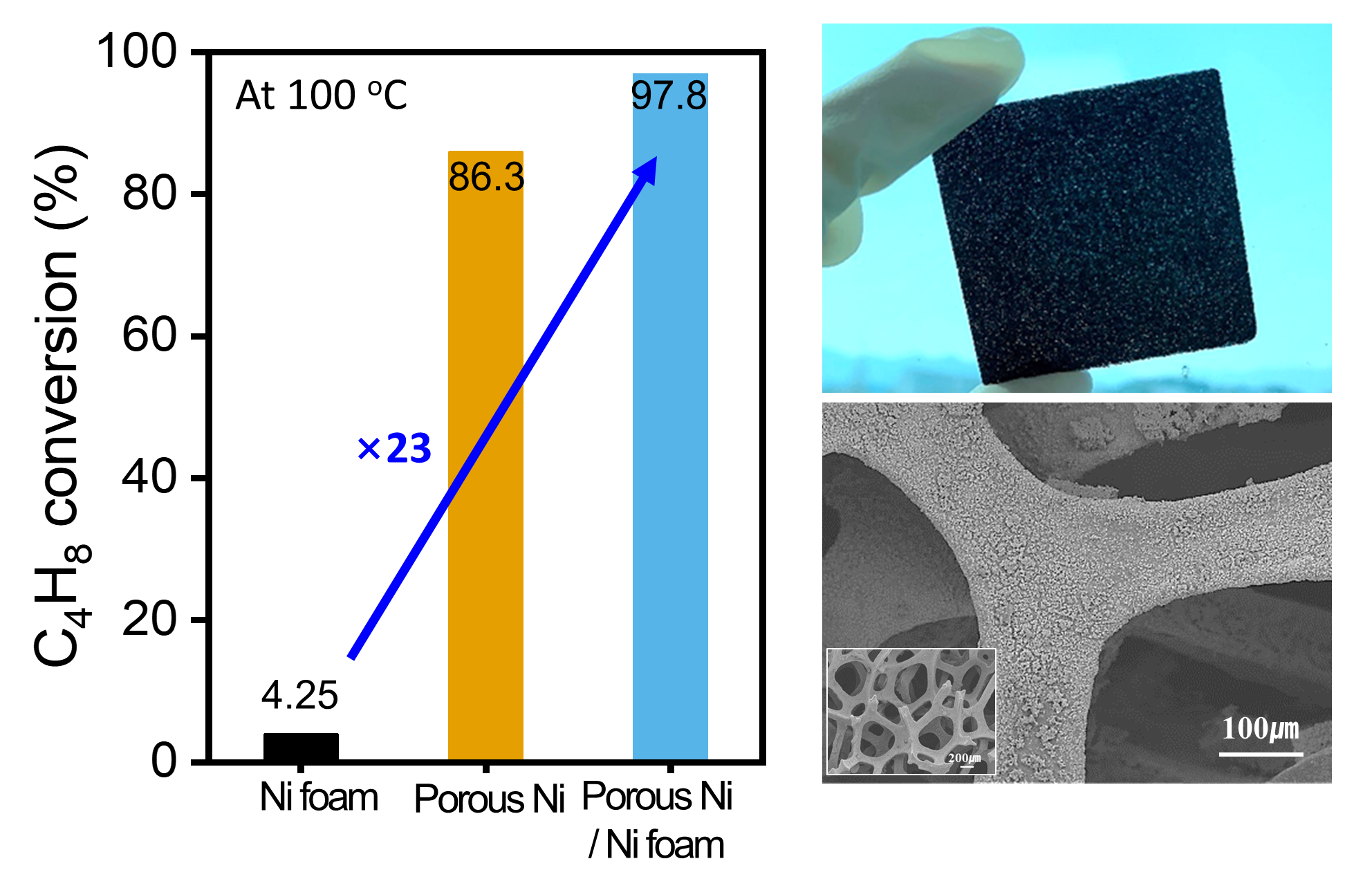
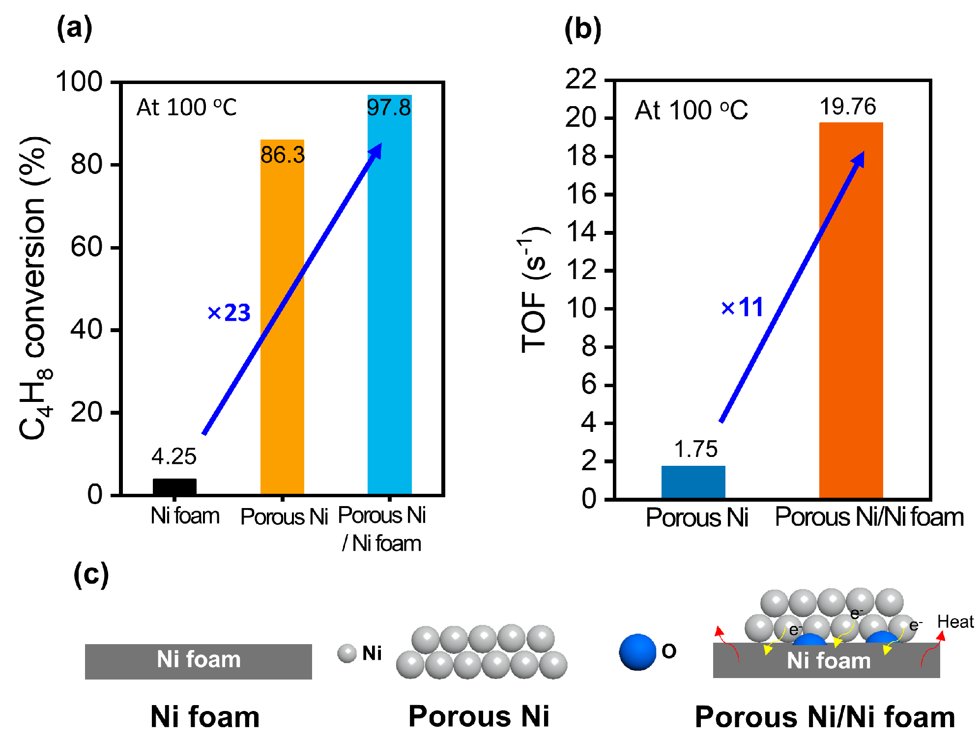
Figure 6 shows the catalytic behavior of the Ni foam, porous Ni, and porous Ni-coated Ni foam in the hydrogenation of 1-butene at 100 °C, with data focusing on the conversion efficiency, turnover frequency (TOF), and structural characteristics. Figure 6a shows the conversion of 1-butene to 1-butane, demonstrating a clear hierarchy in their catalytic performance. The Ni foam achieved only 4.25% conversion, which was significantly lower than those of the porous Ni (86.3%) and porous Ni-coated Ni foam (97.8%). The 23-fold improvement in conversion for the porous Ni-coated Ni foam compared to the Ni foam underscores the crucial role of the porous structure and additional Ni coating in increasing the catalytic activity. This enhancement could be attributed to the increased surface area and accessible active sites provided by the tailored design of the material. Figure 6b shows the TOF values and provides further evidence of the superior catalytic performance of the porous Ni-coated Ni foam. The TOF, which quantifies the number of reactant molecules converted per second per mole of active Ni sites, is calculated as follows [25]:
Based on this calculation, the porous Ni-coated Ni foam achieved a TOF of 19.76 s−¹, which was 11 times greater than that of the TOF of the porous Ni (1.75 s−¹). This significant enhancement demonstrated the efficient utilization of the active Ni sites in the porous Ni-coated Ni foam, likely attributed to the synergy between the high surface area and the optimized distribution of the Ni species. The additional Ni coating promotes hydrogen adsorption and activation, which are critical steps in the hydrogenation reaction. Figure 6c shows a schematic of the structural differences between the three catalysts. Ni foam, with its relatively smooth and nonporous surface, provides limited active sites and consequently exhibits poor catalytic activity. However, porous Ni has a larger surface area with more accessible active sites, resulting in moderate performance. The porous Ni-coated Ni foam combines these advantages with an additional layer of Ni to enhance the density and availability of active sites. This combination improves the catalytic efficiency and facilitates superior interaction with the reactants, enabling superior hydrogenation performance. In conclusion, the porous Ni-coated Ni foam demonstrated exceptional activity in the hydrogenation of 1-butene, outperforming the Ni foam and porous Ni. The optimized structure, improved active site density, and efficient utilization of Ni contributed to its high conversion rate and TOF, rendering it a highly effective catalyst for hydrogenation reactions.
4. Conclusions
This study demonstrates the successful preparation and characterization of a porous Ni-coated Ni foam through a combination of ESD and hydrogen reduction. The ESD process enabled the uniform and precise coating of porous NiO particles onto the Ni foam substrate, driven by electrostatic interactions. The deposited particles exhibited a well-distributed porous structure, which was retained after reduction. The post-deposition reduction in a hydrogen atmosphere effectively converted the porous NiO into metallic Ni, with optimized conditions at 600 °C, ensuring complete phase transformation while preserving the porous morphology and maintaining strong adhesion to the foam. Structural analysis using SEM confirmed the transformation of the smooth Ni foam surface into a rough, porous, Ni-coated material with a high surface area and interconnected pores, which is ideal for its catalytic applications. The XRD results validated the phase transition from NiO to Ni during reduction, with no evidence of the intermediate phases or particle aggregation. XPS analysis further revealed a balanced presence of the metallic Ni and NiO in the reduced samples, highlighting the importance of surface composition in achieving superior catalytic performance. The porous Ni-coated Ni foam produced in this study demonstrated a combination of high surface area, abundant active sites, and robust structural stability, making it highly effective for catalytic applications, such as hydrogenation. The ESD process, coupled with precise reduction conditions, provides a scalable and versatile method for tailoring material properties to meet specific application requirements. This approach established a strong foundation for the development of advanced catalytic materials with enhanced efficiency, stability, and durability.
Author Contributions
Conceptualization, methodology, formal analysis, visualization, writing of the original draft, review&editing: D.P.; Methodology and Conceptualization: H.K.; Formal analysis: Y.K. All authors have read and agreed to the published version of this manuscript.
Funding
This study received no external funding.
Data Availability Statement
The datasets are available on reasonable request.
Acknowledgments
This work was financially supported by the National Research Council of Science & Technology (NST) funded by the Korean Government (MSIT) [grant number CAP22082-100], the Ministry of Trade, Industry & Energy (MOTIE) of the Republic of Korea [grant number 20019175], and KIMS Principal R&D [grant code number PNK9830].
Conflicts of Interest
The authors declare no conflict of interest.
References
- Boudart, M. Catalysis by Supported Metals. Adv. Catal. 1969, 20, 153–166. [Google Scholar]
- Hu, Y.; Liu, M.; Bartling, S.; Lund, H.; Atia, H.; Dyson, P.J.; Beller, M.; Jagadeesh, R.V. A general and robust Ni-based nanocatalyst for selective hydrogenation reactions at low temperature and pressure. Sci. Adv. 2023, 9, eadj8225. [Google Scholar] [CrossRef] [PubMed]
- Yamanaka, N.; Shimazu, S. Selective Hydrogenation Properties of Ni-Based Bimetallic Catalysts. Eng. 2022, 3, 60–77. [Google Scholar] [CrossRef]
- Klausfelder, B.; Kempe, R. A Highly Active Nickel Catalyst for the Selective Hydrogenation of Functionalized Nitroarenes, Z. fur Anorg. Allg. Chem. 2023, 649, e202300071. [Google Scholar] [CrossRef]
- Qiao, X.L.; Niu, L.B.; Zhang, H.L.; Wen, X.; Cao, Y.Y.; Bai, G.Y. Controllable fabrication of a novel porous Ni-alginate hybrid material for hydrogenation. Appl. Catal. B-Environ. 2017, 218, 721–730. [Google Scholar] [CrossRef]
- Park, D.; Yun, J.Y.; Hong, S.; Yang, S.; Koo, H.Y.; Park, J.Y.; Kim, K.T. Enhanced hydrogenation conversion efficiency of porous nickel particles with homogeneously distributed unimodal nanopores. Scr. Mater., 2022, 216, 114761. [Google Scholar] [CrossRef]
- Dedov, A.G.; Loktev, A.S.; Shmigel, A.V.; Tikhonov, P.A.; Lapshin, A.E.; Arsent'ev, M.Y.; Mukhin, I.E.; Ivanov, V.K.; Moiseev, I.I. Selective conversion of methane to synthesis gas: Catalysts based on electrochemically modified nickel foam. Pet. Chem. 2017, 57, 230–235. [Google Scholar] [CrossRef]
- Pierozynski, B.; Mikolajczyk, T. Cathodic evolution of hydrogen on platinum-modified nickel foam catalyst. Electrocatalysis. 2016, 7, 121–126. [Google Scholar] [CrossRef]
- Ren, Z.N.; Zhang, J.B.; Bai, Y.H.; Wang, J.F.; Chen, H.Y.; Hao, Q.Q.; Ma, X.X. Unsupported Ni catalyst prepared from Ni foam for methane decomposition and recycling the carbon-deposited spent catalyst. Int. J. Hydrogen Energy. 2021, 46, 21853–21865. [Google Scholar] [CrossRef]
- Koh, B.S.; Yoo, J.H.; Jang, E.K.; Jothi, V.R.; Jung, C.Y.; Yi, S.C. Fabrication of highly effective self-humidifying membrane electrode assembly for proton exchange membrane fuel cells via electrostatic spray deposition. Electrochem. Commun. 2018, 93, 76–80. [Google Scholar] [CrossRef]
- Kim, G.H.; Kim, J.; Yesuraj, J.; Kim, N.K.; An, T.; Kim, K. Electrostatic spray catalytic particle coating on carbon electrode for enhancing electrochemical reaction. Int. J. Hydrogen Energy. 2023, 48, 15796–15808. [Google Scholar] [CrossRef]
- Liu, R.L.; Zhou, W.; W. S. Ling, W.S.; Li, S.L.; Li, F.H. Performance optimization of ultra-low platinum loading membrane electrode assembly prepared by electrostatic spraying. Int. J. Hydrogen Energy. 2021, 46, 10457–10467. [Google Scholar] [CrossRef]
- Lei, L.; Koyaceyich, D.A.; Nitzsche, M.P.; Ryu, J.; Al-Marzoki, K.; Rodriguez, G.; Klein, L.C.; Jitianu, A.; Singer, J.P. Obtaining Thickness-Limited Electrospray Deposition for 3D Coating. ACS Appl. Mater. Interfaces. 2018, 10, 11175–11188. [Google Scholar] [CrossRef] [PubMed]
- Zhang, S.L.; Kawakami, K. One-step preparation of chitosan solid nanoparticles by electrospray deposition. Int. J. Pharm. 2010, 397, 211–217. [Google Scholar] [CrossRef]
- Ao, G.H.; Zhao, P. Z.; Peng, Z.G.; Wang, S.; Guo, Y.S.; Chen, C.T.; Wang, Z.H. Construction of hierarchical porous architecture on Ni foam for efficient oxygen evolution reaction electrode. Front. Mater. Sci. 2021, 8, 726270. [Google Scholar] [CrossRef]
- Park, S.H.; Lei, L.; D’Souza, D.; Zipkin, R.; DiMartini, E.T.; Atzampou, M.; Lallow, E.O.; Shan, J.W.; Zahn, J.D.; Shreiber, D.I.; Lin, H.; Maslow, J.N.; Singer, J.P. Efficient electrospray deposition of surfaces smaller than the spray plume. Nat. Commun. 2023, 14, 4896. [Google Scholar] [CrossRef]
- Lei, Z.; Yao, Y.; Yusu, W.; Lei, Z.; Yang, J.; Yuzhen, H. Study on denitration performance of MnO2@CeO2 core-shell catalyst supported on nickel foam. Applied Physics A. 2022, 128, 215. [Google Scholar] [CrossRef]
- Xia, Y.; Lin, M.; Ren, D.; Li, Y.; Hu, F.; Chen, W. Preparation of high-surface-area mesoporous nickel oxides and catalytic oxidation of toluene and formaldehyde. J. Porous Mater. 2017, 128, 621–629. [Google Scholar] [CrossRef]
- Al-Fatesh, A.S.; Ibrahim, A.A.; Fakeeha, A.H.; Osman, A.I.; Alanazi, Y.M.; Almubaddel, F.S.; Abasaeed, A.E. Ni-based molecular sieve nanomaterials for dry methane reforming: Role of porous structure and active site distribution on hydrogen production. Nanomaterials. 2024, 14, 1320. [Google Scholar] [CrossRef]
- Wu, S.; Hui, K.S.; Hui, K.N.; Kim, K.H. Ultrathin porous NiO nanoflake arrays on nickel foam as an advanced electrode for high-performance asymmetric supercapacitors. J. Mater. Chem. A. 2016, 4, 9113–9123. [Google Scholar] [CrossRef]
- Pradhan, S.; Hedberg, J.; Blomberg, E.; Wold, S.; Odnevall Wallinder, I. Effect of sonication on particle dispersion, administered dose, and metal release of non-functionalized, non-inert metal nanoparticles. J. Nanopart. Res. 2016, 18, 285. [Google Scholar] [CrossRef] [PubMed]
- Bonomo, M. Synthesis and characterization of NiO nanostructures: A review. J. Nanopart. Res. 2018, 20, 222. [Google Scholar] [CrossRef]
- Nesbitt, H.W.; Legrand, D.; Bancroft, G.M. Interpretation of Ni2p XPS spectra of Ni conductors and Ni insulators. Phys. Chem. Miner. 2000, 27, 357–366. [Google Scholar] [CrossRef]
- Fu, G.; Kang, X.; Zhang, Y.; Yang, X.; Wang, L.; Fu, X.-Z.; Zhang, J.; Luo, J.-L. , Liu, J. Coordination Effect-Promoted Durable Ni(OH)2 for energy-saving hydrogen evolution from water/methanol co-electrocatalysis. Nanomicro Lett. 2022, 14, 200. [Google Scholar] [PubMed]
- Bae, G.; Kim, H.; Choi, H.; Jeong, P.; Kim, D.H.; Kwon, H.C.; Lee, K.-S.; Choi, M.; Oh, H.-S.; Jaouen, F.; Choi, C.H. Quantification of Active Site Density and Turnover Frequency: From Single-Atom Metal to Nanoparticle Electrocatalysts. JACS Au. 2021, 1, 586–597. [Google Scholar] [CrossRef]
Figure 1.
Scheme of preparation process of porous Ni-coated Ni foam via electrospray deposition and reduction.
Figure 1.
Scheme of preparation process of porous Ni-coated Ni foam via electrospray deposition and reduction.
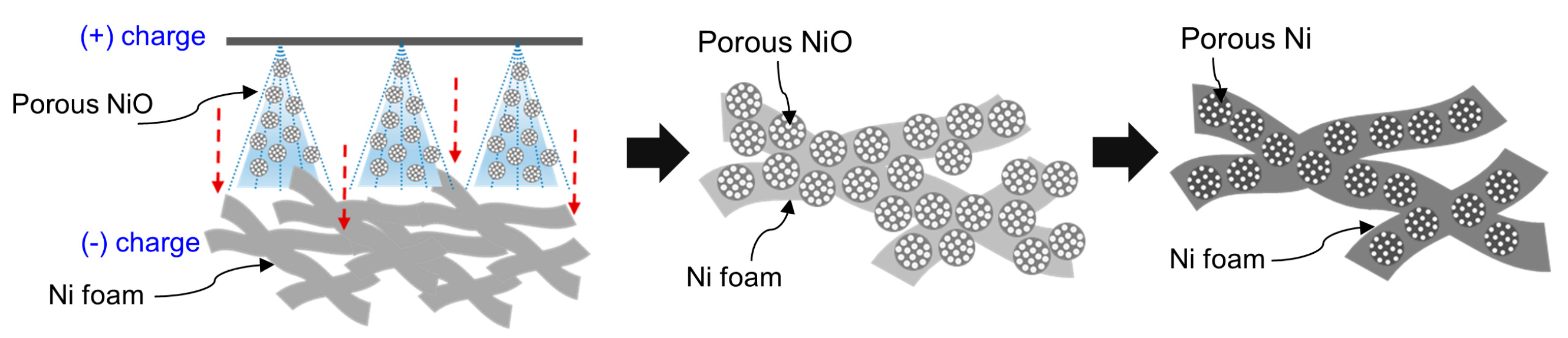
Figure 2.
SEM image of (a) Ni foam (ref), (b) porous NiO deposited Ni foam, and (c) porous Ni deposited Ni foam. (d) Enlarged image of porous Ni particles after reduction process.
Figure 2.
SEM image of (a) Ni foam (ref), (b) porous NiO deposited Ni foam, and (c) porous Ni deposited Ni foam. (d) Enlarged image of porous Ni particles after reduction process.
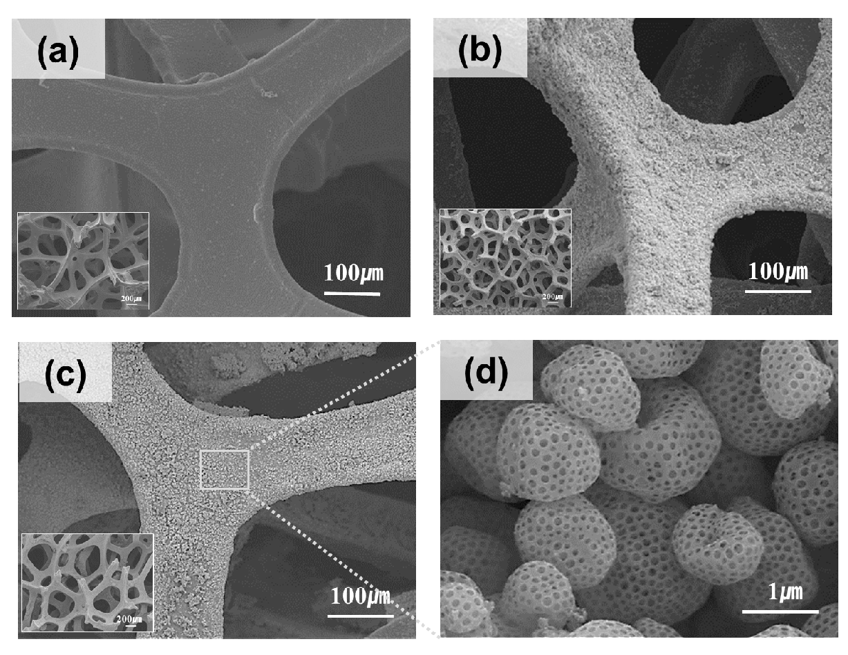
Figure 3.
(a) Desorption weight percent and (b) XRD pattern of porous Ni particles on Ni foam depending on reduction temperature at hydrogen atmosphere.
Figure 3.
(a) Desorption weight percent and (b) XRD pattern of porous Ni particles on Ni foam depending on reduction temperature at hydrogen atmosphere.
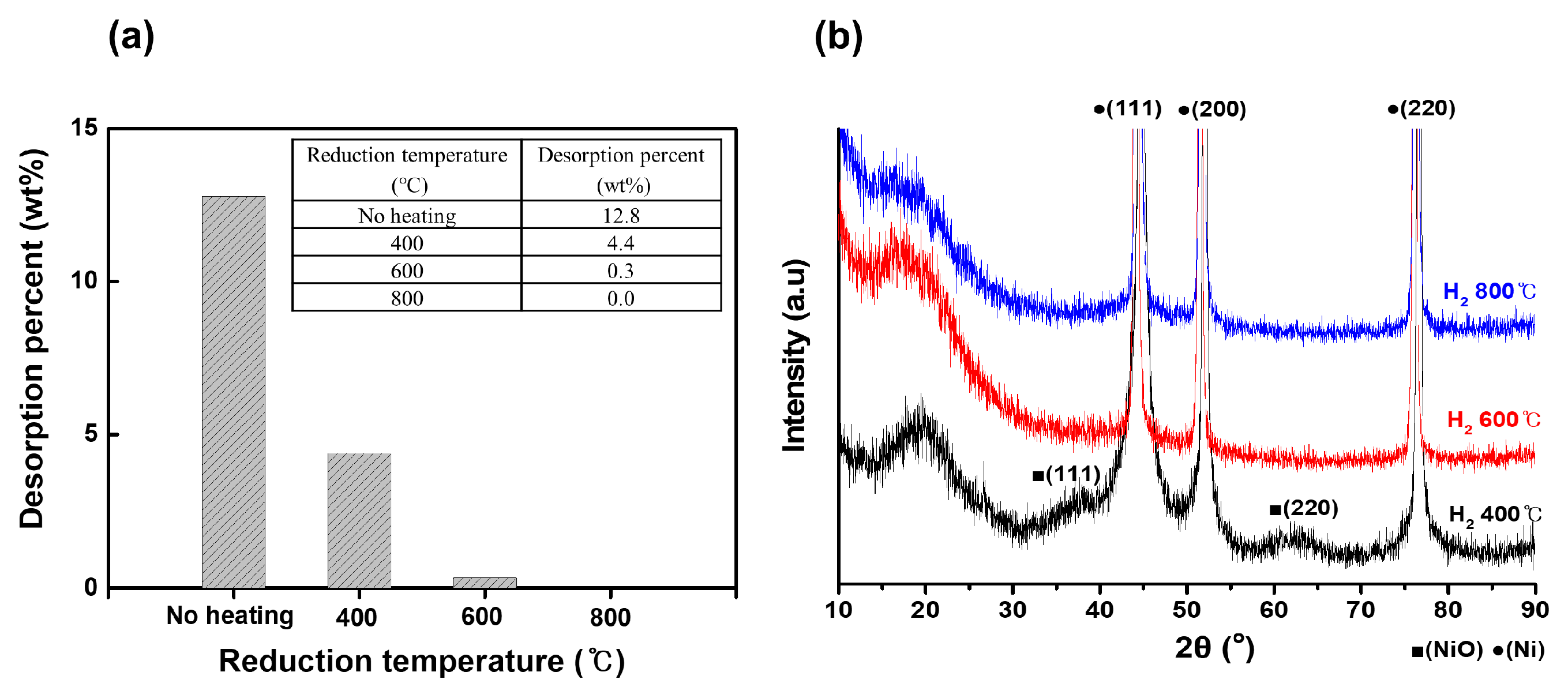
Figure 4.
XRD pattern for porous Ni oxide deposited on Ni foam (black) and porous Ni deposited on Ni foam (red) after reduction.
Figure 4.
XRD pattern for porous Ni oxide deposited on Ni foam (black) and porous Ni deposited on Ni foam (red) after reduction.
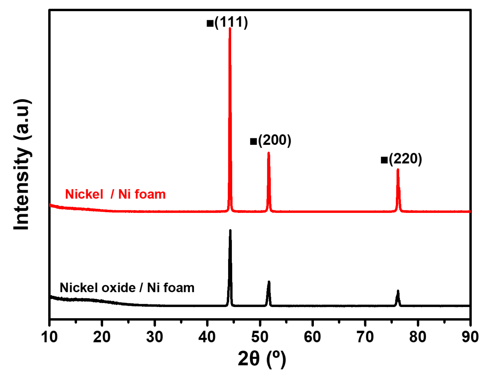
Figure 5.
XPS spectra of porous NiO, Ni, NiO-coated Ni foam, and Ni-coated Ni foam. (a) XPS intensity, (b) Ni 2p peak area (%), and (c) scheme of oxidation of samples.
Figure 5.
XPS spectra of porous NiO, Ni, NiO-coated Ni foam, and Ni-coated Ni foam. (a) XPS intensity, (b) Ni 2p peak area (%), and (c) scheme of oxidation of samples.
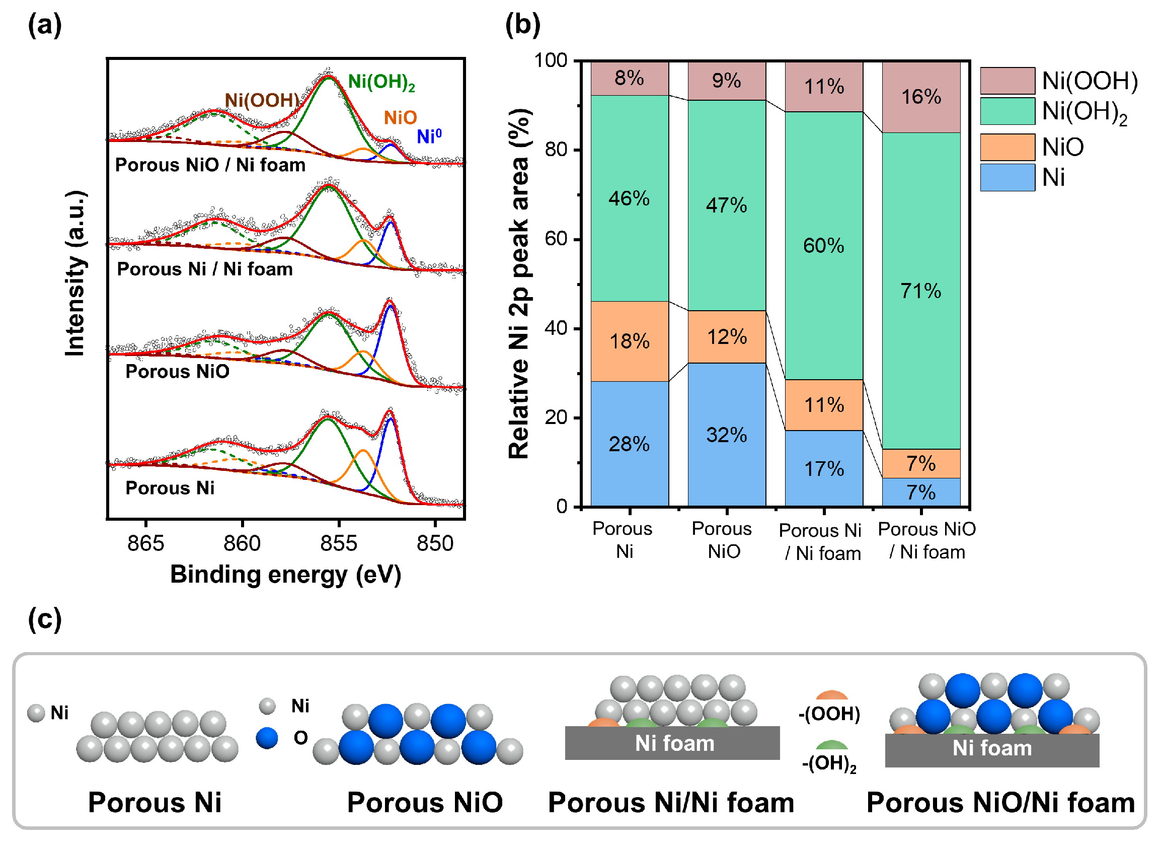
Figure 6.
1-Butene hydrogenation reaction at 100 °C: (a) 1-Butane conversion of Ni foam, porous Ni, and porous Ni-coated Ni foam; (b) turnover frequency of porous Ni and Ni-coated Ni foam; (c) scheme of Ni foam, porous Ni, and porous Ni-coated Ni foam.
Figure 6.
1-Butene hydrogenation reaction at 100 °C: (a) 1-Butane conversion of Ni foam, porous Ni, and porous Ni-coated Ni foam; (b) turnover frequency of porous Ni and Ni-coated Ni foam; (c) scheme of Ni foam, porous Ni, and porous Ni-coated Ni foam.
Disclaimer/Publisher’s Note: The statements, opinions and data contained in all publications are solely those of the individual author(s) and contributor(s) and not of MDPI and/or the editor(s). MDPI and/or the editor(s) disclaim responsibility for any injury to people or property resulting from any ideas, methods, instructions or products referred to in the content. |
© 2024 by the authors. Licensee MDPI, Basel, Switzerland. This article is an open access article distributed under the terms and conditions of the Creative Commons Attribution (CC BY) license (http://creativecommons.org/licenses/by/4.0/).
Copyright: This open access article is published under a Creative Commons CC BY 4.0 license, which permit the free download, distribution, and reuse, provided that the author and preprint are cited in any reuse.


