Preprint
Article

This version is not peer-reviewed.

Lead-Free Ceramics in Prestressed Ultrasonic Transducers

A peer-reviewed article of this preprint also exists.

Submitted:

22 January 2025

Posted:

24 January 2025

You are already at the latest version

Abstract

Todays ultrasonic transducers find broad application in diverse technology branches and most often cannot be replaced by other actuators. They are typically based on lead containing piezoelectric ceramics. These should be replaced for environmental and health issues by lead-free alternatives. Multiple material alternatives are already known, but there is a lack of information about their technological readiness level. To fill this gap., a small series of prestressed longitudinally vibrating transducers was set up with a standard PZT material and two lead-free variants within this study. The entire process for building the transducers is documented: Characteristics of individual ring ceramics, burn-in results, free vibration and characteristics under load are shown. The main result is that the investigated lead-free materials are ready to use within ultrasonic bolted Langevin transducers (BLT) for medium power applications, when the geometrical setup of the transducer is adopted. Since lead-free ceramics need higher voltages to achieve the same power level, the driving electronics or the mechanical setup must be altered specifically for each material. Lower self-heating of the lead-free materials might be attractive for heat sensitive processes.

Keywords: 
;  ;  

1. Introduction

Harmful and toxic substances should be avoided in products and manufacturing processes as far as possible. Besides health and environmental issues, a sustainable recycling of the products is desirable. Therefore, the strategic goal of a harmless and sustainable product design is the complete avoidance of toxic and environmentally harmful substances, e.g. heavy metals, which cause considerable problems in waste management. Against this background, the directive 2011/65/EU on the restriction of the use of hazardous substances in electrical and electronic equipment (RoHS) [1] regulates the use of substances like lead, mercury, chromium and others.
Hereby, ultrasonic technology is significantly affected, because the core component of almost all ultrasonic systems is the piezoelectric ceramic lead-zirconate-titanate (PZT). Due to the directive, many ultrasonic systems could be prone to restrictions in the foreseeable future. Lead-containing ultrasonic transducers must therefore be replaced by lead-free alternatives.
Ultrasonic technology is used in very different fields of application like industrial production (e.g. ultrasonic welding and ultrasonic cleaning), medical technology (e.g. ultrasound therapy and diagnostics, and surgical techniques), in the automotive sector (e.g. level and parking sensors), and in consumer goods (e.g. ultrasonic room humidifiers, ultrasonic knives). Accordingly, the requirements for ultrasonic transducers and thus for piezoelectric ceramics to be used in the various applications are very different. For this reason, various piezoelectric ceramics have been developed in the last century. By adjusting the chemical composition of the ceramics, the requirements for individual applications can be optimally met. For instance, the highest possible electromechanical coupling is wanted in the field of quasistatic actuators to achieve large stroke at low electrical input. Thermal stability is utmost important in the field of sensors. High dielectric coefficients are needed if much power needs to be converted in a low volume, which partially yields for the generation of underwater sound. A high mechanical quality factor is needed to achieve the highest possible vibration amplitudes in air.
Due to the high number of different applications and requirements, the development of lead-free substitute materials is challenging. With the increasing number of scientific publications on lead-free piezoelectric materials and upcoming commercially available lead-free materials, the pressure on ultrasonic system manufacturers to switch to lead-free ultrasonic transducers steadily increases. However, there is still little empirical knowledge regarding the application of lead-free ceramics in technical applications. One reason is that only a few ceramic manufacturers supply lead-free piezoelectric components such as discs or rings. The largest part of the available literature focuses on the composition and small-signal characteristics of various lead-free materials and their production on a laboratory scale. It should be kept in mind that it is a huge step and an extremely challenging task to scale the production of new materials from a laboratory scale to industrial production.
This study discusses medium power prestressed ultrasonic transducers with operating frequencies of commonly between 20-100 kHz, as they are used in processes like machining, cutting, cleaning, welding, etc. Some reports on the application of lead-free piezoelectric materials in prestressed ultrasonic transducers are discussed in the following.
Ref. [2] reports on a cleaning transducer with lead-free piezoceramics (bismuth-sodium-titanium-oxide-based composition). It is characterized by the fact that its oscillation speed drops less strongly at higher powers (up to 25 W) compared to a transducer with lead-containing ceramics, which is attributed to the reduced dependency of the oscillation quality of lead-free ceramics on the oscillation speed compared to PZT. Correspondingly, with the lead-free transducer, higher sound intensities could be achieved, which promises a better cleaning effect. The behaviour in continuous operation is not reported.
Ref. [3] presents a lead-free ultrasonic transducer which is used for a cutting tool. The used sodium-potassium-niobate (KNN) based materials have a higher vibration quality compared to PZT, which translates to a reduced self-heating of the ceramics. In addition, it is reported that their temperature behaviour is more stable (data not shown). The application tests of the ultrasonic knife showed no significant advantages or disadvantages of the lead-free material.
Ref. [4,5,6] report on different low to mid power ultrasonic transducers applied in ultrasonic wire-bonding applications. Ref. [4] deals with a BNT (bismuth-sodium-titanium-oxide) type leadfree ceramic. The authors come to the result that this ceramic is less dependent on mechanical prestress level than standard PZT. In Ref. [5] a significantly higher impedance of lead-free materials compared to PZT is highlighted. Concerning internal heating, electromechanical coupling factor, and stability in continuous operation, the results obtained from the reports seem quite promising for application of lead-free ceramics in wire-bonding applications.
The references mentioned above show that lead-free ceramics can certainly meet the challenges of use in power applications. However, the extent to which the used materials are "marketable" remains unclear, i.e. whether the used ceramics were laboratory prototypes or series products. At present, to the best of the authors knowledge, the ultrasonic cleaning transducer [7] described for the first time in [2] is the only prestressed ultrasonic transducer available on the market. Statements regarding the load behaviour, the temperature development, the reproducibility of the ultrasonic transducers and the long-term use have not been published yet.
The aim of this study is to test whether actual lead-free hard piezoelectric ceramics may be applied in prestressed ultrasonic converters of the common BLT type used in industrial and medical applications. A basic bolted Langevin transducer has been designed and built based on one lead-containing and two different lead-free ceramic materials (KNN based). Measurement results of the free vibrating transducers and under load are presented. They enable a direct comparison of the performance of prestressed ultrasonic transducers with lead-containing and lead-free piezo ceramics. The handling of the ceramics, the modelling, and the construction of transducers showed no special requirements for the use of lead-free ceramics. The transducers have all been built using identical metallic parts. This has been done intentionally to show up whether a one-by-one replacement of the PZT ceramics is feasible or not. In summary, similar results were achieved in large parts. This particularly applies for the power input into a water basin that was selected as the model load. Significant differences were found for the electrical voltage required during operation, which must be higher for lead-free materials due to their lower piezoelectric charge constant. Regarding self-heating, the lead-free materials showed advantages. For an optimal design of the transducers in terms of resonance frequency and bearing nodes, the geometry must be adapted to the specific material. This does not pose a major challenge based on common models.

2. Materials and Methods

Since piezoelectric ceramics are expensive, fragile and complex to machine compared to most metals, and have poor thermal conductivity properties, it has proven itself useful in ultrasonic technology to build transducers, which consist of a composite of several ceramics with metal parts. Brittle ceramics are usually pressure-resistant and tensile-sensitive. Since ultrasonic transducers are operated in resonance to achieve the greatest possible, defined movements at small electric field by resonance boost, it is necessary to preload the ceramics and thus reduce or completely avoid tensile stresses. The latter is particularly necessary if the individual components of the compound transducer are not additionally glued. This design was originally proposed by Paul Langevin [8] and is therefore commonly referred to as Bolted Langevin Transducer (BLT). More about this special design, its basic structure, modelling, design and operation can be found in a condensed form, for example, in [9].
Figure 1 shows the setup used in this study. This design has been chosen as the device under test, because it is typical for transducers of medium power used in medical technology, semiconductor manufacturing, and other application fields. The ultrasonic transducer consists of a prestress screw (①, ISO 14580, M5 x 20 mm, bore ∅ 2 mm, EN Titan Grade 5), five electrodes (②, ∅ 12.7 mm x ∅ 5.2 mm x 0.1 mm, EN CW 101 C), a backing mass (③, EN AW 7075), four piezoelectric ring ceramics (④, ∅ 12.7 mm x ∅ 5.2 mm x 2 mm), and a hollow base body (⑤, EN AW 7075) with a bearing collar (∅ 20 mm x 2 mm). The central channel is used for the optional supply or suction of process liquids, which can also be used to cool the transducer.
The aim of this study is to compare different hard piezoelectric materials for series production of prestressed ultrasonic transducers. To show the reproducibility of the ceramic rings, their electrical admittances at small signal excitation and free vibration have been measured immediately after delivery. 50 ceramic rings each, made of the lead-containing standard material (PIC 181) and two lead-free, KNN-based materials (PIC 758, PIC HQ2), were procured. They were clamped by two spring pins, which have little influence on the electromechanical coupling behavior and thus free vibration state is almost achieved. The measurement data was recorded PC-controlled by an impedance analyzer (HP 4192A, OSCL 50 mV). In addition, a finite element model was created for the ring ceramics (ANSYS 2024 R1), which was used to calculate frequency responses of the electrical admittance for the different materials using coupled field harmonic analysis.
Regarding the assembly of the transducers, prestress plays a key role. Typically, prestress limits the maximum of the achievable vibration amplitude. Thus, it should be as high as possible to prevent loosening of the screw connection or tensile stresses within the ceramics. Also, the applied prestress should be homogenous. Homogeneity and level of prestress influence the dynamic characteristics of the transducer: The resonance frequency increases with rising prestress due to increasing contact cross section [10]. Additionally, screw connections are subject to setting behavior, especially under dynamic load self-loosening might occur [11]. Besides these pure mechanical aspects, prestress also alters the characteristics of piezoelectric materials: Electrical, mechanical and piezoelectric coupling parameters change with prestress [12]. Too high prestress might lead to mechanical depolarisation. Additionally, the parameters change with waiting time after applying the prestress [13].
In summary, damping characteristics, resonance impedance and maximum achievable vibration amplitude of the transducer change with prestress and over time. Since they are important parameters for using the transducers in arbitrary applications, they should get “stabilized”. Typically, the prestress value is chosen to minimize resonance impedance or maximize vibration amplitude related to applied voltage, which both results in low damping. Once the right prestress level is found, the transducer is driven at high amplitude to accelerate mechanical setting and piezoelectrical aging. This process is widely common in high power ultrasound technology and named “burn-in-process”. Within this study, for each of the three materials, five transducers have been built and assembled with the same prestress of 40 MPa by measuring the generated charge (ATHENA Piezo Prestress Monitoring System [14]). Afterwards, the transducers have been continuously driven in mechanical resonance over a period of about 6 minutes at a vibration velocity amplitude of the transducer tip of about 1 m/s. This was achieved using a generator (ATHENA ultrasound generator [15]) enabling both, the tracking of the operating frequency and the regulation of the amplitude of the motional current. In resonance, motional current is directly proportional to the vibrator velocity. Within the generator, it is derived from the measured transducer current based on a lumped parameter approach ([16], equation 5). During the burn-in-process, electrical measurands as well as the vibration velocity amplitude of the transducer tip (Polytec OFV-5000-S high speed vibrometer) and the temperature of the piezoceramics (MICRO EPSILON thermometer LT-CF1-CB3) were logged. By evaluating those data for the five individual samples for each material, reproducibility of the manufacturing process can be assessed. As the design of the overall transducer and the manufacturing process has not been optimized yet, the characteristics will differ in a certain amount for transducers made with same ceramics.
To figure out the specific impact of the different materials on the vibration characteristics of the transducer, measurements at free vibration can give load-independent information: the current and voltage needed to generate a sufficient vibration amplitude indicate a kind of efficiency. The damping characteristics provide information about possible self-heating during continuous operation, and from parameter changes due to heat up the required cooling power can be derived. Important key figures like the resonance frequency fr, effective coupling keff (calculated from resonance and antiresonance frequency: k e f f 2 = ( f a 2 f r 2 ) / f a 2 ), and mechanical quality Qm (calculated based on 3 dB bandwidth: Q m = f r / f 2 f 1 ) are directly derived from admittance measurements. Electrical losses are small within hard piezoelectric ceramics and are neglected in this study. Piezoelectric coupling losses are hard to be separated from mechanical losses. As common for lumped parameter models of piezoelectric systems, these two non-electric losses are summed up in the mechanical damping factor. When the system is driven in mechanical resonance, the damping factor can directly be deduced from measured active power and vibration velocity: d = 2   P a c t i v e / v 2 . Small signal characteristics as well as electrical and mechanical quantities at high vibration levels were measured (ATHENA ultrasound generator) at room temperature and after self-heating by continuous operation at larger oscillating amplitudes. During resonance drive, the ATHENA ultrasound generator tracks the resonance based on a phase-locked loop algorithm and controls the amplitudes to predefined values based on the motional current amplitude irrespective of the actual acoustic load of the transducer.
To be able to assess the performance of the different transducers under load in continuous operation, the immersion of the transducer tip in water was chosen as the load because of its easy feasibility, reproducibility and relatively constant load. For this purpose, the ultrasonic transducer was clamped to its positioning collar and immersed vertically in a non-resonantly tuned water basin (PE, b x h x t = 160 mm x 220 mm x 140 mm) about 5 mm deep, see Figure 2. The ultrasonic transducers were water-cooled from the inside by using a pump (Modelcraft 3007, flow rate ≈ 500 ml/min) and operated by the generator at various target current amplitudes in a resonance-controlled manner. Electrical quantities and temperature were recorded. Figure 3 depicts the assembled series of transducers, the plastics clamping and the ATHENA ultrasound generator.

3. Results

3.1. Ring Ceramics at Free Vibration

Before assembling the ultrasonic transducers, the frequency response of the electrical admittance of the individual ceramic rings has been measured (HP4192A, 50 mV OSC). Figure 4 shows that sample scattering is relatively low for the standard material PIC 181 and the lead-free variants. Viewed individually, the resonance frequencies of the individual modes vary by less than 0.2 % from the respective mean value. This shows good reproducibility of the individual ceramic rings.
The simulation results by finite element modelling are based on the small signal parameters specified by the manufacturer for PIC 181 and PIC 758 [17,18]. For PIC HQ2, no complete material data set was available, so missing parameters were estimated iteratively using a simplified algorithm, leading to small deviations especially at higher frequencies. PIC HQ2 is a hard KNN-type material, which is experimentally modified to have a higher mechanical quality factor in comparison to PIC 758. However, the higher quality factor comes with the cost of lower d33.
Table 1 shows the material parameters used. The electromechanical behaviour of the ceramic rings is well represented by the model. The maximum amplitude in resonance and minimum amplitude in antiresonance determined in the simulation should not be overstated in this comparison, since the frequency discretization in simulation and measurement was not high enough to ensure an exact hit of the admittance tip. The larger deviations in measured vs. simulated PIC HQ2 curves show that there is still potential for optimization in the procedure for identification of material parameters.
The vibration shapes of the piezoelectric ceramic rings remain almost the same while resonance frequencies increase by about 35 % for PIC 758 and more than 60 % for PIC HQ2. Important parameters for application in transducers are Qm, k33 and d33. PIC HQ2 shows high Qm, but quite low d33 compared to PIC 181, while PIC 758 has relatively low Qm, but not too-a-low d33. Concerning k33 (sometimes used as a measure for the ability of energy conversion), the ceramics do not differ much. But all data are small signal parameters and might change significantly after prestressing and during large signal excitation.
Other authors [19,20] use metrics that allow material parameters to be used to estimate how well different materials are suited for the use in ultrasonic power applications. These are based on the idea that it is advantageous for power converters if the material has a large electromechanical coupling factor and a high vibration quality at the same time, which allows as much energy as possible to be converted in resonance and a low self-heating. If the highest possible vibration amplitudes are to be achieved, the product of coupling factor and vibration quality is preferred. The corresponding formulas and key figures are listed in Table 2.
Based on these key figures, it becomes clear that lead-free materials are clearly lagging lead-containing standard ceramics. The lead-free material PIC HQ2 (lower k33 and d33), which at first glance appears weaker in terms of electromechanical coupling, shows its advantages when the high vibration quality is considered. However, this is a particularly critical factor, as the vibration quality usually decreases significantly at high power [2,21], at least for PZT.

3.2. Results of the Burn-In Process

After assembly including prestressing, the transducers shown in Figure 3 were driven for 6 minutes in resonance at a constant velocity amplitude of 1 m/s (“burn-in process”).To ease the burden of reading and interpreting the results, the following figures will only show data for one representative transducer sample for each of the three different materials (more data available in the supplementary figures).
Figure 5 shows the data acquired during the burn-in-process. The temperature was pyrometrically measured directly on the piezoelectric ceramics. The figure shows the temperature rise over time, the relative change in the resonance frequency as a function of the temperature rise, the applied voltage related to the vibration velocity amplitude of the transducer tip over time and the ratio of the motional current and the vibration velocity amplitude of the transducer tip over temperature rise.
During the burn-in-process the transducers built with PIC 758 heated up more than the transducers with PIC 181 and PIC HQ2. The resonance frequency of PIC 181 and PIC HQ2 fell linearly proportional to the rising temperature. For PIC 758, this relationship was nonlinear. The ratio of voltage and velocity was significantly higher for the lead-free materials. The ratio of motional current and velocity stabilized over time and did not depend much on temperature for PIC 181 and PIC HQ2, while for PIC 758 this ratio dropped with increasing temperature even at the end of the burn-in process.

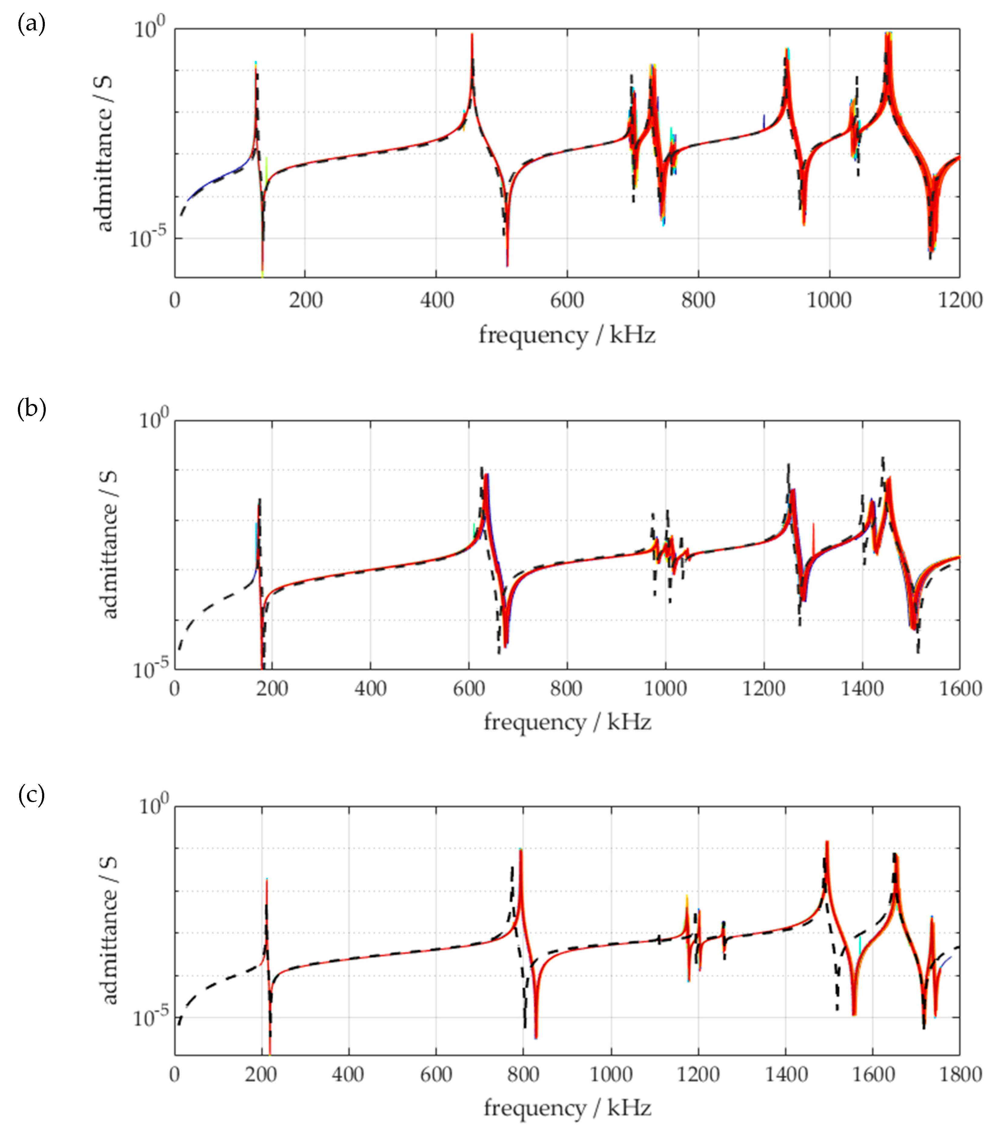
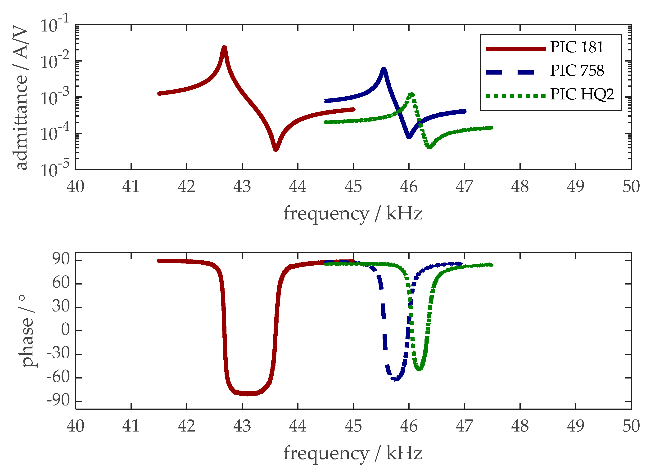
3.3. Characteristics of the Transducers at Free Vibration

Small signal admittance measurements have been made after the burn-in process for all individual transducers. Table 3 summarizes the results of the measurements for all individual transducers, Figure 6 shows the characteristics for the three representative transducers built with different materials.
Obviously, the transducers differ in resonance frequency fr: The lead-free variants have higher resonance frequencies due to lower density of the ceramics. Due to lower effective coupling keff and mechanical quality Qm, the phase drop between resonance and antiresonance is smaller for the lead-free transducers. While the standard deviation of resonance frequency and effective coupling is relatively low, the minimum impedance Zmin and the quality factor Qm show a higher standard deviation for all materials.
Figure 7 shows results of tests in which the transducers were first driven in resonance with a slowly increasing nominal amplitude up to the maximum motional current corresponding to a transducer tip oscillation velocity of about 1.5 m/s. This nominal state was held for several minutes, until a self-heating of about 30 K had been observed. The relationship between the motional current and the velocity amplitude of the transducer tip, the mechanical damping constant of the transducer determined from the electrical active power and the velocity amplitude as a function of the velocity amplitude of the transducer tip, the ratio of the motional current and velocity amplitude of the transducer tip as a function of the heating and the mechanical damping constant as a function of the temperature are plotted.
The ratio of motional current and ”Ibra’Ion velocity is constant for all materials until the maximum speed is reached. The amount of motional current of transducers with lead-free materials is lower than that of transducers with lead-containing material due to their lower d33 value. The temperature has not risen significantly until reaching maximum speed. While the maximum target current amplitude is maintained, the temperature increases and the ratio of motional current to vibration velocity changes. The ratio increases by about 10 % for PIC 181 and PIC HQ2 and remains constant for PIC 758 until about 10 K temperature rise and then falls by about 10 %. The mechanical damping factor determined from the measured active power and vibration velocity changes depending on the vibration velocity and temperature: While this factor drops for all materials up to a vibration amplitude of about 1 m/s, it rises above this value for PIC 181 and 758, while it falls for PIC HQ2. At a speed of about 1.5 m/s, the mechanical damping factor (d = 2*Pw/v2) of PIC 181 increases linearly with temperature, with PIC 758 it remains somewhat constant until a temperature of about 10 K and then decreases; with PIC HQ2, the damping factor drops slightly over the entire temperature range. The damping factors of the transducers differ in a range of approximately factor 2. Remarkably, PIC HQ2 has the lowest power requirement.

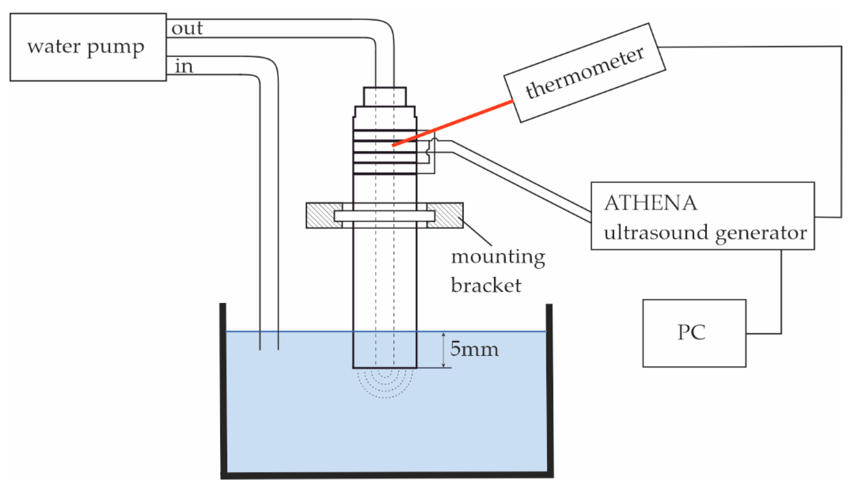
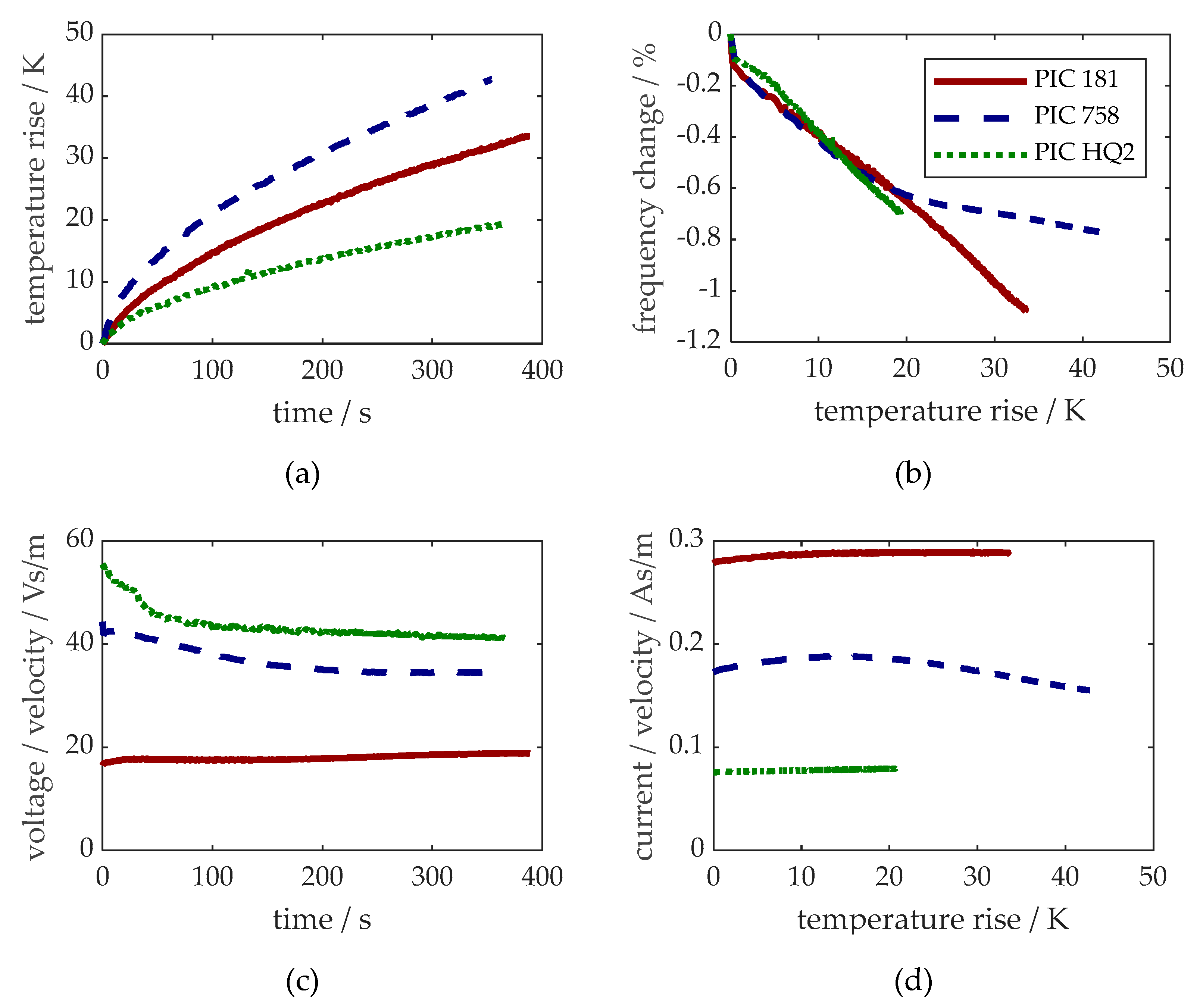
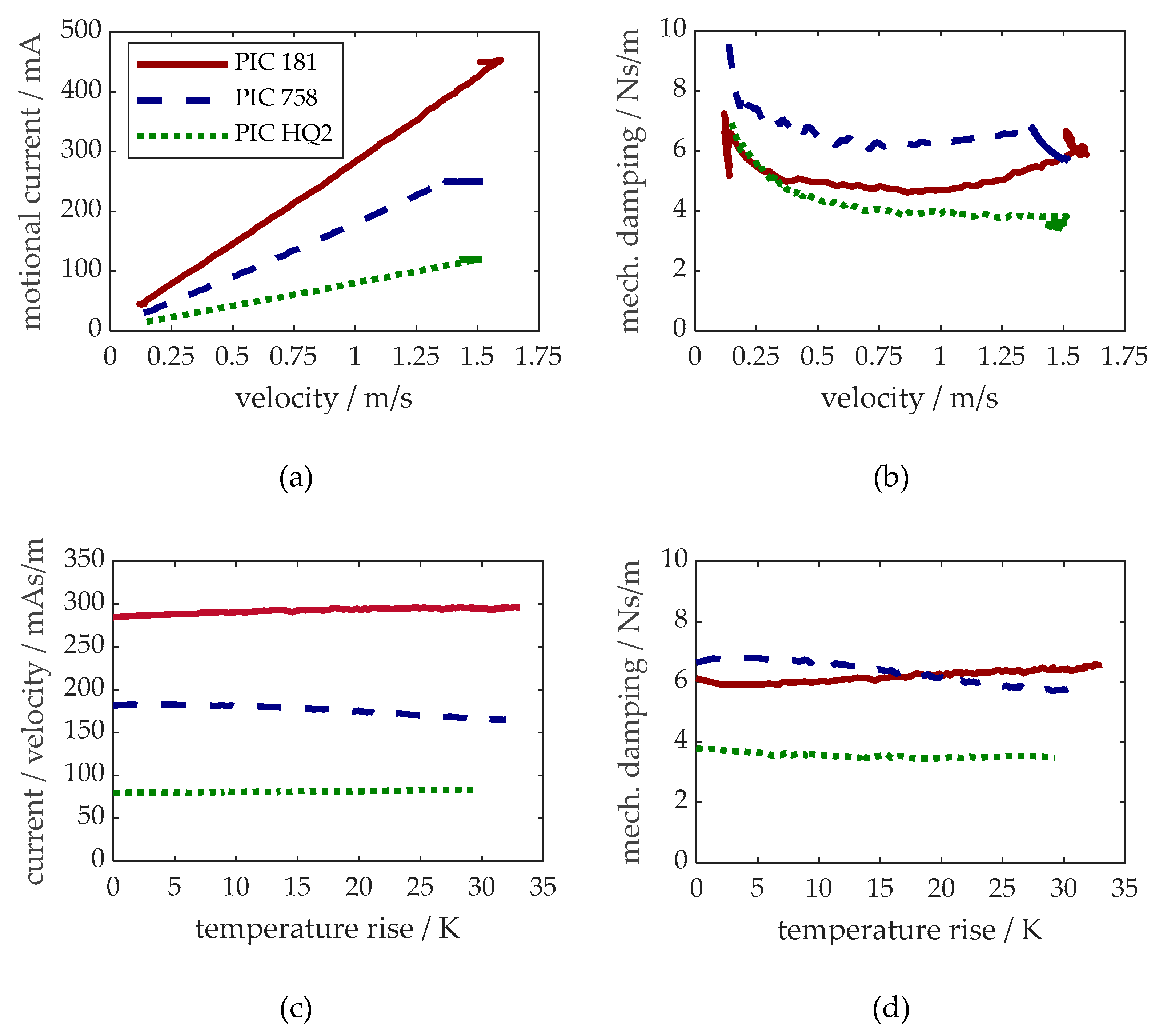
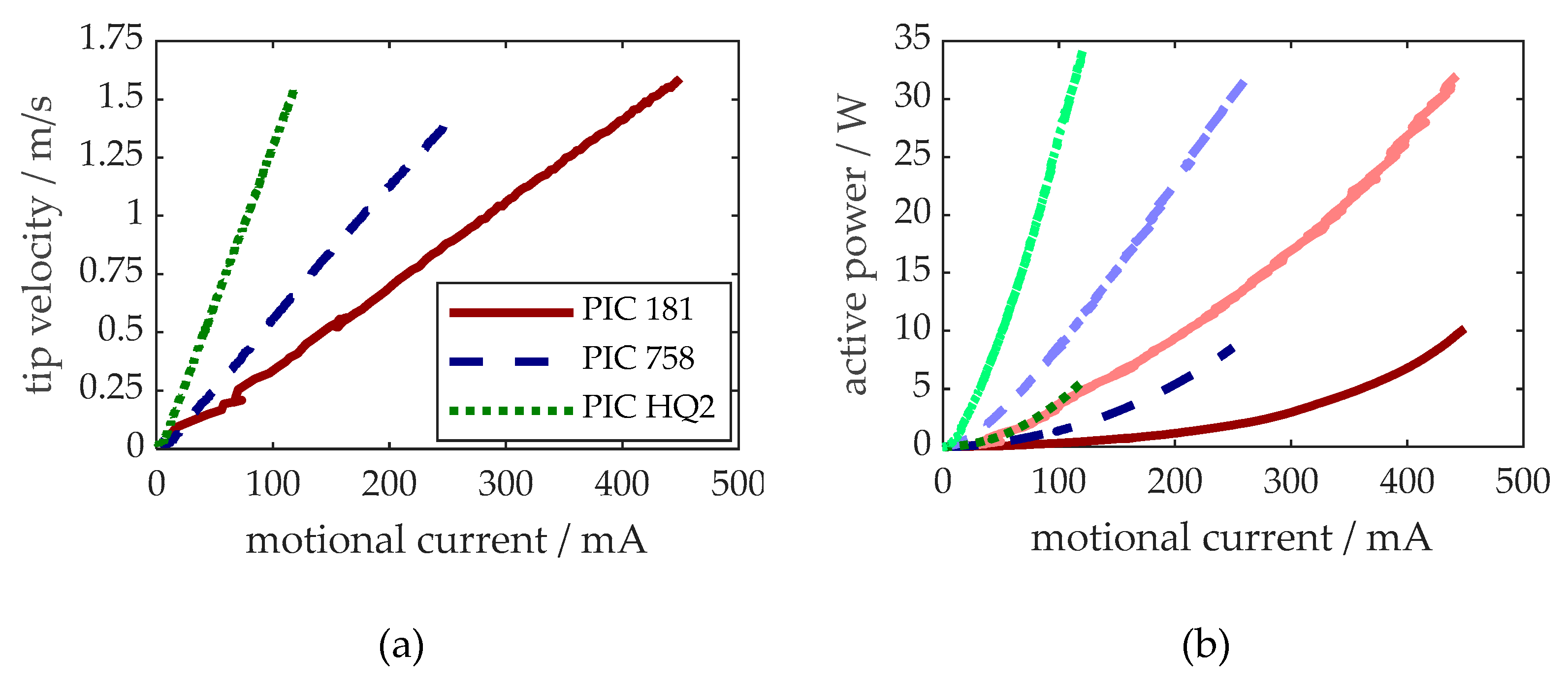
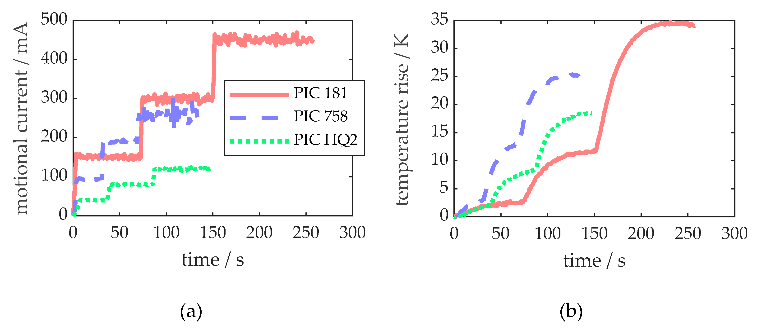
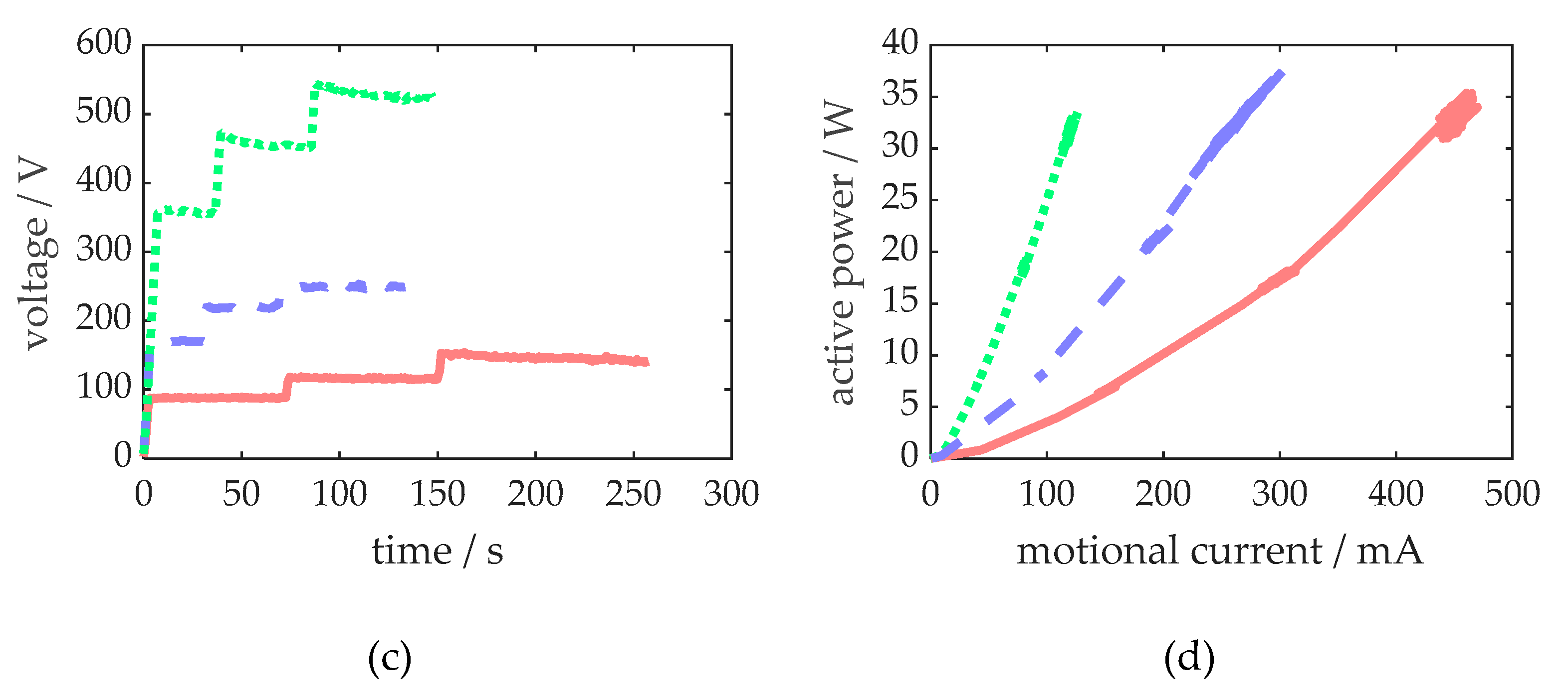
3.4. Characteristics Under Load

Figure 8 shows the results of short-time operation tests with the various ultrasonic transducers without and with load, which were carried out in a clocked mode to prevent heat up of the transducers. The velocity of the transducer tip at free oscillation as a function of the motional current, which was specified as a control variable, and the active electrical power in the free and immersed state as a function of the motional current are shown.
As already depicted in Figure 7, at room temperature, the tip velocity linearly depends on motional current for all transducers. Here, the dependency of these quantities is shown again to proof its validity even for the transducers vibrating without load but being clamped in a plastic bearing, which was also used within the load tests.
At free oscillation with an amplitude of 1.5 m/s, the transducers with PIC HQ2 require only about 6 W active power, while the transducers built with PIC 758 and PIC 181 require about 9 W and 10 W, see Figure 8 (b). Under load, the transducers consume between 32 W and 34 W at the highest amplitude of their individual motional current.
The results of the load test including heat up of the transducers are shown in Figure 9. The required voltage is higher for the lead-free materials. The transducers built with PIC 181 generate more heat than those with the lead-free materials, while active power reaches about the same level irrespective of the different materials.

4. Discussion

The admittance measurements of individual piezoelectric ceramic rings showed that their production process is highly reproducible and that the dispersion of individuals is in the usual range. It needs some further investigation to achieve precise material data for the newest material developments (in this case PIC HQ2), but there is no doubt that existing models will also cover their characteristics. The main differences between PZT PIC 181 and the lead-free variants PIC 758 and PIC HQ2 are the much lower density (about 40 %), lower dielectric constants and somewhat lower piezoelectric coupling of the lead-free ceramics. These lead to higher resonance frequencies and lower distance of resonance and anti-resonance frequencies as well as lower currents, but higher voltages at given output velocities.
Although the materials are quite different concerning their acoustic properties, the resonance frequency of the BLT, being built within this study based on the same metallic parts for all material variants, does not vary by more than 10%. The reason for this behaviour is the large volume fraction of metallic parts in the built transducer. It largely defines the distributions of elasticity and mass. For systems which contain more piezoelectric material or transducers that must be driven at a fixed frequency, this might be an issue for the replacement of PZT by lead-free variants. Additionally, the different piezoelectric materials do alter the position of the vibrational node. Thus, the bearing collar is not placed ideally for all the transducers, which might have led to increased losses while driving the transducers being clamped in the plastics bearing. To prevent this, the position of the bearing should be adapted when using lead-free piezoelectric ceramics. This change in geometry needs some extra effort in the design of the transducer, but using today’s standard calculation tools, this should not be a real hurdle at integrating lead-free ceramics. Nevertheless, precise material parameters are required within the design process.
Over-all, lead-free materials show similar behaviour during burn-in: Characteristics, which are important for the controlled use of the transducers in arbitrary processes, like resonance frequency, minimum impedance, and the ratio of motional current and vibration velocity stabilize (as far as temperature effects are avoided). Thus, the burn-in remains an important step in producing transducers, even using lead-free ceramics.
The comparison of the free vibrating transducer characteristics after burn-in shows, besides the higher resonance frequency of the lead-free transducers, that a lower admittance-level (or higher impedance) in the order of up to one magnitude is another important difference in the behaviour of the materials. This can be affording for the driving electronics (e.g. being tuned to a 50 Ohm load) or control algorithms (small current values might be an issue in measuring phase of current and voltage, which is needed for phase-locked-loop-control). If high power is needed, the lead-free transducers must be driven at higher voltage. Alternatively, thinner ceramics could be used to achieve sufficient electric field strength. Due to the lower piezoelectric coupling – more volume of piezoelectric material might be needed. This is important to be considered during the design of new transducers with lead-free piezoelectric ceramics or for the adaption of existent transducers based on PZT. Additionally, quite large deviation of minimum impedance Zmin and quality factor Qm in the order of 10-30 % indicates that the design and the manufacturing process including prestress should be optimized.
The ratio of motional current and tip velocity is important to control the vibration amplitude in processes without measuring it directly but adjusting the motional current. Driving the transducers resonance controlled with and without temperature rise showed that this ratio depends on temperature for all materials. While PIC 181 and PIC HQ2 need additional current to maintain the same velocity, PIC 758 needs less current with increasing temperature. This is an interesting effect, which could be investigated in detail, but being limited to about 10 % at a 30 K temperature rise could also be neglected if control must not be highly precise. If the temperature is kept constant (e. g. by driving the water-cooled transducers with short pulses), motional current and tip velocity are directly proportional and thus, controlling the motional current amplitude coincides with controlling vibration amplitude.
Another interesting observation made during free vibration of the transducers is the fact that mechanical system damping increases with PIC 181 and PIC 758 at higher vibration amplitudes while PIC HQ2 shows a decrease. That fits well to the observations in other publications, e.g. [2]. In this study, the transducers build with PIC HQ2 showed the lowest damping factors and – in good correlation – the lowest heat up during continuous drive: Driving the transducers under load until reaching steady state temperature showed that temperature rise of the transducers built with lead-free materials is lower than that of the transducers with standard material. PIC 758 showed larger mechanical damping at room temperature than PIC 181, which relates well to their difference in mechanical quality factor, but at higher temperatures damping in PIC 758 reduces, which finally results in lower heat up than PIC 181. This might make lead-free materials interesting for processes where heat-up cannot be prevented. On the other hand, it was observed during cooling down the transducers after use, that thermal conductivity of the lead-free materials must be smaller, as it took more time for them to cool down at the same cooling condition.
Using the appropriate motional current amplitudes in resonance, the transducers built with the different ceramics could all be continuously driven at the desired velocity amplitude of 1.5 m/s in water. Strong cavitation activities were recognised during this state, and the overall real power needed was in the range of roundabout 30 W for all three materials. This is because the greatest amount of power in a well-designed transducer is acoustically transferred to the load (about 22.5 W at 1.5 m/s for the geometry used here). Scattering in these results might be produced by varying clamping conditions, power transfer to the attached hose and to the cooling water running through the transducer, as well as load fluctuation by strong cavitation which produces a mix of liquid and bubbles in front of the transducer. With PIC 758, active power might even be higher because stronger vibration was generated than with the two other materials due to the slightly varying relation between motional current (which was held constant during the experiments) and output velocity. The stronger heating of PIC 758 during the burn-in process might also be attributed to this effect.

5. Conclusions

The aim of this study was to test whether actual lead-free piezoelectric ceramics may be applied in prestressed ultrasonic converters of the common BLT type used in industrial and medical applications. Two different lead-free KNN-based piezoelectric materials have successfully been integrated into a standard BLT. Regarding medium power output, internal heating, reproducibility and mid-time stability, the results were quite good compared to the lead-containing standard. The main challenges for the future (except for cost of new materials) result from lower electromechanical coupling (described by the material parameters d33 and k33). This leads to the need of applying a stronger electrical field which might limit the obtainable power output in high-power applications.
Nevertheless, lead-free materials cannot replace PZT one by one: To meet requirements as fixed frequency, given electrical impedance or generating larger power amount, the geometry of the transducers must be adapted. Supplementary, it is an important result that small signal data of the leadfree ceramic types could be applied for Finite Element calculations as well-known from dealing with lead-containing PZT ceramics. Predictability and reproducibility of the new material’s properties have reached a high level during the past few years.

Supplementary Materials

The following supporting information can be downloaded at: Preprints.Org.

Author Contributions

All the results have been achieved in close cooperative work of all the authors, there has been no clear separation into single tasks. All authors have read and agreed to the published version of the manuscript.

Funding

This Project has been supported by the Federal Ministry for Economic Affairs and Climate Action (BMWK) on the basis of a decision by the German Bundestag, grant number KK5011523AB3.

Data Availability Statement

All data are given in the figures. Please contact one of the corresponding authors in case of further request.

Acknowledgments

The authors gratefully acknowledge the support of PI Ceramics who supplied the materials used for experiments.

Conflicts of Interest

The authors declare no conflicts of interest. The funders had no role in the design of the study; in the collection, analyses, or interpretation of data; in the writing of the manuscript; or in the decision to publish the results.

References

  1. Directive 2011/65/EU of the European Parliament and of the Council of 8 June 2011 on the restriction of the use of certain hazardous substances in electrical and electronic equipment. EUR-Lex Document 02011L0065-20240801. Available at http://data.europa.eu/eli/dir/2011/65/2024-08-01.
  2. Tou, T.; Hamaguti, Y.; Maida, Y.; Yamamori, H.; Takahashi, K.; Terashima, Y.: Properties of Lead-Free Piezoelectric Ceramics and Its Application to Ultrasonic Cleaner. Proc. Symp. Ultrasonic Electronics, 2008, 29, pp. 363-364. [CrossRef]
  3. Akca, E., Yilmaz, H.: Lead-free potassium sodium niobate piezoceramics for high-power ultrasonic cutting application: Modelling and prototyping. Proc. and Appl. of Ceramics, 2019, 13-1, pp. 65-78. [CrossRef]
  4. Mathieson, A.; DeAngelis, D. A.: Analysis of Lead-Free Piezoceramic-Based Power Ultrasonic Transducers for Wire Bonding. IEEE UFFC, 2016, 63-1, pp. 156-164. [CrossRef]
  5. Chan, H. L. W., Choy, S. H., Chong, C. P., Lo, H. L., Liu, P. C. K.: Bismuth sodium titanate based lead-free ultrasonic transducer for microelectronics wirebonding applications. Ceramics International, 2008, 34, pp. 773-777. [CrossRef]
  6. Kwok, K. W.; Lee, T.; Choy, S. H.; Chan, H. L. W.: Lead-free piezoelectric transducers for microelectronic wirebonding applications. In: Piezoelectric Ceramics. Ed. Ernesto Suaste-Gomez, IntechOpen Limited: London, United Kingdom, 2010, pp. 145-164. [CrossRef]
  7. Lead-free bolt-clamped Langevin type transducer. Available online: https://en.honda-el.co.jp/product/ceramics/lineup/lead_off/lead-off, accessed on 18-10-2024.
  8. Langevin, P.: Method and apparatus for transmitting and receiving submarine elastic waves using the piezoelectric properties of quartz. French Patent Office, 1918, Patent no. FR505703.
  9. Hemsel, T., Twiefel, J.: Piezoelectric Ultrasonic Power Transducers. In: Encyclopedia of Materials: Electronics. Academic Press, Oxford, United Kingdom, 2023, pp. 276-285. [CrossRef]
  10. Arnold, F.J., Mühlen, S.S.: The Influence of the thickness of non-piezoelectric pieces on pre-stressed piezotransducers. Ultrasonics, 2003, 41-3, pp. 191-196. [CrossRef]
  11. Friede, R., Lange, J.: Self loosening of prestressed bolts. Nordic Steel Construction Conference, 2009, pp. 272-279, available at https://www.researchgate.net/publication/237651813_Self_loosening_of_prestressed_bolts.
  12. Audigier, D., Richard, Cl., Descamps, Cl., Troccaz, M., Eyraud, L.: PZT uniaxial stress dependence: experimental results. Ferroelectrics, 1994, 154-1, 219–224. [CrossRef]
  13. Yang, G., Liu, S. F., Ren, W., Mukherjee, B. K.: Effects of uniaxial stress on the piezoelectric, dielectric, and mechanical properties of lead zirconate titanate piezoceramics. Ferroelectrics, 2001, 262-1, 207–212. [CrossRef]
  14. ATHENA Technologie Beratung GmbH: Description of piezo prestress monitoring system, available online: http://shop.myathena.de/epages/12074748.sf/de_DE/?ObjectPath=/Shops/12074748/Products/AM100, accessed on 13-01-2025.
  15. ATHENA Technologie Beratung GmbH: Description of ultrasound generator, available online: http://shop.myathena.de/epages/12074748.sf/de_DE/?ObjectPath=/Shops/12074748/Products/AM200, accessed on 13-01-2025.
  16. Littmann, W., Hemsel, T., Kauczor, C., Wallaschek, J., Sinha, W.: Load-adaptive phase-controller for resonant driven piezoelectric devices. Proceedings of World Congress Ultrasonics, 2003, pp. 547-550.
  17. Complete material data set PIC 181, available on request.
  18. PI Ceramic Material Data, available online: https://www.piceramic.com/fileadmin/user_upload/physik_instrumente/files/datasheets/PI_Ceramic_Material_Data.pdf, accessed on 18-10-2024.
  19. Li, X.; Fenu, N. G.; Giles-Donovan, N.; Cochran, S.; Lucas, M.: Can Mn:PIN-PMN-PT piezocrystal replace hard piezoceramic in power ultrasonic devices? Ultrasonics, 2024, 138. [CrossRef]
  20. Ringaard, E.; Levassort, F.; Wang, K.; Vaitekunas, J.; Nagata, H.: Lead-Free Piezoelectric Transducers. IEEE UFFC, 2024, 71-1, pp. 3-15. [CrossRef]
  21. Nguyen, T. N.; Thong, H.-C.; Zhu, Z.-X.; Nie, J.-K.; Liu, Y.-X.; Xu, Z.; Soon, P.-S.; Gong, W.; Wang, K.: Hardening effect in lead-free piezoelectric ceramics. J. Mat. Res., 2021, 36-5, 996-1014. [CrossRef]
Figure 1. BLT design: The backing mass (③), 4 piezoelectric ceramic rings (④) and 5 electrodes (②) are prestressed by a hollow screw (①); the base body (⑤) has an internal thread at its front side to attach a sonotrode (not used within this study).
Preprints 146964 g001
Figure 2. Experimental setup: Structure of the actuator in a loaded state (immersed in water) and its electrical control, with a schematic representation of the water circuit and non-contact measurement of the surface temperature of the piezo elements.
Preprints 146964 g002
Figure 3. Series of assembled transducers with PZT and lead-free piezoelectric ceramics, plastics mounting bracket, and ATHENA ultrasound generator being used for resonance-controlled operation and measurements.
Preprints 146964 g003
Figure 4. Measured frequency responses of the short-circuit input admittance of 50 individual ring ceramics (coloured solid lines) compared to simulation results (dashed black line) for (a) PIC 181, (b) PIC 758, (c) PIC HQ2. Please remark the different frequency ranges used in the diagrams for convenience.
Preprints 146964 g004
Figure 5. Results of the burn-in process (free resonant vibration at ≈ 1 m/s for ≈ 6 minutes), : (a) Temperature rise over time, (b) resonance frequency change over temperature rise, (c) voltage related to tip velocity over time, (d) motional current related to tip velocity over temperature rise.
Preprints 146964 g005
Figure 6. Small signal admittance characteristics (free vibration, room temperature).
Preprints 146964 g006
Figure 7. Results of tests (resonance controlled continuous vibration up to 1.5 m/s, heat up over time): (a) Dependency of tip velocity and motional current, (b) mechanical damping factor over tip velocity, (c) ratio of motional current and tip velocity over temperature rise, and (d) mechanical damping factor over temperature rise.
Preprints 146964 g007
Figure 8. Results of short-time operation tests, colours stand for different materials (PIC 181: green, PIC 758: red, PIC HQ2: blue): (a) Dependency of tip velocity and motional current for no-load vibration of the transducer being fixed in the clamping, and (b) active power over motional current at free vibration (dark colours) and under water load (light colours).
Preprints 146964 g008
Figure 9. Results of the load tests with heat up (immersion of the transducer tip into water, controlled vibration at different levels of motional current, continuous drive until steady state temperature): (a) motional current amplitude over time, (b) temperature rise over time, (c) voltage amplitude over time, and (d) active power over motional current amplitude.
Preprints 146964 g009aPreprints 146964 g009b
Table 1. Material data of the piezoceramics.
Material PIC 181 [17] PIC 758 [18] PIC HQ2
ρ / kg / m 3 7850 4800 4800
Q m 2200 585 2500
ε 11 T / ε 0 1224 950 254
ε 33 T / ε 0 1135 850 228
e 31   / N / Vm -4.5 -2,6 -2.2
e 33   / N / Vm 14.7 12.6 7.0
e 15   / N / Vm 11.0 9.0 3.3
c 11 E   / 10 10 N / m 2 15.20 15.16 19.00
c 12 E   / 10 10 N / m 2 8.91 6.83 6.00
c 13 E   / 10 10 N / m 2 8.55 8.15 8.20
c 33 E   / 10 10 N / m 2 13.10 14.63 19.45
c 44 E   / 10 10 N / m 2 2.83 3.15 3.00
k 33 0.66 0.57 0.50
d 33   / 10 - 12 m / V 253 170 60
Table 2. Material data of the piezoceramics.
Key figure PIC 181 PIC 758 PIC HQ2
k 33 2 Q 958 190 625
d 33 Q   / 10 - 9 m / V 557 100 150
Table 3. Results deduced from small signal admittance measurements on all individual transducers. Standard deviation was calculated based on small series of five transducers for each material.
PIC fr Zmin keff Qm
kHz σ / % Ohm σ / % - σ / % - σ / %
181 42.68 0.31 43.66 8.67 0.21 0.23 766 8.73
758 45.43 0.42 136.36 29.62 0.14 1.23 722 24.61
HQ2 45.94 0.52 775.86 23.04 0.12 1.63 533 16.08
Disclaimer/Publisher’s Note: The statements, opinions and data contained in all publications are solely those of the individual author(s) and contributor(s) and not of MDPI and/or the editor(s). MDPI and/or the editor(s) disclaim responsibility for any injury to people or property resulting from any ideas, methods, instructions or products referred to in the content.
Copyright: This open access article is published under a Creative Commons CC BY 4.0 license, which permit the free download, distribution, and reuse, provided that the author and preprint are cited in any reuse.
Prerpints.org logo

Preprints.org is a free preprint server supported by MDPI in Basel, Switzerland.

Subscribe

Disclaimer

Terms of Use

Privacy Policy

Privacy Settings

© 2025 MDPI (Basel, Switzerland) unless otherwise stated