

Submitted:
10 December 2024
Posted:
11 December 2024
You are already at the latest version
Abstract
Plants, in particular trees, derive energy to raise soil water to a height of many tens of meters by means of the phenomenon of transpiration. The development of the first two-stream artificial transpiration devices, started in recent years, becomes a motivating incentive for studying ways to turn such devices into energy sources of a new type. There is a prospect of using not only gravitational property of water, which allows to extract energy with the help of water wheels, dams and hydro stations, but also two molecular properties of water (property to create surface tension and property to evaporate easily), which manifest themselves in the phenomenon of transpiration and have not yet found application in the processes of technical energy production. The paper is devoted to a special analysis of the role played by molecular properties of water in two-stream artificial transpiration device and the issues of using such device as energy generator. Three typical models of device capable of performing the functions of an energy generator using molecular properties of water are proposed. The amount of energy generated by the devices in autonomous mode is estimated in the range from fractions of a watt to tens of kilowatts.
Keywords:
transpiration
; artificial transpiration devices
; evapotranspiration
; clean energy
Introduction
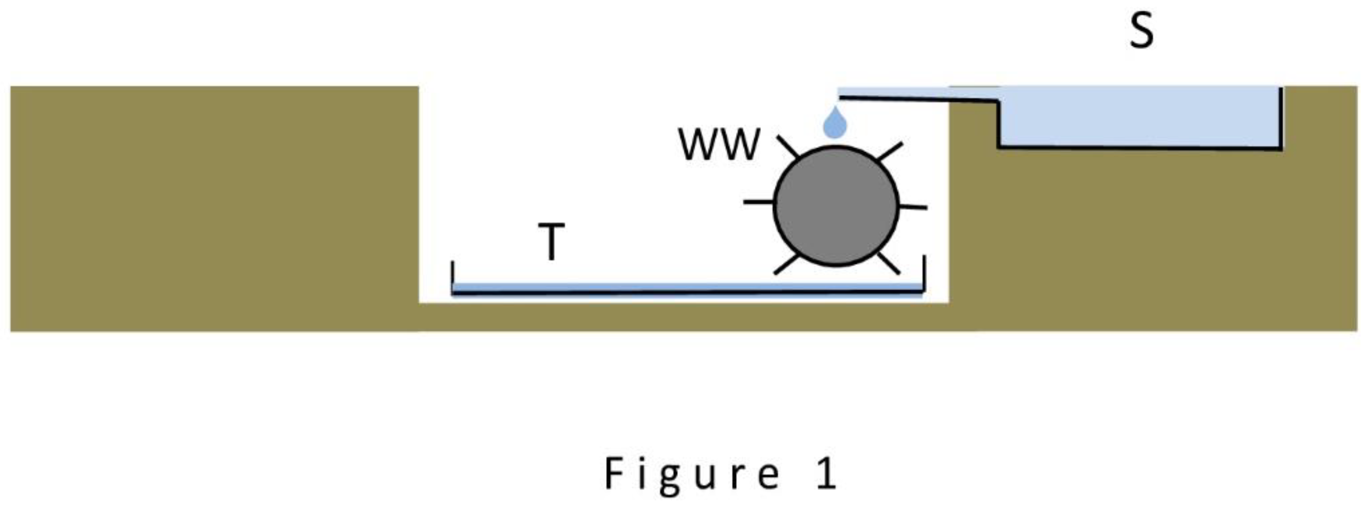
This paper focuses on problems of energy generation through the use of both gravitational and two molecular (hereinafter referred to as subtle) properties of water: the property to create surface tension and the property to evaporate easily. In conducting the briefest review of the role of water as a source of energy in the world of man and nature, the following three circumstances can be identified as important from the point of classifying the ways in which energy is produced. The first circumstance is that man remains focused exclusively on the use of the gravitational property of water, on the creation of hydraulic structures (water wheels, dams, hydro stations), obtaining with their help about one sixth of the energy produced on the planet today. The second circumstance is found in the world of plants: here, exclusively the two marked subtle properties of water are used to obtain energy. Both of these properties are actively manifested in the phenomenon of transpiration found in every plant. In recent years [1], the total amount of energy produced by planet’s plants (mainly trees) in the process of transpiration has been taken into account - this amount turns out to be huge, comparable to the amount of energy produced by all hydro stations built by man. It turns out that the amount of energy obtained by using water by man and plants is almost the same. The third circumstance is that both man and plants did not pay attention the option of using simultaneously the gravitational property of water and one of mentioned subtle properties: the property to evaporate easily into the atmosphere. Figure 1 shows a diagram explaining the essence of this option by a simple example. The Figure 1 shows a water wheel WW, capable of generating energy if three conditions are met: the presence of a water source S on the surface of the earth that supplies water to the blades of the wheel; the presence of a hollow in the earth near the source in which the wheel is placed; and the presence at the bottom of the hollow of a large flat tank T for water flowing off the wheel, simultaneously acting as an evaporator of the incoming water into the atmosphere. The presented diagram differs from hydraulic diagrams of the usual type (for example, from a dam with a water wheel) only by the fact that for drainage of water used by the water wheel not the usual drainage of this or that design is used, but an evaporator removing water to the atmosphere (in this simplest case the role of the evaporator is performed by the tank T itself). Further considerations in the course of the article will show that this variant of energy generation is worthy of practical attention, despite its low, at first glance, productivity.
The three given circumstances suggest the following simple classification of the ways of energy generation involving water:
way to use only the gravitational property of water;
way to use two subtle properties of water (property to create surface tension, property to evaporate);
way to use the gravitational property and the property to evaporate;
way to use all three properties of water.
Within this classification, only the first of these ways is used by man to produce energy on an industrial scale. From the above it follows that at least the same amount of energy can be obtained by using the other three ways if they are practically realized. The last sentence serves as a convincing argument in favor of a carefully studying these ways and determining the prospects for creating new sources of environmentally friendly energy based on them.
There is almost no information in the scientific literature about attempts to use the subtle properties of water to create energy sources and to realize in practice the second, third, and fourth ways of energy generation (the only mention of the problem is contained in [2] in a hypothetical form). This paper is the first attempt to fill this gap, to clarify and analyze the technical problems that stand in the way of creating energy sources based on the subtle properties of water, and to identify ways to solve these problems.
The paper is organized as follows. The first part is devoted to a special analysis of the role of subtle water properties in two-stream artificial transpiration devices. In the course of the analysis the answers to the following two questions are sought: due to what process does the gain in energy occur in such devices and what formula estimates the amount of the gained energy. In the second part a comparative analysis of the second, third and fourth ways of energy generation according to the classification proposed here is given. In essence, this part is a review of the work done to design the simplest models of energy generators that utilize, in various combinations, the three mentioned properties of water (the gravitational property and the two subtle properties), and finally, proposes three models (hereinafter referred to simply as devices) capable of handling this task. In doing so, it is shown that the device realizing the fourth way of energy generation represents the most general case of an energy generator, while the other two turn out to be its special cases. This part discusses, in particular, the outmost expectations for the proposed energy sources. In the third part, the main conclusions are presented in a discussion form and the advantages expected from the new energy sources are indicated.
Special Analysis of Subtle Properties of Water
The analysis of subtle properties of water was carried out taking into account the experience of creating the first two-stream artificial transpiration devices, presented in detail in [2]. It is named here as special because all attention is focused on the role performed by the subtle properties of water in two-stream devices that can be used as energy generators. To perform the analysis, the simplest two-stream device suitable for acting as an energy generator has been designed in two variants and two demonstration physical models have been fabricated and tested, respectively.
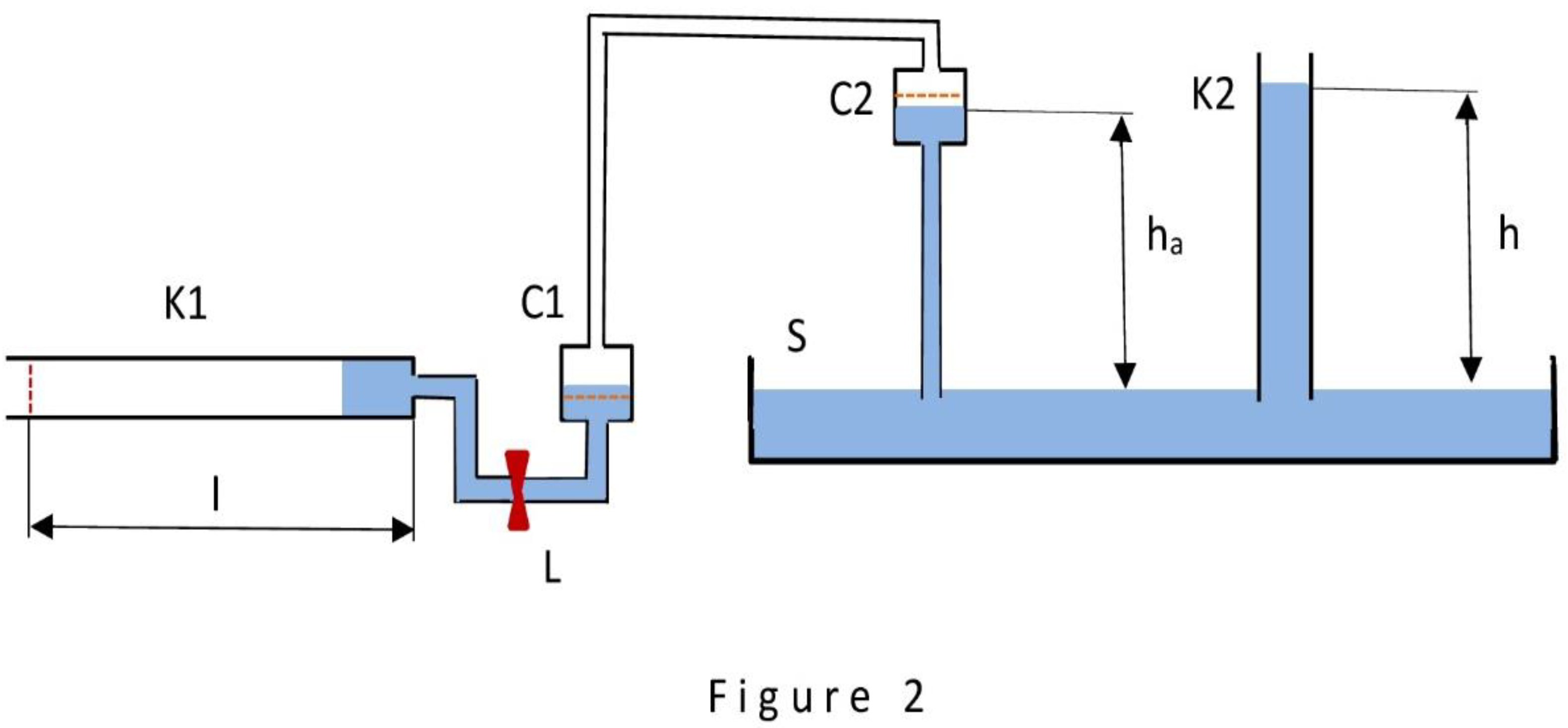
The first variant of the device is shown in Figure 2. This variant is not yet suitable for practical use. This is the purpose that was pursued during its development. This extremely simple version of the two-stream device, already capable of performing the functions of an energy generator, turned out to be convenient for analyzing the process of transpiration in terms of force and energy and allowed to easily find the cause of the energy gain. Also, this version proved convenient for clarifying the formula for calculating the magnitude of this gain. Moreover, during the design process it was found out that the device turns out to be convenient for demonstration of a special property of surface tension force, which makes it different from other forces acting in nature (gravitational forces, electromagnetic forces and others). The property in question is the following: the surface tension force is able to stop and resume its action within a transpiration device in a controlled manner. This unusual property turns such a device into a kind of engine that consumes water as fuel. This is how the above is discovered.
This first variant of the device is similar to the water wheel of transpiration design (WWTD) described in detail in [2], which allows here to describe the features of its operation briefly. The operation of the device is described as follows. The difference from WWTD is that in this case the role of evaporator is performed by capillary K1, located strictly horizontally and exactly at the height corresponding to the water level in cell C1. As a result of water being sucked into capillary K1 (the only active element of the device), a vacuum is created in cells C1 and C2, which forces a portion of water to rise from source S to cell C2 to a height ha. Capillary K2 of the same diameter as capillary K1 is depicted with the only purpose: to show that the height ha cannot exceed the height h of the water column spontaneously appearing in capillary K2. The presence of lock L in the circuit allows to organize a cyclically repeating mode of operation of the device: when the lock is open, capillary K1 is gradually filled with water and the next portion of water is forced to rise from source S to cell C2; when the lock is closed, there is a single action - evaporation of water from the capillary K1 through its open end into the atmosphere. Already a cursory analysis of the operation of the device in Figure 2 draws attention to the fact that surface tension force has the ability to cyclically re-wet the inner surface of capillary K1 an unlimited number of times and perform the work of raising new and new portions of water from the source S into the cell C2. The phenomenon of transpiration suggests how this ability is achieved: after closing the lock L, the water simply evaporates from the capillary K1 into the atmosphere, freeing the wetted surface from water and making it suitable for another re-wetting. This is how the unusual property of the surface tension force is revealed: this force, due to its controlled (by means of the lock L) ability to stop and resume its action, make us look at the device in Figure 2 as a device capable, with a simple technical modification, of turning into a kind of engine that uses the water entering it for evaporation as fuel, as noted in [2].
We will now show that the device in Figure 6 can perform the simplest functions of an energy generator and that in this case the cause of the gain in energy is transparently revealed and a formula is simply derived to calculate the magnitude of this gain. Let us assume that at each step of sucking water inside the capillary K1 the water fills it to the length l. Then, the volume of water portion V entering the capillary K1 is equal to:
V = πr2l,
where r is the inner radius of capillary K1.
During the filling of the capillary K1, exactly the same portion of water V = πr2l rises from the source S into the cell C2 to a height ha, which in the limiting case can be chosen to be equal to the height h calculated in accordance with Jurin's law [3]:
where σ is the surface tension, Θ is the contact angle, ρ is the water density, and g is the acceleration due to gravity. When making a physical model of the device, the height ha was chosen significantly lower than h: in this case, due to the significant superiority of the degree of rarefaction in the cells C1 and C2 over the pressure of the water column from the cell C2 to the source S, the process of filling the capillary K1 (with the open lock L) occurs at a noticeable speed, convenient for observation by the experimenter. Yet, when analyzing the formulas, it is more convenient to proceed from the assumption that the height ha practically coincides with h. In our calculations we will proceed exactly from this assumption - it will simplify the formulas considerably. Given this assumption, when each successive portion of water of volume V is lifted to a height h from source S into cell C2, work A is done, equal to:
h = 2σcosΘ/ρgr,
A = Vρgh
Given that V = πr2l and h = 2σcosΘ/ρgr, we obtain:
A = 2πrlσcosθ
Let us denote by S = 2πrl the area of the inner surface of the capillary K1 of length l wetted with water. Then:
A = Sσcosθ
Formula (2) is utmostly simple and helps to determine the essence of the processes occurring in the device in a transparent way. The cause of work A (and energy gain) is the process of wetting the inner surface of the capillary K1 with the area S. This process is energetically advantageous: when the meniscus moves in capillary K1 and its inner surface becomes wetted, the surface tension force does work. The amount of work, according to formula (2), is unambiguously determined by the size of the wetted surface S. The second factor (σcosΘ) is the tangential component of surface tension, a constant value. In terms of energy, the operation of the device is now described as follows. The portion of energy generated by wetting the capillary K1 is completely (in case ha coincides with h) or partially (in case ha is less than h) spent on the work of lifting the portion of water from the source S into the cell C2. If we organize a periodic withdrawal of the water accumulating in cell C2 at a height ha and directs it, for example, at the blades of specially installed water wheel (the wheel is not shown in Figure 2), the energy generated by the wheel becomes our energy gain. Thus the possibility arises of looking at the device shown in Figure 2 as a source of energy. (The waterwheel concept comes in handy almost always when the need arises to formalize the extraction of energy from a transpiration device by means of a simple technique. In the course of the paper, this technique will be used repeatedly).
From the very beginning of the design of this first variant, it was obvious that the time of water evaporation from the capillary K1 could take an unacceptably long time, counted in days with the capillary length measured in tens of its diameters. Taking this into account, a second variant of the device, free from this disadvantage, was developed in parallel.
The second variant (Figure 3) can already be considered as the simplest energy generator. This variant differs from the first one by using as an evaporator, instead of a single capillary K1, a flat assembly (evaporator E) of many maximally shortened capillaries; the plane of this assembly coincides with the water level in the cell C1. It is assumed that the working length of each of the capillaries of the evaporator E does not exceed one to two capillary diameters. It is also assumed that the time of water evaporation from all capillaries of the evaporator E through their open ends, in this case, corresponds to the tabulated values of water evaporation from free surfaces determined according to [4].
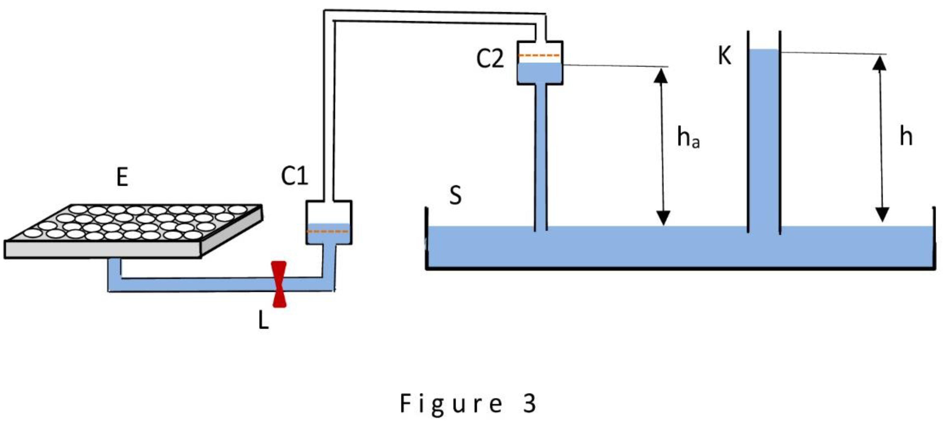
In order to visually observe the operation of both versions of the device, two physical models were made that met two simple requirements. First, they should provide maximum visibility of water movement along two routes: the route formed by capillary K1 (evaporator E in the second model) and cell C1 and the route formed by source S and cell C2. Secondly, they should allow us to evaluate on a qualitative level the rate of water evaporation from capillary K1 (first variant) and from evaporator E (second variant), when lock L is closed.
To meet these requirements, a glass tube with an inner diameter of 1.2 millimeters and a length of 40 millimeters was used as capillary K1 in the first model. Such a tube holds up to 40 cubic millimeters of water, and the movement of such an appreciable volume of water is readily detectable when observed by the experimenter in both streams (routes). In the second model, the flat assembly of evaporator E was formed by 40 glass tubes 1.2 millimeters in diameter and 2 millimeters in length. The number 40 was chosen so that the volume of water entering them for evaporation could still reach 40 cubic millimeters. In order to ensure a convenient for observation speed of water movement, the height ha of the rise of a portion of water from the source S into the cell C2 was chosen to be 10 millimeters, i.e. significantly lower than the height h, which is about 22 millimeters, calculated for a glass capillary with an inner diameter of 1.2 millimeters according to Jurin's law (1). Due to this ratio of ha and h, the movement of water from cell C1 into capillary K1 in the first model and into evaporator E in the second model, as well as from source S into cell C2 in both cases, occurred at a speed noticeable to the observer's eye. Transparent cylinders with an inner diameter of 8 millimeters were used as cells C1 and C2 and source S.
The demonstration experiments performed with both physical models were from the very beginning aimed at evaluating only the qualitative side of the observed processes and, in general, confirmed the performance of both variants of the first device at the qualitative level. The time of evaporation of 40 cubic millimeters of water into the atmosphere from capillary K1, in the first case, was more than 120 hours; in the second case, the time of evaporation of the same volume of water from evaporator E was within one hour, which corresponds to the tabulated values for evaporation from open surfaces in laboratory conditions, determined in accordance with [4].
Three Ways to Generate Energy Using the Subtle Properties of Water and Three Models of Energy Generator
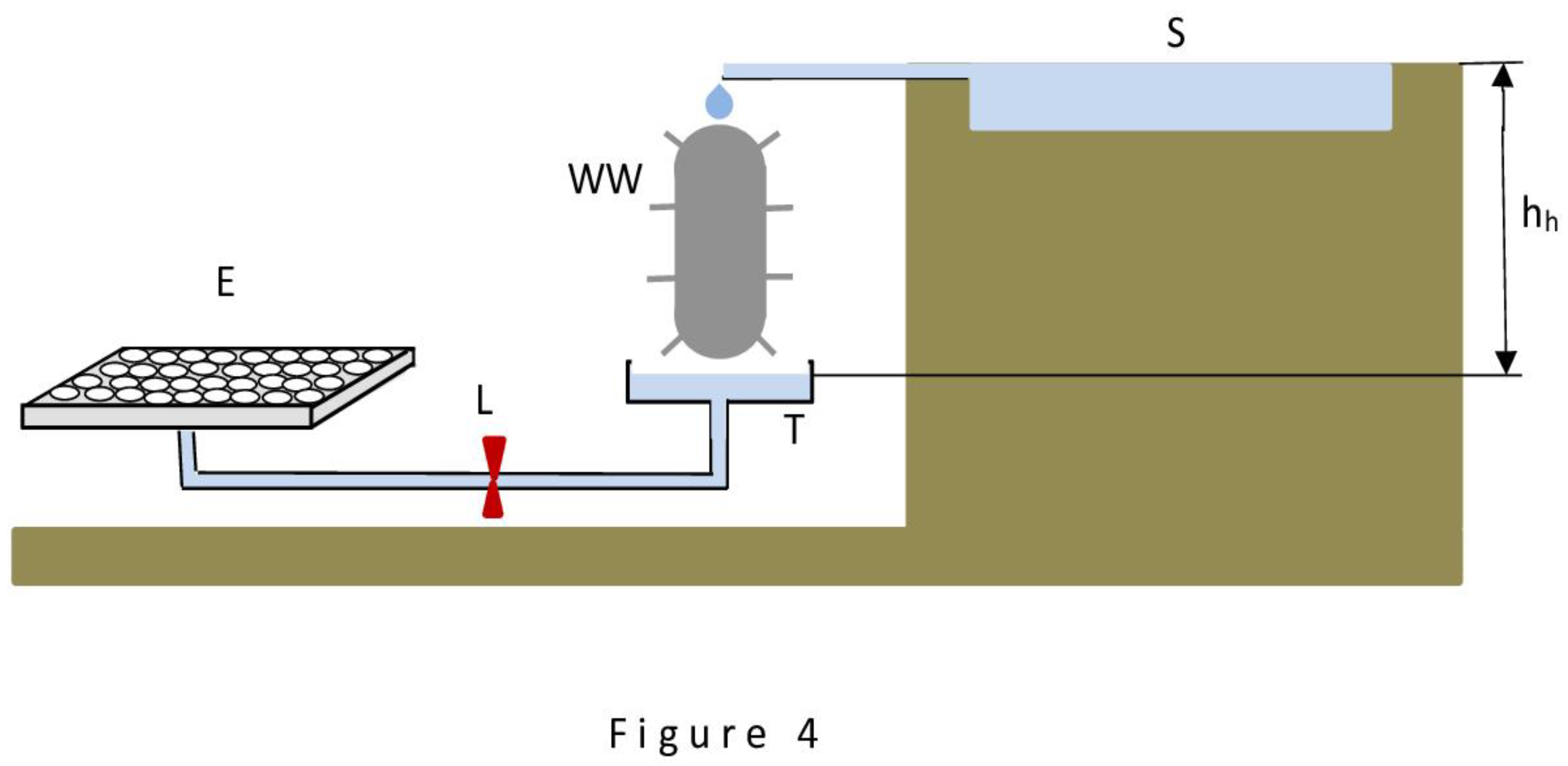
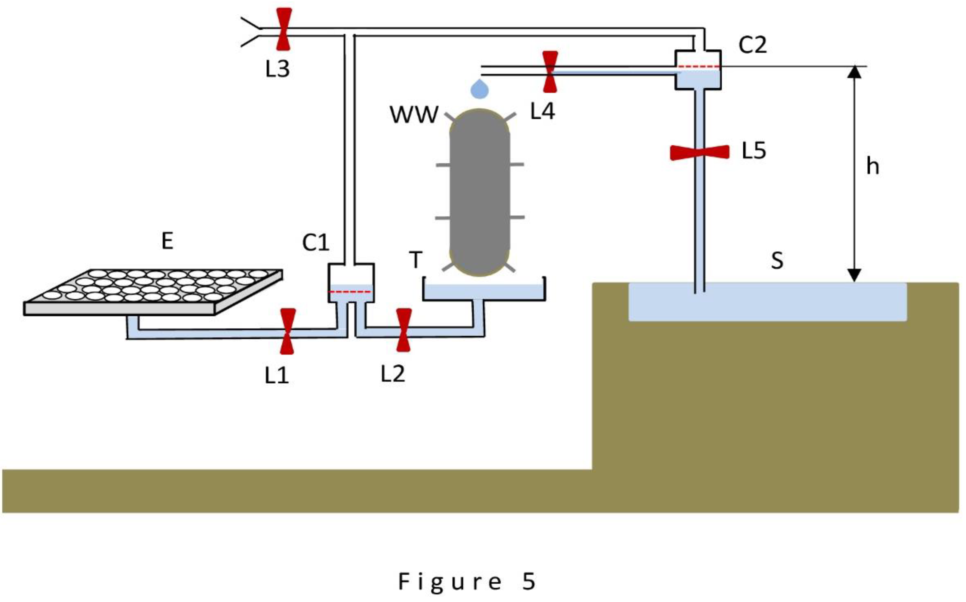
This part is made in the form of presenting the results of the design of three models of devices (hereinafter, as before, simply devices) capable of implementing the three selected ways of energy generation. Schematically, these devices are presented in Figure 4, Figure 5 and Figure 6 using a familiar set of basic elements: evaporator E, cells C1 and C2, source S, trough T and switching locks, to which is added a water wheel WW - with its help is realized the selection of the won energy. Figure 4 shows a device that uses the gravitational property of water and the property to evaporate; Figure 5 shows a device that uses two subtle properties of water; Figure 6 shows a device that uses all three properties of water. The drawings are performed in a style that emphasizes the following attractive fact: the devices depicted in Figure 4 and Figure 5 appear to be special cases of the device depicted in Figure 6. (It is easy to make sure of it: it is enough to mentally transform Figure 6 by alternately zeroing first h and then hh, and we will get first the analog of Figure 4 and then the analog of Figure 5). This fact allows us to limit ourselves to analyzing the operation of only the device in Figure 6 as a general case.
The operation of the device in Figure 6 is described in the following terms. It is assumed that at the initial moment all locks are closed and all vessels (cells C1 and C2, source S and trough T) are filled, as shown in the Figure 6, and evaporator E is free of water. Also, to simplify the reasoning, it is assumed that all actions to monitor changes in the water level in the vessels and to control the locks in a correct way are performed by the operator. The operation of the device is carried out in two stages.
The first stage begins after opening the locks L1 and L5 (the rest remain closed). Then begins a relatively rapid process of sucking water into the evaporator E, generating rarefaction in cells C1 and C2 and raising water from the source S to the cell C2, as described in the case of the devices in Figure 1 and Figure 2. When the water level in cells C1 and C2 reaches the dotted lines, the first stage ends and the second stage begins. Locks L1 and L5 are closed and locks L2, L3, L4 are opened, thus restoring the previous water level in both cells C1 and C2 and supplying a portion of water from cell C2 to the blades of the water wheel WW. (The source S is assumed to be inexhaustible, and the capacity of the trough T is assumed to be much larger than the capacity of cell C1, so that the outflow of a portion of water from the trough into cell C1 does not lead to a noticeable change in the water level in the trough). After water level is restored, all locks are closed, but the second stage does not end: the slow process of evaporation of water available in evaporator E continues. How short is the process of water level restoration in the vessels and how long is the process of water evaporation in the second stage is determined by the operator; the duration of both processes depends on the general characteristics of the device. Replacing each other, both stages can be repeated indefinitely.
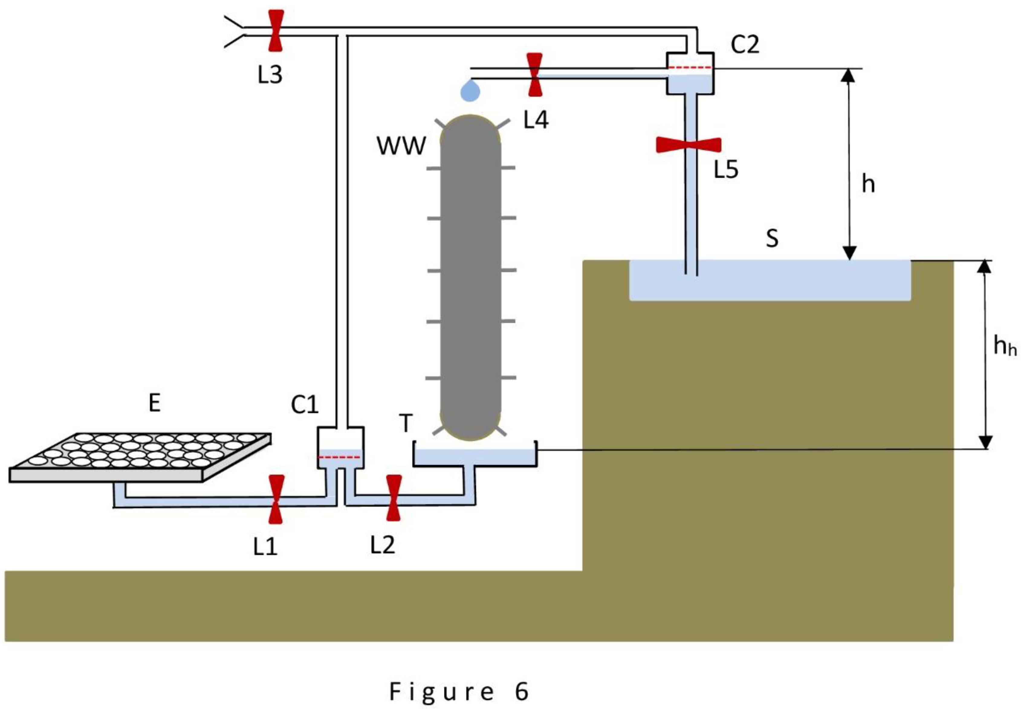
The subject of main interest in the analysis is the performance of the device in Figure 6, i.e. its power as an energy generator. Let us perform the power calculation.
The power of the device in Figure 6 is most correctly calculated using the formula (1) obtained in the first part. In this case, the power is completely determined by the characteristics of the evaporator E: it is only necessary to calculate the total internal surface area of the capillaries or pores forming the evaporator and subject to regular wetting, and multiply it by the surface tension force (σcosΘ), and then divide by the time spent on wetting. However, this way turns out to be complicated (calculating the total area of capillaries is too difficult, especially in the case of porous evaporator material) and not transparent. The way of taking into account the secondary parameters characterizing the device operation is much simpler. These parameters are: the volume of water evaporating from the evaporator surface per unit time and the height of rise of exactly the same volume of water from the source S to the cell C2. Simple multiplication of the two parameters gives the power of the device. The volume of evaporating water in our case is determined by multiplying the value of the evaporator surface area by the evaporation rate from open surfaces, determined by generally recognized tables depending on the ambient conditions [4]. Taking this path, let us determine in what range the capacity of the device in Figure 6 can be.
We take into account the following circumstances. First, the larger the open area of the evaporator E available for water evaporation, the larger the volume of evaporated water. Second, the smaller the internal diameter of capillaries (pores) forming the evaporator, the greater the sucking force of the evaporator, i.e., the greater the height of water rise h from the source S to the cell C2. Third, the amount of energy obtained also depends on the height hh to which the trough T and the evaporator E are lowered. In pursuit of maximum device performance, we should use evaporators with maximum (within reasonable limits) open surface area and with maximum sucking power, and aim to use as large a hh as possible. With respect to the choice of the evaporator with maximum sucking power, there is a natural limitation: the rarefaction in cells C1 and C2 cannot be greater than pure vacuum and, accordingly, the height of water rise h from source S to cell C2 cannot exceed 10 meters. As a result, the pursuit of the maximum sucking force of the evaporator becomes meaningless: when building an evaporator, it is reasonable to choose available materials that provide it with a moderate sucking force of no more than 10 meters of water column in absolute measurement. As a result, the range of our choice of parameters is narrowed: we must choose a height h not exceeding 10 meters, but we are still free to choose the height hh and the size of the evaporator.
For simplicity, let us choose a device with heights h and hh both equal to 10 meters, and determine the range of available power in this case, changing only the parameters of the evaporator E. (Further within this part the height hh is assumed to be always equal to 10 meters. Moreover, it should be recognized that the value of hh can be significantly higher than 10 meters only in exceptional cases, for example, when the device is used in mountainous terrain; the option of increasing the height of hh by digging extensive pits is not attractive). Here are two examples of power calculations: for a low-power device and for a high-power device.
A suitable analog of a low-power device can be an average tree on the planet, which, according to [5], is capable of raising 200 kilograms of soil water to a height of 20 meters during 15 hours of daylight (or about 13 kilograms of water per hour to a height of 20 meters), i.e., to develop a power of about 0.7 watts. It is not difficult to calculate that our device will exhibit the same power of 0.7 watts in the case when evaporator E can evaporate the same 13 kilograms of water per hour into the atmosphere, causing the same amount of water to rise into cell C2 at a height of 20 meters (the sum of h and hh), to be fed to the blades of water wheel WW. To evaporate 13 kilograms of water per hour, evaporator E must have an area equal to at least 13/0.3 = 43 square meters (a moderate tabulated evaporation rate of 0.3 kilograms of water per hour per square meter of surface area is chosen for this calculation). In this calculation, it is assumed that the entire area of the evaporator is suitable for evaporation; this assumption does not, in our case, lead to gross errors. In general, the evaporator turns out to be a flat structure of small thickness, measured in millimeters, having a relatively large area, measured in 43 square meters. For example, it could be a thin panel a few millimeters thick and measuring about 6 x 7 meters.
To perform the second calculation of the high-power device (the calculation will be refined at the end of this part), we will be guided by the following volume of water consumption (for evaporation) not exceeding the limits of the phenomena observed in nature. As a reference we will take a natural lake of medium size with a surface area of ten square kilometers (ten million square meters), capable of acting as an inexhaustible source of water for our device and located in a terrain, the relief of which allows us to lower the evaporator E to 10 meters below the lake level. Under natural conditions, according to the tables proposed in [4], such a lake evaporates in summer, on average, at least 3000 tons of water per hour around the clock (the same moderate table evaporation rate equal to 0.3 kilograms of water per hour from one square meter of surface is used in the calculation). We will assume that consumption of additional 300 tons of water per hour from the lake for operation of our device (eventually, for evaporation into the atmosphere) will not lead to violation of the natural water balance. This assumption allows us to determine the power that our device can develop. The power is calculated using a simple formula:
where g is the acceleration due to gravity, ρV is the mass of evaporated water, h + hh is the height from which water is supplied to the water wheel WW, t is the time during which this process is performed. In our case, g = 9.8 m/s2, ρV = 300,000 kilograms, h + hh = 20 meters, t = 3600 seconds. Substituting these values into (3), we obtain that in the described case the device is capable of developing a power W of at least 16 kilowatts (round the clock). In this case, it is easy to determine that the evaporator area E must be equal to one square kilometer (one million square meters). The evaporator E, in the simplest variant, can be made in the form of a flat plate a few millimeters thick and a kilometer by kilometer in size.
W = gρV(h + hh) / t
This gives a first rough estimate of the range of power that the new type of generator is most likely to have: from a fraction of a watt to about 16 kilowatts. If in the minimum case our generator is equivalent to one average tree, then in the case of 16 kilowatts it becomes equivalent to an average-sized forest of more than 20,000 mature trees in an area of, for example, 100 hectares.
The above two power calculations are easily transferred to the case of the devices in Figure 4 and Figure 5 as special cases of the device in Figure 6. The capacity of the devices in each of these two cases is smaller: at the same evaporator performance, the height h + hh from which water is supplied to the water wheel WW blades is reduced (one of h and hh is zero).
The final estimation of the upper power limit of the proposed devices can be done only in conditional sentences. The reason is that in particular cases of mountainous terrain, allowing to lower the evaporator to the height measured in hundreds of meters, and existence of inexhaustible sources of fresh water, allowing evaporation of unlimited volumes of water, the power of hydro stations can reach indefinitely large values; however, these cases cannot be a reference point for a sober assessment. It is most logical to be guided by an estimate of a few tens of kilowatts - such a figure both reflects the modest estimate of 16 kilowatts obtained for the general case of relatively affordable hydro station and, at the same time, takes into account the possibility of the presence, in each individual case, of particularly favorable external conditions.
It is important to note that, in the case of these three devices (Figure 4, Figure 5 and Figure 6), it is not necessary to build and test physical models: the performance of these two-stream devices is confirmed by the performance of the waterwheel WWTD underlying them. The report on testing of the physical model of WWTD is given in [2].
Discussion and conclusions: on the prospects of creating new type of hydro power stations
At the beginning of the paper, an estimate of the amount of energy produced by the planet's plants in the process of transpiration is given: this amount is comparable to the amount of energy produced by all hydro stations built by man. The path that nature took using the phenomenon of transpiration can be easily traced using the example of trees. Multitude of microscopic structures that perform the function of evaporator are united within a single leaf of a tree. In turn, set of leaves are combined to form a tree crown, set of trees are combined to form a forest, and set of forests are combined to form a planet-scale forest. The above allows us to point out the advantage that artificial transpiration devices have: in this case, a single artificial device is able to fulfill the role of both a single leaf of an imaginary tree, a single tree, and an entire forest of trees, depending on the task assigned to the device. The reason is that the artificial device is free from the limitations dictated by the laws of survival operating in living nature. The evaporative element (analogous to a tree leaf) in this case can reach size measured in square kilometers. The device itself can be similar to the devices in Figure 4, Figure 5 and Figure 6at the designer’s choice.
The calculations made in the second part show the price to be paid for the possibility of obtaining clean energy by means of artificial transpiration devices. This price translates into an impressively large size of the evaporator and an impressively large volume of water evaporated into the atmosphere. At the same time, it can be shown that the forested areas of the planet show no less intensity of water circulation. This can be verified in the following way. We will do it in terms of energy. According to [1], the natural transpiration process provides, on average, 0.03 watts of energy to raise water into the crowns of trees, in terms of one square meter of territory occupied by the forest. Let's calculate what energy is obtained in our case, in terms of one square meter of evaporator area (in our case, water moves from top to bottom, giving energy to the water wheel). The second part shows an example of the device in Figure 6, with 16 kilowatts of power when using a one million square meter evaporator; on a per square meter area basis, this is 0.016 watts per square meter, which is about the same as the above estimate. The discrepancy between the numbers 0.03 and 0.016 can be explained by the following reasons: the rate of water evaporation in forest conditions can be higher on average than the moderate rate accepted in our calculations, equal to 0.3 kilograms of water from one square meter per hour; in addition, the productivity of tree crowns at water evaporation appears to be higher than that of a simple flat evaporator, due to the complex structure of crowns and the high value of leaf index [6] - a coefficient characterizing the evaporative efficiency of crowns. The check can be repeated in terms of evaporator area or volume of evaporated water - the result will be similar.
Now the first conclusion can be drawn: that the evaporator size and evaporated water volume obtained in the calculations correspond to the natural scales demonstrated in the plant world and which should be assessed as optimal.
Taking into account this first conclusion, we can formulate the main conclusion summarizing the work performed: the models of devices presented in Figure 4, Figure 5 and Figure 6can be considered as the first basic models of energy generators, using the subtle properties of water and having significant power. The performance of the models has been verified by physical modeling and is confirmed in the world of plants using the phenomenon of transpiration. The development of models to the level of functioning energy generators can be realized, in general, according to the scheme demonstrated in the world of plants: each leaf of a plant (tree) acts as an autonomous energy generator of limited power, but the whole mass of leaves is united in a powerful network that supplies energy to the whole plant. In practice, this scheme can be realized as follows. Each newly created energy generator remains fully an autonomous hydro station and can take use of all the local advantages provided by the environment (such as the presence of a water source enclosed by dikes and dams, or existing on an elevated site, allowing the evaporator to be placed well below the water level and significantly gain in power). At the same time, each hydro station can be incorporated into the overall power network. According to the obtained estimates, the capacity of autonomous generators can reach at least tens of kilowatts, the total capacity of the network can reach values comparable to the capacity of the network formed by conventional type hydro power stations.
Justification of the feasibility of developing new type generators can be made briefly in the following expressions.
First of all, it should be emphasized that all devices of this type are extremely simple. The devices require mostly widely available materials (capillaries, porous materials and the like) that do not require complicated processing and easily allow automation. Large size of evaporator do not mean a significant increase in the complexity of the devices, increasing only their cost in a simple, arithmetic progression.
An important advantage of the new generators is that they are able to generate energy around the clock and stable in almost any geographical conditions, including the complete absence of sunlight, with only two requirements for operating conditions: positive ambient temperature and humidity below 100%.
Also, generators of this type are friendly to the environment and do not produce harmful emissions. The factor of evaporation of significant volume of water into the atmosphere by the generator has rather positive significance: in the current situation of intensive deforestation, the share of evapotranspiration on the planet scale is steadily decreasing, and the use of this type of generators can only partially compensate for this reduction [7,8].
References
- Quetin, G. , Anderegg L., Konings A., Trugman A. Quatifying the global power needed for sap ascent in plants (2022) Journal of Geophysical Research: Biogeosciences 127 (8). [CrossRef]
- Yakovenko Y. The Ability of Artificial Transpiration Devices to Raise Water to Any Given Height and the Prospects of Creating Large Artificial Transpiration Systems as Sources of Clean Energy 2024. [CrossRef]
- Pierre-Gilles de Gennes, Françoise Brochard-Wyart, David Quéré Capillarity and Wetting Phenomena - Drops, Bubbles, Pearls, Waves (2002) Alex Reisinger Springer ISBN 978-0-387-00592-8.
- Wilfried Brutsaert Evaporation into the Atmosphere. Theory, History, and Applications Dordrecht: Springer, 1982., 302 с., ISBN 978-90-481-8365-4.
- Wullschleger, S. , Meinzer F., Vertessy R. A review of whole-plant water use studies in tree Tree Physiol. 1998 Aug – Sept; 18 (8_9): 499 – 512. [CrossRef]
- Breda, N Ground-based measurements of leaf area index: A review of methods, instruments and current controversies Journal of Experimental Botany (2003) 54 (392): 2403–2417. [CrossRef]
- Hannah Ritchie (2021) Deforestation and Forest Loss https://ourworldindata.org/deforestation [Online Resource].
- Pendrill F., Persson M., Godar J., Kastner T. (2019) Deforestation displaced: Trade in forest-risk commodities and the prospects for a global forest transition Environmental Research Letters. [CrossRef]
Disclaimer/Publisher’s Note: The statements, opinions and data contained in all publications are solely those of the individual author(s) and contributor(s) and not of MDPI and/or the editor(s). MDPI and/or the editor(s) disclaim responsibility for any injury to people or property resulting from any ideas, methods, instructions or products referred to in the content. |
© 2024 by the authors. Licensee MDPI, Basel, Switzerland. This article is an open access article distributed under the terms and conditions of the Creative Commons Attribution (CC BY) license (http://creativecommons.org/licenses/by/4.0/).
Copyright: This open access article is published under a Creative Commons CC BY 4.0 license, which permit the free download, distribution, and reuse, provided that the author and preprint are cited in any reuse.


