Submitted:
09 December 2024
Posted:
10 December 2024
You are already at the latest version
Abstract
This paper presents enhancing voltage and power stability in distribution system with photovoltaic from benefits of battery energy storage. This objective which is use photovoltaic distributed generation and battery energy storage system in order to reduce electric power loss to minimum loss and generate voltage up to or above 0.95 p.u which is thailand voltage standard. This paper has experiment in MATLAB test in the system for the case study is a IEEE 33 bus distribution system. There are 5 study case in this paper. Case 1 is before installation photovoltaic and battery energy storage system. Case 2 is installation photovoltaic distributed generator in 4 buses. Case 3 is installation photovoltaic distributed generator in only one bus. Case 4 is installation photovoltaic distributed generator in 2 buses that have most voltage drop. Case 5 is installation photovoltaic distributed generator in 4 buses and battery energy storage system in 2 buses. The result show case 5 is the best because none numbers of voltage drop is below 0.95 per unit and the lowest power loss.
Keywords:
distribution system
; battery energy storage system
; photovoltaic system
; voltage drop
1. Introduction
Supply voltage in far away at the end of power line both end have power lost from voltage fluctuation because internal load line resistance on electric supply voltage fluctuation or electric power does not require as standard. One of solutions is set auxiliary generator up which it is a small technology for electric supplier supplies. Dis-tributed generator that is a solution use with small technology for electric generation that requires to electric supplier’s electric system. At the present, it implements renewable technology in Distributed generator [1].
In 2012 [2], this photovoltaic use in a tiny lithium-ion battery charger which has high efficiency but this charger uses in low power in application type. In 2014 [3], renewable energy type which is good to generate electric in an isolated area such as wind and solar ray, when both renewable electric generator type connect to the grid system it is able to cut electric energy cost from electric supplier. In 2017 [4], photo-voltaic which is not only cuts cost from electric supplier but also reduce carbon dioxide emission from conventional electric generator. In 2020 [5], there was studied improvement voltage sag with photovoltaic on distribution system. Tested in 69 bus distribution system. In 2023 [6], there was study about selective sizing battery energy storage system with photovoltaic system which is installed in urban area on Maltese islands. Due to limited installed area in this islands, battery have to be calculated in optimal size before it is installed in the system.
This paper presents to apply photovoltaic and battery energy storage system voltage drop in electric supply system improvement and increase efficiency in distribution system. This distribution system tested in IEEE 33 bus distribution system with a program MATLAB and analyzed in 5 cases. Photovoltaic system as shown in Figure 1.
2. Photovoltaic
Photovoltaic is an invention which is able to convert solar energy become to direct current electric. This Effect is called Photovoltaic laboratory. In year 1954 Photovoltaic was finally invented and used in the first place on the world in USA that has efficiency at 6 percent. Nowadays photovoltaic has been developed become more efficiency value. Photovoltaic has objective in early is to generate electric from solar ray in space project. After space project, it is use in generally and expand to photovoltaic world industry grade.
One of the most important material in photovoltaic production monocrystalline semiconductor type is called silicon. Nowadays silicon is popular to use in photovoltaic production in order to silicon which is the second most available in the world crust is able to supply and produce easily so the cost to produce is low and produce fast. It is a durable material which has a long lifespan. Furthermore silicon has additional properties such as heat property, light property, mechanical property, natural property and electronic property. Photovoltaic made of silicon in one which has high purity. In monocrystalline photovoltaic production, first smelt silicon in induction smelter at temperature 1,500 celsius. In order to product in gigantic silicon which has separate in 2 types one is p-type silicon which infuses the boron in production and the other one is n-type silicon which infuses the phosphorus in production. Then let production giant crystalline cooldown which has a giant cross section pulls those rod out of smelter and cut this rod to a thin plate. After this process these silicon plates infuse between interface in both two types, photovoltaic n-type silicon and p-type silicon on these plates by diffusion technique at temperature 1,000 celsius. After that on front site of solar ray in photovoltaic is cathode and back site of solar ray in photovoltaic is anode. Both of these photovoltaic have installed thin film layer on their surface to make solar ray reflect as less as possible. At last assemble in photovoltaic by glass to protect photovoltaic and use silicon, Ethylene vinyl which is plastic pellet has flexible property easy to prevent moisture [7]. Layer photovoltaic as shown in Figure 2.
In first layer which is called front electrode works as electron receiver n-type silicon. This layer has metal property commonly made of silver. In second layer is called n-type silicon which is photovoltaic n-type silicon infuses with phosphorus in this layer. Due to phosphorus which has one valence electron more than silicon, this valence electron which does not have electron to bind receives the little amount of energy that is able to conduct electric. So cathode has been built on photovoltaic cell base. After that photovoltaic infuses with boron on the top of layer photovoltaic cell. Due to boron which has one valence electron less than silicon, boron which lacks valence electron has a space for electron or hole. Anode has been built on the top of photovoltaic cell. Due to electron in photovoltaic cell flow from the base to the top which generate negative cathode so it is called n-type. In the third layer is called p-n junction layer which let p-type silicon and n-type silicon installs on layer both layer there is a junction between them which is called p-n junctions. Photovoltaic p-type silicon generates positive electrode and n-type silicon generates negative electrode and generates voltages at p-n junctions here. In the fourth layer is called p-type silicon. This silicon type infuses with boron during production. During boron infusion which has one less electron than silicon needs valance electron. Then it makes a hole to receive an electron or hole in silicon. After that infuses phosphorus on the top of Photovoltaic cell. Due to phosphorus has one more electron than silicon. Valance electron on phosphorus needs to be bonded, when Valance electron receive the little amount of energy, it releases itself so it is able to conduct electric so cathode has been built on the top of photovoltaic cell and electron in this photovoltaic cell flow from the top to the base. Due to photovoltaic cell type generate Anode so it is call photovoltaic cell p-type. In the fifth layer is called back electrode which is under the p-type silicon has a metal plate. It is works as hole collector that is on photovoltaic cell [8].
3. Power Flow Equation
Real power and reactive power between buses calculate by equation (1)-(2) [9].
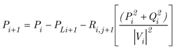
Power loss in line connection between bus I and bus i+1 calculates by equation (3).

| Where |  |
is real power and reactive power value at bus i |
 |
is voltage value at bus i | |
 |
is line resistance value between bus i and i+1 | |
 |
is line reactance value between bus i and i+1 |
4. Inverter
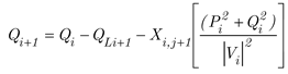
Due to electric alternative current which is able to supply power in a faraway path becomes a standard electrical engineering. Further electric consumer device or load design commonly for electric alternative current. However photovoltaic which is an invention converts solar ray energy becomes electric energy direct current form. This electric direct current needs inverter to invert direct current to alternative current in order to let electric consumer device or load in the system is able to consume electric that is generated by photovoltaic cell. The photovoltaic cell has works as follow. It converts solar energy becomes electric energy in direct current. After that supplies to store in battery storage and supplies to inverter which inverts electric direct current to alternative current in order to electric consumer device or load [10]. Inverter system on factory as shown in Figure 3.
In the past inverter inverts direct current to alternative current that has an unreliable efficiency or less efficiency when use in the photovoltaic system. Inverter was invented due to the lost electric energy overall is so much make system much worse. Due to less efficiency in particular electric consumer consumes more electric power. Nowadays there is an inverter development which make a better efficiency as the perfect tool in inversion invert to electric energy from direct current to alternative current. So inverter which is in characteristic term must have high efficiency. Inverters invert commonly input energy electric direct current in 90 percent or more become output in alternative current. However inverters perhaps has a top efficiency only at a time where it works nearby output. Inverter use commonly in load that require voltage from inverter. So to choose inverter should has more voltage than voltage require on the load which inverter must maintain output in 50 hertz. Therefore under some condition and harmonic distortion inverter must cut unnecessary output in order to reduce heat in electric consumer device [11].
Inverter in photovoltaic system which has basic objective that is to invert electric direct current from both photovoltaic and battery storage becomes to alternative current and supplies to load. Further it is able to supply back to power grid. Structure inside inverter are consists of first converter circuit which is a circuit convert signal in photovoltaic system converts electric alternative current to direct current. Second inverter circuit which is an important circuit for electric energy from photovoltaic system. In order to supply the electric to electric consumer device load in electric system, inverter works in photovoltaic system the same as transformer in power electric system. It receives electric energy from photovoltaic which converts solar ray energy to electric direct current and inverts to alternative current. After that it supplies the electric that inverts from photovoltaic to electric consumer or load on the electric system in house or building. This electric is able to work without electric from electric supplier. Third control circuit controls converter circuit and inverter circuit [12].
5. Batteryless Grid Tiled Inverter System
Batteryless grid tiled inverter system is an electric which connect between photovoltaic and power line from electric supplier. The batteryless grid tiled inverter form consists of photovoltaic, inverter and power line those 3 connect together electric is generated by photovoltaic with power line directly. Electric current which is generated by photovoltaic is able to flow in and out to power line when this system generates electric more than system requires. Batteryless grid tiled inverter system shown in Figure 4.
This inverter type uses for electric system load connection. In order to use electric which is generated from photovoltaic supplies to electric consumer device or load must work with electric that receives from electric supplier every time. Because electric which is generated from batteryless grid tiled inverter does not have stability which is depend on how much electric is generated by photovoltaic. So this electric must supply only when there is an electric current from electric supplier as addition in order to make stability supply or in other case this inverter must use in this mode. In order to sell electric which is generated by photovoltaic back to electric supplier. Besides when it is black out case or voltage drop, inverter must cut electric. in order to do not supply electric out to power line to electric supplier automatically. In order to do not let electric current out and electrocute to electric supplier’s worker during maintenance [13].
Batteryless grid tiled consumes electric from photovoltaic only day time or sunny day which this system builds for electric generation during day or sunshine day which is able to compatible with electric from electric supplier. During Photovoltaic is able to generate electric current more than the system need. This system use electric current from electric supplier less so it is able to cut electric cost. During there is no sun ray or night time. This system switches to use electric from electric supplier normally. This inverter works in grid tiled mode which is photovoltaic converts solar energy becomes as electric energy direct current. After that electric energy supplies to electric consumer device that inverts from direct current to alternative current which is inverters. It supplies electric alternative current to in house factory or even load in electric system. This inverter installs parallel with electric supplier’s electric system. Electric system in house or factory consumes electric current from Photovoltaic and electric current from electric supplier together. The benefits in battery less grid tiled inverter system are cut the cost to spend to electric that means generate electric and consume in house to cut cost and supplies back to power line. However, there is a constraint in Battery less Grid Tiled Inverter system [14].
Battery less grid tiled inverter has a maximum voltage tracker system, has ground fault prevention, cut off ac/dc connector or electric current protection equipment, and cut external power line off to uninstall the inverter in safety during maintenance and drains the air from air blockade. Battery less grid tiled inverter is commonly design to install outside and has drain air from air blockade. Battery less grid tiled inverter’s size must require met the load, funds and area constraint [15].
Which is it is able to generate electric only on day or sunshine day. Further electric supplier must supplies electric current as additional too. If electric from electric power line supplier has either black out or voltage drop. Inverter cuts electric off as a safety mode even though there is a sun ray that is able to generate electric.
6. Stand Alone Inverter
Stand alone inverter which is a complete photovoltaic in itself or independent electric from electric supplier or any electric source. So this electric generates from solar ray is collected in battery for photovoltaic which is not compatible with electric system from electric supplier [16]. Stand alone inverter as shown in Figure 5.
This inverter type uses for electric direct current become as alternative current to consume in electric device only. Photovoltaic converts solar ray to electric direct current. Then this electric stores in battery storage which before passes to inverter must have solar Charge controller device separately. This devices controls charging battery that separate each inverter type. Then this electric which supplies to inverter inverts to alternative current. Further this electric consumes in device or load in electric system. This stand alone inverter does not connect with power line or electric grid so it is not in electric supplier’s standard but all device in the system must have safety standard. Stand alone inverter has benefits which are photovoltaic electric consumption for energy storage from solar ray energy during day which uses electric energy in two ways the one way is to supply power electric to device on day and the other way is to store the rest in battery storage from photovoltaic. The rest of electric in battery supplies to electric devices and load in the system at the night. Stand alone inverter has properties should utilization many benefits in continuity voltage input from generator, charging battery, electric surge from over demanding load, and electric surge over capacity charge inverter should supply in high electricity current at prior. In order to start motor or works in many loads start and warns every user or cut electric off automatically when battery power is low. This inverter prevents over supply currents from load in alternative current too [17].
The most important is this generator must generate electric enough as electric device need all the time and must also has electric enough able to operate device during night time too. To every consumer must know before installation this stand alone inverter system is first electric power on every device need to consume electric, second time how long to let consume electric devices consume each as (all day and night) and third estimate overall electric energy of devices when they operate all day and night. To know Photovoltaic and stand alone Inverter are first the Photovoltaic, second controller device controls the charging of battery, third battery storage for photovoltaic, fourth inverter and fifth electric generator. Stand alone inverter has properties should be useful with many benefits in voltage load limit input generator, charging battery and electric surge load [18].
7. Grid Tiled with Battery Back Up Inverter System
Grid tiled with battery backup inverter system which is a system that take both advantages from all 2 types is first it is able to connect with in house or receives electric from electric supplier like battery less grid tiled inverter system and consume electric from battery storage which is store electric from photovoltaic supplies to the same consumer device like stand alone inverter system [19]. Grid tiled with battery backup inverter system as shown in .
Grid tiled with battery backup inverter system work in following. Photovoltaic converts solar ray energy to electric direct current. Then this electric supplies to solar charge controller which charges in battery energy storage system and it supplies to inverter which inverts electric direct current to alternative current has function that is able to optimize how much the current supplies to battery energy storage system or supplies to inverter as priority. Battery energy storage system has been installed to reserved electric energy when there is no solar ray. During daytime or with solar ray, photovoltaic converts solar ray energy to electric direct current. Further it is able to generate more than electric consumer device or load need. This system charges in battery. For Photovoltaic and battery energy storage system, during nighttime or without solar ray, photovoltaic is not able to generate electric, this system supplies electric from battery energy storage system, even electric energy in this system is not enough to supply to load in the grid tiled with battery backup inverter system. The inverter is able to choose electric from electric supplier system to fulfill electric energy as the load in system need [20].
In the case black out from electric supplier, inverter must cut the system off to do not let electric which supplies in house supplies to power line. This electric would be harm to electrician and black out majority in house or factory too. However, if this system separates as reserved, it is able to supply from battery energy storage system or photovoltaic (or both together) inverts to alternative current to supply only device in reserved electric circuit. However, do not let reserved electric supply more than inverter is able to supply. When it has a black out or voltage drop Inverter cuts over electric current off (if it has) to power line for safety. But it is able to charge battery and supply device in house or factory (only circuit separate in reserved electric) normally. Until battery out of power or photovoltaic is not able generate electric by too low solar ray. The grid tiled with battery backup inverter system commonly chooses to charge electric from photovoltaic to battery or supply to electric device prior. To choose device in grid tiled with battery backup inverter system. First the photovoltaic, second the solar charge controller and third battery energy storage system. Beside grid tiled with battery backup, inverter system has additional function such as supply electric from battery to some devices in house during black out even choose photovoltaic to charges battery first or supplies to house in order to cut the cost first [21].
8. Battery Energy Storage System Operation
Photovoltaic system is consists of first photovoltaic converts solar ray energy to electric energy direct current, second inverter inverts electric energy direct current to electric energy alternative current in 1 phase or 3 phases which is depend on inverter type and third is battery energy storage system. Battery energy storage system on factory as shown in Figure 7.
Battery energy storage system is an additional device of photovoltaic which stores an oversupply generated electric more than load needs. Battery energy storage system stores electric energy direct current which reacts chemical as preserved electric energy to supply in the future. Battery energy storage system is a stable supply that relatively on Photovoltaic. When photovoltaic generates electric due to solar ray is low. Besides, battery is able to handle electrical surge when there is a load demand like motor in electric system. Battery most commonly is not efficiency 100% due to some amount of energies lose in heat energy, in chemical reaction during charge and even discharge or over discharge electric that let battery is depleted and does not charge electric back to battery. When acid concentration is too low. The lead plate is corroded. So this system should install battery charge controller as additional in photovoltaic system, in order to reduce damage from discharging from battery [22].
Photovoltaic converts solar ray energy to electric energy direct current. This electric stores in battery energy storage system. When there is no solar ray to convert electric energy or night time and even cloudy weather, due to output from photovoltaic is unreliable to generate electric. Battery which installs in order to store electric energy in photovoltaic system is developed for more storage and more supply electric longer than conventional battery. This is called deep cycle battery which is extra lead thick battery plate has higher resistance inside battery. Thus it is able to charge more electric but it is not able to supply a lot of electric current. This battery is not good in a demanding electric current load. When battery is not supply, the capacity in battery is not lesser capacity than 60 percent and place the battery in cold temperature which is not over than 25 Celsius IF Electric over charge makes battery overheat cause battery degrades faster [23].
9. Power Distribution System
Power distribution system divides in 3 systems one electrical generation system which is system change other energy become as electric energy such as photovoltaic from photovoltaic farm converts solar energy become as electric energy, dam converts potential energy in water become as electric energy, coal electric generator which converts heat energy from burning coal generates electrical generator become as electric energy, When electric energy supplies to transformer to change voltage value to high voltage. In order to reduce loss energy in electric system. After that this high voltage electric supplies to Switchyard. In order to configures electric quality and supplies to transmission system. The transmission system which receives electric from electrical generation system supplies to substation to reduce voltage from high voltage become as medium voltage. The medium voltage supplies in distribution system. This electric supplies to transformer which transforms either higher or lower voltage to consume in house or factory in 1 phase and 3 phases [24]. Power distribution system as shown in Figure 8.
10. Model of Test Distribution System
The application battery storage which is to increase photovoltaic system tests with IEEE 33 bus distribution system as shown in Figure 9.
Table 1.
Line data and load in system IEEE 33 bus during peak load [1].
Table 1.
Line data and load in system IEEE 33 bus during peak load [1].
| No. Branch |
From bus |
To bus |
R (Ω) |
X (Ω) |
No Load Bus |
Load At To Bus | |
|---|---|---|---|---|---|---|---|
| P (kW) | Q (kVAr) | ||||||
| 1 | 1 | 2 | 0.0922 | 0.048 | 1 | 0 | 0 |
| 2 | 2 | 3 | 0.4930 | 0.251 | 2 | 100 | 60 |
| 3 | 3 | 4 | 0.3660 | 0.186 | 3 | 90 | 40 |
| 4 | 4 | 5 | 0.3811 | 0.194 | 4 | 120 | 80 |
| 5 | 5 | 6 | 0.8190 | 0.707 | 5 | 60 | 30 |
| 6 | 6 | 7 | 0.1872 | 0.619 | 6 | 60 | 20 |
| 7 | 7 | 8 | 17.114 | 12.35 | 7 | 200 | 100 |
| 8 | 8 | 9 | 1.0300 | 0.740 | 8 | 200 | 100 |
| 9 | 9 | 10 | 1.0400 | 0.740 | 9 | 60 | 20 |
| 10 | 10 | 11 | 0.1966 | 0.065 | 10 | 60 | 20 |
| 11 | 11 | 12 | 0.3744 | 0.124 | 11 | 45 | 30 |
| 12 | 12 | 13 | 1.4680 | 1.155 | 12 | 60 | 35 |
| 13 | 13 | 14 | 0.5416 | 0.713 | 13 | 60 | 35 |
| 14 | 14 | 15 | 0.5910 | 0.526 | 14 | 120 | 80 |
| 15 | 15 | 16 | 0.7463 | 0.545 | 15 | 60 | 10 |
| 16 | 16 | 17 | 1.2890 | 1.721 | 16 | 60 | 20 |
| 17 | 17 | 18 | 0.7320 | 0.574 | 17 | 60 | 20 |
| 18 | 18 | 19 | 0.1640 | 0.157 | 18 | 90 | 40 |
| 19 | 19 | 20 | 15.042 | 13.55 | 19 | 90 | 40 |
| 20 | 20 | 21 | 0.4095 | 0.478 | 20 | 90 | 40 |
| 21 | 21 | 22 | 0.7089 | 0.937 | 21 | 90 | 40 |
| 22 | 22 | 23 | 0.4512 | 0.308 | 22 | 90 | 40 |
| 23 | 23 | 24 | 0.8980 | 0.709 | 23 | 90 | 50 |
| 24 | 24 | 25 | 0.8960 | 0.701 | 24 | 420 | 200 |
| 25 | 25 | 26 | 0.2030 | 0.103 | 25 | 420 | 200 |
| 26 | 26 | 27 | 0.2842 | 0.145 | 26 | 60 | 25 |
| 27 | 27 | 28 | 1.0590 | 0.934 | 27 | 60 | 25 |
| 28 | 28 | 29 | 0.8042 | 0.701 | 28 | 60 | 20 |
| 29 | 29 | 30 | 0.5075 | 0.259 | 29 | 120 | 70 |
| 30 | 30 | 31 | 0.9744 | 0.963 | 30 | 200 | 600 |
| 31 | 31 | 32 | 0.3105 | 0.362 | 31 | 150 | 70 |
| 32 | 32 | 33 | 0.3410 | 0.530 | 32 | 210 | 100 |
| 33 | 60 | 40 | |||||
11. Flowchart
Flowchart shows procedures to test in this research paper. Flowchart as shown in Figure 10.
12. Case Study
In this study, every bus where it has voltage drop requires either photovoltaic or battery storage size installation. In order to generate voltage up to above 0.95 per unit which is a Thailand standard. There were 5 different condition tests. Due to Metropolitan Electricity Authority every bus that has per unit less than 0.95 which considers as voltage drop on that bus.
Case 1: In this case before installation photovoltaic and battery energy storage system. Case 1 as shown in Figure 11.
Case 2: In this case installation photovoltaic at bus 16, 18, 31 and 33 with size of photovoltaic 180, 240, 240 and 400 kW respectively total size of photovoltaic 1,060 kW. Case 2 as shown in Figure 12.
Case 3: In this case installation photovoltaic at bus 18 with size of photovoltaic 1,060 kW respectively total size of photovoltaic 1,060 kW. Case 3 as shown in Figure 13.
Case 4: In this case installation photovoltaic at bus 18 and 33 with size of photovoltaic 430 and 630 kW respectively total size of photovoltaic 1,060 kW. Case 4 as shown in Figure 14.
Case 5: In this case installation photovoltaic at bus 16, 18, 31 and 33 with size of Photovoltaic 180, 240, 240, 400 kW respectively total size of photovoltaic 1,060 kW and battery energy storage system at bus 14 and 29 with size 40 kWh total size of battery energy storage system 80 kWh. Case 5 as shown in Figure 15.
Table 2.
Location and size of photovoltaic and battery energy storage system.
| Case | Bus Photovoltaic Installation |
Size Photovoltaic (kW) |
Total Size Of Photovoltaic (kW) |
Bus Battery Energy Storage System Installation |
Size Battery Energy Storage System (kWh) |
Total Size Of Battery Energy Storage System (kW) |
|---|---|---|---|---|---|---|
| 1 | - | - | - | - | - | - |
| 2 | 16, 18, 31, 33 | 180, 240, 240, 400 | 1,060 | - | - | - |
| 3 | 18 | 1,060 | 1,060 | - | - | - |
| 4 | 18, 33 | 430, 630 | 1,060 | - | - | - |
| 5 | 16, 18, 31, 33 | 180, 240, 240, 400 | 1,060 | 14, 29 | 40, 40 | 80 |
Table 3.
Result voltage(p.u.).
| No. bus |
Voltage(p.u.) | ||||
|---|---|---|---|---|---|
| Case 1 | Case 2 | Case 3 | Case 4 | Case 5 | |
| 1 | 1.000 | 1.000 | 1.000 | 1.000 | 1.000 |
| 2 | 0.997 | 0.998 | 0.998 | 0.998 | 0.998 |
| 3 | 0.983 | 0.987 | 0.987 | 0.987 | 0.987 |
| 4 | 0.975 | 0.983 | 0.982 | 0.982 | 0.982 |
| 5 | 0.968 | 0.978 | 0.977 | 0.978 | 0.978 |
| 6 | 0.950 | 0.966 | 0.965 | 0.966 | 0.966 |
| 7 | 0.946 | 0.963 | 0.963 | 0.963 | 0.963 |
| 8 | 0.941 | 0.960 | 0.963 | 0.960 | 0.960 |
| 9 | 0.935 | 0.957 | 0.964 | 0.957 | 0.957 |
| 10 | 0.929 | 0.954 | 0.965 | 0.954 | 0.954 |
| 11 | 0.928 | 0.954 | 0.965 | 0.954 | 0.954 |
| 12 | 0.927 | 0.953 | 0.966 | 0.954 | 0.954 |
| 13 | 0.921 | 0.952 | 0.970 | 0.952 | 0.952 |
| 14 | 0.919 | 0.951 | 0.972 | 0.951 | 0.951 |
| 15 | 0.917 | 0.951 | 0.974 | 0.951 | 0.951 |
| 16 | 0.916 | 0.952 | 0.978 | 0.952 | 0.952 |
| 17 | 0.914 | 0.952 | 0.985 | 0.954 | 0.954 |
| 18 | 0.913 | 0.952 | 0.989 | 0.955 | 0.955 |
| 19 | 0.997 | 0.997 | 0.997 | 0.997 | 0.997 |
| 20 | 0.993 | 0.994 | 0.994 | 0.994 | 0.994 |
| 21 | 0.992 | 0.993 | 0.993 | 0.993 | 0.993 |
| 22 | 0.992 | 0.992 | 0.992 | 0.992 | 0.992 |
| 23 | 0.979 | 0.984 | 0.984 | 0.984 | 0.984 |
| 24 | 0.973 | 0.977 | 0.977 | 0.977 | 0.977 |
| 25 | 0.969 | 0.974 | 0.974 | 0.974 | 0.974 |
| 26 | 0.948 | 0.965 | 0.963 | 0.965 | 0.965 |
| 27 | 0.945 | 0.963 | 0.960 | 0.963 | 0.963 |
| 28 | 0.934 | 0.957 | 0.949 | 0.956 | 0.956 |
| 29 | 0.926 | 0.952 | 0.941 | 0.952 | 0.952 |
| 30 | 0.922 | 0.951 | 0.938 | 0.950 | 0.950 |
| 31 | 0.918 | 0.951 | 0.934 | 0.950 | 0.950 |
| 32 | 0.917 | 0.951 | 0.933 | 0.951 | 0.951 |
| 33 | 0.917 | 0.951 | 0.932 | 0.952 | 0.952 |
Table 4.
The results power loss and number bus were has voltage drop.
| Case | Power loss (kW) |
Number bus were has voltage drop |
Total bus has voltage drop |
The lowest voltage drop |
|---|---|---|---|---|
| 1 | 202.45 | 7-18, 26-33 | 20 | 18 |
| 2 | 108.64 | 0 | 0 | 14,15, 30, 31, 32, 33 |
| 3 | 147.17 | 28-33 | 6 | 32 |
| 4 | 110.65 | 0 | 0 | 30,31 |
| 5 | 104.55 | 0 | 0 | 30,31 |
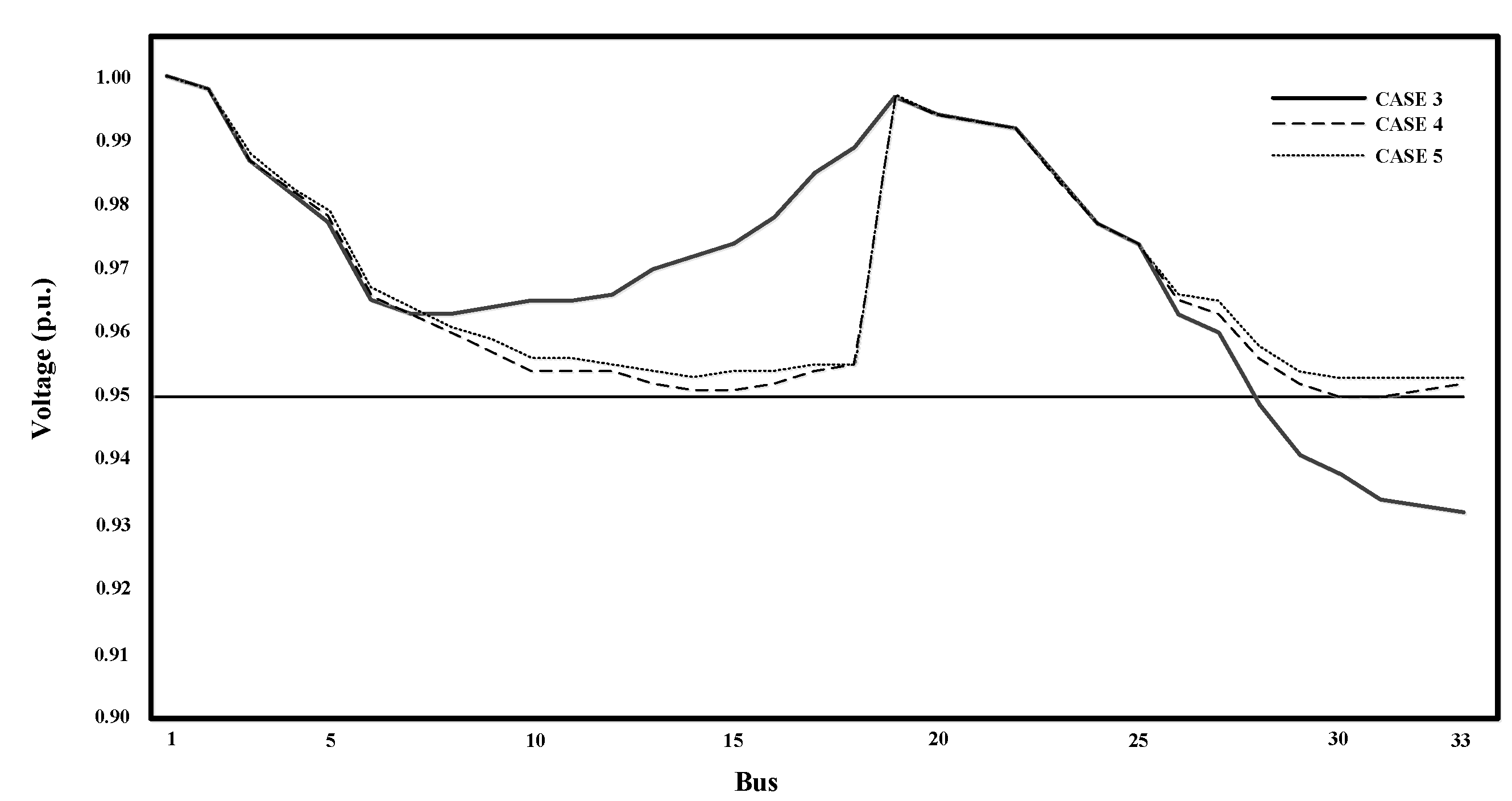
From Figure 16 result adjustment voltage drop case 1 and case 2 this figure is comparison between case 1 it original case no installation photovoltaic and battery energy storage system and case 2 installation photovoltaic distributed generator in 4 bus. Case 1 is before installation photovoltaic and battery energy storage system. Numbers of voltage drop below 0.95 per unit bus are 7, 8, 9, 10, 11, 12, 13, 14, 15, 16, 17, 18, 26, 27, 28, 29, 30, 31, 32 and 33. Total voltage drop buses are 20 buses and the lowest voltage bus is 18. Case 2 installation photovoltaic at bus 16, 18, 31 and 33 with size of photovoltaic 180, 240, 240 and 400 kW respectively total size of photovoltaic 1,060 kW. None numbers of voltage drop is below 0.95 per unit and the lowest voltage bus is 14, 15, 30, 31, 32, 33. From Figure 17 result adjustment voltage drop case 3, case 4 and case 5 this figure is a comparison between cases. case 3 is installation photovoltaic distributed generator in only one bus. case 4 is installation Photovoltaic distributed generator in 2 buses have most voltage drop and case 5 installation Photovoltaic distributed generator in 4 buses battery energy storage system in 2 buses. Case 3 installation photovoltaic at bus 18 with size of photovoltaic 1,060 kW respectively, total size of photovoltaic 1,060 kW. Numbers of voltage drop below 0.95 per unit bus are 28, 29, 30, 31, 32, and 33. Total voltage drop buses are 6 buses and the lowest voltage bus is 33. Case 4 is installation photovoltaic at bus 18 and 33 with size of photovoltaic 430 and 630 kW respectively, total size of photovoltaic 1,060 kW. None numbers of voltage drop is below 0.95 per unit and the lowest voltage bus is 30 and 31. Case 5 is installation photovoltaic at bus 16, 18, 31 and 33 with size of Photovoltaic 140, 240, 200, 400 kW respectively, total size of photovoltaic 980 kW and both battery energy storage systems at bus 14 and 29 with size 40 kWh, total size of battery energy storage system 80 kWh. None numbers of voltage drop is below 0.95 per unit and the lowest voltage bus is 30 and 31.
From table 4 The results power loss and number buses had voltage drop. Case 1 which is before installation photovoltaic and battery energy storage system has total power loss 202.45 kW. Case 2 which is installation photovoltaic at bus 16, 18, 31 and 33 with size of photovoltaic 180, 240, 240 and 400 kW respectively, total size of photovoltaic is 1,060 kW, has total power loss 108.64 kW. Case 3 which is installation photovoltaic at bus 18 with size of photovoltaic 1,060 kW, total size of photovoltaic is 1,060 kW, has total power loss is 147.17 kW. Case 4 which is installation photovoltaic at bus 18 and 33 with size of photovoltaic 430 and 630 kW respectively, total size of photovoltaic is 1,060 kW, has total power loss 110.65 kW. Case 5 which is installation photovoltaic at bus 16, 18, 31 and 33 with size of Photovoltaic 140, 240, 200, 400 kW respectively, total size of photovoltaic is 980 kW and battery energy storage system are both at bus 14 and 29 with size are 40 kWh, total size of battery energy storage system is 80 kWh, has total power loss 104.55 kW.
13. Conclusions
Application battery storage to increase photovoltaic system efficiency in distribution system. This paper present utilization Photovoltaic distributed generation by using photovoltaic and battery to support voltage drop and power loss which divides in 5 case. Case 1 is before installation photovoltaic and battery energy storage system. Total voltage drop buses are 20 buses and power loss is 202.45 kW. Case 2 is installation photovoltaic distributed generator in 4 bus at bus 16, 18, 31 and 33 with size of photovoltaic 180, 240, 240 and 400 kW. None numbers of voltage drop is below 0.95 per unit and power loss 108.64 kW. Which reduces power loss than case 1 in 93.81 kW. Case 3 is installation photovoltaic distributed generator in only one bus. Case 3 is installation photovoltaic at bus 18 with size of photovoltaic 1,060 kW. Total voltage drop buses are 6 buses and power loss is 147.17 kW. Which reduces power loss than case 1 in 55.28 kW. Case 4 is installation Photovoltaic distributed generator in 2 buses have most voltage drop. Case 4 is installation photovoltaic at bus 18 and 33 with size of photovoltaic 430 and 630 kW. None numbers of voltage drop is below 0.95 per unit and power loss 110.65 kW. Which reduces power loss than case1 in 91.80 kW. Case 5 is installation Photovoltaic distributed generator in 4 buses and battery energy storage system in 2 buses. Case 5 is installation photovoltaic at bus 16, 18, 31 and 33 with size of Photovoltaic 140, 240, 200, 400 kW and battery energy storage systems at bus 14 and 29 with size 40 kWh. None numbers of voltage drop is below 0.95 per unit and power loss 104.55 kW. Which reduces power loss than case 1 in 97.90 kW. So case 2 is the best installation photovoltaic distributed generation without battery. None numbers of voltage drop is below 0.95 per unit and power loss 108.64 kW. But case 5 is better than case 2 because case 5 installation photovoltaic distributed generation total size is case 2 and more installation battery energy storage system as auxiliary. None numbers of voltage drop is below 0.95 per unit and power loss 104.55 kW.
Acknowledgments
The author would like to express his sincere thanks to the Rajamangala University of Technology Phra Nakhon (RMUTP), Thailand for supporting.
References
- Mahardira, D.; Lesnanto, P.; Roni, I.; Sarjiya. Minimization of Power Losses through Optimal Placement and Sizing from Solar Power and Battery Energy Storage System in Distribution System. International Seminar on Research of Information Technology and Intelligent Systems 2020, pp. 400 - 405. [CrossRef]
- Naser, P.; Stefano, F.; François, K. ; Maher, K. An ultra-low power li-ion battery charger for micro-power solar energy harvesting applications. 19th IEEE International Conference on Electronics, Circuits, and Systems 2012, pp. 516 - 519. [CrossRef]
- Zhou, W.; Henerica, T.; Xiaohua, X. Optimal schedule of photovoltaic-battery hybrid system at demand side. 13th International Conference on Control Automation Robotics & Vision 2014, pp. 553 - 558. [CrossRef]
- Cong, N. T.; Lorenz, V.; Michael, S.; Rolf, W. Andreas, J.; Holger, C. H. Maximizing Solar Home Battery Systems' Contribution to the Energy Transition of the Power System. NEIS Conference on Sustainable Energy Supply and Energy Storage Systems 2017, pp. 133 - 140.
- Papon, N.; Poonsri, W.; Nattachote, R. Enhance Power Loss in Distribution System Synergy Photovoltaic Power Plant. International Conference on Power, Energy and Innovations 2020, pp. 173 - 176. [CrossRef]
- Poonsri, W.; Nitikorn, K.; Supawud, N.; Nattachote, R. Power Distribution System Improvement Considering Damage Cost Due to Voltage Sags. IEEE PES 15th Asia-Pacific Power and Energy Engineering Conference 2023. [CrossRef]
- Can W.; Jian Z.; Yonghua S.; Zhao X.; Jin L.; Zechun H. Photovoltaic and solar power forecasting for smart grid energy management. CSEE Journal of Power and Energy Systems 2013, pp. 464 - 473. [CrossRef]
- Kirichenko, M.; Zaitsev, R.; Khrypunov, G.; Minakova, K.; Tomashevskiy, R.; Prokopenko, D. Influence of Functional Layers Thickness on CdTe Based Flexible Solar Cells Efficiency. International Conference on Advanced Optoelectronics and Lasers 2019. [CrossRef]
- Srikanth, M.; Jon, D.; Mitch, H.; and Roy, P. Analysis of Battery Energy Storage with Distribution Electric Grid Connected Solar Projects. IEEE Rural Electric Power Conference 2022, pp. 43-53. [CrossRef]
- Samir, K.; Jose I. L.; Dimitri, V.; Leopoldo, G. F. Grid-Connected Photovoltaic Systems: An Overview of Recent Research and Emerging PV Converter Technology. IEEE Industrial Electronics Magazine 2015, pp. 47-61. [CrossRef]
- Danish, H.; Saad, H.; Asad M.; Osama, A. Solar grid-tied inverter, with battery back-up, for efficient solar energy harvesting. IEEE Smart Energy Grid Engineering 2016. pp. 95-99. [CrossRef]
- Olexander, S.; Iryna, S.; Olga, K. Three-phase Grid Inverter for Combined Electric Power System with a Photovoltaic Solar Battery. IEEE International Conference on Modern Electrical and Energy Systems 2019. pp. 318-321. [CrossRef]
- Gaurav, M.; Bhim, S.; Olga, K. An Improved LMS Prefilter-Based PLL With Adaptive Controlling Parameter for Grid Synchronization and Islanded Operation of Batteryless Solar PV System. IEEE Transactions on Industrial Informatics 2019. pp. 8684-8695. [CrossRef]
- Srividya, P.; Jagannath, SFault Monitoring System for Photovoltaic Modules in Solar Panels using LabVIEW. International Conference on Recent Innovations in Electrical, Electronics & Communication Engineering 2018. pp. 2366-2369.
- Wei, D.; Hanxu, D.; Jinming, X. Jiahua, K.; Zhenhua, L. Analysis and Parameters Design of Grid-Forming Converter for Enhancing the Stability of Photovoltaic Storage System Under Weak Grid. IEEE Access 2024. pp. 134273 – 134284. [CrossRef]
- Yeong-cheng W.; Ted, H.; Jin-Yinn, W. Battery charger for a photovoltaic power source. 2013 IEEE International Symposium on Consumer Electronics 2013. pp. 17-18. [CrossRef]
- Chen, S. X.; Gooi, H. B.; Tham W.; Thi, Y.; Kenichi, W. Investigation on solar PV and battery system penetration in Singapore distribution power networks. International Power Engineering Conference 2012. pp. 48-53. [CrossRef]
- Cacciato, M.; Finocchiaro, L.; Nobile, G.; Scarcella, G.; Scelba, G. Assessment of energy management strategies for battery assisted solar pumping systems. International Symposium on Power Electronics, Electrical Drives, Automation and Motion 2016. pp. 575-581. [CrossRef]
- Irene, M.; Francis, Mwasilu. Hybrid Solar PV-Wind Generation System Coordination Control and Optimization of Battery Energy Storage System for Rural Electrification. IEEE Power Engineering Society Conference and Exposition in Africa, Power Africa 2020. pp. 1717-1720. [CrossRef]
- Charan, T.; Pradeep, Y. Energy management of grid connected rooftop solar system with battery storage. IEEE Innovative Smart Grid Technologies - Asia 2016. pp. 438-443. [CrossRef]
- Shashi, G.; Aziz, A.; Vimal, K. Avoiding Power Clipping Losses by Inverter having High DC-to-AC Loading Ratio in Grid Connected Solar PV Plant Using Battery Energy Storage System. International Conference on Power Energy, Environment and Intelligent Control 2019. pp. 213-219. [CrossRef]
- Rajiv, Prabha.; Gabriel, M. Battery-assisted and photovoltaic-sourced switched-inductor CMOS harvesting charger-supply. IEEE International Symposium on Circuits and Systems 2013. pp. 253-256. [CrossRef]
- Xiangjun, L.; Dong, H.; Ming, X.; Liye, W.; Guangchao, Guo.; Liang Z. Integration and energy management of large-scale lithium-ion battery energy storage station. International Conference on Electrical Machines and Systems 2012. pp. 318-321.
- Sarineh, D.; Maedeh, G.; Pierluigi, S.; Nikos, H. An Enhanced IEEE 33 Bus Benchmark Test System for Distribution System Studies. IEEE Transactions on Power Systems 2020. pp. 2565-2572. [CrossRef]
Figure 1.
Photovoltaic system.
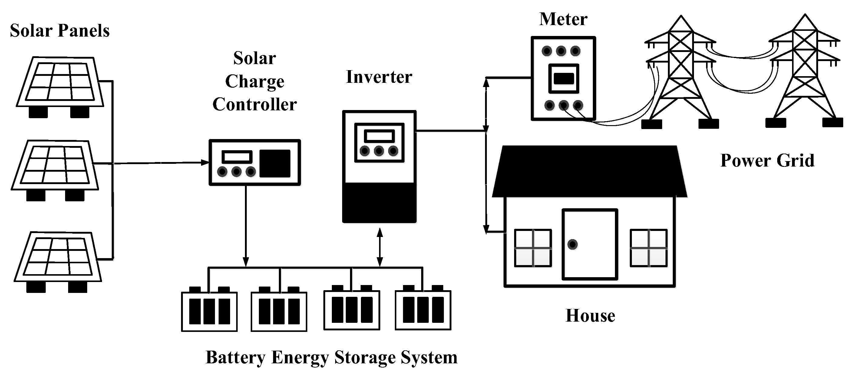
Figure 2.
Layer photovoltaic. .
Figure 3.
Inverter system on factory.
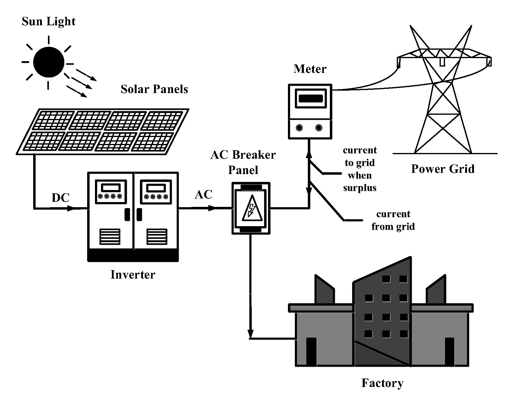
Figure 4.
Batteryless grid tiled inverter system.
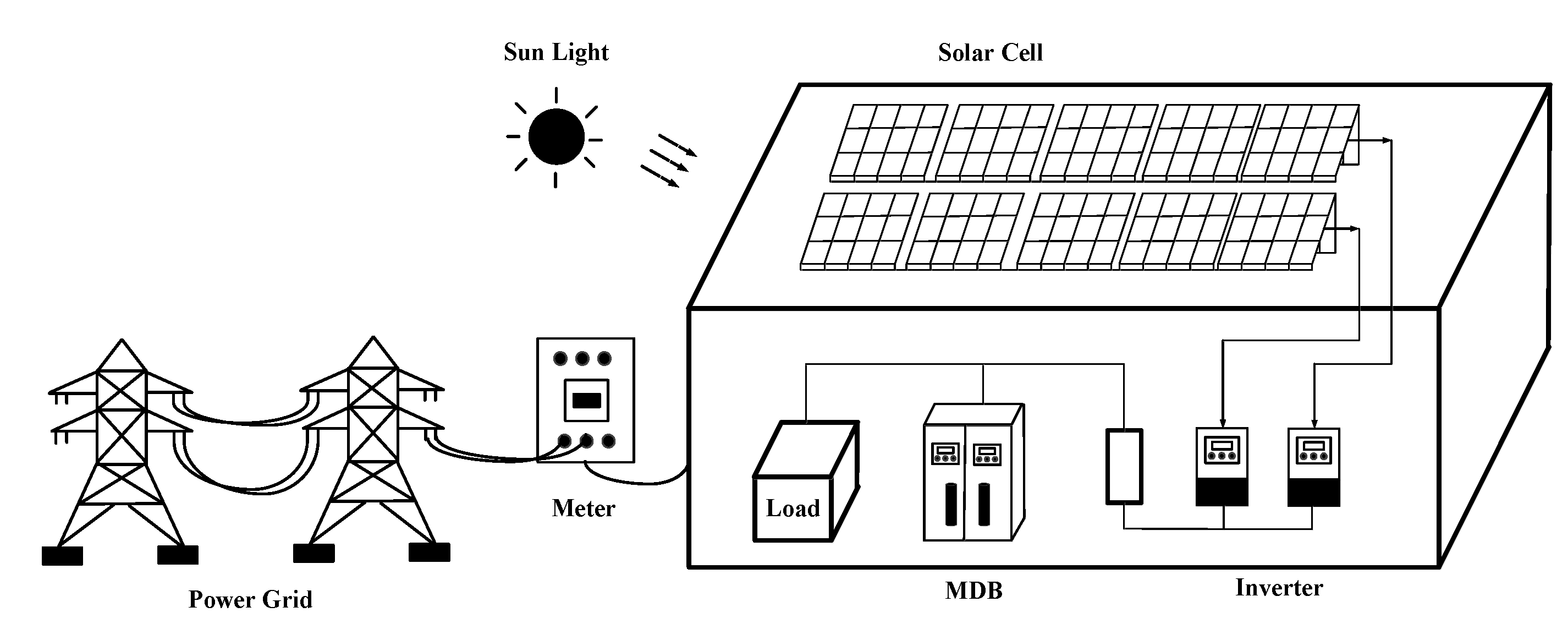
Figure 5.
Stand alone inverter.
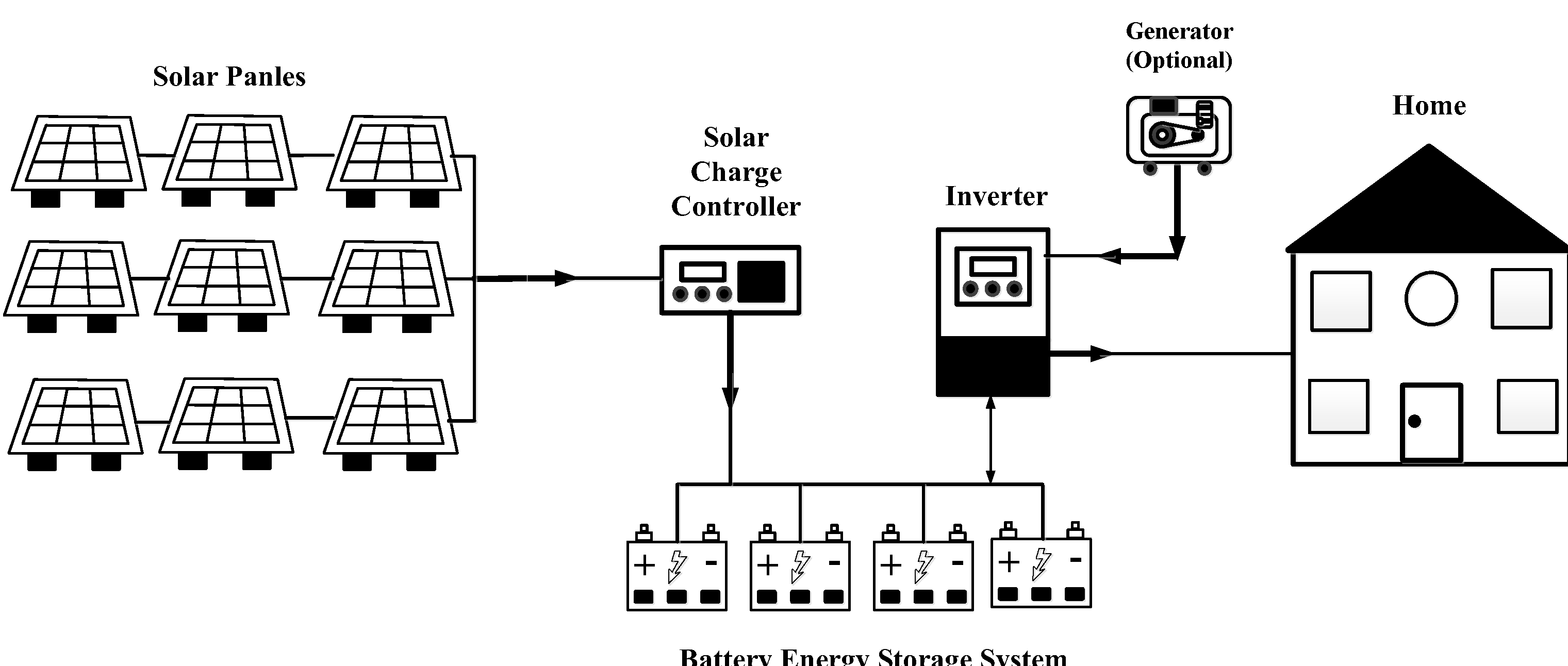
Figure 6.
Grid tiled with battery backup inverter system.
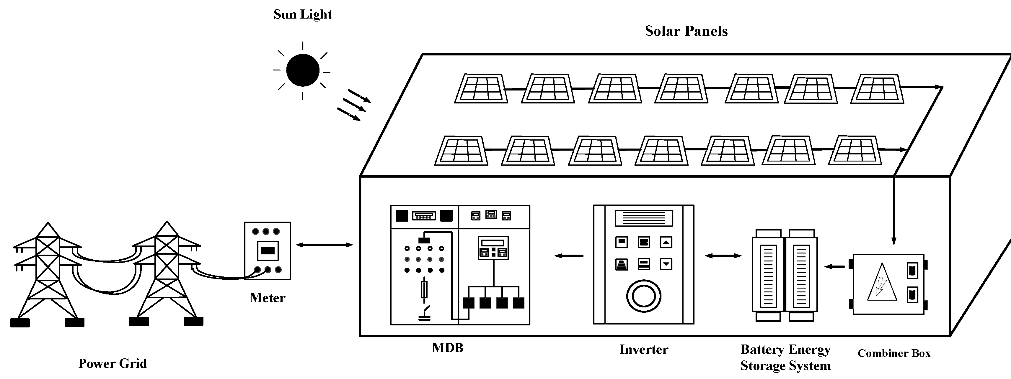
Figure 7.
Battery energy storage system on factory.
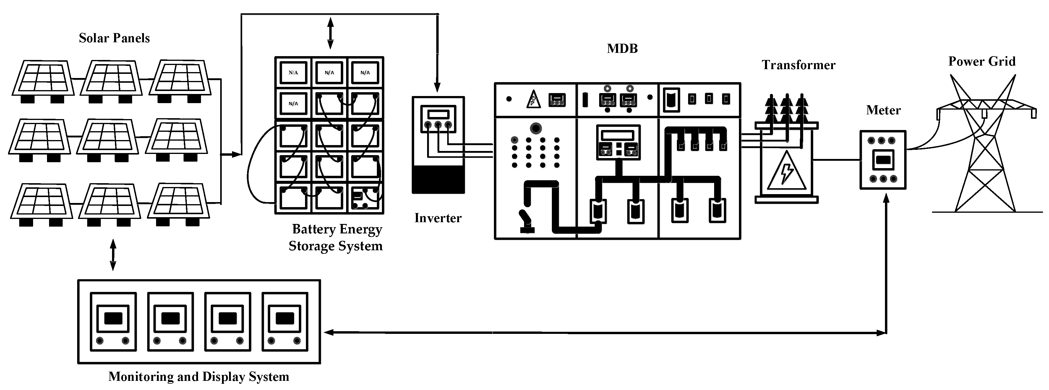
Figure 8.
Power distribution system.
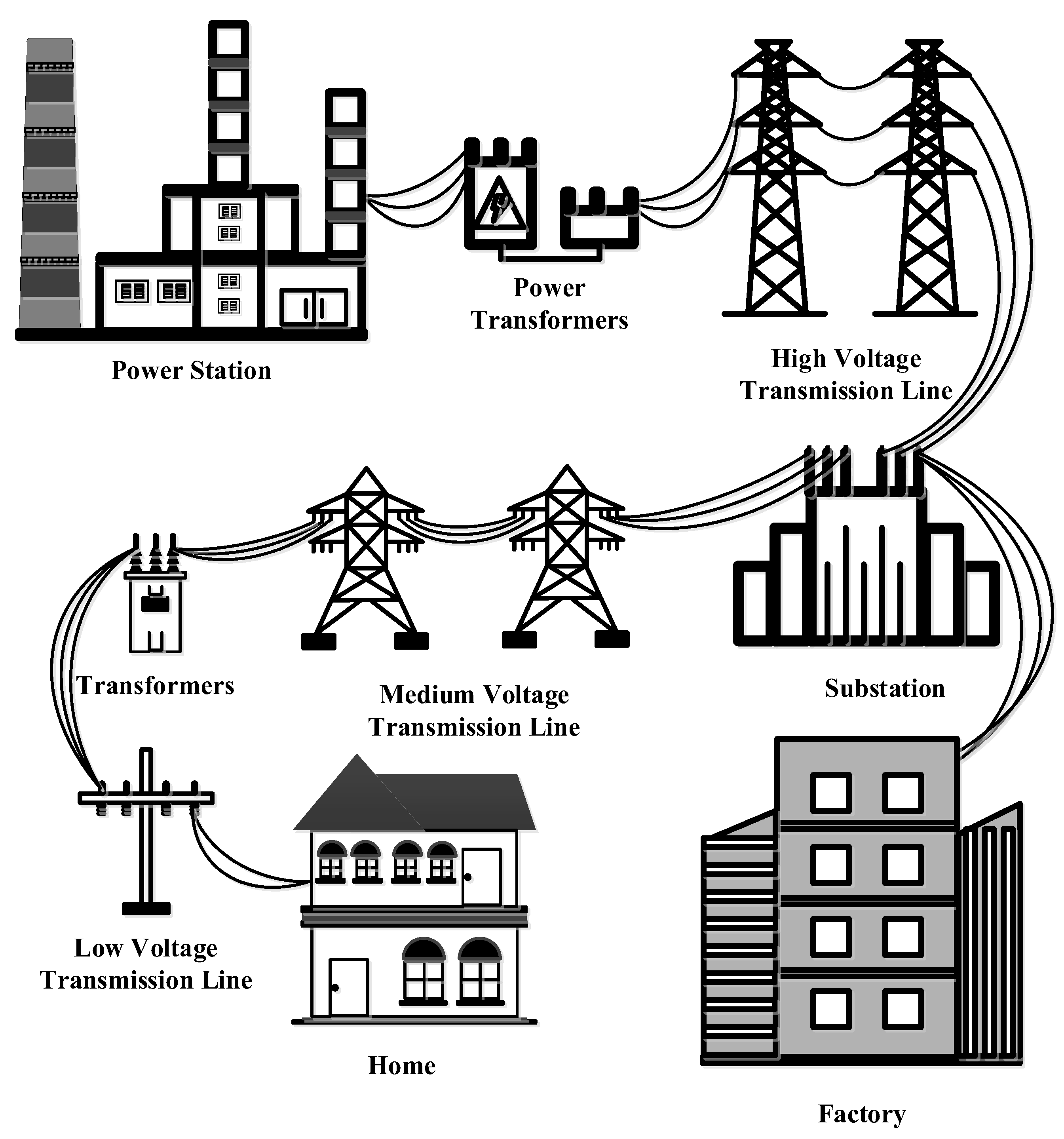
Figure 9.
IEEE 33 bus distribution system.
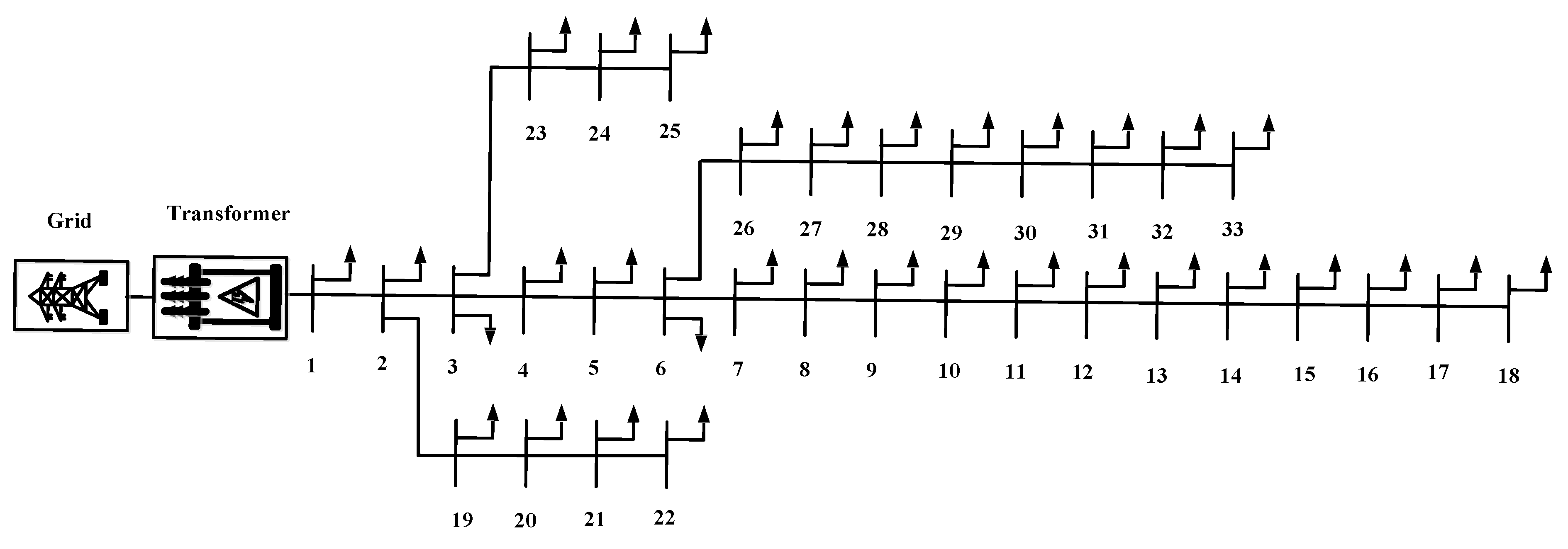
Figure 10.
Flowchart.
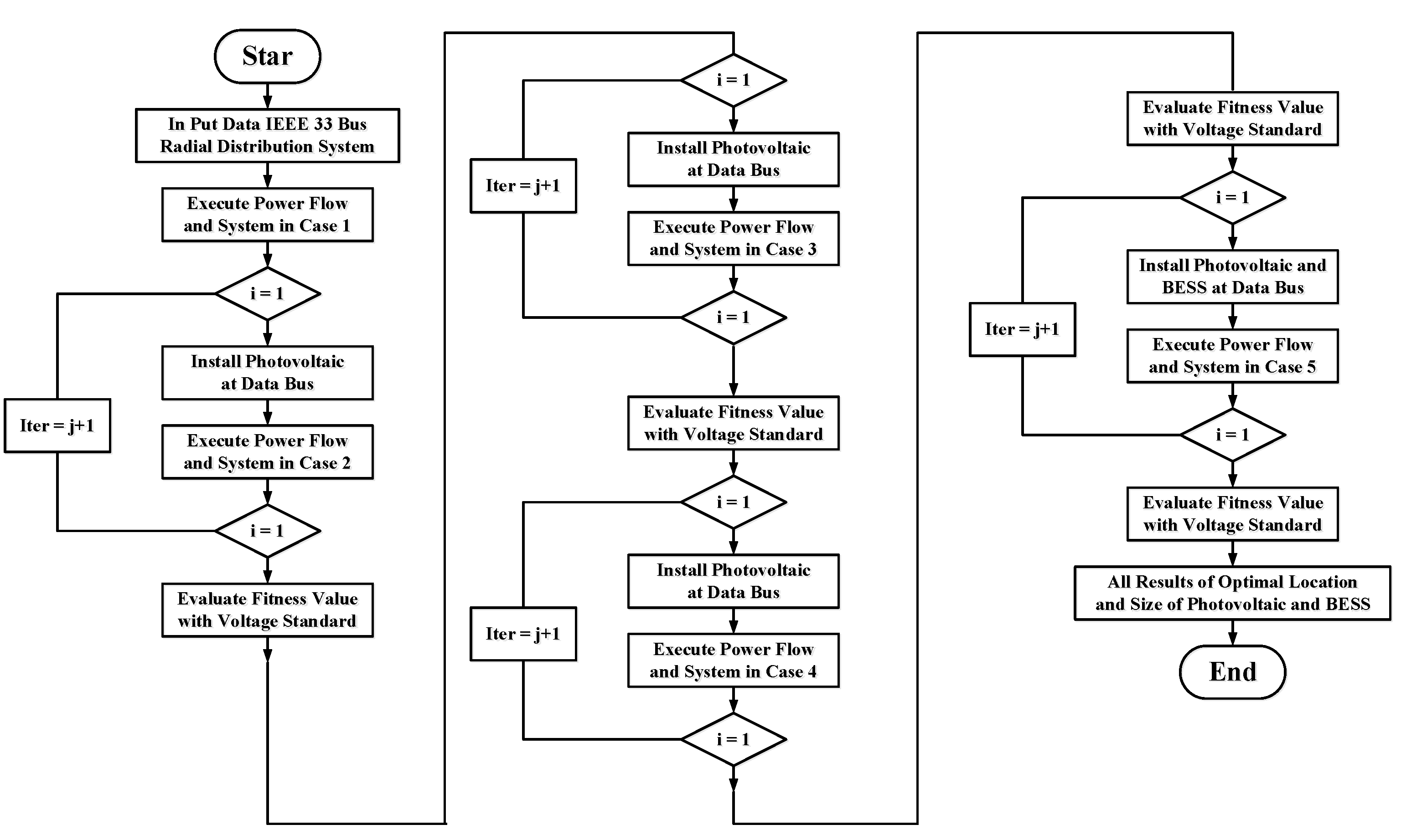
Figure 11.
Case 1 before installation photovoltaic and battery energy storage system.
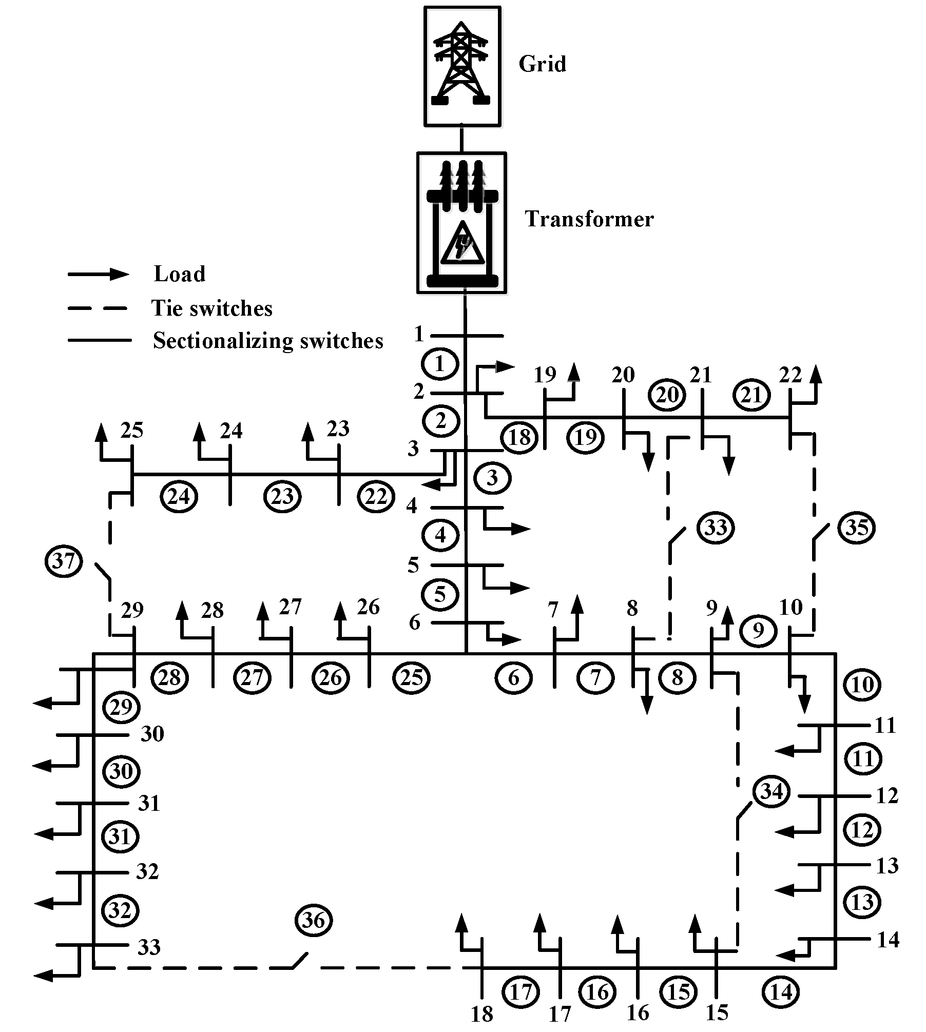
Figure 12.
Case 2 installation photovoltaic at bus 16, 18, 31 and 33.
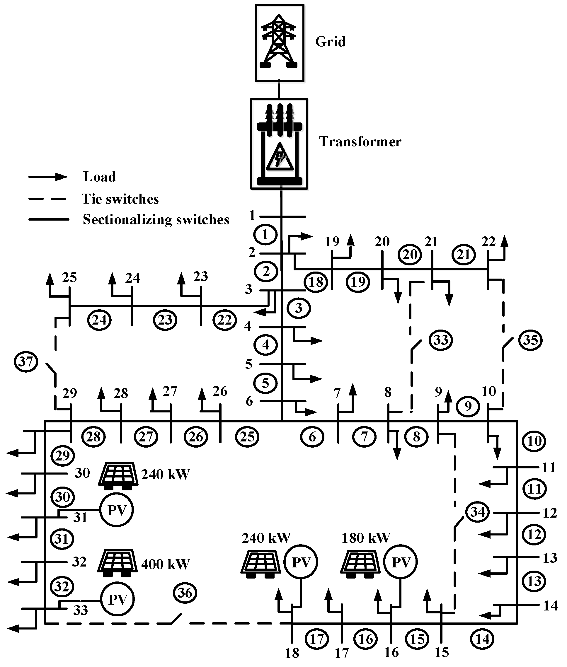
Figure 13.
Case 3 installation photovoltaic at bus 18.
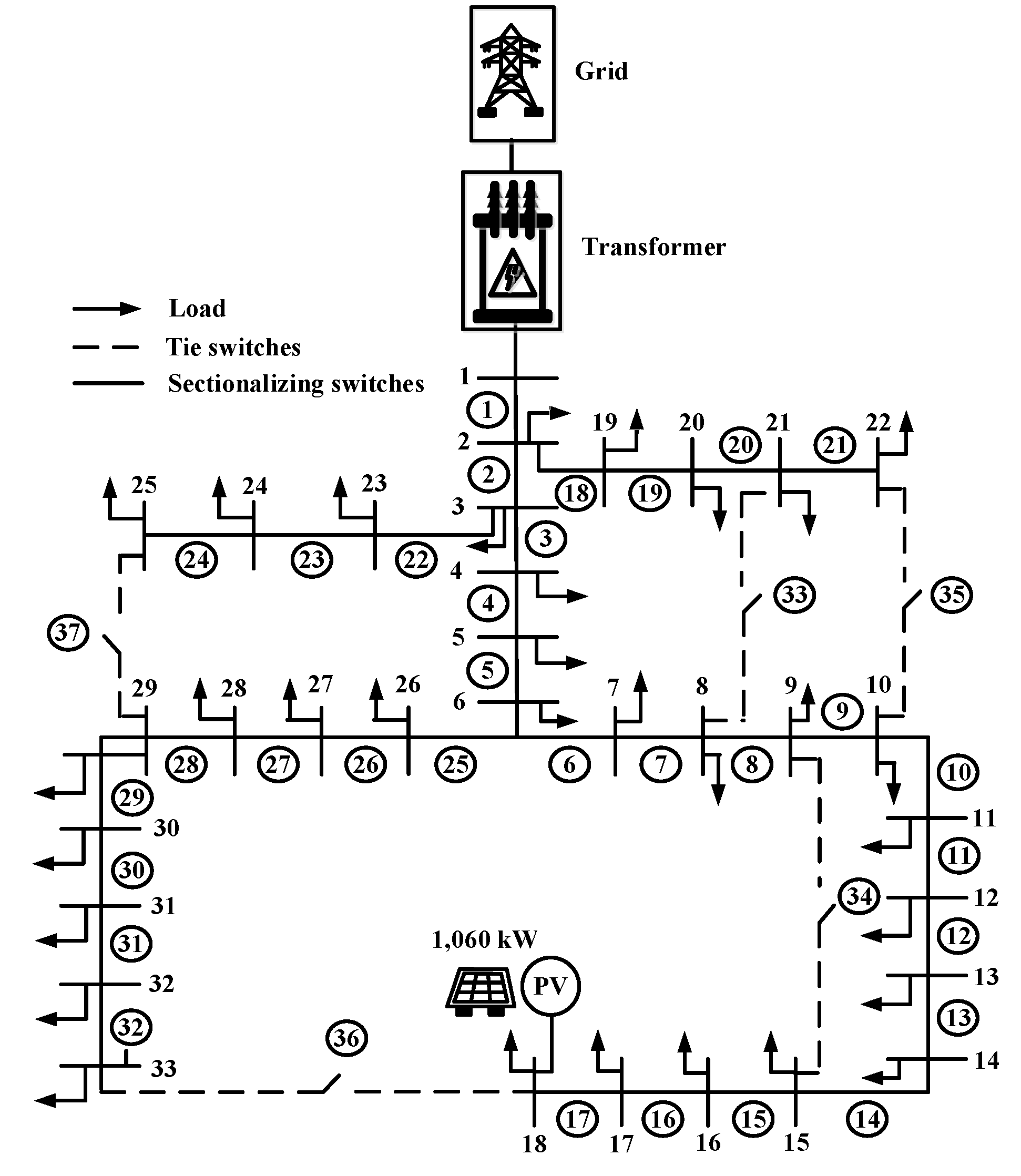
Figure 14.
Case 4 installation photovoltaic at bus 18 and 33.
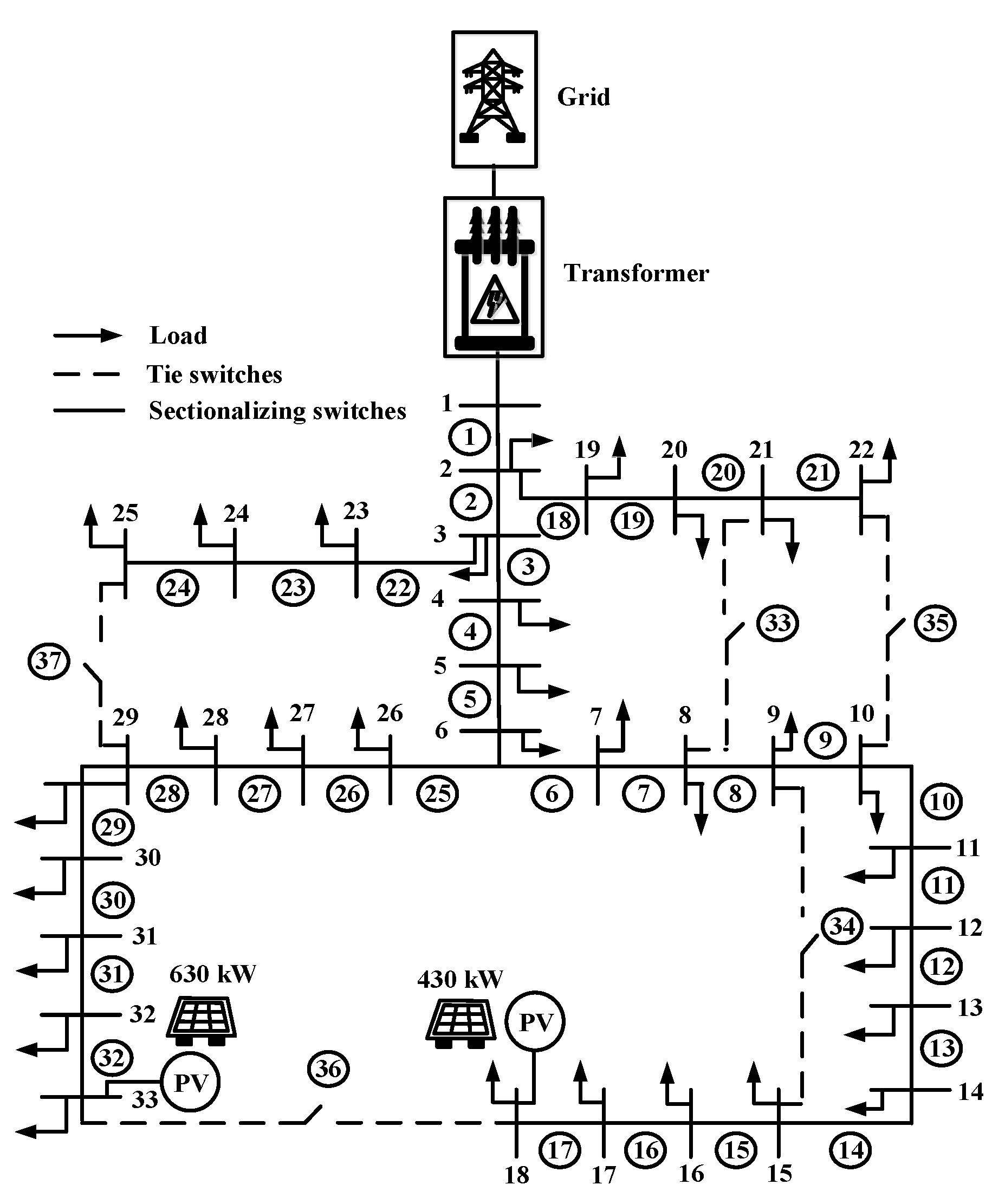
Figure 15.
Case 5 installation photovoltaic at bus 16, 18, 31 and 33and battery energy storage system at bus 14 and 29.
Figure 15.
Case 5 installation photovoltaic at bus 16, 18, 31 and 33and battery energy storage system at bus 14 and 29.
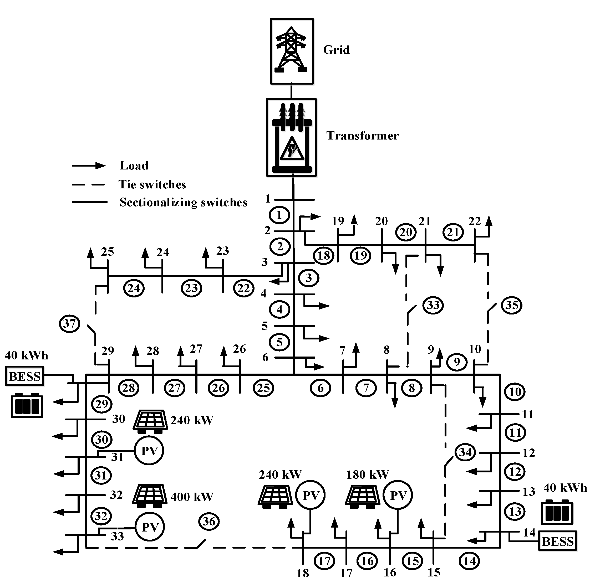
Figure 16.
Result adjustment voltage drop case 1 and case 2.
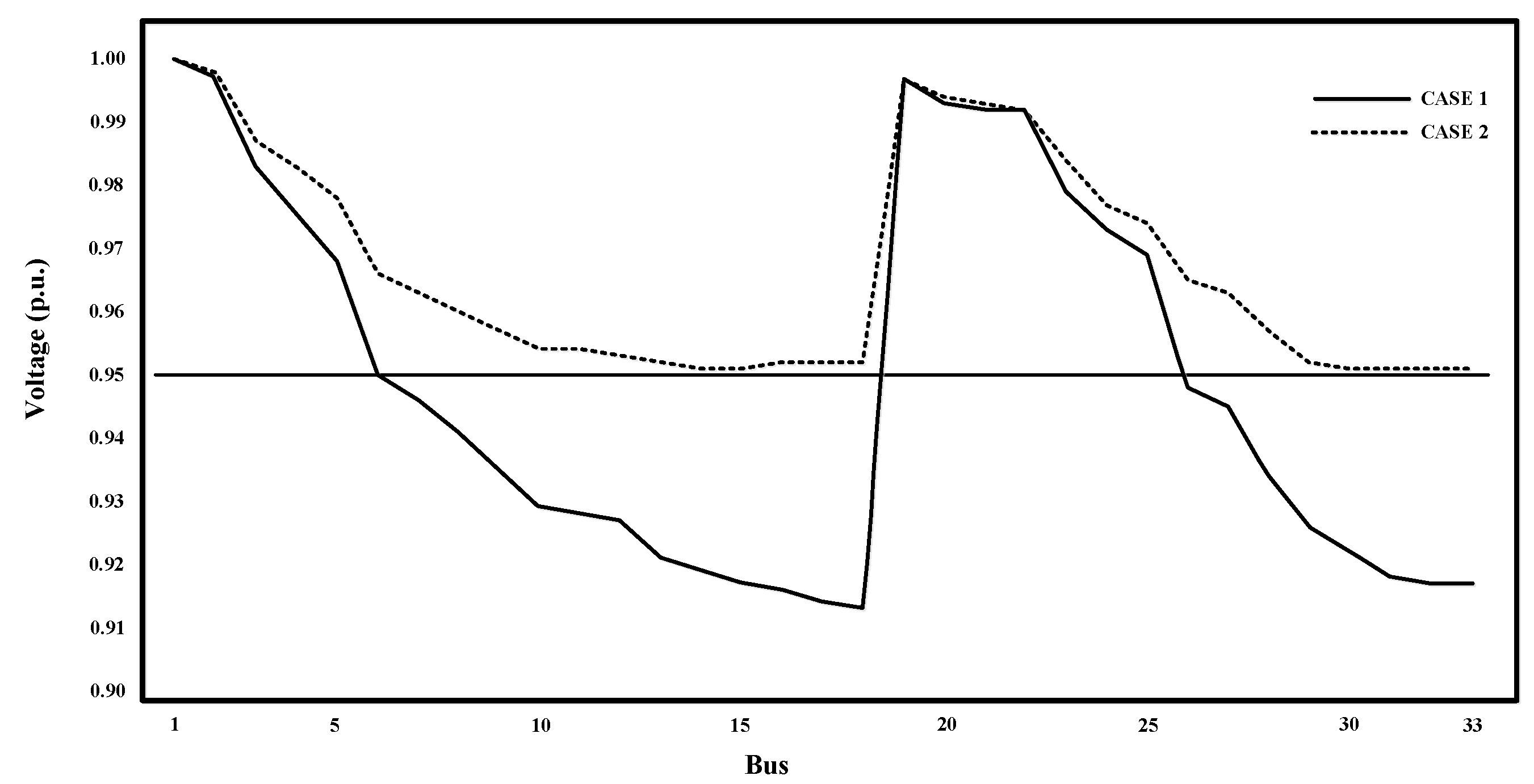
Figure 17.
Result adjustment voltage drop case 3, case 4 and case 5.
Disclaimer/Publisher’s Note: The statements, opinions and data contained in all publications are solely those of the individual author(s) and contributor(s) and not of MDPI and/or the editor(s). MDPI and/or the editor(s) disclaim responsibility for any injury to people or property resulting from any ideas, methods, instructions or products referred to in the content. |
© 2024 by the authors. Licensee MDPI, Basel, Switzerland. This article is an open access article distributed under the terms and conditions of the Creative Commons Attribution (CC BY) license (http://creativecommons.org/licenses/by/4.0/).
Copyright: This open access article is published under a Creative Commons CC BY 4.0 license, which permit the free download, distribution, and reuse, provided that the author and preprint are cited in any reuse.


