1. Introduction
Closed loop vertical ground source heat pumps are notably widespread for their efficiency and effectiveness compared to other ground source heat pump types like horizontal closed loop, direct exchange, open loop, and surface water ground source heat pumps [
1]. One of their key advantages is the compact footprint of the heat exchanger in the form of a borehole, which makes them especially suitable for residential areas with small plots and commercial buildings [
1]. They also ensure stable ground temperature and demand minimal pumping energy [
1]. However, the system does have drawback of requirement for a deep borehole drilling which contributes to a higher cost and challenges related to expertise in borehole drilling and proper implementation [
1,
2].
Typically, water (or a mixture of water and antifreeze in below-freezing soil conditions) circulates on one side of the ground source heat exchange system, while refrigerant circulates on the other side, directly connected to the heat pump. According to ASHRAE-Applications [
3], U-tube boreholes typically range from 100-150mm in diameter and have depths of 15-120 meters. U-tube borehole length can be further increased to 180m or more if the procedures for deep boreholes are followed. A U-tube containing the circulating fluid is inserted into each borehole, typically made of polyethylene with a diameter of 20-40 mm, although other pipe materials may also be utilized [
3].
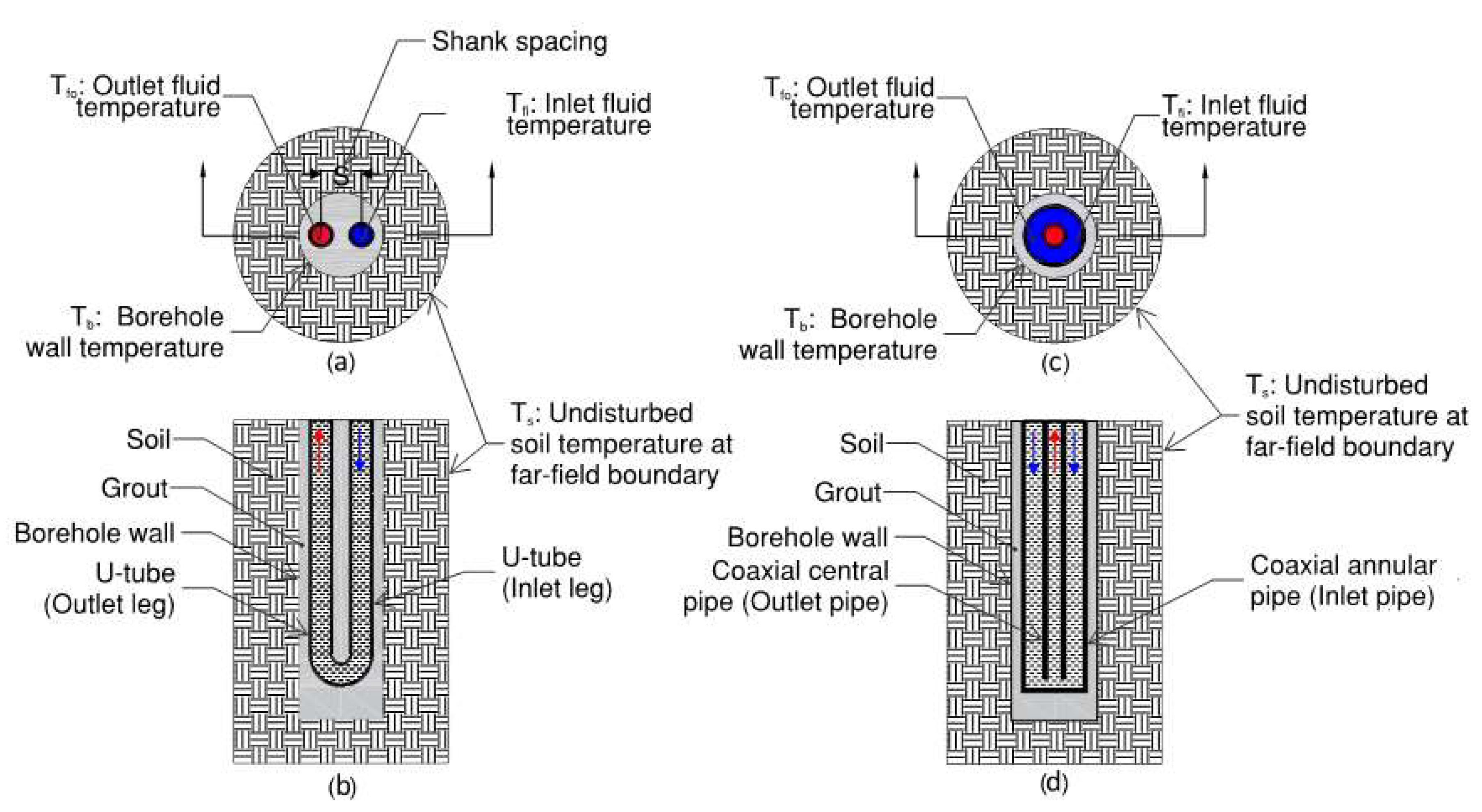
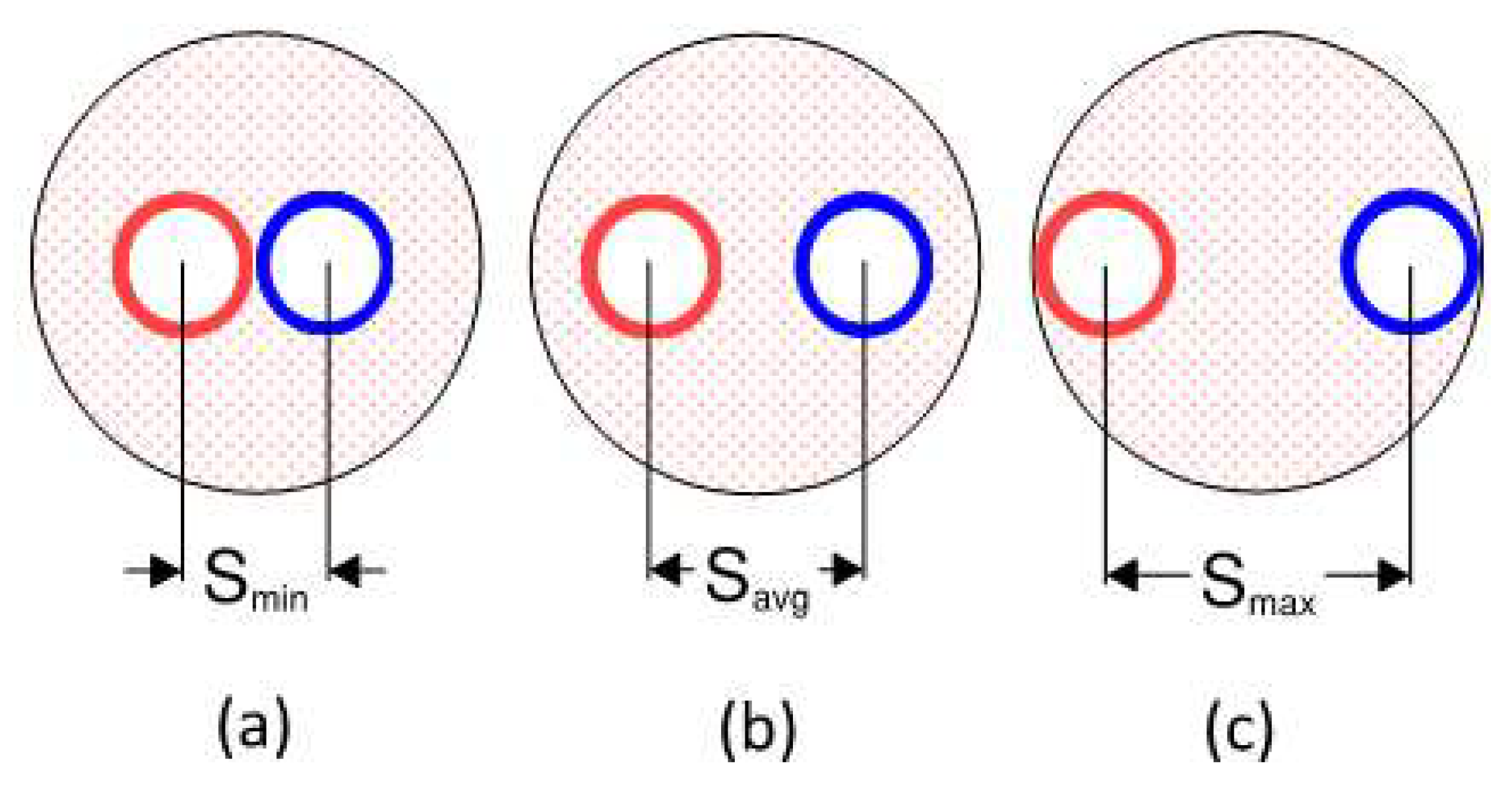
Figure 1(a) and
Figure 1(b) illustrate the U-pipe arrangement.
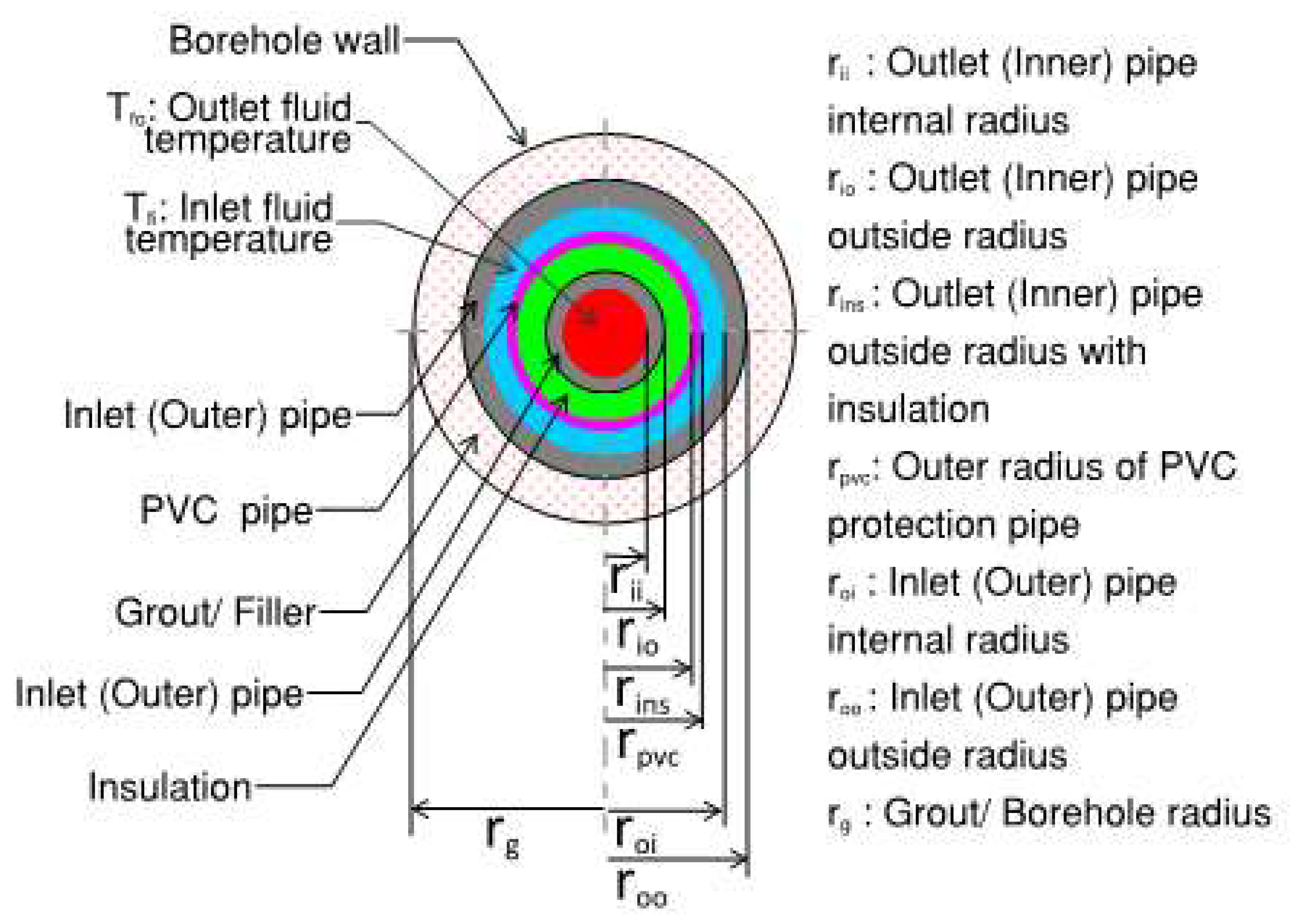
An alternative to U-tube boreholes is coaxial pipe arrangement where a smaller pipe (the inner pipe) is enclosed within a larger outer pipe. The heat transfer fluid can be circulated in two ways. One way is to enter the fluid through the outer pipe (inlet pipe) and return the fluid via inner pipe (outlet pipe). The other flow arrangement is to enter the fluid via inner pipe (inlet pipe) and return the fluid via outer pipe (outlet pipe).
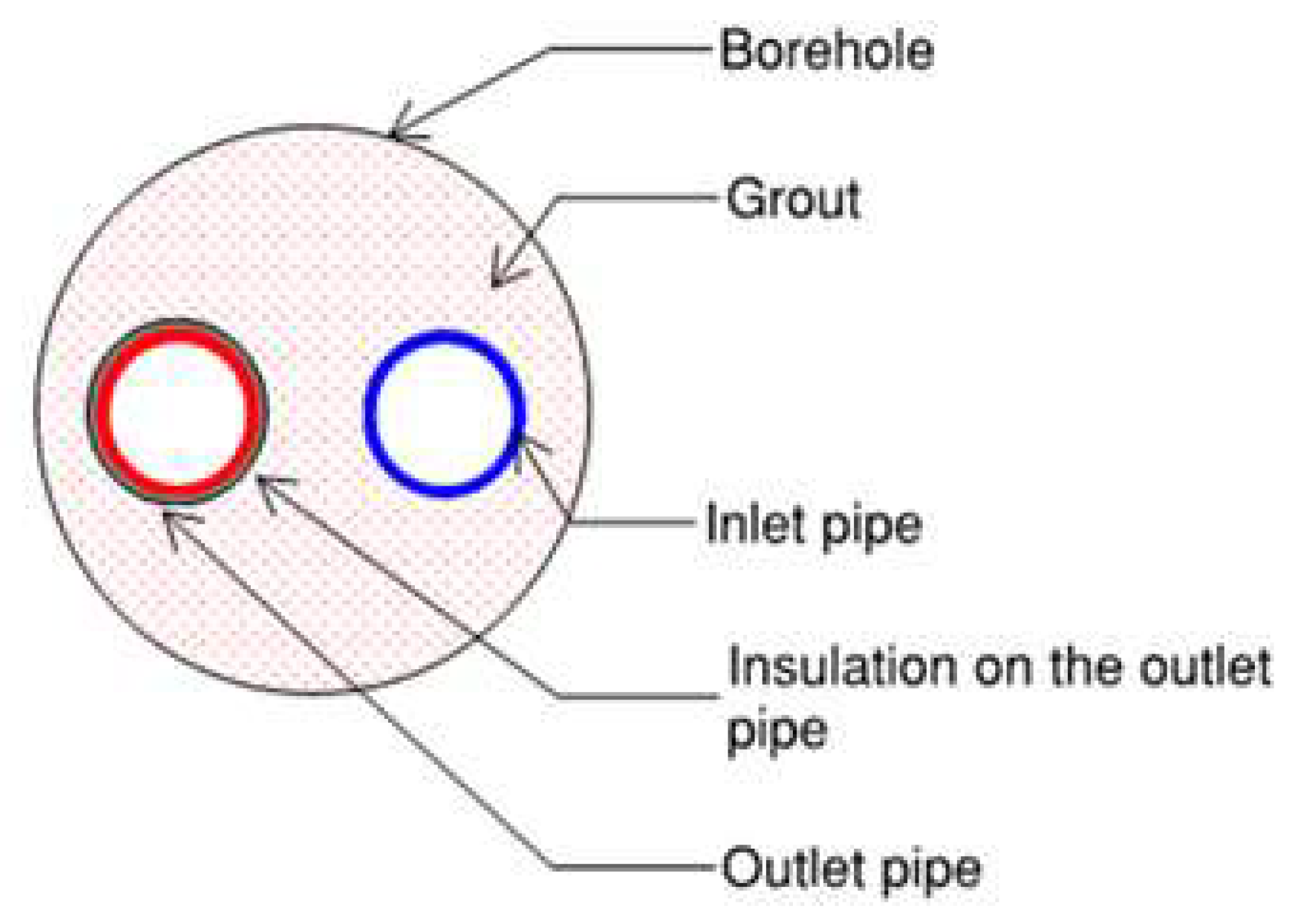
Figure 1(c) and
Figure 1 (d) illustrate the coaxial pipe arrangement with inflow through the annular pipe.
Usually the space between the U-tube/ coaxial pipe and the borehole wall is filled with grout, which serves a crucial role in stabilizing the U-tube/ coaxial pipe within the buried system and in preventing water seepage into the borehole. BHX cost (which is mainly the cost of U-pipe, grout and borehole drilling) for GSHP typically accounts for more than 30% of the total cost of the GSHP system [
4] Given its significant expense, optimizing this component is vital for enhancing heat transfer efficiency and for harnessing more sustainable energy from the same area of the land.
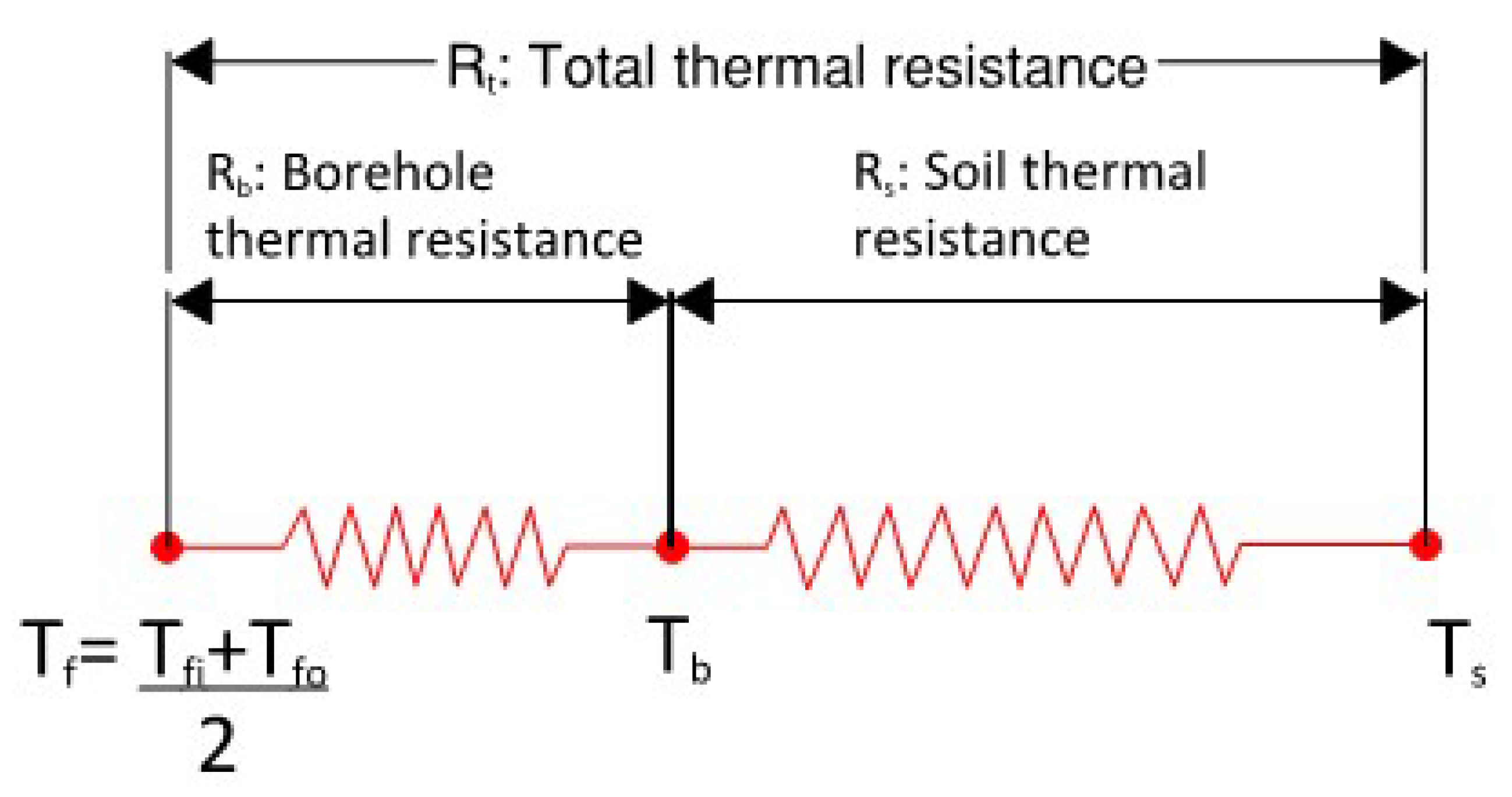
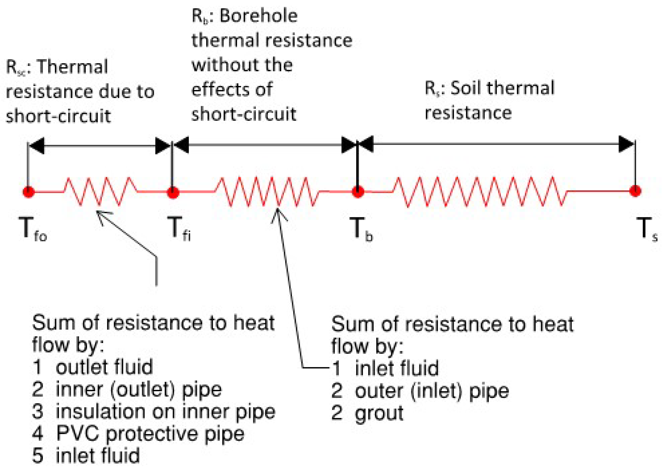
The total thermal resistance consists of two parts: the soil itself and the borehole as shown in
Figure 2. In a conventional U-tube BHX having a geometrical symmetry of the inlet and outlet legs, the fluid temperature to be considered for the evaluation of borehole thermal resistance is the mean temperature of the inlet and outlet fluid temperatures [
5].
The borehole resistance component includes the resistance offered by grout, pipe material, and the circulating fluid. Contact thermal resistance is assumed to be negligible for simplification. The total thermal resistance is the sum of soil and borehole resistance.
Reduction in any of the above two components or both will lead to an improved heat transfer. The heat transfer resistance characteristics of soil vary with geographic location and are generally immutable. Deep soil mixing offers a viable method to lower soil thermal resistance, yet its implementation is expensive and may not be economically feasible across all site conditions and soil types [
6]. On the other hand, there are methods to decrease Rb i.e., BHX thermal resistance. Therefore, the overall thermal resistance of the system can be reduced for an enhanced heat transfer by adopting techniques to lower the BHX thermal resistance.
Increasing the length of the ground loop in a BHX reduces the approach of BHX defined as the difference between average loop temperature T
f and the initial ground temperature T
s.
Reducing the thermal resistance between the ground and the circulating fluid enhances the heat transfer, thereby reducing the required length of the heat exchanger per kW for a given approach.
Previous research on the optimization of borehole thermal resistance has investigated the impact of pipe material, borehole diameter, shank spacing, and grout material. Research by Kerme et al. [
7] discusses various geometric factors (shank spacing, borehole size/diameter, borehole depth), grout and soil thermal conductivity for single and double U tube arrangements and then proposes the combined effective measures for heat transfer improvement. Shen et al. [
8] discusses the various influential factors (such as flow rate, inlet temperature, heat extraction rate, length of BHX and backfill material) on the performance of deep U-tube BHX and suggest an optimal control of flow rate.
According to Kavanaugh and Rafferty [
2] the choice of thermally enhanced grout material is also challenging. The grout filler must block surface water and unwanted groundwater from reaching aquifers, as they can pollute drinking or irrigation supplies. High-solids sodium bentonite grout (>20% solids), while effective, is a poor heat conductor, whereas materials with good heat transfer may allow water migration. Some regulations may permit porous materials if the top 6 meters of the borehole are sealed with a nonporous grout. Cement-based sealants are ineffective for BHX due to pipe shrinkage but can be enhanced with additives. Pouring of thermally enhanced grout with abrasive sand might also be challenging due to unavailability of the pumping equipment with the installer.
Erol and François [
9] studied various BHE grout materials, including bentonite-based, silica sand-based, and homemade admixtures with graphite. Increasing graphite content beyond 5% or using all types of graphite powders in BHE backfill mixtures is impractical, as graphite’s varying properties can negatively affect grout flowability, permeability, and strength. By TRT test, they found that adding just 5% homemade natural flakes graphite enhances grout thermal conductivity, crucial for optimizing heat transfer efficiency when matched appropriately to ground conductivity.
Study by Mahmoud et al. [
10] suggests that selecting the right grout depends on system conditions. Traditional grouts like bentonite and cement offer strength but require additives for better thermal performance. Phase change material (PCM) is recommended for its storage capacity and stability. A mix of conventional grouts, additives, and PCMs is recommended for optimal results.
Liu et al. [
11] conducted a comprehensive study to assess potential cost reductions through enhancements in borehole heat transfer under diverse geological and thermal conditions and revealed that improvements such as enhanced grout and double U-tube loops effectively reduce borehole lengths. The study primarily focuses on installation costs and relies on the simplified geometrical approach of Eskilson’s g-function through commercial software.
Research work is also available on comparison of U-tube with coaxial pipe and a few other arrangements like double U-tube, discussing the thermal behavior of the BHX with these arrangements. Study made by Zanchini et al. [
12] showed that in coaxial pipes, the configuration where water flows into the BHX through the outer annular pipe and exits through the inner pipe provides superior thermal performance compared to the opposite arrangement, where inflow occurs through the center or inner pipe and outflow through the outer annular portion. Brown et al. [
13] modelled coaxial, single U-pipe and double U-pipe configurations, finding coaxial pipes exhibiting highest heat transfer rate and lower pressure drop. Harris et al. [
14] demonstrated that the coaxial BHX configuration is more effective than the double U-pipe design. According to Chen et al. [
15], by using double U-tubes in parallel in BHXs, the heat transfer capacity may increase by over 50% from the single U tube system which could justify the cost increase in installation and pumping energy consumption. Chen and Tomac [
16] suggest use of VIT (Vacuum Insulated Tube) for coaxial pipe arrangement to prevent thermal short-circuiting. An economic analysis is suggested as the cost of VIT is 5 times more than the cost of un-insulated tubing.
While there is an ample research work available on the comparative study of materials and geometry of the U-tube BHX and its comparison with the other arrangements like coaxial pipes and double U-tube, there is not much research work on segregating the inlet and outlet leg of the U-tube to prevent them from a direct interaction with each other.
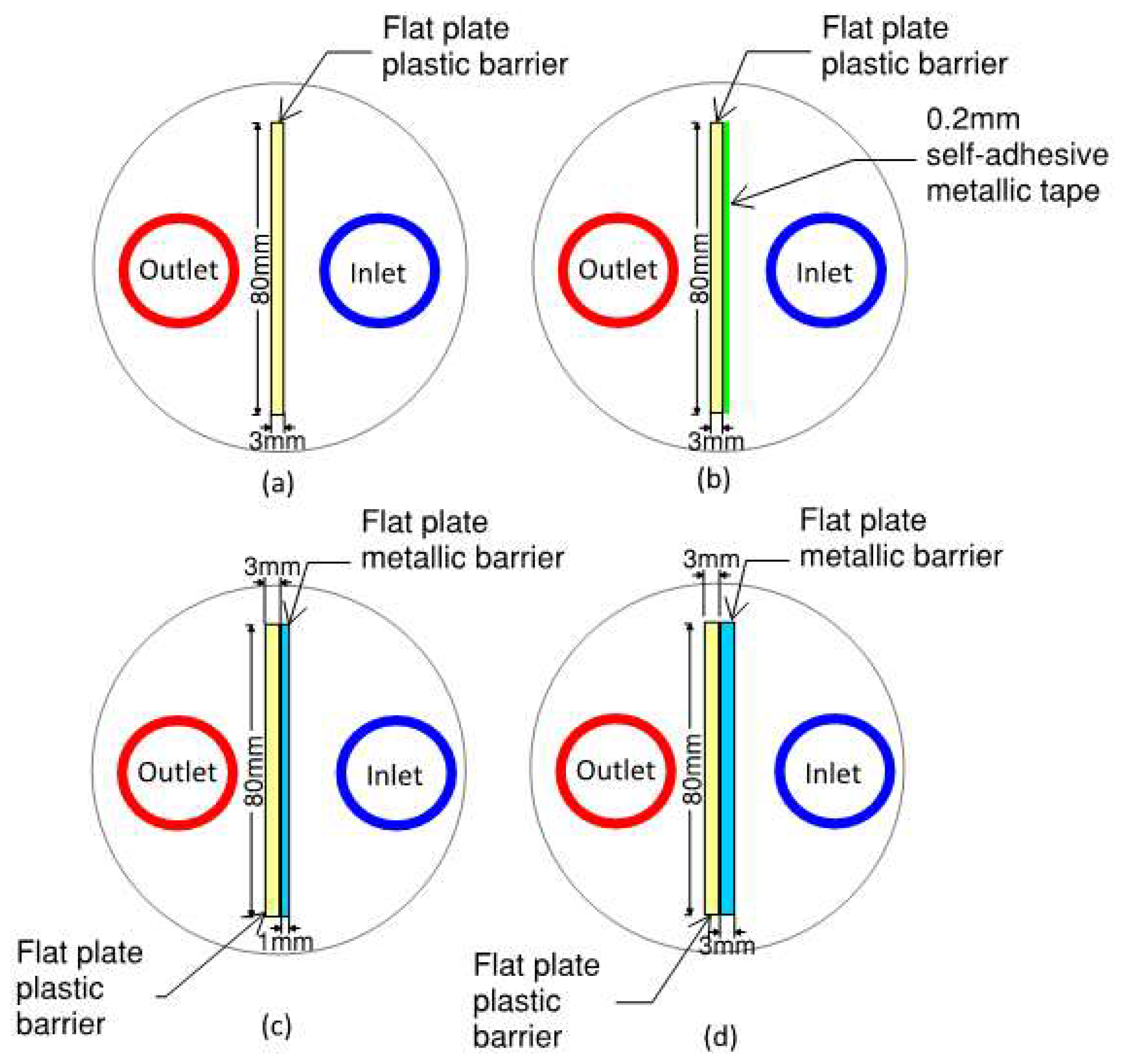
Al-Chalabi [
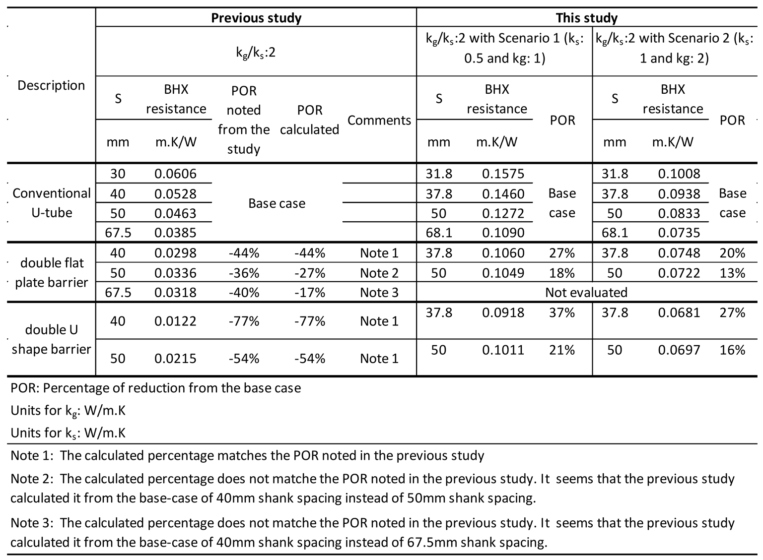
6] investigated the effects of introducing I-shape and U-shape obstructions in a U-tube BHX. However, the study did not account for the thickness of the U-tubes, which led to extremely overestimated efficiency of the barriers compared to scenarios where tube thickness is considered. In addition, the study is limited to the highly thermally conductive grout with a ratio k
g/k
s of 2, and does not provide an insight into the various alternatives of the grout and soil. The results are reported in terms of the borehole thermal resistance instead of an overall thermal resistance. High thermal conductivity grout results in a lower contribution of the BHX thermal resistance out of the total thermal resistance of the soil and BHX. Therefore, there is a need to report the net impact of the saving in terms of an overall reduction in the total thermal resistance or borehole length or an overall increase in the heat transfer.
Ngo and Ngo [
17] conducted a numerical assessment to evaluate the impact of an insulated flat shape barrier between the U-tube legs of ground heat exchanger. The study examines the effects of Reynolds number on heat transfer, focusing on laminar flow with a low Reynolds number value (optimal heat transfer at Reynolds number of 120 and suggests that at lower Reynolds number values, heat transfer increases due to a decrease in the outlet temperature (T
fo) for a given inlet temperature (T
fi), though it does not address the impact of reduced mass flow rate on the heat transfer as a result of lower Reynolds number value. The heat rejected by the fluid for cooling will be as follows [
2]:
The expression for Reynolds number is as follows [
18].
The above equation depicts that the mass flow rate of the fluid is a function of Reynolds number. Under the given geometry and fluid temperature, the Reynolds number varies directly proportional to the mass flow rate of the fluid, which means the more the mass flow rate, the more will be the Reynolds number for a given geometry and fluid temperature. In case of turbulent flow through pipes, the Reynolds number is ≥ 10,000 [
18]. Ngo study with Reynolds number of 120 will have a significantly lower flowrate through the same geometry than the flow conditions considered in other studies with turbulent flow. The study does not very clearly state the pipe material considered in the study, however mentions that their study reports high efficiency operation with 16% enhanced heat transfer when copper pipe is used instead of high-density polyethylene. It is therefore understood that they have conducted a study based on copper pipes. Previous studies suggest that use of HDPE pipes is very common due to better performance, durability and economics [
2,
19,
20,
21]. The assumption of copper piping with laminar flow within the U-tube could increase the risk of thermal short-circuiting than that with high density polyethylene pipe [
2]. Due to more short-circuiting, the results of improved heat transfer due to barrier between the inlet & outlet pipe will be misleading. Thickness of the pipe is also neglected which will overestimate the performance of the barrier. Because the study is not based on optimal parameters, there is a potential to increase the heat transfer further by improving the flow rate and pipe material. Measures to improve these parameters will result in a change in the reported impact of the barriers in the study, which warrants further analysis to draw definitive conclusions.
Previous studies about grout material have suggested that grout selection for better thermal conductivity might be challenging and may be compromised for the strength of the BHX and/or economy. The study of the novel technique of barriers between the two legs of BHX for optimization of heat transfer is required to be explored as an alternative to conventional way of increasing the heat transfer by thermally enhanced grout. The technique can also be applied in addition to the conventional methods to further increase the heat transfer. There is a need for a detailed evaluation of the thermal performance of the barrier between the two legs of a U-tube BHX, with a specific comparison to a conventional U-tube system. Due to complexity of the BHX geometry, numerical assessment would be more appropriate. Flat plate and U-shape geometries of the barrier are to be studied with various materials and thickness. The design parameters of BHX geometry and flow are to be optimized before evaluating the effect of barrier. Comparison to be made with a focus to depict the sole contribution of barrier from the base case. It is also required to report the results of an overall impact in terms of net increase in heat transfer or net reduction in the BHX length. This would allow for a clearer assessment of the barrier’s unique contribution in optimizing the BHX length and will help implementing the barrier technique where they contribute to the enhancement of heat transfer through the BHX. Additionally, it would be beneficial to compare the results of numerical assessment for barrier techniques with other heat transfer enhancement techniques, such as coaxial pipe arrangements, to offer a broader selection of borehole heat exchanger (BHX) design options.