Submitted:
17 November 2024
Posted:
18 November 2024
You are already at the latest version
Abstract
Efficient filtering in bio-signals acquisition is challenging. The resistance of the sources exhibits inter- and intra-subject variability or is unknown, thus using passive filters before the first amplification stage is problematic. Conversely, filtering after amplification does not effectively eliminate the amplified electrical noise, Main’s Interference, and the artifacts. In this context, the design and utilization of filters in the Analog Front End of biosensors, in conjunction with the first amplification stage, is not common but offers substantial advantages. In this study, the design of a novel Multi-feedback Differential Filter Instrumentation Amplifier (MFDFIA) is proposed. For addressing the aforementioned issues, the design and the equations governing the gain and bandwidth characteristics of the MFDFIA are presented and relevant topologies are explored. Even though MFDFIA has two op-amps in its first stage, due to its symmetric topology, the analysis can be conducted separately for the differential and common mode input signal with a simplified one op-amp equivalent circuit. Notably, MFDFIA’s CMRR is equal and depends only on the CMRR of the second stage. An exemplary application for EEG signal acquisition is provided, which has bandwidth 0.7 to 98.6 Hz, gain 50.3 db, power consumption 11.583 mW and 0.1-10 Hz noise 462.94 nVrms.
Keywords:
Differential Instrumentation Amplifier
; Filter Instrumentation Amplifier
; Bio-signals Acquisition
; EEG
; Analog Front End
; CMRR
; Multi-feedback Differential Filter
; MFDFIA
; Sensors
1. Introduction
1.1. The Medical Importance of EEG Technology
Electroencephalography (EEG) is a long-established method for monitoring the brain's electrical activity, primarily originating from pyramidal neurons in cortical layers IV and V [1,2]. Research is ongoing to detect subcortical electrophysiological activity using scalp EEG [3]. EEG is valued for its high temporal resolution, low cost, and non-invasive nature [1]. It typically involves scalp electrodes, but higher-quality signals can be obtained with intracranial EEG and Electrocorticography (ECoG), where electrodes are placed directly on the cortical surface [4]. EEG's strengths make it particularly useful for diagnosing epilepsy and other seizure disorders, as real-time electrical activity information is crucial [5]. It is also employed in diagnosing brain malignancies [6], CNS infections [7], sleep disorders [8], and other conditions. Beyond diagnostics, EEG is integral to Brain-Computer Interfaces (BCI), aiding those with movement and communication impairments and serving in research, entertainment, communication, and general well-being [9].
However, EEG has notable drawbacks, such as low spatial resolution [10], which only captures the synchronous activity of large neuron populations. Its low voltage (10-100 μV) and high susceptibility to noise, both physiological (e.g., EOG, ECG, pulse artifacts, EMG) and non-physiological (e.g., 50/60 Hz mains hum, electrode artifacts) [11], also pose challenges. Improving spatial resolution involves increasing electrode density and using source-localization algorithms [1]. Addressing noise and signal amplitude issues requires signal amplification and noise minimization to enhance the signal-to-noise ratio (SNR) [12]. The EEG signal comprises various neural oscillations, each with distinct frequencies and amplitudes. Filtering techniques, such as high-pass, low-pass, band-pass, and notch filters, are employed to isolate relevant frequencies and reject irrelevant noise [12]. These frequencies are categorized into bands corresponding to different brain states or activities. Traditionally, these bands included delta to beta waves (0.5-30 Hz) [11], but advancements in recording equipment and digital signal processing have expanded this range [13]. The frequency bands are:
- Infra-slow oscillations (<0.5 Hz), observed in preterm neonates and non-REM sleep [14].
- Delta waves (0.5-4 Hz), associated with deep sleep and found in infants and children [15].
- Theta waves (4-7 Hz), linked to drowsiness and early sleep stages (N1, N2) [15].
- Alpha waves (8-12 Hz), seen during quiet wakefulness, especially when eyes are closed [16].
- Beta waves (13-30 Hz), present during active concentration and task completion [16].
- Gamma waves (30-80 Hz), occurring in all brain states, prominent during alertness [17].
- High-frequency oscillations (>80 Hz), including ripples (80-250 Hz) and fast ripples (>250 Hz), related to memory encoding and cognitive process synchronization [18].
To reduce noise, instrumentation amplifiers with common-mode rejection and high differential signal amplification are utilized [19]. This work aims to integrate these concepts into a single analog circuit, enhancing the EEG measurement chain.
1.2. Problem Statement and Contributions of this Manuscript
Two aspects of great importance in EEG analog circuit design are signal amplification and filtering of unwanted signal components (e.g. noise, electromagnetic interference, artifacts). The typical design incorporates the amplification stage (usually by using an instrumentation amplifier, which also rejects some of the noise), before the filtering stage. This is done because the process of filtering also attenuates the signal, adding noise which would then be amplified along with the rest. By placing the filtering stage after the amplification stage, the issue is that the unnecessary signal components (e.g. 50 Hz mains hum) are also amplified. Thus, this technique is not a panacea, because the filters must handle the extra amplified added noise, and in general cannot cancel all the effects of noise amplification.
As an alternative, the initial filtering can be placed before the first amplification stage. In the particular case of biosignal acquisition this is deemed problematic, for the reason that the filters are usually in contact with the signal source that has variable impedance. The impedance of the signal source, which consists of the biological source plus the measurement electrodes, exhibits inter- and intra-subject variability or is unknown. Moreover, the way electrodes are placed appropriately on the measurement spot, the quality of the placement, the gel application and its durability in case of wet electrodes and the relative movement between the electrodes and the measured spots are factors that also affect the impedance of the measured system. This phenomenon makes the design of passive filters imprecise because their characteristics and filtering frequency are affected in real time by their contact with the measurement source.
Our design, by integrating a band-pass filter into the instrumentation amplifier, aims to accomplish simultaneous filtering and amplification, to mitigate the limitations of either aforementioned configuration and minimize the noise that remains in the signal.
2. Related Works
The integration of modern CMOS technology into EEG applications has significantly advanced the development of analog front-end (AFE) circuits. One notable advancement is the portable and compact EEG-signal amplifier that utilizes 90nm MOS capacitors with an AC-coupled input amplifier (IA) and a programmable gain amplifier (PGA). This design features a DC servo loop to minimize offset voltage, achieving high common-mode rejection ratio (CMRR) and gain, and it is developed using TSMC 90nm CMOS process to save space [20]. Another significant design includes the AFE for EEG with high impedance electrodes, integrating a low-noise amplifier (LNA) and high-pass filter (HPF) using a 3rd-order Butterworth filter. This configuration provides a gain of 37.05 dB while consuming just 6.5 µW from a 1V supply, making it ideal for battery-operated, wearable EEG devices [21]. For multichannel functionality, a 4-channel EEG AFE is proposed, incorporating buffers or current-to-voltage converters to accommodate various electrode types, with a chopper-stabilized amplifier reducing noise over 0.5 Hz to 2 kHz, and programmable gain for dynamic signal amplification [22]. Additionally, an AFE system with high input impedance and a chopper-stabilized amplifier reduces input-referred noise, crucial for detecting subtle signals in epilepsy and seizures over a broad bandwidth [23]. A reconfigurable AFE for local field potential (LFP) and action potential (AP) detection showcases high CMRR and mode-selectable gains, designed within a 180 nm CMOS framework for power efficiency in EEG applications [24]. Wireless advancements include a multi-channel EEG device using a Bluetooth microcontroller with configurable sampling rates, achieving a high signal-to-noise ratio (SNR) necessary for reliable recordings [25]. A design employing 32 independent, wirelessly powered devices enhances patient comfort for long-term monitoring [26], while a system using nRF52832 for Bluetooth-controlled multi-channel EEG data acquisition ensures efficient data transfer and low power consumption [27]. Innovations like current-reused Differential Difference Amplifiers (DDA) reduce power consumption and enhance accuracy for multiple biomedical signals [28]. Lastly, a low-noise chopper instrument amplifier designed specifically for EEG signals achieves an exceptional CMRR of 155.3 dB and PSRR of 167.5 dB, providing a stable platform for accurate brain activity monitoring [29].
Instrumentation amplifiers (IAs) play a crucial role in enhancing EEG AFE circuits by improving signal quality through two-stage amplification. A low-power constant-bandwidth analog front-end using current-reused differential difference amplifier (DDA) architecture offers high input impedance and CMRR, with adaptive biasing for consistent performance [30]. CMOS-based transconductance instrumentation amplifiers are designed for low power and high impedance applications, significantly reducing noise and DC offset to enhance signal integrity [31]. The capacitive-coupling chopper instrumentation amplifier (CCIA) exemplifies ultra-low power consumption at 0.36 μW per channel, using compressed sensing techniques to reduce data transmission demands while maintaining low input-referred noise [32]. Another promising design is a 45nm CMOS low-power, high-CMRR instrumentation amplifier with tunable gain from 31 dB to 52 dB, using AC-coupled feedback to enhance signal stability amidst physiological and environmental noise, consuming only 68 nW [33]. Recent developments include current feedback instrumentation amplifiers (CFIA) using 0.18 µm CMOS technology, achieving tunable gain and high CMRR through bandwidth-boosted folded cascode OP-AMPs [34]. High-gain temperature-compensated amplifiers manage environmental changes using dual-gain stages and class-AB output for improved stability and noise immunity [35,36].
Filters are essential in EEG analog front-end circuits, reducing noise and artifacts while isolating desired brain signal frequencies. A temperature-compensated instrumentation amplifier and filter minimize thermal drift and maximize SNR, ensuring reliability across diverse conditions [37]. A fourth-order low-pass filter using Complementary Super Source Follower (CSSF) technology maintains a dynamic range of 63 dB and an input-referred noise of 36 µVrms, operating on just 12.6 nW [38]. Additionally, a Resistive Random Access Memory (RRAM)-based low-pass FIR filter with a 40 Hz cutoff and chopper-stabilized amplifier minimizes flicker noise and reduces output signal distortion while consuming approximately 13 µW [39]. An 8-channel ambulatory EEG IC uses a dual-path feed-forward method for real-time motion artifact cancellation, achieving 41.5 dB artifact suppression and a gain of 48.3 dB at 55 µW per channel [40]. A low-pass filter designed with Continuous Current Conveyor II Plus (CCCII+) technology and a 100 Hz cutoff optimizes real-time EEG signal processing, significantly enhancing noise handling and signal integrity [41].
Filter instrumentation amplifiers enhance EEG signal accuracy and reliability by filtering unwanted frequencies and amplifying desired signals. A high-gain (101.61 dB) and high CMRR (147.68 dB) instrumentation amplifier employs a three-op-amp configuration with telescopic cascade stages and RC Miller compensation for stability, consuming 38.88 µW [42]. A chopper-stabilized amplifier designed for capturing low-frequency EEG and ECG signals features tunable MOS capacitors that finely adjust the low-pass filter's corner frequency, maintaining high selectivity and minimal distortion with a CMRR of 105.6 dB and noise levels of 120 nV/√Hz, with total power dissipation at 855 nW [43]. Further advancements include a CMOS-based chopper instrumentation amplifier minimizing flicker noise, providing robust performance in clinical settings [44]. The chopper-stabilized CFIA optimizes the noise efficiency factor (NEF) to 1.75, reducing offset and noise through nested chopping techniques [45]. Second-order characteristic preamplifiers suppress low-frequency interference, achieving high input impedance and CMRR for precise physiological signal measurements [46]. Fully differential two-stage CMOS amplifiers paired with third-order Butterworth filters enhance noise handling in EEG systems [47]. A high-gain, high-CMRR instrumentation amplifier tailored for biomedical signal acquisition uses a three-op-amp topology to enhance noise rejection and stability, including active low-pass filtering to suppress high-frequency noise, crucial for maintaining EEG signal integrity [48].
3. Design of Novel Multi-Feedback Differential Filter Instrumentation Amplifier Topology
In this study, the design of a novel differential instrumentation amplifier combined with a multi-feedback filter is proposed. The present design combines the stage of filtering and amplification. The novelty of this paper lies in solving the drawbacks of having the first filtering stage right before or after the first amplification stage. In case of passive filters, the disadvantages of placing a filter before the amplification is that the resistance of the source exhibits inter- and intra-subject variability or unknown and especially in biological signal acquisition settings usually it is not stable. Thus, the characteristics of the passive filter will change and it cannot be placed on the input, if precision is desirable.
The disadvantages of placing a filter after the amplification is that frequency ranges that can cause noise are amplified, and filtering cannot cancel the totality of the presence of the amplified noise. Thus, a novel approach of tackling the above problems is utilizing a multi-feedback filter. This is a type of electronic filter that uses multiple feedback elements for signal processing. A differential filter is a type of filter that is based on the principles of differential amplification. It is typically used to isolate, amplify, or filter the signal that differs between two inputs or between an input and a reference. In this novel design the fusion of the above type of filters is proposed to create a novel Multi-feedback Differential Filter Instrumentation Amplifier.
3.1. A Novel Construction of a Multi-Feedback Differential Instrumentation Amplifier Filter Topology (MFDFIA)
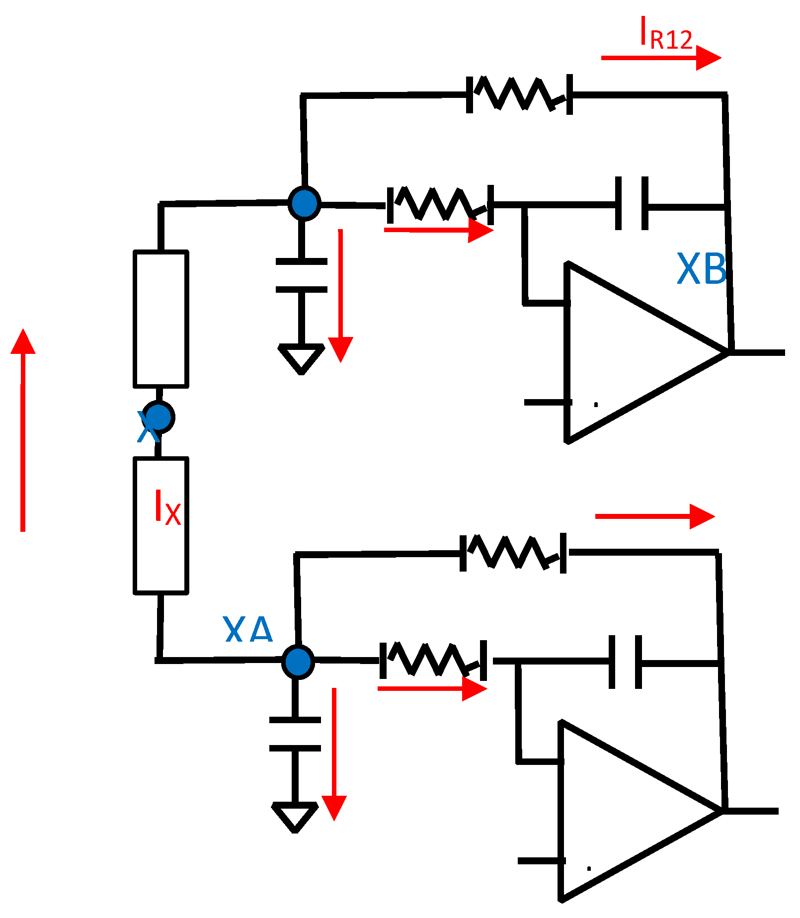
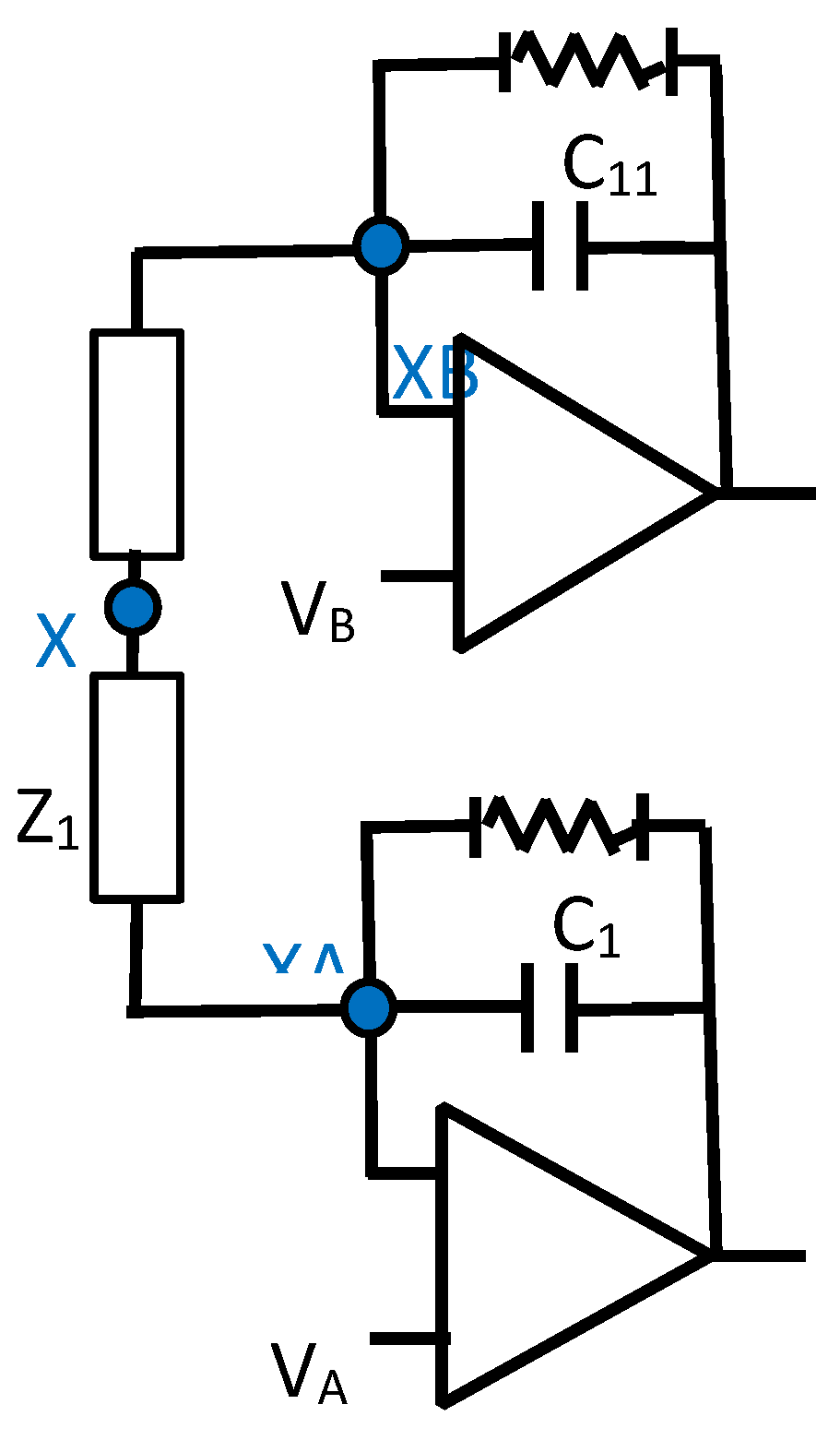
The implementation of this novel MFDFIA is achieved with the incorporation of a Multifeedback Filter. In particular, two symmetrical filters are constructed, one for each input, that produce the differential output of the first stage of the Instrumentation Amplifier. The symmetry is apparent with respect to the middle point between the impedances Z as can be seen in Figure 3.1.1. In order to get the largest rejection of the common signal, an absolute symmetry in the circuit is necessary, which depends upon the component values and their tolerances. This mandate is achieved with precision resistors and type I capacitors (C0G/NP0). The prices of this specific type of capacitor set a limit to the capacity that can be chosen to less than μF.
Figure 3.1.1.
The circuit of the MFDFIA.
- The gain of MFDFIA:
For further details on how those equations were constructed refer to Appendix A. Notice that component numbers have already been replaced by the corresponding lower index numbers due to symmetry and equal values.
From the transfer function it appears that we have a circuit which always has at least gain equal to 1 (0dB) and it will never act like a real filter, due to the constant unity in the transfer function (non-inverting amplifier topology that give rise to a unity constant in the transfer function), which dominates in high frequencies. However, the rest of the transfer function presents a form which acts like a filter with the following characteristics:
- A total DC gain
- 1st degree High Pass filter
- and a 2nd degree Low Pass filter
The above analysis identifies the behavior of the circuit in terms of the difference of the output voltages to the difference of the input voltages. However, it is not clear what happens to the common and differential signal.
3.2. Simplified Analysis of the Multi-Feedback Differential Filter Instrumentation Amplifier
Common Signal Gain
Studying the behavior of the circuit for the common signal, it can be stated that for , due to circuit symmetry, the corresponding nodes share the same voltage. More specifically, the voltages at the inputs of the operational amplifiers are equal:
Also due to symmetry and equal inputs we have
Since nodes XA and XB of the circuit in Figure 3.1.1 share the same voltages the current IX equals zero, so the Z branch is an open circuit.
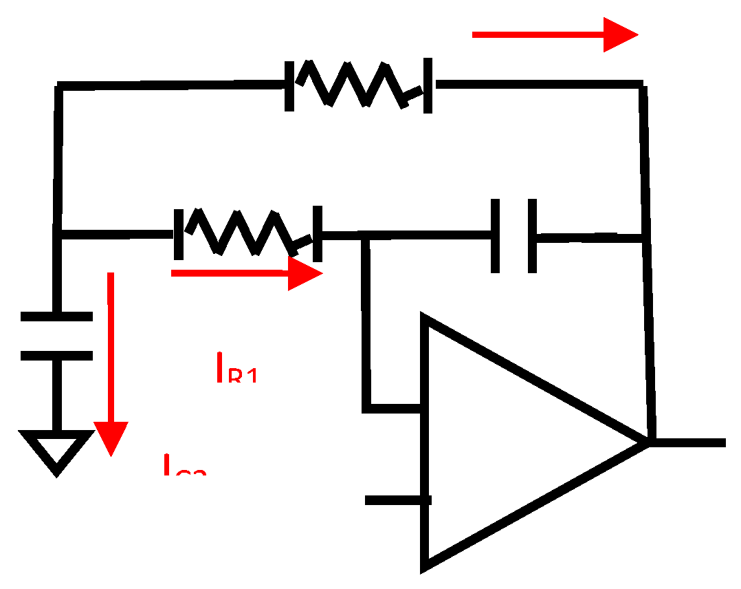
This fact allows the removal of the branch between nodes XA and XB, so the circuit simplifies as seen in following figure:
Figure 3.2.1.
The equivalent circuit of the MFDFIA for common signal.
The common signal transfer function is the following:
For further details on how those equations were constructed, refer to Appendix B.
From the transfer function, excluding unity constant, it appears that we have:
- No total DC gain
- 1st degree High Pass filter
- and a 2nd degree Low Pass filter
Differential Signal Gain
Studying the behavior of the circuit for the differential signal, it can be stated that for , due to circuit symmetry, the corresponding nodes have the opposite voltage. More specifically, the voltages at the inputs of the one operational amplifier are opposite from the inputs of the other operational amplifier.
So due to symmetry we have .
Since nodes XA and XB of the circuit in Figure 3.1.1, have opposite voltages and the current flows through two equal resistors (Z1,Z11), it is concluded that the voltage will be zero in the middle point (node X).
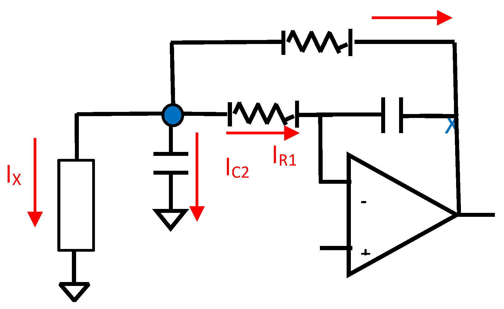
This fact allows the "cutting" of the aforementioned circuit at this node so the circuit simplifies as seen in following figure:
Figure 3.2.2.
The equivalent circuit of the MFDFIA for differential signal.
For further details on how those equations were constructed. refer to Appendix C.
From the transfer function, excluding the unity constant, it appears that we have:
- A total DC gain
- 1st degree High Pass filter
- and a 2nd degree Low Pass filter
3.3. Conclusions and Examples of the Simplified Analysis
It is noticed that any branch such as the Z’s branch, from the region of the negative input of one operation amplifier to the region of the negative input of the other operational amplifier, does not affect the common signal, regardless of the complexity of the circuit.
As for the common signal, it is also noticed that connecting any component such as the capacitor C2 to ground, creates a current flow from the output to GND and therefore a voltage drop across node X, thus forcing the output Vcom_out to rise in order to compensate this voltage drop, so there will be common signal amplification.
The gain of the differential signal depends on the Z resistor and the capacitor connected to the ground C2, which are in parallel connection.
The circuits proposed in this work are simulated using the LTSPICE software. The input signals in the simulation were chosen with the rationale that the circuit is designed to expect input signals from a few mV to a few hundred mV. The resistance in the signal generation part of the circuit is noiseless so the noise can be added specifically when it is relevant to the simulation. It must be also stated that when acquiring the signal, the circuit in principle cannot differentiate the signal that comes from inside the brain from the noise induced electrodes.
The circuit works as a proof of concept and thus generally, it is not mandatory to follow the exact values of the circuit components. The proposed values were chosen having in mind the incorporation of the circuit in a potential EEG AFE signal acquisition system.
Example of a Low-Pass Differential Filter
The AC Analysis of the filter was performed using the following SPICE model:
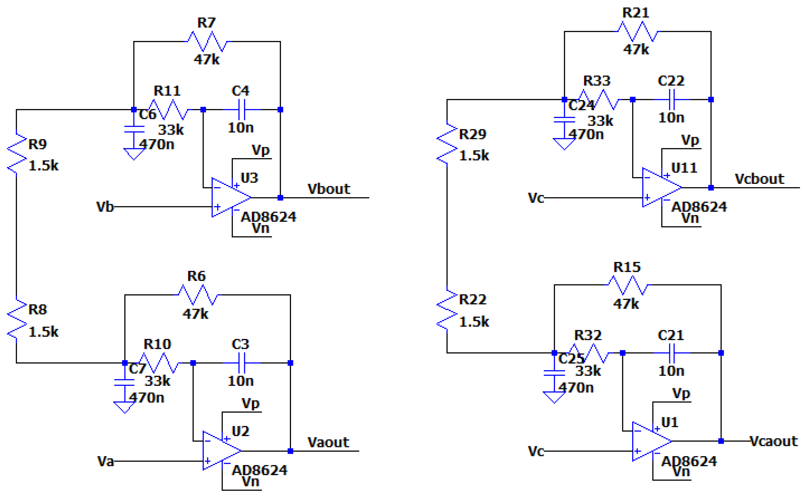
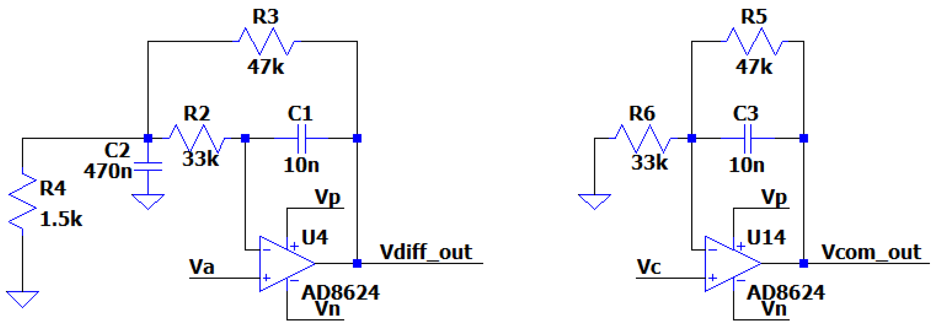
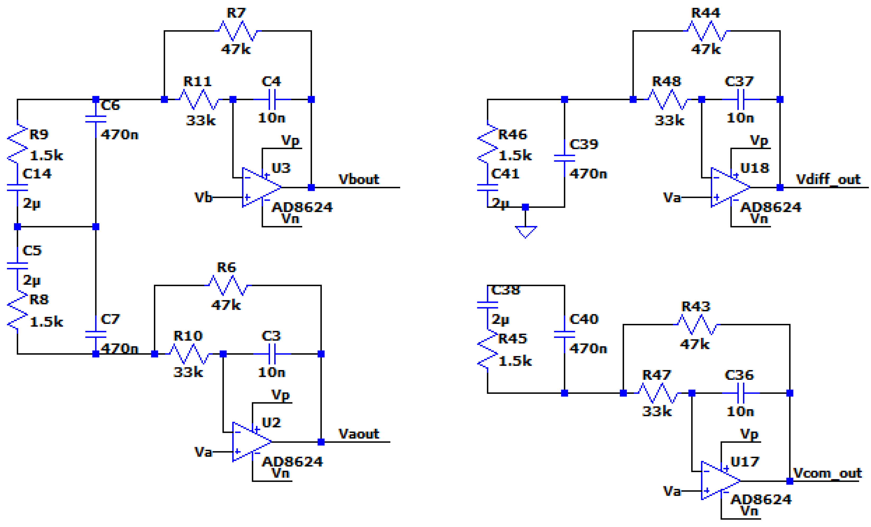
Figure 3.3.1.
The circuit of the MFDFIA with Va, Vb, simulating the differential signal and Vc simulating the common signal.
Figure 3.3.1.
The circuit of the MFDFIA with Va, Vb, simulating the differential signal and Vc simulating the common signal.
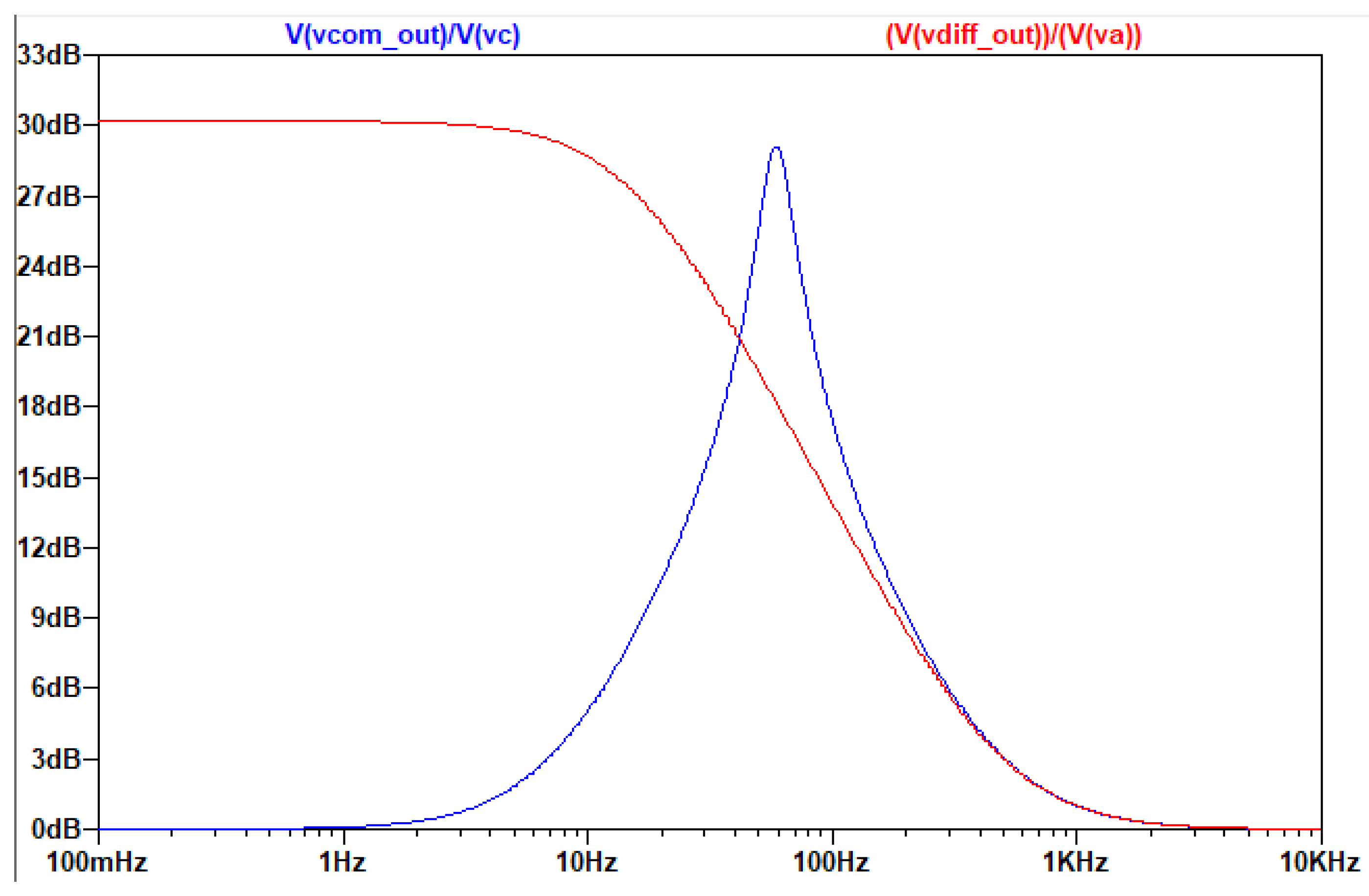
The output of the AC analysis is seen in the following figure:
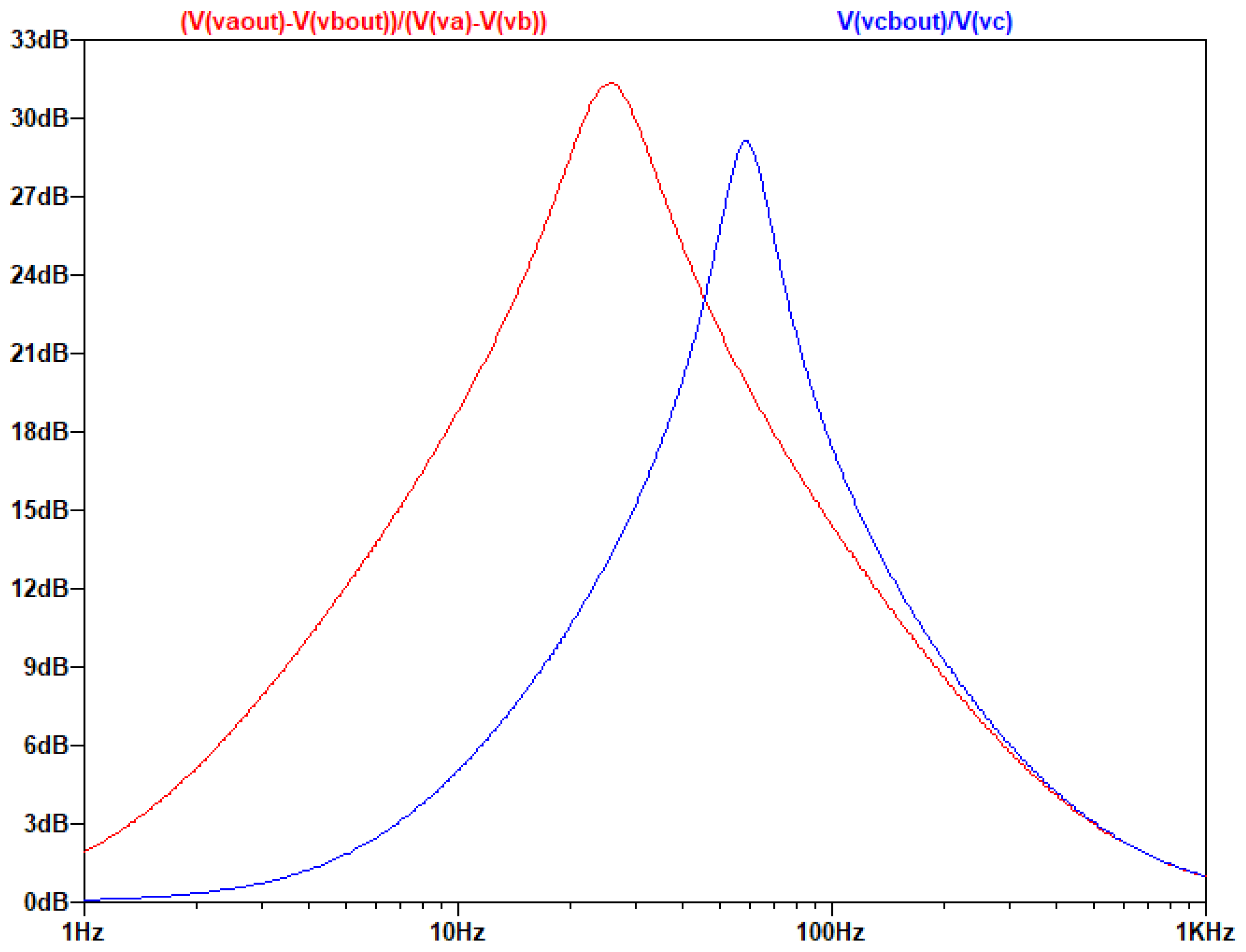
Figure 3.3.2.
Τhe gain of the common and differential signal as a function of frequency.
It is noticed that the differential signal is amplified as expected from the chosen values of the resistors and the circuit presents a form like a low-pass filter, while for the common signal the circuit presents the form of a high-Q filter with no general amplification.
Proof of Equivalence with the Simplified Circuits for Differential and Common Signal
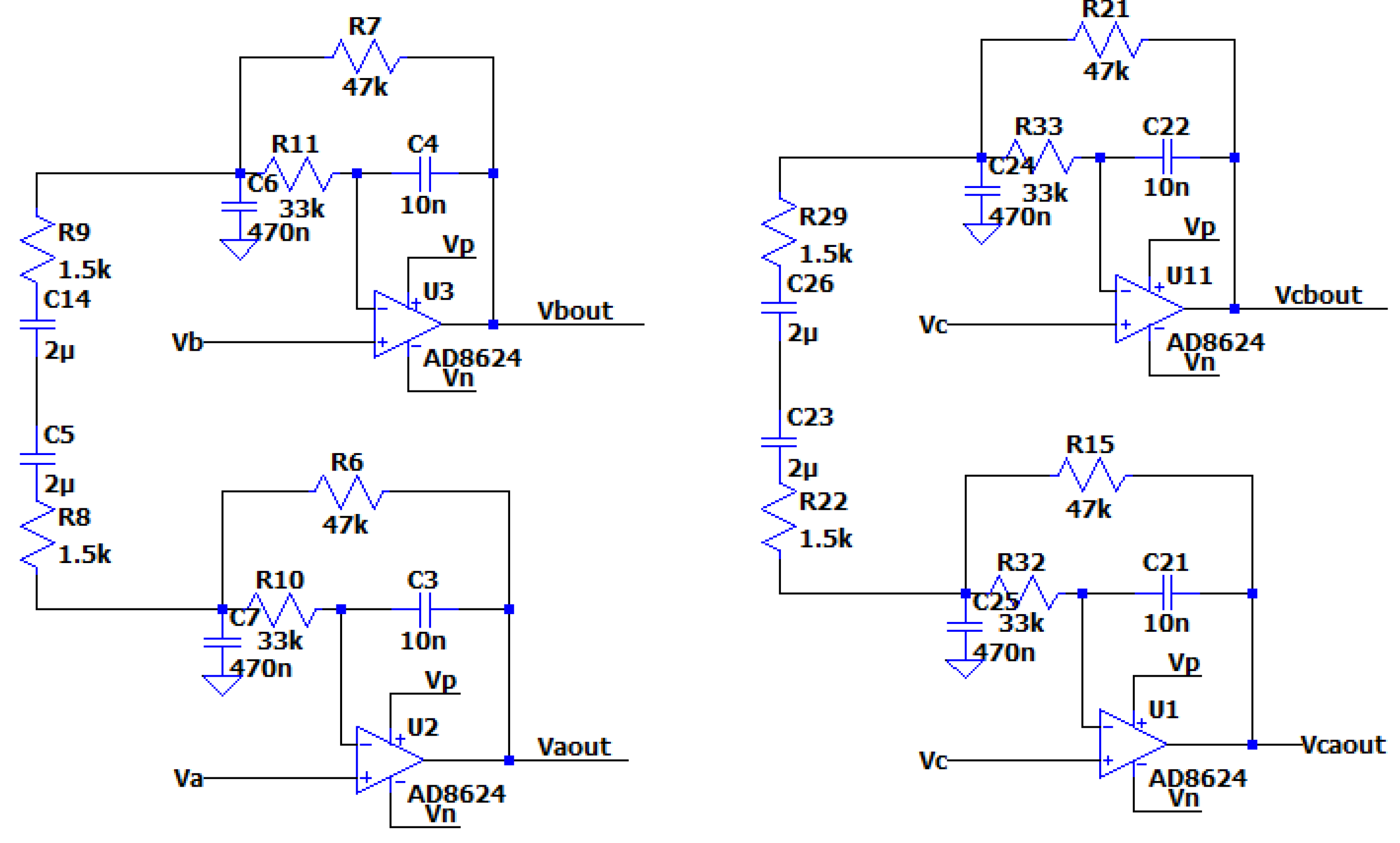
The AC Analysis of the simplified circuits for differential and common signal was performed using the following SPICE model:
Figure 3.3.3.
The simplified circuits of the MFDFIA for the differential signal and the common signal.
Figure 3.3.3.
The simplified circuits of the MFDFIA for the differential signal and the common signal.
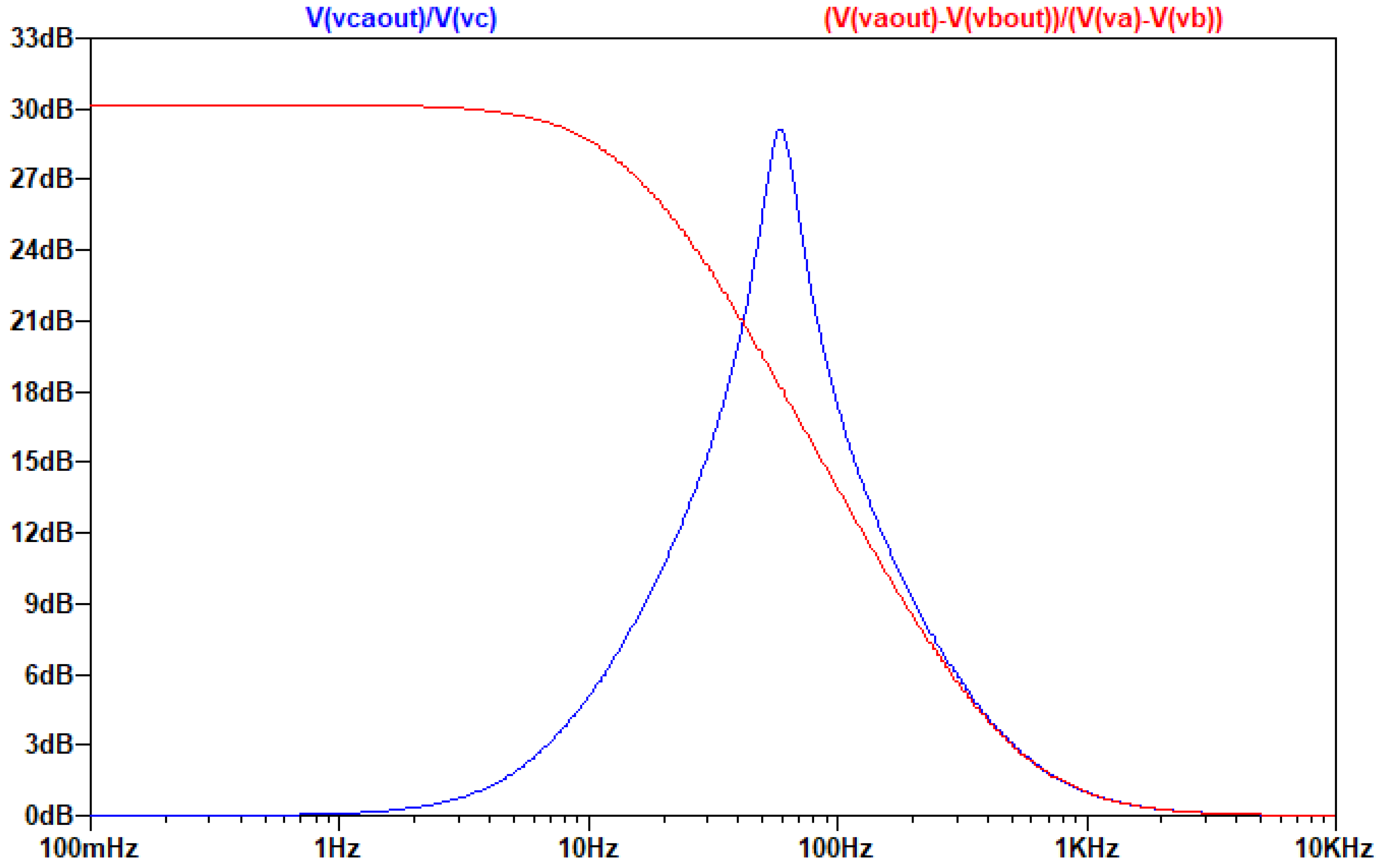
The output of the AC analysis is seen in the following figure:
Figure 3.3.4.
Τhe gain of the simplified circuits for the common and the differential signal as a function of frequency.
Figure 3.3.4.
Τhe gain of the simplified circuits for the common and the differential signal as a function of frequency.
It is noticed that the results of the AC analysis for the gain of the differential and the common signal in Figure 3.3.2 are the same with the results in Figure 3.3.4.
Example of a Band-Pass Differential Filter
By replacing the resistor Z with RC, a band-pass differential filter is created, as the capacitors cut the DC current and create a zero solution in the nominator of the fraction in the transfer function. So, the circuit will act like a band pass filter. The transfer function becomes a third order polynomial making difficult to specify the contribution of the existence of this zero in the filters behavior. However, it will be near 1/RC. The AC Analysis of the filter was performed using the following circuit:
Figure 3.3.5.
The circuit of the Band-Pass Differential Filter with Va, Vb, simulating the differential signal and Vc simulating the common signal.
Figure 3.3.5.
The circuit of the Band-Pass Differential Filter with Va, Vb, simulating the differential signal and Vc simulating the common signal.
The output of the AC analysis is seen in the following figure:
Figure 3. 3.6.
Τhe gain of the common and differential signal as a function of frequency.
One of the most noteworthy elements of this design is that the common and the differential input can be amplified in different frequency ranges.
It is also observed that the Z resistor affects only the differential signal and not the common signal which makes the differential amplifier useful in a variety of application in a diverse number of fields, i.e. biomedicine, geophysics, telecommunications, defense, etc.. Thus, the proposed approach allows the design of complex circuits (filters of higher degree) affecting only the differential signal.
Elimination of the Common Signal Gain
From the simplified analysis of the differential input signal, the “point” between the Z resistors in the circuit has zero voltage. This “point” is a “virtual ground”. If the branches which were connected to the real ground, are connected to the “virtual ground”, the current that flows through these branches will be zero, only in the case of common input signal. So the circuit for the common signal is essentially a buffer and the gain of the circuit of the common signal is eliminated. However, the circuit for the differential signal normally “sees” the filter as if it had the branches connected to the real ground. This fact is clear from the simplified analysis.
The AC Analysis of the filter was performed using the following circuit:
Figure 3.3.7.
The circuit with Va, Vb, simulating the differential signal and Vc simulating the common signal.
Figure 3.3.7.
The circuit with Va, Vb, simulating the differential signal and Vc simulating the common signal.
The output of the AC analysis is seen in the following figure:
Figure 3 3.8.
Τhe gain of the common and differential signal as a function of frequency.
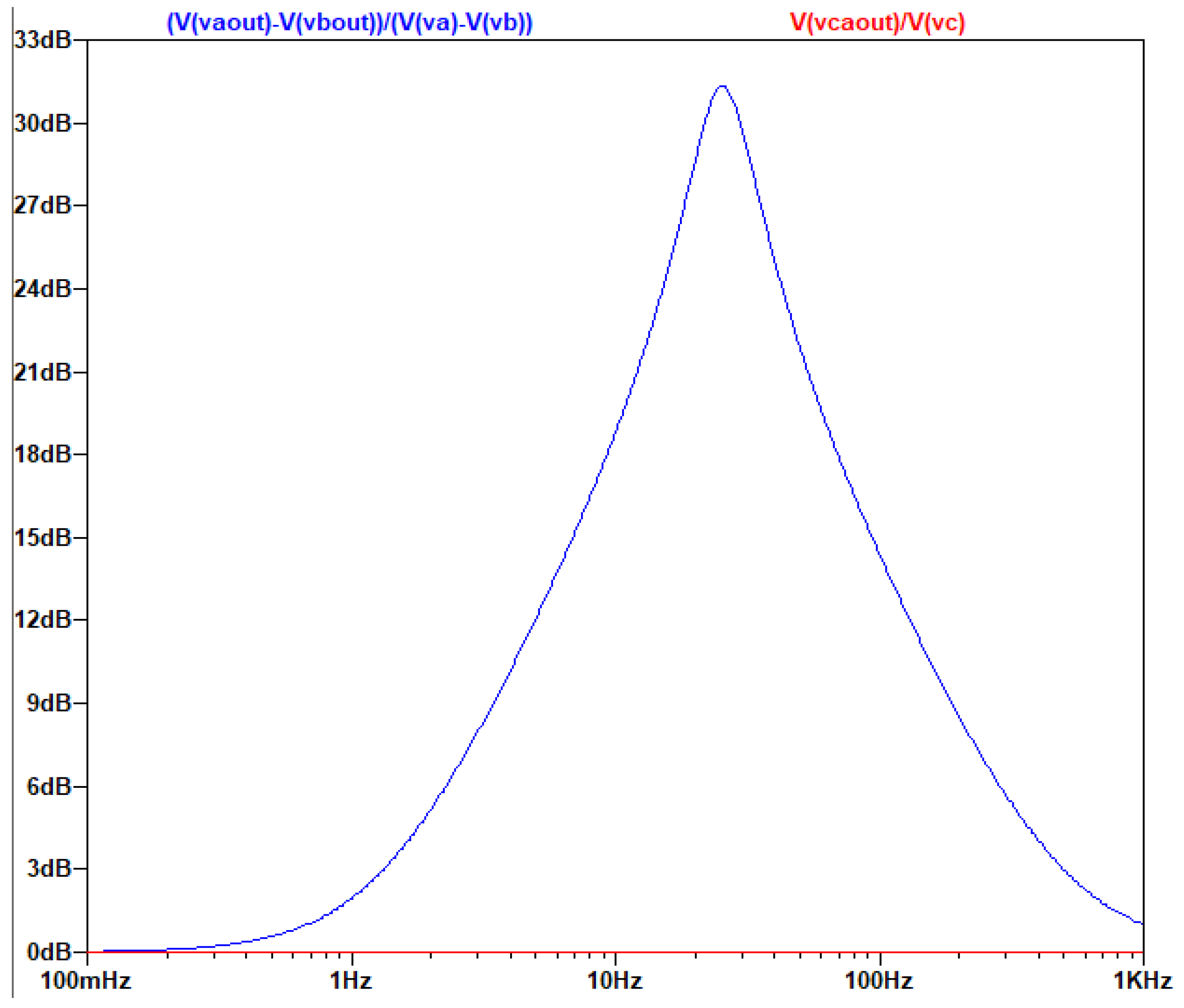
As is seen in the AC analysis, by connecting the capacitors in the middle of the Z branch, on the one hand the common-mode signal is indeed eliminated, on the other hand the differential signal’s amplification is not affected and the topology still produces a ~31db gain to it.
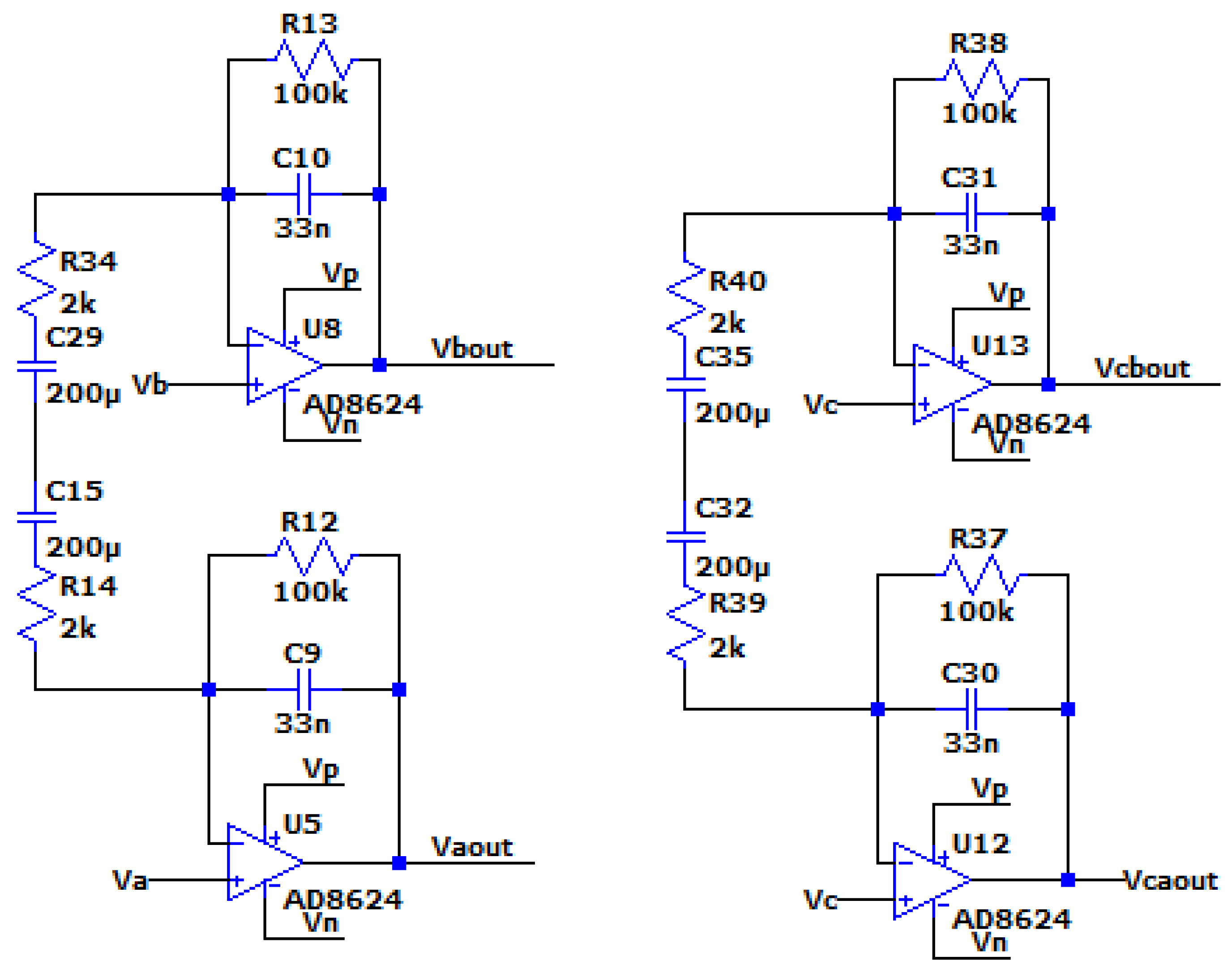
3.4. Design Optimization of the Multi-Feedback Differential Filter in the Case of EEG
In the case of EEG, our goal is to amplify the differential input signal between 1-30 Hz without amplifying the common signal. Since our filter has to be broadband, we do not need a high Q filter. In order to achieve this, we remove the capacitors attached to ground. By removing the capacitors, the filter acts like a 1st order low pass filter, with a pole created from the feedback resistor and the feedback capacitor.
In order to achieve a bandpass filter, we replace Z with a series RC, which produces a zero near 1Hz. With these modifications we can design a bandpass filter with slope of almost 20 db/decade, which is equal to the slope of the previously analyzed filter in the case of low Q.
We notice again that the unity constant in the transfer function limits the gain of the filter to 0dB and not lower than this, so in high frequencies the transfer function is dominated by the unit. Because of these alterations, the resistor at the negative input of the operation amplifier is not necessary. This derived improved model version can be seen in the next figure.
Figure 3.4.1.
The circuit of the optimized filter for EEG.
The AC Analysis of the filter was performed using the following SPICE model:
Figure 3.4.2.
The circuit of the optimized MFDFIA with Va, Vb, simulating the differential signal and Vc simulating the common signal.
Figure 3.4.2.
The circuit of the optimized MFDFIA with Va, Vb, simulating the differential signal and Vc simulating the common signal.
The output of the AC analysis is seen in the following figure:
Figure 3.4.3.
Τhe graphical representation of the gain of the common and differential signal as a function of frequency.
Figure 3.4.3.
Τhe graphical representation of the gain of the common and differential signal as a function of frequency.
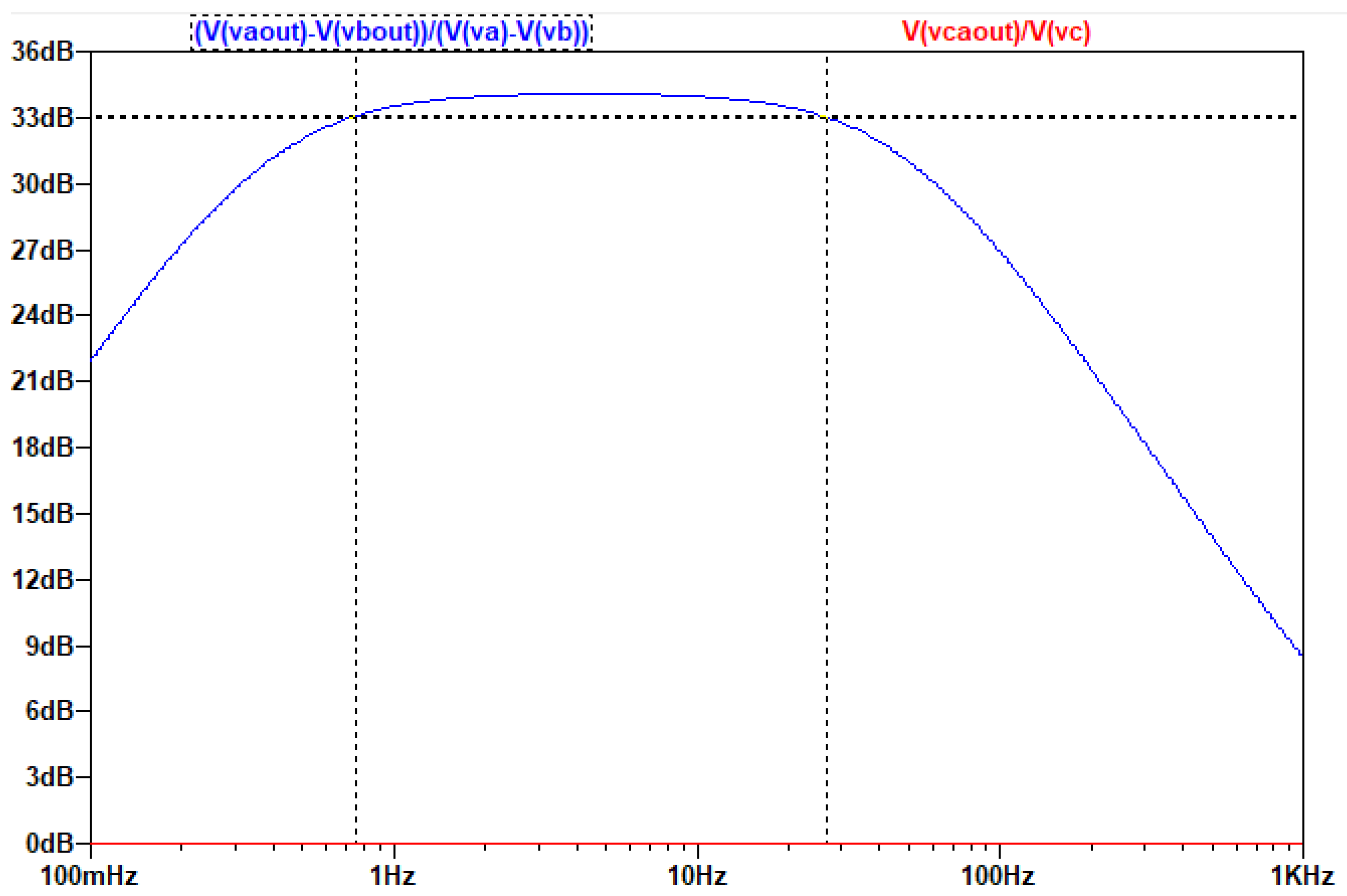
Due to the unit in the transfer function of the circuit, which does not allow the drop of the filter’s gain at high frequencies below 0db, it is necessary to add a low pass filter (at least first degree) before placing the A/D converter, as it is seen in the following figure:
Figure 3.4.4.
The circuit of the optimized MFDFIA, including a low pass filter, with Va, Vb, simulating the differential signal and Vc simulating the common signal.
Figure 3.4.4.
The circuit of the optimized MFDFIA, including a low pass filter, with Va, Vb, simulating the differential signal and Vc simulating the common signal.
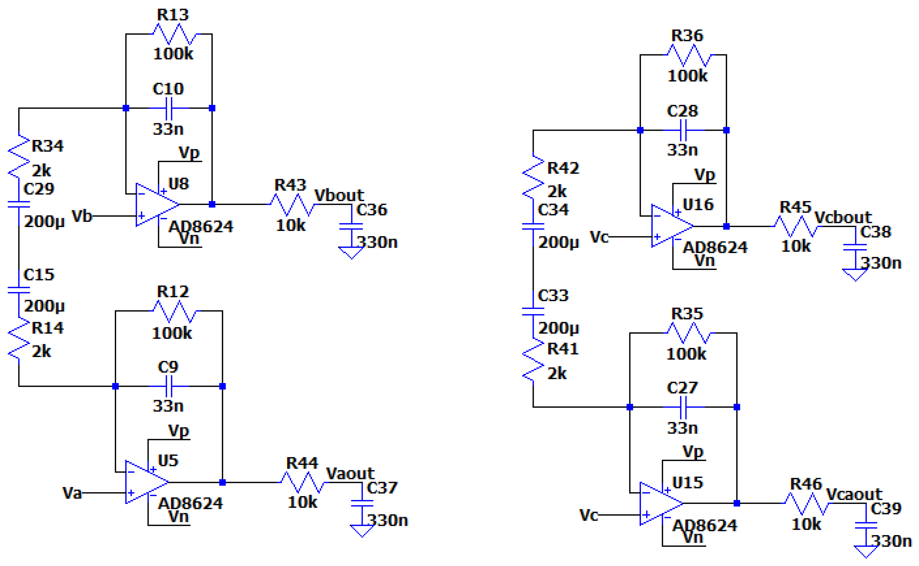
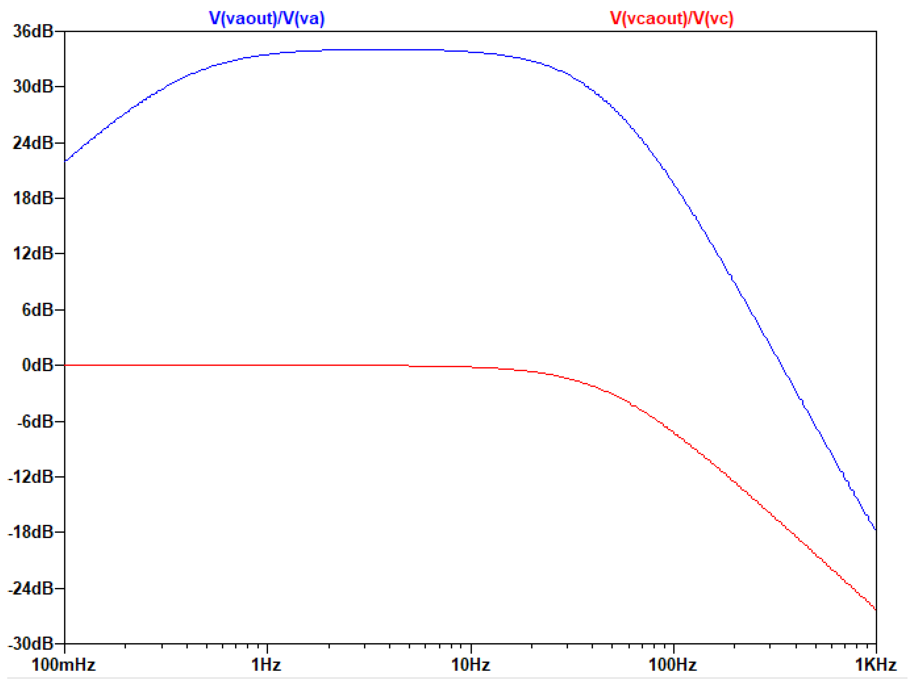
The output of the AC analysis is seen in the following figure:
Figure 3.4.5.
Τhe graphical representation of the gain of the common and differential signal as a function of frequency.
Figure 3.4.5.
Τhe graphical representation of the gain of the common and differential signal as a function of frequency.
4. Discussion
The designed novel MFDFIA constitutes an effective solution of the problems stated in the introduction of this work, which are especially true in biosignal acquisition, where maintaining signal integrity is crucial (pre- and post- amplification filtering problems). As shown in section 3 of this work, this novel circuit design can mitigate the aforementioned problems.
By integrating a multi-feedback filter directly into the instrumentation amplifier, the MFDFIA circuit enables simultaneous amplification and filtering of biosignals. A significant advantage of the MFDFIA is its high input impedance, achieved by utilizing the positive input of the amplifiers as the signal input which diminishes issues associated with electrode-skin impedance variability, as the filtering characteristics are practically independent of the source impedance.
This results in an input resistance that is orders of magnitude greater than the resistance of the electrodes, ensuring minimal loading effect on the signal source and preserving the integrity of the biosignals. This characteristic makes it compatible with both wet and dry electrodes which is particularly beneficial in applications like EEG, where electrode-skin impedance is usually unknown.
The symmetric topology simplifies analysis by allowing separate examination of differential and common-mode signals using as the equivalent electronic model only a single-op-amp circuit. By simplifying the model, it is obvious that many complex filters can be created. As a general rule, any branch connected to ground will increase the gain of the common signal.
The use of virtual ground leads to the decoupling of the filter operation in terms of the common and differential signal. This results in the common signal being neither amplified nor filtered, in which case the circuit acts as a buffer. In the case of the differential component of the signal the circuit works normally as a filter.
Using as second stage a differential ADC 24-bit, the MFDFIA can exhibit a high CMRR that depends solely on the second stage of the amplifier. Since the first stage (MFDFIA) behaves as a buffer with respect to the common mode signal, the CMMR is practically dependent on preserving the symmetry of the components, which is a function of their quality and particularly tolerance levels of the components used. This enhances its ability to suppress unwanted common-mode signals such as mains interference and artifacts prevalent in biosignal measurements. The satisfactory noise performance, depending on the components choice of the engineer, can results in a high signal-to-noise ratio (SNR), essential for accurate detection and acquisition of low-amplitude biosignals, meeting the stringent requirements of EEG systems and other bio-amplifier circuits.
On the other hand, a feature of the MFDFIA is its dual-bandwidth capability, as shown in Section 3.3 and 3.4, allowing it to amplify and filter signals within two distinct bandwidth ranges. This flexibility enables the amplifier to function as both a broadband amplifier and a low-pass filter, depending on application requirements. Such adaptability extends its utility to other applications. As an example, in telecommunications the engineers could use the common mode signal to transmit the clock and the differential signal to transmit the information and the MFDFIA can be used to decouple the clock from the information on the receiver’s side.
5. Conclusions
To recapitulate, the novel MFDFIA effectively overcomes the limitations of traditional biosignal acquisition circuits by integrating filtering and amplification into a single stage. This design addresses challenges posed by variable electrode impedance and efficiently suppresses common-mode interference, enhancing the quality of acquired biosignals. Compared to existing designs, the MFDFIA offers a comprehensive solution by combining amplification and filtering in a single stage, reducing component count and system complexity. Its robust performance in gain, bandwidth, noise, and power consumption positions it as a valuable component in biosignal acquisition systems, such as the EEG, and other applications requiring reliable and high-quality signal amplification and filtering, such as applications requiring sensitive sensing.
Simulation results confirm that the amplifier achieves the necessary bandwidth and gain for EEG applications while maintaining low power consumption and low noise levels. Overall, the MFDFIA offers a robust and versatile solution for improving signal integrity in biosignal acquisition systems.
Author Contributions
Conceptualization, A.D.; methodology, A.D., D.P.G. and K.P.; software, A.D., D.P.G. and K.P.; validation, A.D., D.P.G., I.S., E.A. and K.P.; formal analysis, A.D. and D.P.G.; investigation, A.D., D.P.G., I.S. and E.A.; resources, A.D., E.A. and K.P.; data curation, A.D., D.P.G. and I.S.; writing—original draft preparation, A.D., D.P.G. and I.S.; writing—review and editing, A.D., D.P.G., I.S., E.A. and K.P.; visualization, A.D. and D.P.G.; supervision, E.A. and K.P.; project administration, A.D. All authors have read and agreed to the published version of the manuscript.
Funding
This research received no external funding.
Data Availability Statement
The original contributions presented in the study are included in the article.
Acknowledgments
Despoina-Polyxeni Georgiou and Ioannis Stamelos would like to thank the Biomedical Engineering student group "MedHub Athens" from the School of Medicine, National and Kapodistrian University of Athens, of which they are members, for inspiring and supporting their participation in this work.
Conflicts of Interest
The authors declare no conflicts of interest.
Appendix A
Kirchhoff current laws (KCL) for circuit in Figure 3.1.1 are:
Kirchhoff voltage laws (KVL) for circuit in Figure 3.1.1 are:
Kirchhoff current laws (KCL) for circuit in Figure 3.1.1 are:
Ohm’s Laws in Figure 3.1.1 are:
From equations (A.4) and (A.5) it can be derived that:
From equations (A.6) and (A.7) it can be derived that:
From equations (A.8) and (A.9) it can be derived that:
From equations (A.10) and (A.11) it can be derived that:
From equations (A.1) and (A.2) it can be derived that:
From equations (A.3), (A.12), (A.14), (A.15) and (A.16) it can be derived that:
From equations (A.17) and (A.13) it can be derived that:
Appendix B
Kirchhoff current laws (KCL) for circuit in Figure 3.2.2 are:
Ohm’s laws for circuit in Figure 3.2.2 are:
From equations (C.2) and (C.3) it can be derived that:
From equations (C.1),(C.3),(C.4),(C.5),(C.6):it can be derived that:
From equations (C.7),(C.8) it can be derived that:
Appendix C
Kirchhoff current laws (KCL) for circuit in Figure 3.2.1 are:
Ohm’s laws for circuit in Figure 3.2.1 are:
From equations (B.2),(B.3) it can be derived that:
From equations (B.1),(B.3),(B.4),(B.5) it can be derived that:
From equations (B.6),(B.7) it can be derived that:
References
- Michel, C.M.; Brunet, D. EEG Source Imaging: A Practical Review of the Analysis Steps. Front. Neurol. 2019, 10, 325. [Google Scholar] [CrossRef]
- Beniczky, S.; Schomer, D.L. Electroencephalography: Basic Biophysical and Technological Aspects Important for Clinical Applications. Epileptic Disord. 2020, 22, 697–715. [Google Scholar] [CrossRef]
- Seeber, M.; Cantonas, L.-M.; Hoevels, M.; Sesia, T.; Visser-Vandewalle, V.; Michel, C.M. Subcortical Electrophysiological Activity Is Detectable with High-Density EEG Source Imaging. Nat. Commun. 2019, 10, 753. [Google Scholar] [CrossRef]
- Parvizi, J.; Kastner, S. Promises and Limitations of Human Intracranial Electroencephalography. Nat. Neurosci. 2018, 21, 474–483. [Google Scholar] [CrossRef]
- Noachtar, S.; Rémi, J. The Role of EEG in Epilepsy: A Critical Review. Epilepsy Behav. 2009, 15, 22–33. [Google Scholar] [CrossRef]
- Yang, W.; Wang, X.; Liu, H.; Li, M.; Liu, X.; Lin, N.; Hu, L.; Han, R. Electroencephalography Characteristics of Patients with Supratentorial Glioma in Different Consciousness States Induced by Propofol. Neurosci. Lett. 2023, 808, 137284. [Google Scholar] [CrossRef]
- Valdés, R.F.R. Value of the Electroencephalogram in Viral Encephalitis. JPNC 2018, 8. [Google Scholar] [CrossRef]
- Rundo, J.V.; Downey, R. Polysomnography. In Handbook of Clinical Neurology; Elsevier, 2019; Vol. 160, pp. 381–392 ISBN 978-0-444-64032-1.
- Sturzbecher, M.J.; De Araujo, D.B. Simultaneous EEG-fMRI: Integrating Spatial and Temporal Resolution. In The Relevance of the Time Domain to Neural Network Models; Rao, A.R., Cecchi, G.A., Eds.; Springer US: Boston, MA, 2012; pp. 199–217. ISBN 978-1-4614-0723-2. [Google Scholar]
- Värbu, K.; Muhammad, N.; Muhammad, Y. Past, Present, and Future of EEG-Based BCI Applications. Sensors 2022, 22, 3331. [Google Scholar] [CrossRef]
- Islam, M.K.; Rastegarnia, A.; Yang, Z. Methods for Artifact Detection and Removal from Scalp EEG: A Review. Neurophysiol. Clin. /Clin. Neurophysiol. 2016, 46, 287–305. [Google Scholar] [CrossRef] [PubMed]
- Xie, Y.; Oniga, S. A Review of Processing Methods and Classification Algorithm for EEG Signal. Carpathian J. Electron. Comput. Eng. 2020, 13, 23–29. [Google Scholar] [CrossRef]
- Vanhatalo, S.; Voipio, J.; Kaila, K. Full-Band EEG (FbEEG): An Emerging Standard in Electroencephalography. Clin. Neurophysiol. 2005, 116, 1–8. [Google Scholar] [CrossRef] [PubMed]
- Vanhatalo, S.; Tallgren, P.; Andersson, S.; Sainio, K.; Voipio, J.; Kaila, K. DC-EEG Discloses Prominent, Very Slow Activity Patterns during Sleep in Preterm Infants. Clin. Neurophysiol. 2002, 113, 1822–1825. [Google Scholar] [CrossRef]
- Hinterberger, T.; Schmidt, S.; Kamei, T.; Walach, H. Decreased Electrophysiological Activity Represents the Conscious State of Emptiness in Meditation. Front. Psychol. 2014, 5. [Google Scholar] [CrossRef]
- Hosang, L.; Mouchlianitis, E.; Guérin, S.M.R.; Karageorghis, C.I. Effects of Exercise on Electroencephalography-Recorded Neural Oscillations: A Systematic Review. Int. Rev. Sport. Exerc. Psychol. 2022, 1–54. [Google Scholar] [CrossRef]
- McCormick, D.A.; McGinley, M.J.; Salkoff, D.B. Brain State Dependent Activity in the Cortex and Thalamus. Curr. Opin. Neurobiol. 2015, 31, 133–140. [Google Scholar] [CrossRef]
- Buzsáki, G.; Silva, F.L.D. High Frequency Oscillations in the Intact Brain. Prog. Neurobiol. 2012, 98, 241–249. [Google Scholar] [CrossRef]
- Alkhorshid, D.R.; Molaeezadeh, S.F.; Alkhorshid, M.R. Analysis : Electroencephalography Acquisition System: Analog Design. Biomed. Instrum. Technol. 2020, 54, 346–351. [Google Scholar] [CrossRef]
- Kuo, K.-C.; Chen, C.-T.; Liao, H.-Y. An Area Efficient Analog Front-End for Sensing EEG Signals with MOS Capacitors in 90nm Process. In Proceedings of the 2023 International Conference on Consumer Electronics - Taiwan (ICCE-Taiwan); IEEE: PingTung, Taiwan, July 17 2023; pp. 255–256. [Google Scholar]
- Cornelio, Z.U.; Resurreccion, P.; Leon, M.T.D.; Rosales, M.; Hizon, J.R. An EEG Analog Front-End Unit for Wearable Applications Implemented in 28nm FD-SOI. In Proceedings of the 2023 20th International SoC Design Conference (ISOCC); IEEE: Jeju, Korea, Republic of, October 25 2023; pp. 15–16. [Google Scholar]
- Le, D.H.; Pham, T.-H.; Pham, C.-K. Design of a Configurable 4-Channel Analog Front-End for EEG Signal Acquisition on 180nm CMOS Process. REV J. Electron. Commun. 2023. [Google Scholar] [CrossRef]
- Pham, T.-H.; Huynh, H.-A.; Pham, C.-K.; Le, D.-H. Design of a Configurable Low-Noise 1-Channel Analog Front-End for EEG Signal Recording on 180nm CMOS Process. In Proceedings of the 2023 International Conference on Advanced Technologies for Communications (ATC); IEEE: Da Nang, Vietnam, October 19 2023; pp. 61–66. [Google Scholar]
- Li, X.; Ren, S.; Li, X.; Zhao, T.; Deng, X.; Zheng, W. A LFP/AP Mode Reconfigurable Analog Front-End Combining an Electrical EEEG-iEEG Model for the Closed-Loop VNS. IEEE Trans. Biomed. Circuits Syst. 2024, 18, 408–422. [Google Scholar] [CrossRef] [PubMed]
- Hu, H.-Y.; Wang, L.-H.; Kuo, I.-C.; Wang, M.-H.; Wang, S.-F.; Huang, P.-C. A Multi-Channel EEG Acquisition Device Based on BT Microcontroller. In Proceedings of the 2023 International Conference on Consumer Electronics - Taiwan (ICCE-Taiwan); IEEE: PingTung, Taiwan, July 17 2023; pp. 251–252. [Google Scholar]
- Han, Y.; Zhao, L.; Stephany, R.G.; Hsieh, J.-C.; Wang, H.; Jia, Y. A Scattered Wireless EEG Recording System. In Proceedings of the 2023 IEEE Biomedical Circuits and Systems Conference (BioCAS); IEEE: Toronto, ON, Canada, October 19 2023; p. 5. [Google Scholar]
- Chen, W. Multi-Channel EEG Signal Acquisition System Based on nRF52832. In Proceedings of the 2023 5th International Conference on Communications, Information System and Computer Engineering (CISCE); IEEE: Guangzhou; IEEE: Guangzhou, China, April 14 2023; pp. 80–83. [Google Scholar]
- Liu, L.; Xu, J.; Yin, J.; Liao, X.; Tian, Y. A Low-Power and Constant-Bandwidth Analog Front End Based on Current-Reused DDA for Multibiosignal Acquisition. IEEE Sens. J. 2023, 23, 24711–24720. [Google Scholar] [CrossRef]
- Ge, T.; Li, P.; Duan, Q.; Yu, G. A Low-Noise, High-Precision Chopper Instrument Amplifier for EEG Signal Amplification. In Proceedings of the 2023 5th International Conference on Circuits and Systems (ICCS); IEEE: Huzhou, China, October 27 2023; pp. 75–80. [Google Scholar]
- Tsuji Tinem, Gabriel. Ultra-low-power instrumentation amplifiers with cuff electrodes for detection of epileptic seizures. Ecole polytechnique de Louvain, Université catholique de Louvain, 2020. Prom. : Bol, David. http://hdl.handle.net/2078.1/thesis:26570.
- Mii, K.; Kanemoto, D.; Hirose, T. 0.36 μW/Channel Capacitively-Coupled Chopper Instrumentation Amplifier in EEG Recording Wearable Devices for Compressed Sensing Framework. Jpn. J. Appl. Phys. 2024, 63, 03SP54. [Google Scholar] [CrossRef]
- Gajare, M.; D.K., S. CMOS Trans Conductance Based Instrumentation Amplifier for Various Biomedical Signal Analysis. NQ 2022, 20, 53–60. [Google Scholar] [CrossRef]
- Balaramudu, K.; Sharma, D.P. DESIGN OF INSTRUMENTATION AMPLIFIER OF CMOS CIRCUIT 45nm TECHNOLOGHY FOR DETECTION OF ECG SIGNAL. NeuroQuantology 2022, 20, 1505–1510. [Google Scholar] [CrossRef]
- Chebli, R.; Ali, M.; Sawan, M. High-CMRR Low-Noise Fully Integrated Front-End for EEG Acquisition Systems. Electronics 2019, 8, 1157. [Google Scholar] [CrossRef]
- Ahmad, R.; Choudhary, N.; Gupta, S.K.; Joshi, A.M.; Boolchandani, D. Novel Tunable Current Feedback Instrumentation Amplifier Based on BBFC OP-AMP for Biomedical Applications with Low Power and High CMRR. Integration 2023, 90, 214–223. [Google Scholar] [CrossRef]
- Ahmad, R.; Choudhary, N.; Gupta, S.K.; Joshi, A.M.; Boolchandani, D. Novel Tunable Current Feedback Instrumentation Amplifier Based on BBFC OP-AMP for Biomedical Applications with Low Power and High CMRR. Integration 2023, 90, 214–223. [Google Scholar] [CrossRef]
- J, J.J.; J, J.J.; Bharathi, R.J.; E, A.; N, A.S. Low Cost Analog EEG Amplifier for Healthcare Applications. In Proceedings of the 2022 6th International Conference on Electronics, Communication and Aerospace Technology; IEEE: Coimbatore, India, December 1 2022; pp. 375–379. [Google Scholar]
- Armano, M.; Audley, H.; Baird, J.; Benella, S.; Binetruy, P.; Born, M.; Bortoluzzi, D.; Castelli, E.; Cavalleri, A.; Cesarini, A.; et al. Forbush Decreases and <2 Day GCR Flux Non-Recurrent Variations Studied with LISA Pathfinder. ApJ 2019, 874, 167. [Google Scholar] [CrossRef]
- Ren, Q.; Chen, C.; Dong, D.; Xu, X.; Chen, Y.; Zhang, F. A 13 µW Analog Front-End with RRAM-Based Lowpass FIR Filter for EEG Signal Detection. Sensors 2022, 22, 6096. [Google Scholar] [CrossRef]
- Dabbaghian, A.; Kassiri, H. An 8-Channel Ambulatory EEG Recording IC With In-Channel Fully-Analog Real-Time Motion Artifact Extraction and Removal. IEEE Trans. Biomed. Circuits Syst. 2023, 17, 999–1009. [Google Scholar] [CrossRef]
- Teki̇N, K.; Güler, H. Second Generation Current Controlled Current Conveyor Based Low Pass Filter Design For The Processing of EEG Signals. Turk. J. Sci. Technol. 2023, 18, 405–413. [Google Scholar] [CrossRef]
- Qian, Y.-Y.; Wang, Z.-G.; Liu, Y.-K.; Zhou, Z.-J. A High Gain and High CMRR Instrumentation Amplifier for Biomedical Applications. In Proceedings of the 2019 IEEE 4th International Conference on Integrated Circuits and Microsystems (ICICM); IEEE: Beijing, China, October, 2019; pp. 61–64. [Google Scholar]
- Lee, C.-J.; Song, J.-I. A Chopper-Stabilized Amplifier With a Tunable Bandwidth for EEG Acquisition Applications. IEEE Access 2019, 7, 73165–73171. [Google Scholar] [CrossRef]
- Huang, C.-W.; Wang, J.-J.; Hung, C.-C.; Wu, C.-Y. Design of CMOS Analog Front-End Electroencephalography (EEG) Amplifier with ±1-V Common-Mode and ±10-mV Differential-Mode Artifact Removal. In Proceedings of the 2022 IEEE Biomedical Circuits and Systems Conference (BioCAS); IEEE: Taipei, Taiwan, October 13 2022; pp. 714–717. [Google Scholar]
- Girinath, N.; Visvesvaran, C.; Babu C., G. Current-Feedback Instrumentation Amplifier for Bio-Potential Signal Acquisition Applications. In Proceedings of the 2019 International Conference on Advances in Computing and Communication Engineering (ICACCE); IEEE: Sathyamangalam, India, April 2019; pp. 1–4. [Google Scholar]
- Yue-Der Lin; Chang-Da Tsai; Hui-Hsun Huang; Dah-Chuan Chiou; Chien-Ping Wu Preamplifier with a Second-Order High-Pass Filtering Characteristic. IEEE Trans. Biomed. Eng. 1999, 46, 609–612. [CrossRef] [PubMed]
- Harrison, R.R. A Versatile Integrated Circuit for the Acquisition of Biopotentials. In Proceedings of the 2007 IEEE Custom Integrated Circuits Conference; IEEE: San Jose, CA, September 2007; pp. 115–122. [Google Scholar]
- Blomqvist, K.H.; Eskelinen, P.; Sepponen, R.E. Instrumentation Amplifier Implements Second-Order Active Low-Pass Filter with High Gain Factor. Meas. Sci. Technol. 2011, 22, 057002. [Google Scholar] [CrossRef]
Disclaimer/Publisher’s Note: The statements, opinions and data contained in all publications are solely those of the individual author(s) and contributor(s) and not of MDPI and/or the editor(s). MDPI and/or the editor(s) disclaim responsibility for any injury to people or property resulting from any ideas, methods, instructions or products referred to in the content. |
© 2024 by the authors. Licensee MDPI, Basel, Switzerland. This article is an open access article distributed under the terms and conditions of the Creative Commons Attribution (CC BY) license (http://creativecommons.org/licenses/by/4.0/).
Copyright: This open access article is published under a Creative Commons CC BY 4.0 license, which permit the free download, distribution, and reuse, provided that the author and preprint are cited in any reuse.


