1. Introduction
In recent years, Hellenic Distribution Network Operator (HEDNO) has embarked on an ambitious project to overlay a fiber optic network on the existing infrastructure of the electrical distribution grid, specifically utilizing the existing poles. This innovative approach is reflective of trends observed among network operators throughout Europe, with notable examples in Italy and Romania, where similar strategies have been employed. The rationale behind this initiative revolves around leveraging existing infrastructure to facilitate the deployment of fiber optic technology, which is pivotal in modern telecommunications and data transmission.
Initially, the focus of this project was on the technical aspects of such an integration. These considerations included evaluating the proximity of the fiber optic cables to both low and medium voltage overhead conductors, determining optimal suspension points along cable routes, strategizing the placement relative to streetlights, ensuring sufficient clearance above ground and roadways, maintaining lateral distance from adjacent structures, and assessing the structural robustness of the poles used in the distribution grid.
However, as the project has evolved, the scope of investigation has broadened. The current phase emphasizes developing standardized procedures for securely mounting optical fibers, delineating the characteristics of the support structures needed, ensuring the safety of personnel involved in the installation process, and addressing concerns related to electromagnetic compatibility. This phase particularly focuses on two critical scenarios: (a) the attachment of fiber optic cables to HEDNO's supply cable, and (b) the securement of these cables to the structural elements of overhead medium voltage/low voltage substations, with an emphasis on maintaining uninterrupted power supply during the installation process.
While Greek legislation, the Greek Standardization Organization (ELOT) standards, and HEDNO's Standardized Distribution Structures provide guidelines covering several of these technical aspects, there remains a notable gap. This gap lies in the alignment of these local regulations with broader European (EN) standards and international guidelines, such as those set forth by the IEEE. This misalignment presents challenges in standardizing and universally applying the deployment of an overhead fiber optic network in the scenarios. This paper aims to address these challenges, proposing solutions to harmonize local practices with international standards, thereby facilitating a smoother and more efficient implementation of this critical infrastructure upgrade.
2. Survey of International Literature
This section includes key findings from international resources on the separation of IT and power supply cabling. Surveying on research studies, IEEE and European standards, the following are taken into account:
ELOT EN 50174.03 [
1] emphasizes minimizing interaction between aerial IT cabling and low voltage power supply cables, prescribing specific installation practices to ensure safety and efficiency. It recommends IT cables be positioned below power cables with a minimum separation distance that varies depending on insulation standards.
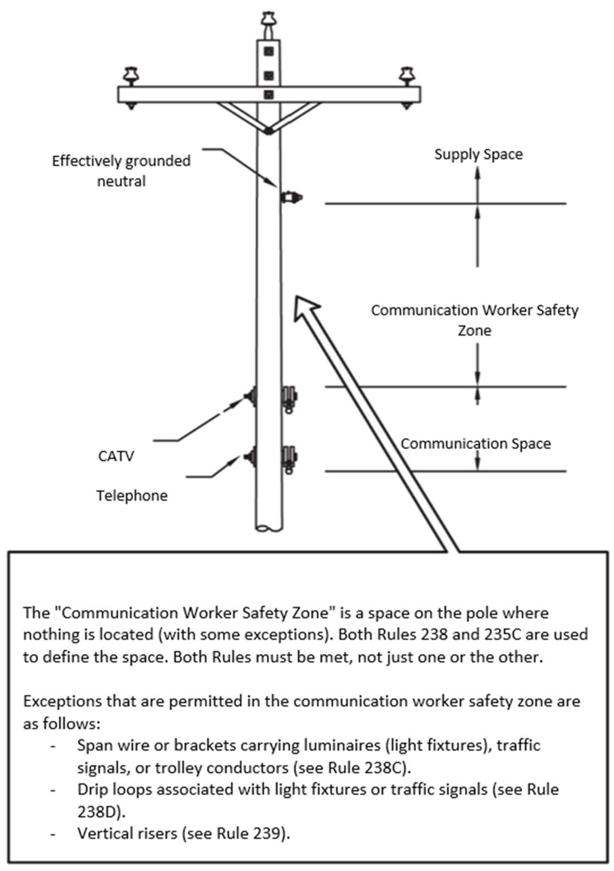
IEEE-2023 National Electrical Safety Code [
2,
3,
4] outlines rules for the separation of IT and power cables across various voltage levels, including guidelines for the installation to enhance durability and safety. It specifies minimum vertical and lateral separation distances, particularly emphasizing a safety zone for communication workers (
Figure 1).
Regulation on the Installation and Maintenance of Outdoor Power Lines [
5] sets the minimum vertical distance requirements between power and telecommunication cables, with specific distances for low and medium voltage scenarios to ensure safety and operational efficiency.
Directive No15 of HEDNO [
6] and HEDNO Standardized Distribution Network Structures [
7] provide guidelines on working near under-voltage installations and the necessary precautions to prevent accidental contact, without specifying distance requirements for power and telecom cables.
EN 50110.01 E3 [
8] deals with operation safety around electrical installations, specifying work zone distances for various voltage levels to ensure worker safety.
Analysis on Overhead Fiber Optic Network Installation Conditions [
9] explores safe distances for fiber optic cables in relation to electrical conductors, addressing electromagnetic compatibility and mechanical strength considerations.
Fiber Optics on Common Poles with MV Lines [
10,
11] investigates safety limits for electromagnetic exposure from medium voltage lines to optical fiber, concluding a 2-meter distance suffices under normal conditions but advising caution during adverse weather.
Table 1 provides a comparative summary of the installation and safety standards for fiber optic cables near medium voltage lines, as outlined by various regulatory bodies. It includes the minimum vertical distance requirements from overhead conductors, references to diagonal distances where applicable, and defined safe working zones for telecommunications personnel in relation to medium voltage lines. Specifically, the table highlights differences and similarities between standards such as ELOT EN 50174.03, IEEE NESC-2023, and specific Greek and international regulations, emphasizing the necessity of adhering to these guidelines to ensure safety and compliance.
3. Reasoned and documented optimum proposal for fibre installation
The main problems encountered in the joint installation of power cables and ADSS fibre optic cables are caused by the exposure of the fibre optic cable to the electromagnetic field of the conductors [
12], [
13]:
Corona effect and capacitive currents, where the transverse conductivity Y=G-jωC plays an important role, microsparking, where the transverse conductivity Y=G-jωC and the longitudinal resistance - equal and reciprocal Z=R+jωL and Z=Rm+jωM, and dry ribbon arcing, where the longitudinal resistance is important - equal and reciprocal Z=R+jωL and Z=Rm+jωM.
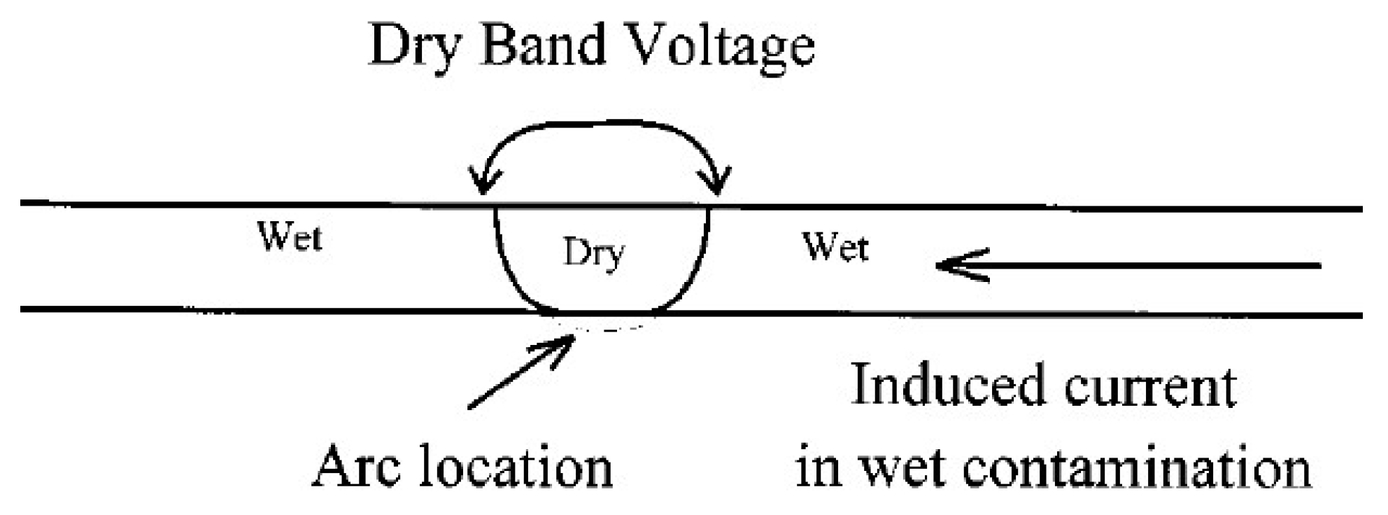
The outer sheath of insulated fibre optic cables, although hydrophobic and non-conductive, becomes hydrophilic and locally conductive over time (as shown in
Figure 2 below). As a result, it is subjected to currents induced by the overlying conductors (whether bare or insulated) and a potential difference is created at the dry points, which can generate electric arcs capable of causing damage to the fiber optic cladding.
To determine the induced voltages and currents within the optical fiber sheath, and thus establish the requisite safety margins between power conductors and the optical fiber, it is imperative to compute the electrical parameters of the conductor-fiber system. This involves calculating both the self-impedances and mutual resistances per unit length (denoted as Z), as well as the self and mutual transverse impedances per unit length (represented as Y). References [16-20] provide the foundational framework for these calculations.
4. Proposed Arrangement for Separation of IT Overhead Cabling and Power Supply Cables in low Voltage (400/230V)
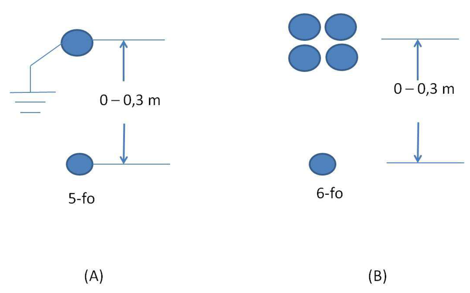
The research methodology employed by the team is predicated on an analysis of the fluctuation in electrical parameters—namely, impedances Z and transverse impedances Y—across all possible vertical separations from the optical fiber to the power cable, within the specified 0.0 to 0.3-meter range. This study particularly considers the scenario where the power cable is unshielded, interpreting it as an assembly of four insulated conductors, given that a shielded cable's grounded sheath significantly reduces electromagnetic interaction with the optical fiber, rendering the effect negligible. Consequently, parameter calculations were exclusively performed for the unshielded configuration as depicted in
Figure 3B. The electrical resistivity of the conductive elements was assumed to be equivalent to that of copper, at 1.7 x 10^-8 Ωm. In contrast, for the optical fiber's sheath, a spectrum of resistivity values was evaluated as documented in the literature [12-15], ranging from 10^-7 Ω.m to 10^6 Ωm, with particular attention to the most critical scenario of low resistivity at 10^-7 Ωm.
In our study, the findings, which will be discussed in the subsequent text are based on analyses using cable cross-sections designed for maximum power in concentric in “HEDNO Standardized Distribution Network Structures” as cited in [
7]. Although these comprehensive results are extensively tabulated in our research data, they will not be included in this paper for the sake of conciseness. Instead, we will discuss the critical outcomes and trends within the text.
Our main findings indicate that the mutual inductive reactance exhibits a stepwise increase as the distance from the feeder cable decreases (
Table 2). This observation holds true for both low (50 Hz) and high frequency (1 MHz) scenarios. Specifically, we calculated the impedance per unit length—encompassing both the real (ohmic resistance) and imaginary (inductive reactance) parts—for vertical distances of 0.0 m, 0.1 m, 0.2 m, and 0.3 m from an unprotected cable with the fiber sheath impedance set at 10^-7 Ωm.
Interestingly, despite this increase in mutual inductive reactance, it remains lower than the resistance of the optical fiber cladding at both frequencies. However, placing the fiber optic cable less than 0.3 meters from the power supply cable, particularly at higher frequencies, leads to an enhanced mutual inductance of the fiber cladding. This increase could potentially result in issues such as dry arcing and micro sparks under exceptional circumstances. Given these observations, it is recommended, and indeed necessary, to shield the power supply cable. By implementing shielding, the risk associated with these electromagnetic interactions, especially at higher frequencies, is effectively mitigated, ensuring safer and more reliable operation.
The comparative analysis of transverse conductivities, as presented in tables for various scenarios, yielded significant findings (
Table 3).
Specifically, when examining per unit length impedance with a focus on real and imaginary components, it was evident that the sheath conductivity of the optical fiber remained relatively stable regardless of its proximity to power cables at a frequency of 50 Hz. In contrast, mutual conductivity exhibited a distinct pattern, with mutual inductive reactance increasing incrementally as the optical fiber approached the power cable. However, even at the smallest distance, the mutual inductive reactance remained lower than the resistance of the optical fiber cladding. Similar trends were observed at a higher frequency of 1 MHz.
Consequently, the results underscore the importance of shielding power cables to mitigate corona effects and capacitive currents, particularly during higher-frequency events or faults. Additionally, it is advisable to insulate and maintain a safe separation between the optical fiber suspension and the feeder cable to ensure the reliable performance of the optical fiber communication system in power distribution environments.
5. Safety Issues for Application of the Separation of Information Technology Overhead Cabling and Power Supply Cables in Low Voltage (400/230V)
Routing and supporting the optical fiber cable from the pole to the house involves careful consideration of safety and adherence to specific conditions. The suspended fiber optic cable must maintain a vertical distance of 0.6 m from any bare overhead conductor on the pole, as per ELOT EN 50174.03 guidelines and the paper’s recommendations. Inside the house, the fiber optic cable is supported on the same hook as the mains power cable, but certain safety conditions must be met. Notably, the power supply cables should be shielded, and the fiber optic cable must be suspended from the power supply cable using insulating ties. Furthermore, specific distance requirements must be observed, including a 60 cm distance at the point of attachment and at least 25 cm during installation concerning bare low-voltage overhead cables. Work within the zone ranging from 0.25 m to 0.60 m should be classified as work in the vicinity of low-voltage installations.
Additionally, the power cable supports both on the pole and within the building must be in good condition, and the external insulation of the power cable should be devoid of cracks where the cable's neutral wire is visible. Splicing along the supply cable should be avoided, especially in cases where the low voltage network comprises bare conductors, and the fiber optic cable should not be fixed under voltage for safety reasons.
Upon entering the building, the optical fiber cable can be supported and laid parallel to the power supply cable, subject to certain safety conditions. Similar to the pole-to-house routing, the power supply cables must be shielded, and the fiber optic cable should be suspended from the power cable using insulating ties. Distance requirements, such as the 60 cm point of attachment and at least 25 cm during installation concerning bare low-voltage overhead conductors, must also be maintained, and work within the specified zones should be classified accordingly for safety purposes.
Furthermore, the power cable supports on both the pole and within the building must be in good condition, and the external insulation of the power cable must be free of cracks where the cable's neutral wire is visible. Splicing along the supply cable should be avoided, especially if the low voltage network consists of bare conductors, and fixing the fiber optic cable under voltage should be avoided for safety reasons.
6. Proposed Arrangement for Fixing Fiber Optic Cables to the Support Structure of Overhead MV/LV Substations Without Interruption of Power Supply
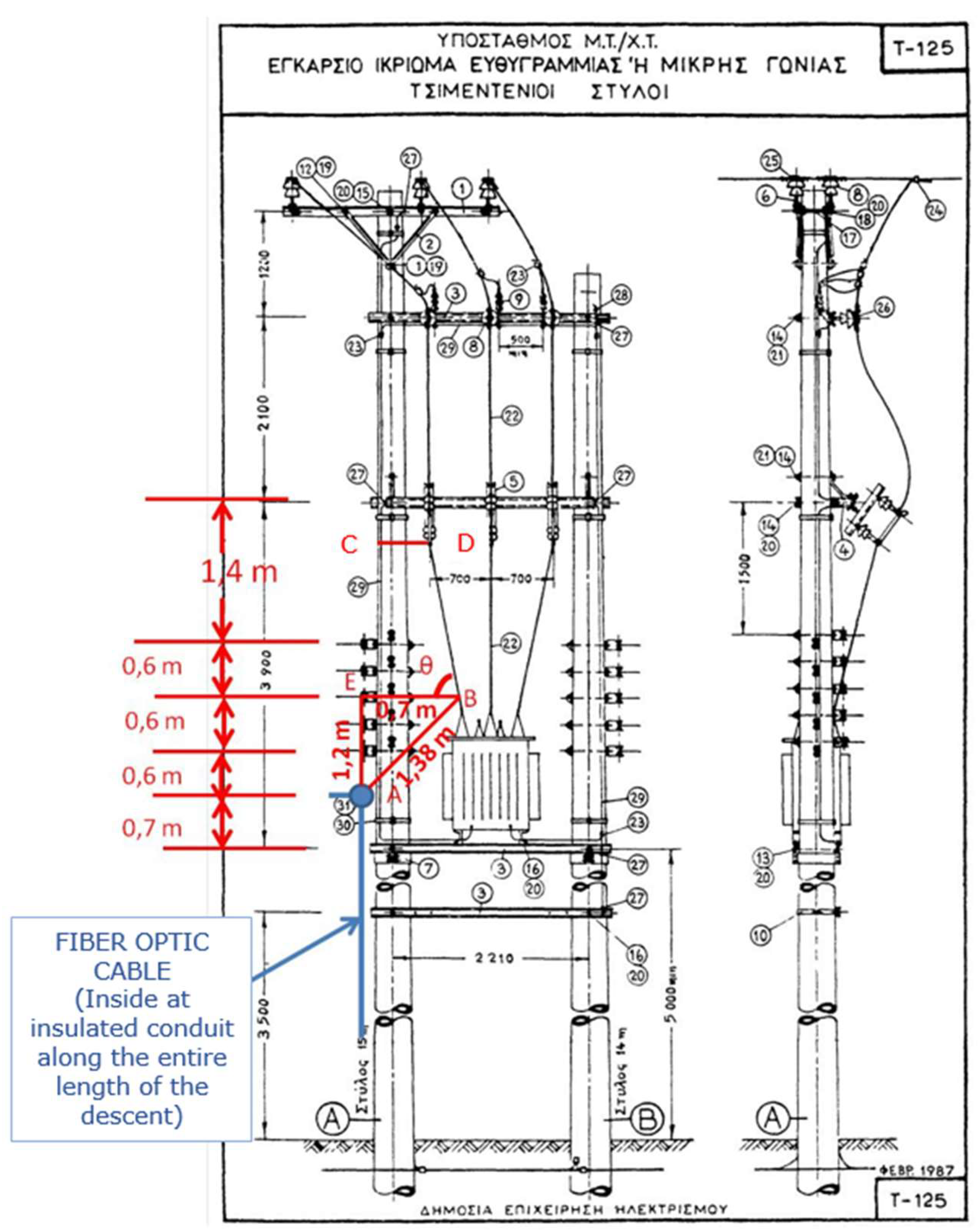
In the proposed arrangement for affixing fiber optic cables to the support structure of overhead MV/LV substations, the study emphasizes the importance of maintaining specific vertical distances for medium-voltage lines and fiber optic cables to ensure uninterrupted power supply. As delineated in ELOT EN 50174.03 and supplemented by previous research, a minimum vertical separation of 1.2 to 2 meters is necessary when these cables are installed parallel to each other. Additionally, the optical fiber is typically connected at a vertical distance of at least 0.6 meters below the city street lighting conductors, as illustrated in
Figure 4.
This configuration is shown to place the optical fiber at a height of 5.8-6.0 meters from the ground at substations, aligning with the standards set out in the “HEDNO Standardized Distribution Network Structures” (T125 and U117). However, the study also acknowledges the need for flexibility, suggesting that in terrain with unfavorable morphology, alternative support points for the optical fiber may need to be considered, especially following power outages.
Further detailed in the study, and as depicted in
Figure 4, is the arrangement of fiber optic cables in relation to medium voltage lines. The critical measurement of distance AB, set at 1.38 meters, exceeds the minimum requirements of Directive 15 and ELOT EN 50110. This measurement represents a non-parallel, angled arrangement of the cables (θ=84°), which is shown to significantly reduce electromagnetic interference by approximately 90%. This configuration is particularly beneficial in scenarios where the fiber optic cable is down and parallel to low and medium voltage cables, necessitating shielding and the use of insulating tubes to prevent risks such as sabotage or interference. Moreover, the study advises that when low-voltage overhead lines comprise twisted pair cables instead of bare conductors, the same suspension height for optical fibers (5.8 to 6.0 meters above ground) should be maintained, as indicated in the “HEDNO Standardized Distribution Network Structures” (July 2018 edition). This approach ensures consistent safety and operational standards across various cable types and configurations.
For this case, the team conducted a detailed study of the electrical parameters Z and Y across various vertical distances between the bare medium-voltage conductor and the optical fiber, considering distances of 0.7 m, 1 m, 1.2 m, 1.38 m, and 2 m. These parameters were assessed between the optical fiber sheath and three medium-voltage conductors, spaced 0.5 m apart, featuring a cross-section of 50 mm2 and an external diameter of 1.233 cm. The study specifically focused on the resistivity of the current-carrying conductors, identified as ACSR (2.65 * 10^-8 Ωm), and explored various resistivity scenarios for the optical fiber sheath, as reported in the literature, ranging from 10^-7 Ωm to 10^6 Ωm. Special attention was given to the scenario of low resistivity (10^-7 Ωm), considered the most challenging. Key parameters like sheath resistance, conductivity, mutual resistances, and transverse conductances were analyzed to understand their impact on induced voltages and currents. While the detailed results of these investigations are documented, this paper will discuss the implications and applications of these findings without displaying the complete data but only the key points.
The comprehensive analysis conducted reveals significant insights into the impedance characteristics of fiber optic cables when positioned at varying distances from the nearest medium-voltage (MV) conductor. These results delineate the impedance per unit length, both real (ohmic resistance) and imaginary (inductive reactance), for fiber distances of 0.7 m, 1.0 m, 1.2 m, 1.38 m, and 2.0 m from the MV conductor, across two distinct frequencies: 50 Hz and 1 MHz. Notably, the fiber cladding resistivity was set at 10^-7 Ωm for these measurements.
A key finding from this analysis (
Table 4) is the substantial reduction in electromagnetic interaction when the fiber optic cable and MV line are not in parallel but positioned at an 84-degree angle (θ=84ο), as illustrated in Fig. 4. This angular arrangement leads to a reduction in interference by approximately 90%, a significant improvement over the 33.16% increase observed otherwise. This reduction is particularly noteworthy when considering the impact on dry arcing and micro-scintillations, suggesting that a relative distance AB of 1.38 m, as opposed to the 2 m recommended by EN50174.3, does not contribute to these effects.
Further examination of transverse conductivities (
Table 5) highlights the impedance characteristics at the same fiber distances and frequencies.
Here, the real part of the impedance is negligible, with the imaginary part representing the -jωC term. These comparative tables reaffirm the findings from the previous analysis, showing that the angular positioning of the optical fiber relative to the MV line significantly reduces the likelihood of the corona effect and capacitive current effects.
This result strengthens the argument for a reduced relative distance AB of 1.38 m compared to the standard 2 m, as it does not contribute to these detrimental effects, even under conditions of high frequency and low resistivity.
These findings play a crucial role in guiding the optimal installation and maintenance of fiber optic cables in proximity to medium-voltage lines.
7. Proposed Arrangement for Fixing Fiber Optic Cables to the Support Structure of Overhead MV/LV Substations Without Interruption of Power Supply
In this section addressing safety issues related to aerial IT and power cable separation at medium voltage levels, various regulations and standards are considered to ensure safe working conditions. Directive 15 classifies working within 0.76 m of medium voltage conductors as near medium voltage installations. ELOT EN 50110 and IEEE 2023 NECS set similar parameters, with safe work distances defined as more than 0.22 m and 1.20 m respectively from medium-voltage conductors. Consequently, the installation and maintenance of optical fibers at distances exceeding 1.25 m from MV/LV substation conductors are recommended, aligning with the classification of work near medium voltage installations for telecommunications workers. This applies regardless of whether the distance AB is parallel or diagonal to the ground.
For such work, personnel must possess the requisite certified training and experience, in line with national legislation (for example PRESIDENTIAL DECREE 108/13 for Greek legislation) and be under continuous supervision of a higher-grade installer. This supervisor is responsible for assessing work feasibility, considering various factors like weather conditions and potential proximity changes during operations.
Essential safety measures for this work include constant supervision by an authorized senior assembler, use of an insulated bucket trolley, favorable environmental conditions, and appropriate personal protective equipment. Additional safety precautions may include insulating covers and exclusively using insulated tools and equipment. Before proceeding, it is crucial to ensure that fiber stretching does not compromise operational limits and clearances. If these conditions are not met, the work should be conducted with the power switched off to maintain safety standards.
8. Conclusions
The main conclusions of this document focus on the electromagnetic compatibility and interference, installation procedures, support distances, and safety measures for installing optical fiber cables near or on power supply cables, particularly in HEDNO's overhead MV/LV substations. Key proposals include:
Fiber optic cables near or on power supply cable of HEDNO where two scenarios are considered and mounting fiber-optic cables to overhead substation support structure.
Furthermore, if a clearance of 5.0 m from the ground cannot be maintained, a legislative amendment may be necessary, allowing the suspension of optical fiber at a reduced distance of 0.30 m below the conductor. The installation activities must comply with the safety standards outlined in Directive 15 and ELOT EN 50110, categorizing work as near medium or low voltage installations based on proximity.
Personnel involved in these installations must have certified training and be supervised by a higher-level installer. This supervisor assesses work feasibility, considering environmental conditions and potential proximity changes during operations. Essential safety measures include constant supervision, use of insulated tools and equipment, and adherence to appropriate personal protective equipment standards. If safety conditions are not met, work should be conducted with the power switched off to ensure safety.
Funding
This work was supported in part by the Hellenic Distribution Network Operator (HEDNO) under Grant SAP 6000012158/23.06.2023.
Acknowledgments
The authors would like to greatly thank Mr. Stefanos Beis, head of the dept. of Network Studies of HEDNO and Mr. Panagiotis Liontos, Head of Network Administration of HEDNO, for their trust and assistance throughout the project.
Conflicts of Interest
“The authors declare no conflicts of interest”
References
- EN 50174.03, 2nd edition, 2013-10-18: “Information technology - Cabling installation - Part 3: Installation planning and practices outside buildings”.
- 2023 NATIONAL ELECTRICAL SAFETY CODE® (NESC®), C2-2023,” IEEE Standards Association.
- D. J. Marne, “National Electrical Safety Code (NESC) 2017 Handbook,” 4th ed. New York, NY: McGraw-Hill Education. ISBN 978-1259584152.
- “2023 NESC® Handbook”, IEEE Standards Association.
- “Greek Regulation of Installations and Maintenance of outdoor overhead power lines,” Government paper section B’ 608, 06/10/1967, pp. 4623, table No11.
- Directive No15, HEDNO, 1976.
- HEDNO Standardized Distribution Network Structures, 1974-2018.
- EN 50110.01 Ε3, 2013-03-15: “Operation of electrical installations - Part 1: General requirements”.
- "Analysis and Documentation of Installation Conditions for an Overhead Fiber Optic Network on HEDNO's Electrical Distribution Poles," a contractual deliverable from the HEDNO-INNORA agreement No 6000010788/27.10.2022, dated October 2022.
- F. D. Surianu and A. Pana, “Fiber Optic Cable Mounted on Common Poles with a Medium Voltage Overhead Line Standardizing Procedure,” 19th Telecommunications forum TELFOR 2011, Serbia, Belgrade, Nov. 22-24, 2011.
- “Requirements for the Attachment of Communication Cable Facilities on PPL Poles,” 6-01-140 – Utility Reference Specification – Attachment of Communication Cable Facilities on PPL Poles, PPL Electric Utilities, Effective Date: 05/04/2020, pp. 120 of 174.
- G. G. Karady, M. G. G. Karady, M. Torgerson, D. Torgerson, J. Wild, and M. W. Tuominen, “Evaluation of corona-caused aging of ADSS fiber-optic cables,” in IEEE Transmission and Distribution Meeting, 1999, Paper#TR08-080.
- G. Carlton, A. G. Carlton, A. Bartlett, C. Carter, and T. Parkin, “UK power utilities’ experience with optical telecommunications cabling systems,” Power Engineering Journal, vol. 9, pp. 7–14, Feb. 1995.
- R.G. Olsen, “An improved model for the electromagnetic compatibility of all-dielectric self-supporting fiber-optic cable and high-voltage power lines”, IEEE Transactions on Electromagnetic Compatibility (Vol. 41, Issue: 3, Aug. 1999.
- M. W. Tuominen and R. G. Olsen, “Electrical Design Parameters of All-Dielectric-Self-Supporting Fiber Optic Cable,” IEEE Transactions on Power Delivery, (vol. 15, no. 3, July 2000).
- D. A. Tsiamitros, G. C. D. A. Tsiamitros, G. C. Christoforidis, G. K. Papagiannis, D. P. Labridis, P. S. Dokopoulos, “Earth Conduction Effects in Systems of Overhead and Underground Conductors in Multilayered Soils,” IET Proceedings on Generation, Transmission & Distribution, Vol. 153, No. 3, pp. 291-299, 2006.
- G. K. Papagiannis, D. A. G. K. Papagiannis, D. A. Tsiamitros, D. P. Labridis, P. S. Dokopoulos, “A Systematic Approach To The Evaluation Of The Influence Of Multi-Layered Earth On Overhead Power Transmission Lines,” IEEE Transactions on Power Delivery, Vol. 20, No 4, pp. 2594-2601, 2005.
- D. A. Tsiamitros, G. K. D. A. Tsiamitros, G. K. Papagiannis, D. P. Labridis, P. S. Dokopoulos, “Earth Return Impedances of Underground Cables for the Two-Layer Earth Case,” IEEE Trans. Power Delivery, Vol. 20, No. 3, pp. 2174-2181, 2005.
- D. A. Tsiamitros, G. K. D. A. Tsiamitros, G. K. Papagiannis, P. S. Dokopoulos, “Earth Return Impedances of Conductor Arrangements in Multi-Layer Soils—Part I: Theoretical Model,” IEEE Trans. Power Delivery, Vol. 23, No. 4, pp. 2392-2400, 2008.
- D. A. Tsiamitros, G. K. D. A. Tsiamitros, G. K. Papagiannis, P. S. Dokopoulos, “Earth Return Impedances of Conductor Arrangements in Multi-Layer Soils—Part II: Numerical Results,” IEEE Trans. Power Delivery, Vol. 23, No. 4, pp. 2401-2408, 2008.
- “AERIAL COMMUNICATION CABLE IDENTIFICATION GUIDE”, As prepared by KCI Technologies, Inc., November 2021.
- “All-Dielectric Self-Supporting (AFL-ADSS®) Fiber Optic Cable,” AFLglobal.com.
- “AERIAL FIBER OPTICS - OPGW & ADSS,” SUPREME& CO. PVT. LTD.
- “Clearance Adherence: Avoiding Mid-span Violations,” [Online]. Available:https://www.leidos.com/insights/clearance-adherence-avoiding-mid-span-violations.
- “Joint Use Guide TECI,” 07/23/2019, Taylor Electric Cooperative Inc., Purpose and Scope.
- "Technical Specifications for the Construction of Telecommunication Network Projects," O.T.E., Version 10-2012.
- Flavius Dan Surianu, Member, IEEE, Adrian Pana, “Fiber Optic Cable Mounted on Common Poles with a Medium Voltage Overhead Line Standardizing Procedure”, 19th Telecommunications forum TELFOR 2011, Serbia, Belgrade, November 22-24, 2011.
|
Disclaimer/Publisher’s Note: The statements, opinions and data contained in all publications are solely those of the individual author(s) and contributor(s) and not of MDPI and/or the editor(s). MDPI and/or the editor(s) disclaim responsibility for any injury to people or property resulting from any ideas, methods, instructions or products referred to in the content. |
© 2024 by the authors. Licensee MDPI, Basel, Switzerland. This article is an open access article distributed under the terms and conditions of the Creative Commons Attribution (CC BY) license (https://creativecommons.org/licenses/by/4.0/).