1. Introduction
Bolt connections, the most prevalent form of fastener connection, are extensively utilized across various industrial sectors including machinery, aviation, and power[
1,
2]. For example, a significant number of bolts can be found in components such as transmission line suspension clamps and transmission towers[
3]. During equipment operation, factors such as vibrations, impacts, and alternating loads inevitably cause the connecting bolts to loosen or dislodge[
4], potentially leading to severe accidents. This not only results in substantial economic losses but also poses a serious threat to human safety[
5,
6]. Consequently, the identification of a straightforward yet effective method to prevent threaded connections from loosening has emerged as an urgent issue requiring resolution.
Shape Memory Alloy (SMA) is a functional material renowned for its ability to revert to its original shape under specific conditions[
7,
8]. This unique property primarily arises from its thermoelastic martensitic phase transformation, enabling reversible alterations in the crystal structure with temperature fluctuations[
9,
10]. The inherent shape memory effect and superelasticity of SMA confer substantial benefits in the realm of anti-loose devices[
11,
12]. In this study, we design an anti-loose gasket utilizing SMA. Employing the ABAQUS finite element software, we conduct stress and deformation analyses on the SMA anti-loose gasket to assess its performance across various sizes and shapes.
2. Design of Ni-Ti Shape Memory Alloy Anti- Loose Gasket
Shape memory alloys represent a novel class of functional metallic materials. These alloys possess an inherent initial shape and can revert to this original form when exposed to stimuli such as heat, light, or electricity following low-temperature deformation[
13]. Notably, Ni-Ti shape memory alloys stand out within this group. Composed of binary nickel and titanium alloys, they not only exhibit the shape memory effect but also demonstrate exceptional superelasticity.
The Ni-Ti shape memory alloy exhibits a unique property whereby it can fully recover from large nonlinear deformations once the external force is removed[
14]. This remarkable characteristic stems from the martensitic phase transformation that takes place during loading, and its reverse during unloading[
15]. This superelastic effect enables the shape memory alloy to swiftly revert to its original state post-stress, thereby demonstrating superior elasticity and recovery capabilities. Such a feature renders the Ni-Ti shape memory alloy an ideal candidate for the fabrication of high-performance anti-loose gaskets[
16]. The chemical composition of the shape memory alloy used in the manufacture of the gasket discussed in this paper is detailed in
Table 1, with a thickness of 2mm.
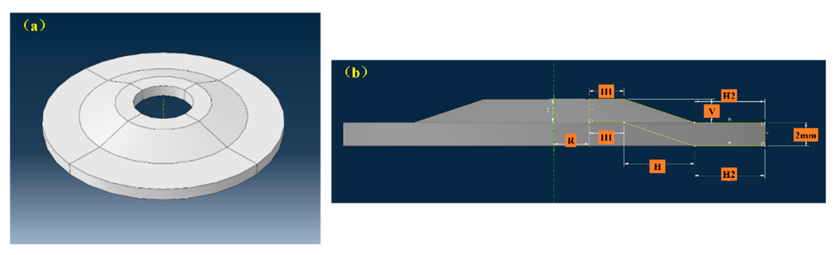
The design of an anti-loose gasket was illustrated in
Figure 1(a). The gasket's inner hole diameter, the transverse distance of its bent section, the difference between the inner and outer radii of the upper contact surface annulus, the difference between the inner and outer radii of the lower contact surface annulus, and the upper convex thickness are denoted as R, H, H1, H2, and V respectively (as depicted in
Figure 1(b)).
3. Establishment of the Finite Element Model for Anti-Loose Gaskets
In order to optimize the shape and size of the gasket, this paper uses the general engineering finite element simulation software ABAQUS to numerically simulate the deformation and stress distribution of the gasket under force.
3.1. Calculation Model and Mesh Generation
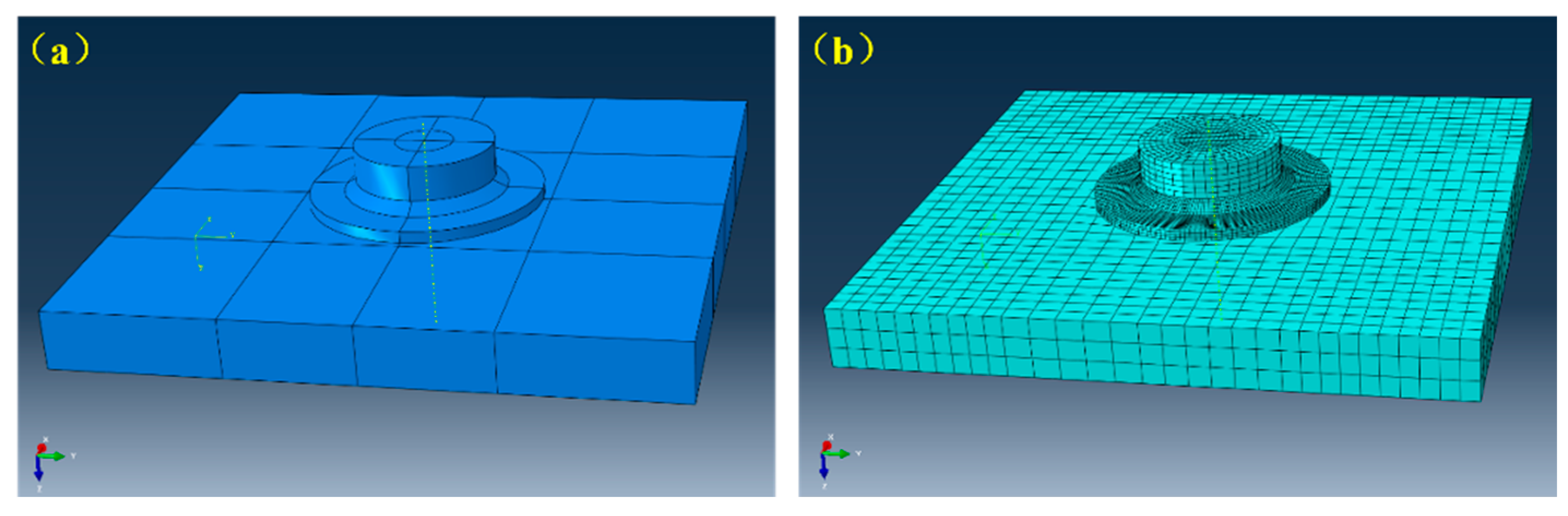
In numerical simulations, the computational domain encompasses three distinct components: the gasket, the bolt, and the perforated steel plate. Utilizing ABAQUS's integrated modeling module, these individual "parts" are meticulously created and subsequently assembled to construct the comprehensive structural model[
17].
With the inner hole diameter (R) of the gasket set at 4 mm, the convex thickness (V) on the bent section at 2 mm, the transverse distance (H) at 6 mm, the difference in inner and outer radii (H1) of the upper contact surface at 3 mm, the difference in inner and outer radii (H2) of the lower contact surface at 6 mm, the bolt size as M8 standard, and the steel plate dimensions at 500mm×500mm×10mm, the resulting structural model is depicted in
Figure 2(a).
In the transient dynamic analysis of large deformation or high-speed dynamic loading, the C3D8R eight-node tetrahedral element demonstrates superior computational accuracy and convergence[
18,
19]. This study employs this element to execute "reduced integration" meshing on the structural model[
20,
21]. To minimize computational demands, the mesh size for the gasket component is reduced, while those for the bolts and steel plates are marginally larger[
22,
23], yielding the computational mesh depicted in
Figure 2(b).
3.2. Material properties
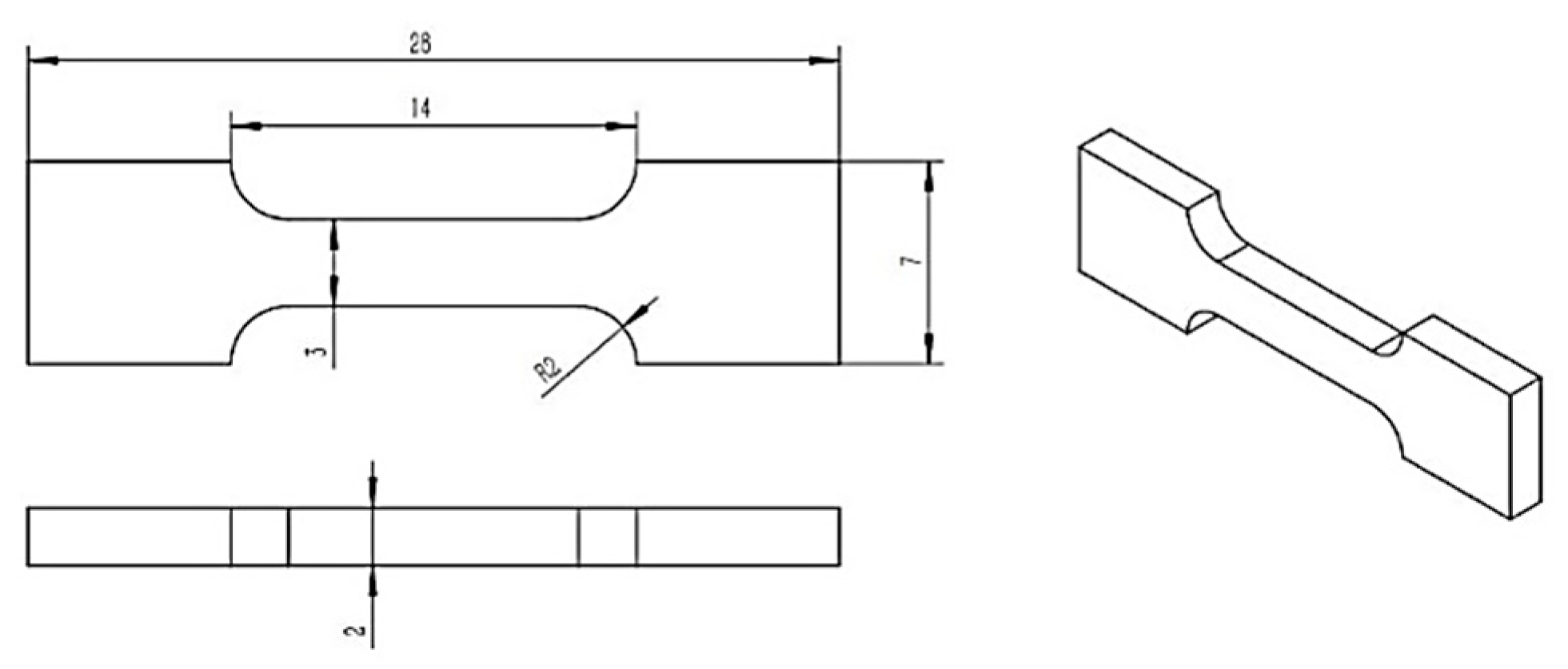
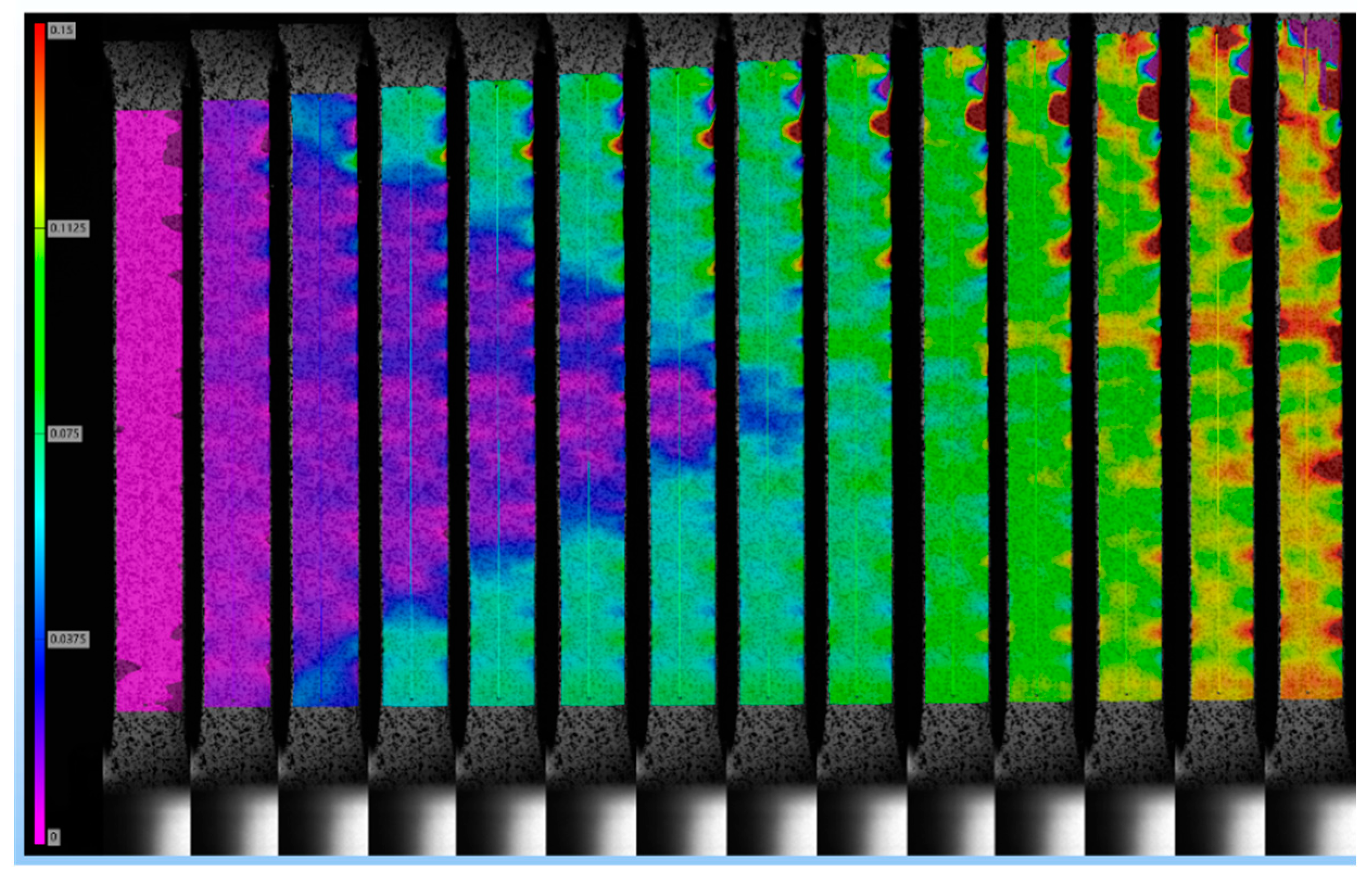
Three specimens were meticulously cut from a Ni-Ti shape memory alloy plate, adhering to the dimensions illustrated in
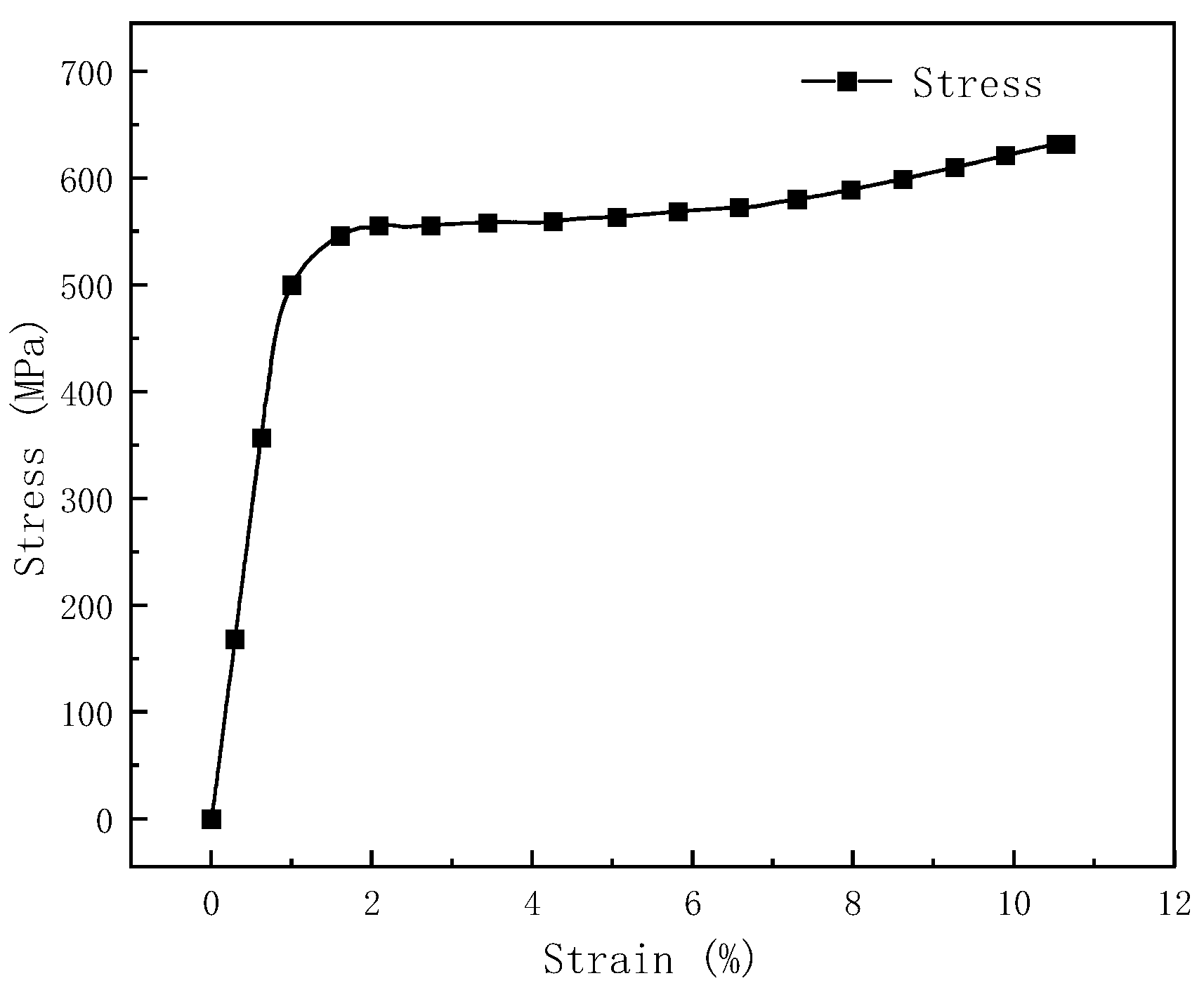
Figure 3, utilizing an electrical discharge wire cutting machine. Tensile tests were conducted on these specimens using the CMT-30 electronic universal testing machine at a strain rate of 2%/min. The LVE-5M PRO DIC video extensometer was employed to accurately measure the real-time major strain distribution of the specimens, as depicted in
Figure 4. The resulting stress-strain curve of the material is presented in
Figure 5.
The stress-strain curve was analyzed using Origin software, revealing an elastic modulus for the material of 584.08 GPa and a yield strength approximating 552 MPa. The phase transformation from austenite to martensite commences at approximately 1.85% strain. By the time the strain reaches 6.52%, the material's structure has fully transformed into martensite.
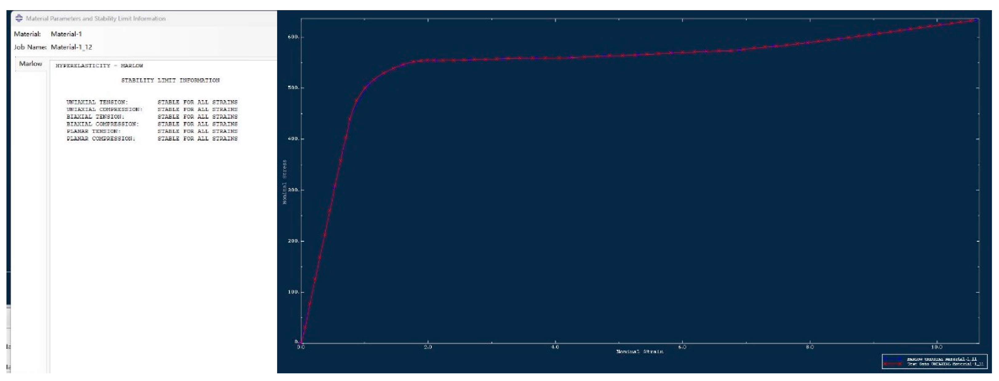
The stress-strain data for the Ni-Ti shape memory alloy was incorporated into the "Property" module of ABAQUS software. We employed all superelastic constitutive models, namely Polynomial, Ogden, Reduced Polynomial, Arruda-Boyce, Van Der Waals, and Marlow, to assess the data[
24,
25]. Models exhibiting substantial deviations between fitted and test data were systematically excluded, leading to re-evaluation. The outcomes of this assessment are presented in
Figure 6. It clearly indicates that the Marlow model aligns closely with the tensile test data for the nickel-titanium shape memory alloy. Consequently, the material test data as interpreted by the Marlow model is designated as the " superelastic" property for subsequent computations.
The bolts and steel plates were fabricated from standard 304 stainless steel, ensuring consistent material properties throughout the experiment.
3.3. Boundary and loading conditions
The gasket, bolt, and perforated steel plate are aligned with "concentric" constraints. The upper surface of the gasket is in "frictional contact" with the underside of the bolt head, while its lower surface makes "frictional contact" with the top surface of the steel plate. The outer cylindrical surface of the bolt shank engages in "frictional contact" with the inner cylindrical surfaces of the holes present in both the gasket and the steel plate. A sliding friction coefficient of 0.2 is assigned to each contacting surface. The bottom surface of the perforated steel plate is "rigidly fixed."
The simulation calculation employs a distributed loading method, segmenting the entire force process into three distinct stages: "pre-tightening", "tightening", and "unloading". The displacement of the contact surface between the bolt head and the gasket serves as the control variable. A downward movement of 0.1mm of this surface is categorized as "pre-tightening", while a downward movement of 1mm is classified as "tightening". Finally, resetting the displacement of this surface to zero is defined as "unloading".
3.4. Stress and deformation calculation results
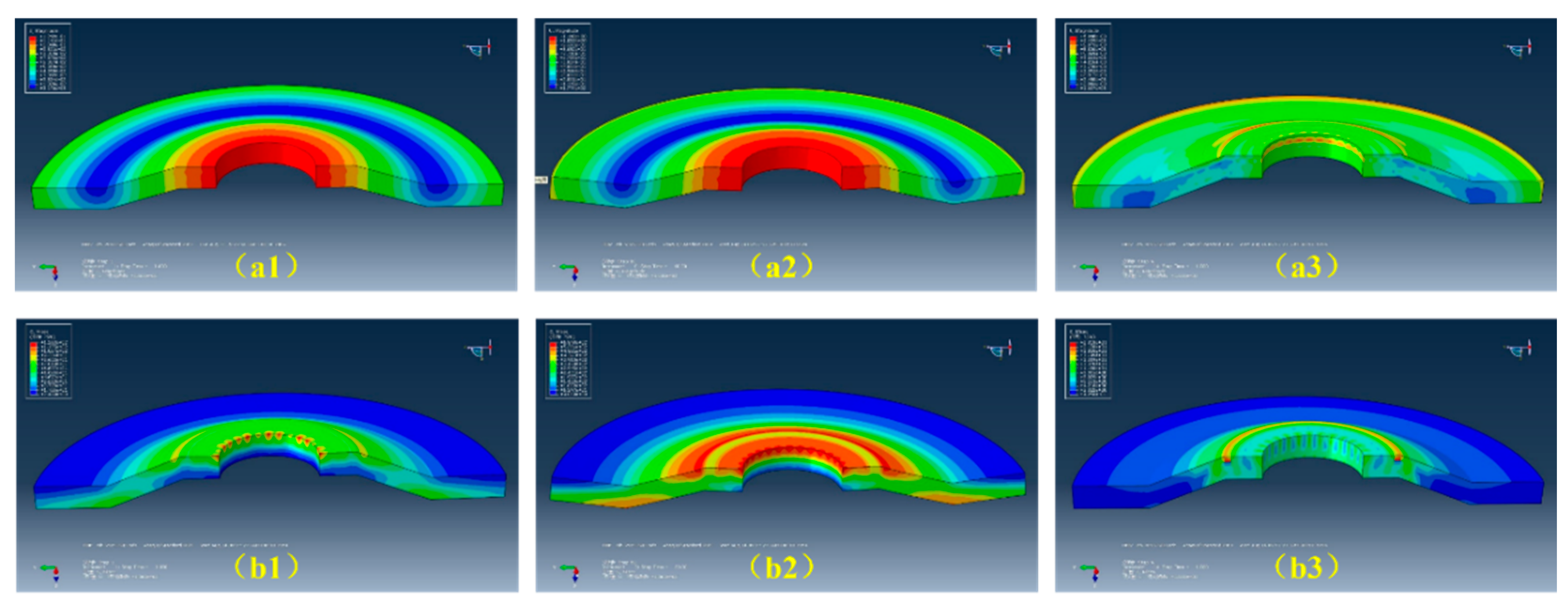
Upon completion of the calculations, deformation and stress cloud diagrams for the gasket throughout the "pre-tightening - tightening - unloading" stages are derived, as depicted in
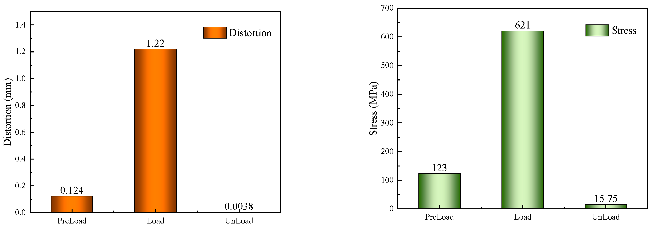
Figure 7. This is viewed from the longitudinal section of the gasket. The progression of deformation and stress at the contact point between the upper surface of the gasket and the screw rod during these three stages is illustrated in
Figure 8.
The Figure illustrates that the deformation and stress of the gasket during the three stages - pre-tightening, tightening, and unloading - are axially symmetrical. The maximum deformation and stress occur at the intersection of the gasket, bolt head, and screw rod during the loading phase. Post unloading, the peak residual stress and deformation are found at the gasket's "shoulder". Upon complete unloading, the residual deformation and stress of the gasket are minimal. This suggests that the superelasticity characteristic of the Ni-Ti shape memory alloy provides a significant advantage in the manufacture of anti-loose gaskets.
4. Optimization Design of Anti-Loose Gasket Shape
4.1. The effect of thickness
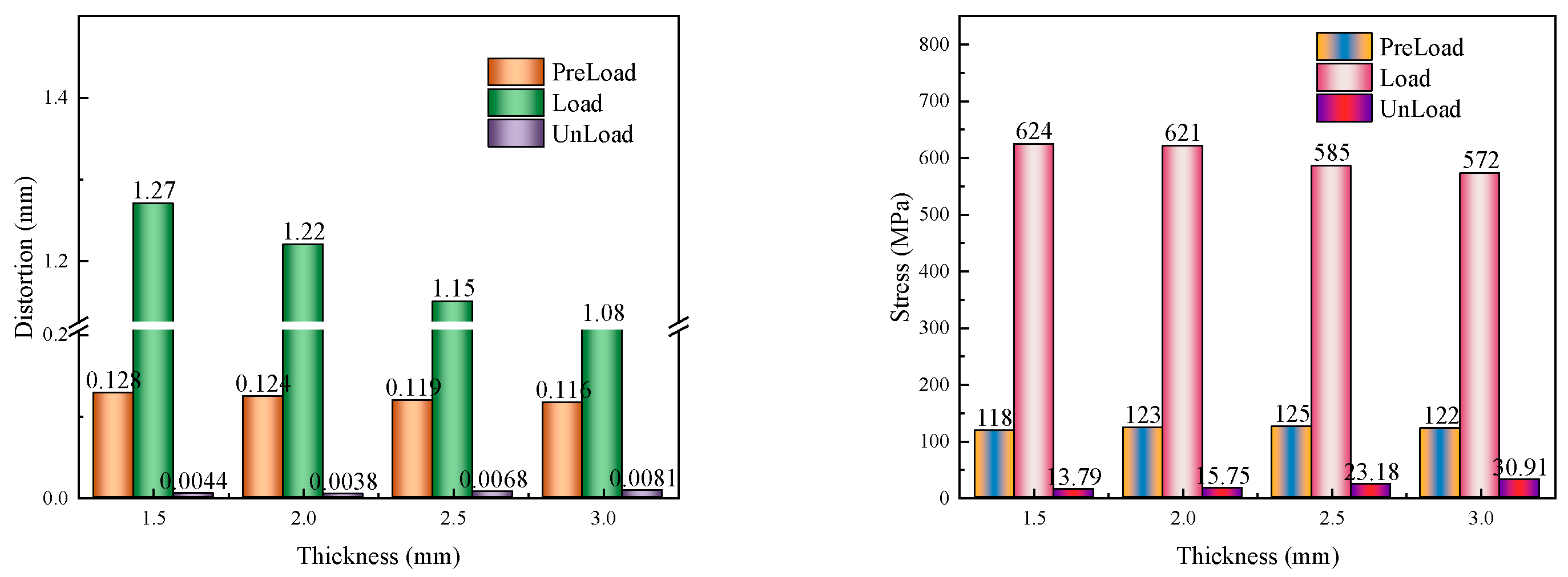
While keeping other parameters constant, the convex thickness (V) of the gasket's bent section is adjusted to 1.5mm, 2.0mm, 2.5mm, and 3.0mm respectively. For each setting, structural models are developed and meshed for recalculation. Numerical calculations and statistical analysis reveal the progression of deformation and stress on the gasket's contact surface relative to the screw position during the three stages of "pre-tightening - tightening - unloading". These findings are illustrated in
Figure 9.
The graph illustrates that an increase in the convex thickness of the bend section on the gasket during the "pre-tightening" phase results in a minor decrease in gasket deformation, while stress initially exhibits a slight increase, followed by a minor decrease. In the subsequent "tightening" phase, both the deformation and stress of the gasket demonstrate a significant reduction. During the "unloading" phase, the residual stress within the gasket progressively escalates, whereas the residual deformation initially displays a minor decline, subsequently increasing to reach its nadir at a thickness of 2.0mm.
4.2. The effect of inclination
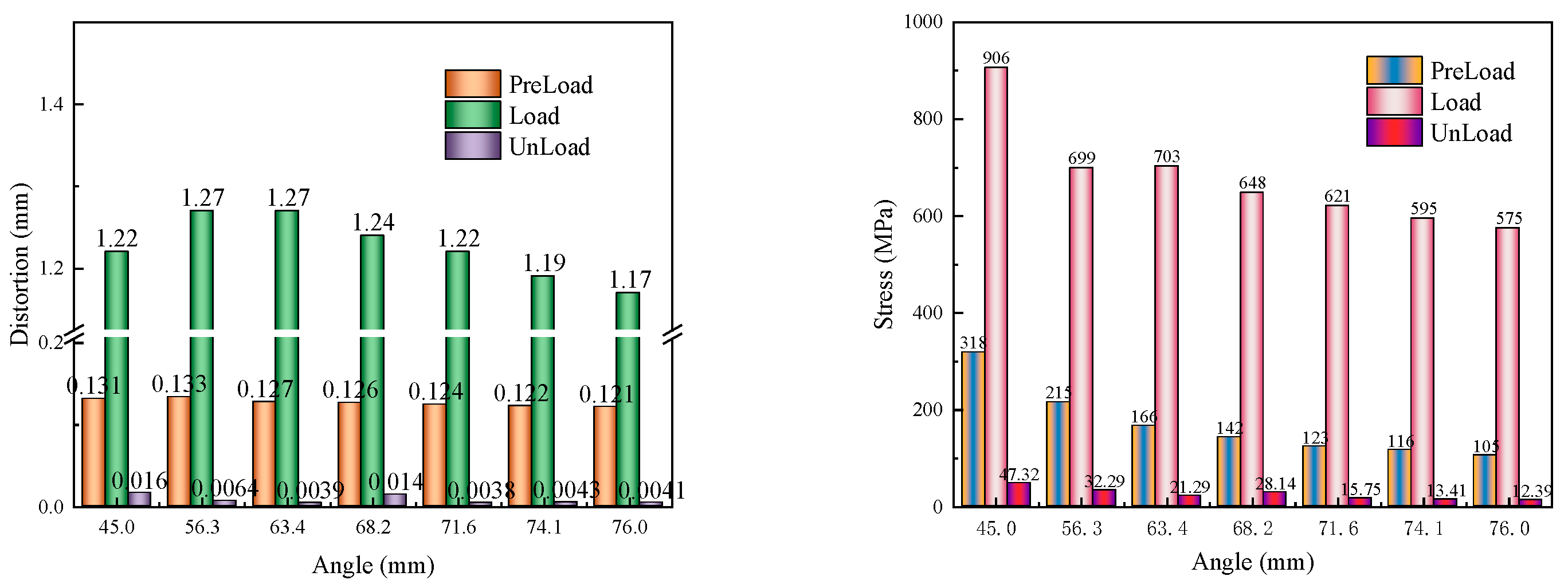
With other parameters remaining unchanged, when the transverse distance H of the bending section of the gasket is set to 2.0mm, 3.0mm, 4.0mm, 5.0 mm, 6.0mm, 7.0mm, and 8.0mm respectively, the bending angles of the gasket are 45.0°, 56.3°, 63.4°, 68.2°, 71.6°, 74.1°, and 76.0° respectively. Structural models were established for each and meshed for recalculation. Through numerical calculations and result statistics, the evolution of deformation and stress on the contact surface of the gasket with the screw during the "pre-tightening - tightening - unloading" three stages is shown in
Figure 10.
From the graph, it can be observed that as the bending angle increases, during the "pre-tightening" phase, the deformation of the gasket slightly decreases, and the stress noticeably reduces step by step. In the "tightening" phase, the deformation of the gasket first increases and then decreases, with the stress gradually reducing. During the "unloading" phase, the residual deformation of the gasket first decreases, then increases, and finally decreases again, while the residual stress continuously diminishes.
4.3. Influence of the outer diameter of the upper contact surface
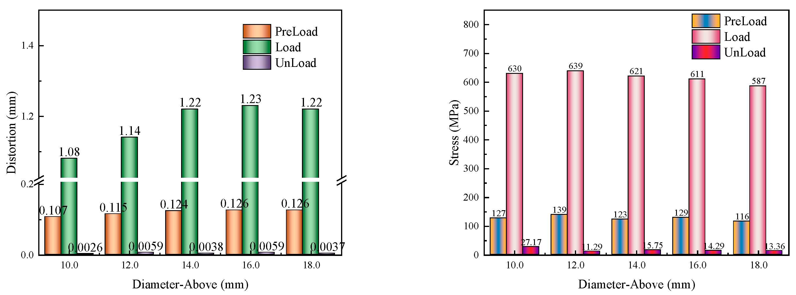
With other parameters remaining unchanged, the difference in the inner and outer radii of the annular contact surface on the gasket, H1, is set to 1mm, 2mm, 3mm, 4mm, and 5mm respectively. At this time, the outer diameters of the contact surface on the gasket are 10mm, 12mm, 14mm, 16mm, and 18mm respectively. Structural models are established and meshed for recalculation. Through numerical calculations and result statistics, the evolution of deformation and stress on the gasket's contact surface with the screw during the "pre-tightening - tightening - unloading" three stages is shown in
Figure 11.
From the graph, it can be observed that as the outer diameter of the upper contact surface increases, during the "pre-tightening" phase, the deformation of the gasket gradually increases, with little change in stress and slight fluctuations; in the "tightening" phase, the deformation of the gasket first increases and then stabilizes, while the stress gradually decreases; in the "unloading" phase, the residual deformation of the gasket changes slightly with minor fluctuations, and the overall trend of the residual stress is to gradually decrease.
4.4. Influence of the outer diameter of the lower contact surface
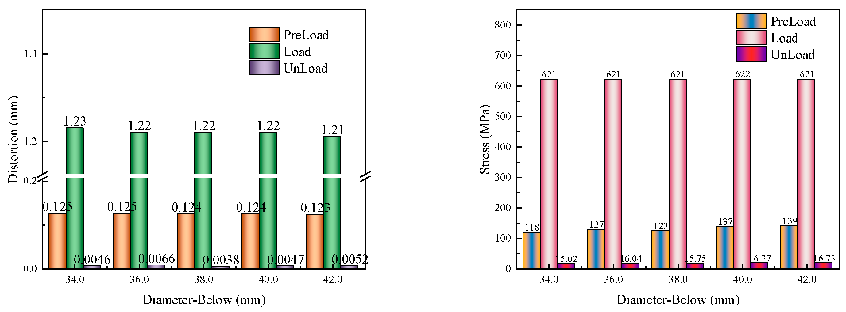
All parameters were kept constant except for the difference in inner and outer radii of the annulus on the contact surface under the gasket (H2). When H2 was set to 4.0mm, 5.0 mm, 6.0mm, 7.0mm, and 8.0mm respectively, the corresponding outer diameters of the contact surface under the gasket were 34mm, 36mm, 38mm, 40mm, and 42mm. For each of these settings, structural models were developed and meshed for recalculation. The numerical calculations and result statistics revealed the evolution of deformation and stress on the contact surface of the gasket with the screw during the three stages of "pre-tightening - tightening - unloading". This information is visually represented in
Figure 12.
The graph illustrates that an increase in the outer diameter of the lower end face during the "pre-tightening" phase initially results in minor fluctuations in gasket deformation, with stress levels first decreasing slightly, then increasing. In the subsequent "tightening" phase, there are negligible differences in both deformation and stress of the gasket. During the "unloading" phase, a similar pattern is observed for both residual deformation and stress, where they initially decrease slightly, before increasing once more. Notably, when the difference between the inner and outer radii of the annular contact surface on the lower side measures 6mm, the residual deformation reaches its minimum value.
In evaluating the gasket's design, both technical and production indicators were taken into account. These include factors such as gasket deformation, stress, processing, and assembly. The size parameters of the gasket are thus determined as follows: The internal diameter (R) is contingent upon construction conditions. The convex thickness of the bent section measures between 2mm and 3mm, while the lateral distance of this section ranges from 4mm to 7mm. This results in a bending angle for the gasket of approximately 60° to 70°. Furthermore, the difference between the inner and outer radii of the upper contact surface ring is between 2mm and 4mm, with the lower contact surface ring exhibiting a minimum difference of 2mm between its inner and outer radii.
5. Conclusion
(1) This study employs a finite element model, utilizing ABAQUS software to numerically simulate the deformation and stress experienced by Ni-Ti shape memory alloy anti-loose gaskets throughout three stages: pre-tightening, tightening, and unloading. The research reveals that the deformation and stress within the gaskets during these stages are axially symmetrically distributed.
(2) During the loading phase, the maximum deformation and stress occur at the intersection of the gasket, bolt head, and screw rod. Upon unloading, the peak residual stress and deformation are located at the "shoulder" of the gasket.
(3) The load-deformation characteristics of the designed gasket are influenced by its size parameters. Considering technical aspects such as deformation and stress, along with production factors like processing and assembly, the following size parameters for the gasket have been established: The inner diameter (R) is dictated by construction conditions; the convex thickness of the bent section ranges from 2mm to 3mm; the lateral distance of this section spans 4mm to 7mm, resulting in a bending angle of approximately 60° to 70°; the disparity between the inner and outer radii of the upper contact surface ring is between 2mm and 4mm; and for the lower contact surface ring, this difference is at least 2mm.
Author Contributions
Conceptualization: Li Xinmei and Suo Shuai; Methodology: Xue Tianxiang; Software: Suo Shuai and Li Wen; Formal Analysis: Bu Yanjiang and Wu Dongting ; Writing – Original Draft Preparation, Li Xinmei and Xue Tianxiang; Writing – Review & Editing: Li Wen and Bu Yanjiang; Supervision: Li Xinmei and Wu Dongting.
Acknowledgments
We would like to thank Prof. Zou Yong and Prof. Wang Xiebin of Shandong University for their theoretical guidance and experimental support of our research work.
Conflicts of Interest
The authors declare no conflict of interest.
References
- Zhai, S.-Y.; Lyu, Y.-F.; Cao, K.; Li, G.-Q.; Wang, W.-Y.; Chen, C. Seismic behavior of an innovative bolted connection with dual-slot hole for modular steel buildings. Engineering Structures 2023, 279. [Google Scholar] [CrossRef]
- Wang, Y.Q.; Xing, W.C.; Wang, J.; Chai, Q. Theoretical and experimental studies on vibration characteristics of bolted joint multi-plate structures. International Journal of Mechanical Sciences 2023, 252. [Google Scholar] [CrossRef]
- Ding, Y.; Chung, K.F.; Tong, C.C.; Wang, X.D.; Zhou, X.H.; Elghazouli, A.Y. Behaviour of large-diameter high-strength bolted shear connections for prefabricated composite beams. Engineering Structures 2025, 322. [Google Scholar] [CrossRef]
- Koch, G.; Posazhennikova, A. Loop current states and their stability in small fractal lattices of Bose-Einstein condensates. Physical Review A 2024, 110. [Google Scholar] [CrossRef]
- Ozarde, A.P.; McNay, G.; Gautam, S.S. Fretting Fatigue Failures in Internal Combustion Engine Components: A Review and Future Scope. Sae International Journal of Engines 2021, 14, 211–234. [Google Scholar] [CrossRef]
- Nelson, N.R.; Prasad, N.S.; Sekhar, A.S. Structural integrity and sealing behaviour of bolted flange joint: A state of art review. International Journal of Pressure Vessels and Piping 2023, 204. [Google Scholar] [CrossRef]
- Dudek, K.; Goryczka, T.; Dulski, M.; Psiuk, B.; Szurko, A.; Lekston, Z. Functionalization of the Implant Surface Made of NiTi Shape Memory Alloy. Materials 2023, 16. [Google Scholar] [CrossRef]
- Wang, X.; Yu, J.; Liu, J.; Chen, L.; Yang, Q.; Wei, H.; Sun, J.; Wang, Z.; Zhang, Z.; Zhao, G.; et al. Effect of process parameters on the phase transformation behavior and tensile properties of NiTi shape memory alloys fabricated by selective laser melting. Additive Manufacturing 2020, 36. [Google Scholar] [CrossRef]
- Ben Fraj, B.; Zghal, S. Correlation between Hardness Behavior, Shape Memory, and Superelasticity in Ni-Rich NiTi Shape Memory Alloy. Journal of Materials Engineering and Performance 2024. [Google Scholar] [CrossRef]
- Vashishtha, H.; Collins, D.M. The influence of dislocations on B19' and R-phase transformations in a NiTi shape memory alloy. Scripta Materialia 2025, 255. [Google Scholar] [CrossRef]
- Lu, X.; Li, G.; Liu, L.; Zhu, X.; Tu, S.-T. Effect of Aging Treatment on the Compressibility and Recovery of NiTi Shape Memory Alloys as Static Seals. Journal of Materials Engineering and Performance 2017, 26, 3025–3033. [Google Scholar] [CrossRef]
- Qiang, X.; Shu, Y.; Jiang, X.; Wang, M.; Guo, J. Theoretical investigation and design recommendations for the initial stiffness of Fe-SMA/steel bolted joints in shear. Engineering Failure Analysis 2024, 158. [Google Scholar] [CrossRef]
- Zhang, J.T.; Ding, H.; Cai, M.H.; Zhang, N.; Qu, H.T.; Li, S.X.; Hou, H.L.; Cao, P. Nanostructured NiTi Shape Memory Alloy Via Ni/Ti Nanolamination. Metallurgical and Materials Transactions a-Physical Metallurgy and Materials Science 2020, 51, 1051–1055. [Google Scholar] [CrossRef]
- Carbonaro, D.; Villa, E.; Gallo, D.; Morbiducci, U.; Audenino, A.L.; Chiastra, C. Designing the mechanical behavior of NiTi self-expandable vascular stents by tuning the heat treatment parameters. Journal of the Mechanical Behavior of Biomedical Materials 2024, 158. [Google Scholar] [CrossRef]
- Hu, S.; Alam, M.S.; Zhang, Y.; Ding, Z.; He, X. Partially self-centering braces with NiTi- and Fe-SMA U-shaped dampers. Thin-Walled Structures 2024, 197. [Google Scholar] [CrossRef]
- Decker, S.; Kraemer, M.; Marten, A.-K.; Pfeifer, R.; Wesling, V.; Neunaber, C.; Hurschler, C.; Krettek, C.; Mueller, C.W. A nickel-titanium shape memory alloy plate for contactless inverse dynamization after internal fixation in a sheep tibia fracture model: A pilot study. Technology and Health Care 2015, 23, 463–474. [Google Scholar] [CrossRef]
- Zhu, S.-c.; Liu, X.-d.; Liu, W.-m.; Lu, X.-f.; Gong, J.-m. Analysis on flange joints with NiTi gasket under bending using FEM. Journal of Solid Rocket Technology 2016, 39, 685–691. [Google Scholar] [CrossRef]
- Naghipour, P.; Padula Ii, S.; Creager, C.; Oravec, H. Large-Scale Numerical Models for Shape Memory Mars Spring Tires: Development and Implementation. Shape Memory and Superelasticity 2024, 10, 341–355. [Google Scholar] [CrossRef]
- Gupta, R.; Mittal, G.; Kumar, K.; Pandel, U. Analysing the shape memory behaviour of GnP-enhanced nanocomposites: a comparative study between experimental and finite element analysis. Modelling and Simulation in Materials Science and Engineering 2024, 32. [Google Scholar] [CrossRef]
- Zhu, X.; Lei, Y.; Wan, H.; Li, S.; Dui, G. Constitutive modeling of porosity and grain size effects on superelasticity of porous nanocrystalline NiTi shape memory alloy. Acta Mechanica 2023, 234, 6499–6513. [Google Scholar] [CrossRef]
- Chen, J.; Du, C.; Wang, Q.; Peng, X. A 3D finite strain constitutive model for shape memory polymers combined viscoelasticity and storage strain. Mechanics of Materials 2024, 197. [Google Scholar] [CrossRef]
- Majd, M.K.; Bahrami, M.; Nouri, A.; Nazarpak, M.H. A Finite Element Comparison Between Two Sizes of NiTi Commercial Staples Used in Scaphoid Fracture Fixation. Materials Science 2023, 59, 112–120. [Google Scholar] [CrossRef]
- Yasin, B.; Almasaeid, H.; Allouzi, R.; Salman, D.; Abdalla, K.; Alkasassbeh, A. Investigating the Effects of Adhesive on the Shear Capacity of Bolted Steel Connections. Jordan Journal of Civil Engineering 2024, 18, 224–238. [Google Scholar] [CrossRef]
- Rezaei, S.; Salmani, A. Shape memory alloys effects on the multi-story structures under extreme loading conditions. Structures 2023, 58. [Google Scholar] [CrossRef]
- Mohammadgholipour, A.; Billah, A.H.M.M. Mechanical properties and constitutive models of shape memory alloy for structural engineering: A review. Journal of Intelligent Material Systems and Structures 2023, 34, 2335–2359. [Google Scholar] [CrossRef]
|
Disclaimer/Publisher’s Note: The statements, opinions and data contained in all publications are solely those of the individual author(s) and contributor(s) and not of MDPI and/or the editor(s). MDPI and/or the editor(s) disclaim responsibility for any injury to people or property resulting from any ideas, methods, instructions or products referred to in the content. |
© 2024 by the authors. Licensee MDPI, Basel, Switzerland. This article is an open access article distributed under the terms and conditions of the Creative Commons Attribution (CC BY) license (http://creativecommons.org/licenses/by/4.0/).