
Submitted:
07 November 2024
Posted:
08 November 2024
You are already at the latest version
Abstract
When traditional joint structures are used to widen multi-span continuous concrete box girder bridges, excessive lateral deformation often occurs at the girder ends, typically leading to the squeezing and cracking of seismic blocks by the girder webs. To address these technical challenges, this paper investigates a new type of slide-rail lateral joint structure that can create a longitudinal sliding effect between two bridge decks of the old and new bridge box girders, thereby effectively reducing the lateral deformation at the girder ends. First, this paper employs the finite element method to conduct a numerical analysis of a real-world bridge widen-ing project, exploring the working mechanism and application feasibility of this novel connection method. The results show that, in the case study, if the traditional joint method is used, the lateral displacement at the girder ends can reach up to 40mm after three years of widening. However, when the slide-rail joint structure is employed, the lateral displacement at the girder ends is limited to no more than 6mm. This demonstrates that the new joint method can indeed effectively address the issue of excessive lateral deformation at the ends of the widened struc-ture. Second, given that the slide-rail lateral joint structure is a relatively precise engineering structure, this paper exam-ines the lateral load transfer mechanism under loads such as wheel loads and foundation settlement differences. It discusses the load-bearing characteristics of various components, including square steel pipes, lateral connection rebars, concrete flange plates, and embedded rebars. Finally, through a parameter sensitivity analysis, it is found that the torsional stiffness of the square steel pipes is a critical parameter for ensuring the load-bearing capacity of the structure. Therefore, it is recommended to set the wall thickness of the square steel pipes to 5mm. Based on these research findings, this paper theoretically demon-strates that the new slide-rail lateral joint structure can effectively solve the technical challenges encountered dur-ing the lateral joint widening of multi-span long-span concrete continuous box girder bridges, providing a new solution for this field.
Keywords:
bridge widening
; concrete box girder bridge
; differential deformation
; settlement
; shrinkage creep
1. Introduction
Currently, in the process of transversely splicing and widening concrete continuous box girder bridges, several splicing techniques are typically employed to connect two flange slabs of new and existing box girders. These include rigid joints, hinged joints, and weak connections, among others (Wu, W.Q, 2012; Wu, W.Q, 2017). Nevertheless, when these splicing methods are utilized in multi-span long-link continuous bridges, they often present certain challenges and limitations in terms of adaptability.
According to literature reports (Ru, Y.,2014), a three-span concrete continuous box girder bridge situated along the Shanghai-Nanjing Expressway, spanning a total of 140 meters, underwent significant transverse deformation at the beam end following a two-year widening process. This deformation reached a magnitude of up to 50mm, leading to severe structural issues such as extreme compression of the anti-seismic block by the box girder web, profound distortion of the bridge bearing, and a loss of horizontal shear resistance functionality.
Such problems have long been witnessed in existing multi-span long-link concrete continuous girder bridge widening projects, and they have become technical matters that require resolution in the development of bridge widening technology. (Guo, Q, 2021; Cousins, D.P, 2017; Joergensen, H.B., 2013; Zhou, J.Y., 2020)
For the widened structure of the multi-span long-link concrete continuous box girder bridge employing the traditional transverse splicing method, the theoretical research results of Fang Zhi (Fang, Z., 2013) and Wu Wenqing et al. (Wu, W.Q, 2018) demonstrate that there exists a highly distinct longitudinal deformation disparity between the new and old structures following the widening, and the longitudinal deformation difference gives rise to a substantial amount of structural strain energy within the widened structure.
Upon the release of structural strain energy as described, the expanded structure undergoes significant deflection deformation. This deformation is primarily focused at the beam's extremities, resulting in pronounced transverse deflections. Consequently, the box girder's web exerts compressive forces on the seismic block, causing it to crack. Simultaneously, the transverse connecting deck slab and its adjacent areas, situated at the beam's ends, are subjected to substantial transverse tensile stresses. This leads to various structural issues as cracking within the deck plating of the widened structure (Guo, Q, 2021).
Wu Wenqing's (Wu, W.Q, 2018) and Chen Kangming's (Chen, K.M., 2016) research findings reveal that the primary factor contributing to deformation in long-span concrete box girder bridges following widening is the shrinkage deformation of concrete. Specifically, the deformation caused by concrete shrinkage accounts for 69% of total structural deformations arising from long-term effects. Additionally, creep deformation contributes approximately 20% to the total structural deformation. Furthermore, the analysis suggests that a potential solution to the problem of shear failure of old bearings is to shelve the new bridge for three years prior to widening of long-span concrete girder bridges. However, the sole drawback lies in the prolongation of the construction period, which inevitably leads to a substantial escalation in the associated construction costs.
The existing research results of experimental observations and corresponding calculation methods for concrete shrinkage and creep deformation between new and old bridges have laid a solid foundation for this study. Wen (Wen, Q J, 2011; Wen, Q. J., 2014) and Tu (Tu, B, 2017) proposed a numerical calculation method for the effect of shrinkage and creep difference between old and new bridges on the stress state of widened bridges from an energy perspective, which was experimentally verified.
Elsafty (Elsafty, A.,2020) and Hosseini et al. (Hosseini, M.,1998) conducted experiments on the structural modeling of widened bridges, closely observing the deformation and stress state of the structure. Their findings indicated that the B3 shrinkage creep model provides a more accurate representation of the actual deformation characteristics of concrete. Based on these observations, they proposed an empirical design method along with its scope of application, significantly enhancing the calculation accuracy.
Chen Kangming (Chen, K.M., 2016) proposed a method of "partial splicing of the new and old bridges along the longitudinal direction of the multi-span continuous beam" to overcome the above technical difficulties. That is, only in the middle continuous three-span such as the middle span and the adjacent two spans of the multi-span continuous beam to form a continuous splicing section, while in the other spans of the continuous beam, no transverse splicing processing is performed to form an unspliced section. Meanwhile, considering that under the action of external loads, the deflection difference at the ends of the box girder flanges of the new and old bridges in the un-spliced section is large, and there is a risk of mutual extrusion, a transverse steel plate connection structure arranged along the longitudinal direction is added between the box girder flange plates of the new and old bridges in the un-spliced section. However, the above-mentioned transverse splicing method may lead to the complex force of the widened structure, and the force mechanism is not clear. Moreover, the transverse splicing joints are intermittent. Especially after three years, the un-spliced section needs to be continuously transformed into a complete splicing section to effectively reduce the potential impact on the smoothness of the bridge deck and driving safety. Li Zhanfeng (Li, Z.F, 2019) applied the aforementioned method to the widening practice of three long-link continuous girder bridges on the Beijing-Hong Kong-Macao Expressway (Shi'an reconstruction and expansion section). Based on the results of two years of continuous observation, the method was found to effectively shorten the splicing time of the long-link bridges. However, despite this improvement, the three long-link bridges still experienced issues such as excessive shear deformation of the bridge bearings and cracking of the deck at the intersections between the splicing joints and expansion joints after widening.
Nie et al. (Nie, J.G., 2012; Nie, J.G., 2012) proposed a steel-concrete composite beam connection method for the main girders of new and old bridges. Through push-out tests on six steel-concrete composite beam connection specimens and theoretical analysis, they verified the effectiveness of this transverse connection method. Additionally, they provided a simplified calculation formula for the planting bar rate when connecting the composite beams with the new and old girders.
Ye Yongcheng et al. (Ye, Y.C., 2013) analyzed the widening project of a 240-meter-long continuous concrete box girder bridge and proposed that the post-widening stress state of the bridge is mainly influenced by the differential effects of shrinkage and creep. This includes two specific aspects: ① The upwarping or downward deflection deformation caused by material creep, leading to a deflection difference between the old and new bridges under permanent loads after widening; ② The differential longitudinal compression deformation caused by material shrinkage and creep, with the new bridge exhibiting significantly greater longitudinal deformation, resulting in a more complex planar deformation of the widened structure.
Yan Guobing (Yan, G.B., 2013) analyzed the structural force characteristics of a long continuous beam bridge undergoing one-time rigid splicing widening. The analysis showed that material shrinkage, creep, and vehicle live load have a significant impact on the overall forces acting on the widened bridge, while the differential settlement of the new and old bridge foundations has a smaller impact. For the transverse splicing structure of the widened bridge, the opposite is true. The differences in concrete shrinkage and creep between the new and old bridges, foundation settlement differences, and temperature gradient have a greater effect, whereas the impact of vehicle live load is smaller.
In the widening design of four long-link continuous girder bridges on the Beijing-Hong Kong-Macao Expressway (Beijing-Shijiazhuang section), researchers proposed two modification and splicing schemes for long-link bridges (Yang, Y., 2013): ① Segment the long-links of the old bridges into multiple shorter continuous girders or simply supported girders to reduce the deformation and internal forces caused by shrinkage and creep, thereby shortening the resting time before splicing, while keeping the new bridges as long-link bridges; ② Keep the long-links of the old bridges intact, and design the new bridges with segmented links, using strong connections between the new and old bridges.
However, both of these schemes inevitably bring about some technical issues and structural problems. In the first scheme, when separating the old bridge into segments, the increased number of bearings necessitates modifications to the existing bent caps where the bearings are placed. Additionally, directly cutting through bridge spans that contain prestressed tendons poses significant safety risks, making this approach difficult to implement effectively. In the second scheme, although there are strong connections between the longitudinal segments of the new bridge, it does not effectively resolve the issue of differential longitudinal deformation between the new and old bridges.
Therefore, from the research of the aforementioned scholars, it is found that long-link concrete continuous girder bridges employ three main methods to mitigate the impact of concrete shrinkage and creep differentials on widening structures by changing their structural systems: ① Partially connecting bridge spans while leaving others unconnected; ② Maintaining the original long-link form of the old bridge and connecting it with a short-link structure; ③ Using a steel-concrete composite structure for the new bridge to partially reduce its own shrinkage and creep deformation, thereby mitigating to some extent the differential longitudinal deformation between the old and new bridges.
In addition to altering the structural system, there is literature exploring new types of transverse splicing structures to actively mitigate the differential longitudinal deformation between old and new bridges. For example, Wu Wenqing (Wu, W.Q., 2022) proposed a corrugated steel plate splicing structure for widening long-link concrete continuous girder bridges (see Figure 6). The study shows that this approach can reduce the maximum transverse deformation at the ends of the girders to a certain extent. However, there are still some shortcomings: under the differential settlement of the foundations of the old and new bridges, there is significant shear stress at the interface between the corrugated steel plates and concrete near the supports. Furthermore, the failure mode of the splice structure and the mechanics of force transmission remain unclear.
In summary, while widening technology for small and medium-span bridges has become relatively mature, research on widening large-span and long-link bridges remains limited. Traditional splicing structures for long-link concrete bridges fail to effectively address structural stress issues caused by longitudinal deformation differences, often leading to frequent structural issues. Current new structural systems and transverse splicing structures proposed by scholars for widening long-link concrete continuous girder bridges still exhibit notable shortcomings, preventing widespread adoption in practical projects. There is an urgent need to develop more effective transverse splicing solutions to overcome the technical challenges associated with widening long-link concrete continuous girder bridges.
Therefore, to address the potential for significant structural issues during the widening of multi-span long-link concrete continuous box girder bridges, this study aims to explore possible solutions. Taking the widening project of the approach bridge of the Third Yangtze River Bridge as a case study, the research focuses on the transverse splicing structure between the old and new bridges. The study proposes to investigate and introduce a novel chute-type splicing and widening structure, which will be applied to the bridge in the engineering case. This exploration will analyze the advantages and characteristics of the new splicing and widening structure, providing a fresh approach for the design of widening long-link concrete continuous box girder bridges.
2. Proposal of a New Spliced Widening Structure
This paper takes the widening project of the approach bridge of the Third Yangtze River Bridge in Nanjing as its research background. The bridge is a multi-span long-link concrete continuous box girder bridge, with each span arranged as 5×30 meters. The upper structure of the bridge consists of twin deck bridges, with each single deck divided into four lanes. The single-box girder structure is 15.4 meters wide and utilizes prestressed concrete continuous box girders. The cross-section features a single-box, double-cell configuration with a girder height of 1.7 meters. The central web of box girder is straight with a thickness of 40 cm, locally thickened to 100 cm near the supports. The lateral webs of box girder are inclined with a thickness of 40 cm, locally thickened to 70 cm near the supports. The top plate of the girder is equipped with a 5cm leveling layer and 10cm of asphalt. The box girder of the old bridge is constructed with C50 concrete, and the cross-sectional dimensions of the box girder are illustrated in Figure 1 and Figure 2.
The specific widening plan for the Nanjing Third Yangtze River Bridge is as follows: the original structure of the old bridge is retained, while the new bridge adopts the same prestressed concrete continuous box girder as the old bridge. The connection between the superstructures of the old and new bridges is maintained, while the substructures are not connected, as depicted in Fig. 3. The span arrangement and pier layout of the new bridge are consistent with those of the old bridge, with each span measuring 5×30 meters.
The research object of this paper is a new type of slide-type transverse splicing structure, illustrated in Fig. 3. The structural composition is briefly described as follows: U-shaped steel bars are embedded in the flange plate of the old bridge, with the longitudinal square steel pipe securely welded to the back of the U-shaped steel bars. This square steel pipe is anchored to the end plate of the old bridge's flange plate, creating a longitudinal sliding channel. Longitudinal slots are pre-set at the front of the square steel pipe. Steel bars intended to be pre-embedded in the flange plate of the new bridge extend into these open channels of the square steel pipe in advance, enabling longitudinal sliding between the square steel pipe and the transverse connecting steel bar. Additionally, a short section of reinforcing bar is welded to the end of this transverse connecting bar to prevent it from pulling out and to provide transverse anti-pullout capability.
Therefore, based on the longitudinal sliding effect at the interface between the flange plates of the new and old bridge at the transverse splicing interface, the differential longitudinal shrinkage and creep displacement between the old and new structures can be effectively absorbed. This method effectively addresses excessive transverse deformation caused by mutual constraints. Furthermore, the transverse connecting structure possesses vertical shear resistance and resistance to transverse pullout, enabling it to withstand vertical shear forces resulting from differences in settlement between the foundations of the new and old bridges and differential deformation due to new wheel loading actions.
3. Feasibility Study of a Novel Splicing Structure for Widening of Long-Link Concrete Continuous Box Girder Bridges
3.1. Finite Element Modeling and Loading Conditions
To effectively demonstrate the advantages of the new transverse splicing structure, this paper will apply both traditional and new transverse splicing structures to actual bridge models in the engineering context. Finite element models of the widened bridges corresponding to these two splicing structures will be established. The paper will analyze and compare the structural characteristics of the two types of widened bridges, aiming to highlight the advantages of the new splicing structure in addressing technical challenges.
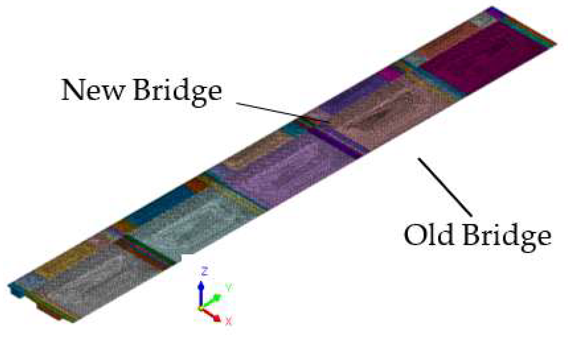
Based on the bridge design drawings, solid finite element models corresponding to the traditional splicing structure and the new slide-type transverse splicing structure are constructed, as depicted in Fig. 4. The concrete in the models is simulated using eight-node hexahedral solid elements, while the prestressing steel is represented by one-dimensional line elements. The transverse splicing between the flange plates of the old and new bridges will be modeled using the traditional articulated structure and the new slide-type transverse splicing structure, resulting in two distinct finite element models named the traditional splicing model and the new splicing model, respectively.
Figure 4.
Schematic cross-section of the overall finite ele ment model of the whole bridge.
The overall coordinate system of the model is defined with the endpoint of the inner flange plate of the old bridge at the starting section of the continuous beam as the coordinate origin. The orientation is set as follows:
- The Y-axis aligns with the longitudinal direction of the bridge, with positive direction from the small pile number to the big pile number.
- The X-axis corresponds to the transverse direction of the bridge, with positive direction extending from the splicing joints towards the old bridge direction.
- The Z-axis represents the vertical direction, with positive direction pointing upwards.
Both the old and new bridges have identical bearing constraints. All lateral restraints of the bearings, except for the fixed bearings, are released for both the old and new bridges.
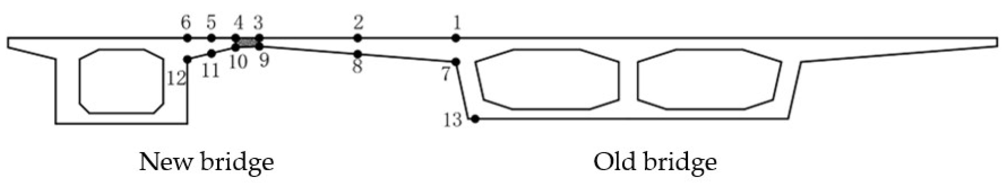
For the subsequent analysis and narrative, 11 control sections were selected along the longitudinal direction of both the old and new bridges, as depicted in Fig. 5. Each control section is labeled with thirteen stress control points, as illustrated in Fig. 6.
Figure 5.
Schematic diagram of control cross-section division.
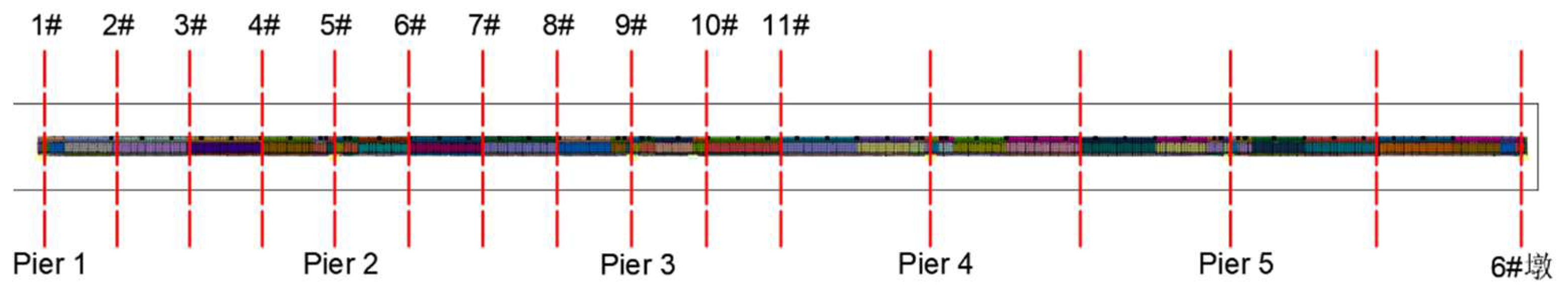
Figure 6.
Schematic diagram of cross-section control points.
3.2. Analysis of the Effect of Force Characteristics of Widened Structures Under Combined Operating Conditions
3.2.1. Define Combined Operating Conditions
The model simulates the entire process from the completion of the old and new bridges, through splicing and widening, to operational use, following the actual construction sequence. This process is divided into six analysis conditions, as shown in Table 1 below.
The load combination corresponding to Case 6 includes self-weight, prestressing, shrinkage creep, foundation settlement difference, and lane loading. This section focuses on analyzing the structural response of the widened bridges under this specific load combination. The load combinations will be determined in accordance with the relevant provisions for the serviceability limit state specified in the "General Specification for the Design of Highway Bridges and Culverts"( CCCC Highway Consultants Co., Ltd., 2015).
The wheel loads after widening are arranged according to the more unfavorable lateral bias load of the five-lane old bridge, as illustrated in Figure 7 below. Regarding the foundation settlement difference, this study considers an overall settlement of all foundations of the new bridge by 5mm.
3.2.2. Analysis of Lateral Displacement of Widening Structures
Figure 8 and Figure 9 illustrate the schematic diagrams of the lateral deformations of the widened bridge for Case 6 under the two splice widening methods. As shown in the figures, the maximum transverse displacement for both splicing schemes occurs at the girder end section.
Figure 10 plots the transverse displacement curves of each cross-section along the longitudinal direction of the bridge under the effect of concrete shrinkage creep differential. The data in the figure are taken from the transverse displacement value at control point 13#, located at the bottom of the main girder of the old bridge.
Analyzing Figure 10, the following observations can be made:
- (1)
- During three years after widening, the trend of transverse displacement along the longitudinal direction for both splicing methods due to the effect of shrinkage creep differential between the old and new bridges is essentially the same. The transverse displacement in the middle part of the bridge is nearly zero, but it increases as it approaches the girder ends.
- (2)
- The maximum transverse displacement at the end of the widened bridge with the traditional articulated splicing structure is about 40.8 mm. In contrast, the maximum transverse displacement at the end corresponding to the slide-type splicing structure is only about 6 mm, which is less than 1/7 of that observed with the traditional splicing structure. This demonstrates that the slide-type splicing structure can significantly mitigate the effect of shrinkage creep differential between two bridges on the widened bridge structure.
3.2.3. Transverse Stress Analysis of Widened Bridge
Based on the analysis results from section 3.2.2, it is evident that the transverse displacement change across the side span sections before and after widening is most pronounced. Therefore, this paper presents stress distribution variations of the inner flange plates at control points within sections 1#, 3#, and 5# of the widened bridge, aiming to compare the influence patterns of different transverse splice methods on transverse stresses at key control points, as shown in Figure 11, Figure 12 and Figure 13. In these figures, stress data represents tensile stress with positive values and compressive stress with negative values.
Analysis of the transverse stress variation curves in the figures reveals the following:
(1) When using the traditional hinge joint splice method, three years later, the transverse stresses at various control points of the inner splice flange plates increased to varying degrees compared to before widening. In contrast, when using the sliding joint splice structure, the increase is relatively small, and even the transverse stresses at various control points of the old bridge's inner splice flange plates have decreased.
(2) When using the traditional hinge joint splice method, the adverse effects of widening on the stress state of the inner splice flange plates are most significant at the beam end (section 1#) and section 5#. For example, at section 1# near the beam end, the transverse tensile stresses of the splice flange plates are significant, with the maximum tensile stress reaching 6.98 MPa. Similarly, at section 5# near the old bridge's inner support point, the upper flange points of the splice flange plates exhibit significant transverse tensile stresses, with a maximum value of 3.83 MPa. These maximum tensile stresses far exceed the standard tensile strength value of C50 grade concrete, which is 2.65 MPa, indicating a risk of extensive cracking in the inner flange plates of the old bridge from section 1# at the beam end to section 5# at the inner support point over a relatively long span. Effective reinforcement measures need to be proposed during the widening design process. In contrast, when using the sliding joint splice structure, only individual control points at section 1# of the splice flange plates near the beam end exhibit tensile stresses up to 3.14 MPa, but lower tensile stress values are observed in other longitudinal ranges of the splice flange plates, thereby eliminating the possibility of extensive cracking. Therefore, compared to the traditional splice structure, the sliding joint splice structure demonstrates significant advantages in crack resistance.
4. Mechanism of Force Transfer and Detailed Analysis of Transverse Spliced Structures
Due to the numerous components within the new splicing structure, such as square steel tubes, U-shaped rebar, and embedded rebar, it is impossible to perform a detailed analysis of the key force characteristics of each component within the overall finite element model. To study the transverse force transfer mechanism of the new splicing structure and improve analysis accuracy, this section will first establish a refined model of the bridge widening segment. Then, using the differential settlement between the foundations of the new and old bridges as an example, it will examine the mechanical characteristics of the transverse splicing box girder flange and the components of the splicing structure under the same load and boundary conditions, thereby obtaining the transverse force transfer mechanism of the widening structure.
4.1. Finite Element Modeling and Loading Conditions
According to the analysis in section 3.2, it is evident that the bridge end of the new and old box girders is the most critical part in terms of integrated stress. Therefore, in this section, a longitudinal segment with a length of 9.0 meters near the girder end cross-section is selected from the entire bridge model to establish a local refinement model, as shown in Fig. 14. The mesh size of the local model is 25 mm. The new and old box girders are simulated using eight-node hexahedral solid elements for concrete and embedded reinforcement, U-shaped reinforcement, square steel pipes, polyformaldehyde plates, and steel plates. The boundary conditions are modeled with articulation at the bottom four corners of the box girders. A forced displacement of 5 mm downward is applied to all the bearings of the new bridge to simulate the settlement of the new bridge foundation. Therefore, the working condition loads include self-weight, lateral prestressing, and vertical forced displacement.
4.2. Vertical Deformation Analysis
4.2.1. Differential Settlement between the Foundations of the New and Old Bridges
The displacement deformation of the new and old bridges during foundation settlement of the new bridge is shown in Figure 15. From the figure, the following conclusions can be drawn:
(1)Under the 5 mm differential settlement between the new and old bridges, the deformation is primarily borne by the spliced flange plate of the old bridge's box girder. Due to the shorter cantilever length and higher structural rigidity of the new bridge's box girder flange plate, it undergoes minimal flexural deformation. Consequently, the 5 mm settlement difference mainly results in significant bending deformation of the old bridge's box girder flange plate. There is a substantial change in vertical displacement from the end s to the middle of old bridge flange plate.
(2)The deformation transition between the flange plates of two box girders exhibits a relatively smooth behavior. The deflection difference at the splicing joint, measured between the two ends of the flange plates, is merely 0.052 mm, without any abrupt changes in displacement. These findings suggest that the splicing structure effectively transfers foundation settlement from the new bridge to the old bridge's flange, thereby demonstrating its capability to efficiently coordinate vertical deformation differences.
4.2.2. Shear Force Transfer Mechanism in Slideway-Spliced Structures.
As the embedded steel bars and U-shaped steel bars are arranged at intervals, the cross-sections of the widened bridge’s transverse splice joints are categorized into two types based on the presence or absence of these reinforcements: A-section with transverse reinforcement and B-section without transverse reinforcement. To comprehend the vertical load transfer mechanism in slideway-spliced structures, this paper takes the transmission process of new bridge foundation settlement deformation as an example. By analyzing the deformation of each component within the spliced structure, this study aims to explore how the vertical load is transferred from one side of the transverse splice joint to the other. Figure 16 illustrates the schematic diagrams of vertical deformation transfer processes for each component of the spliced structure in local models A and B sections, respectively.
The analysis of Figure 16 reveals the following:
(1) The position of the new and old bridges in the figure shows that the flange plate of the new bridge box girder is on the left side of the transverse splicing seam. Under the settlement of the new bridge foundation, the square steel tube will undergo obvious counterclockwise torsional deformation, consequently, other components will also undergo corresponding structural deformation. A careful analysis of the torsional deformation of the square steel tube reveals four contact deformations between the square steel tube and the surrounding components, namely, extrusion deformation in areas A, B, and C, and welding contact in area F.
(2) Due to the presence of embedded steel bars and U-shaped steel bars in section A, extrusion will occur between the head of the embedded steel bars and the square steel tube in area A of the splicing structure, thereby transferring part of the vertical shear force; at the same time, extrusion will occur between the square steel tube and the polyformaldehyde plate at B and C, and the pressure borne by the polyformaldehyde plate will be transferred to the upper and lower concrete of the square steel tube. Therefore, through the extrusion at A, B, and C, the downward shear force borne by the structure on the left side of the transverse splicing seam is smoothly transferred to the square steel tube. There are no embedded steel bars and U-shaped steel bars in section B, and extrusion will occur between the square steel tube and the polyformaldehyde plate in areas C and B of the splicing structure of this section, but the corresponding transmission of vertical shear force is secondary.
(3) When the square steel tube is subjected to the downward shear force, as shown in Figure 16(a), the vertical shear force on the left side of the transverse splicing seam is transferred to the right side by means of the welding force between the back of the square steel tube and the U-shaped steel bar, and then the flange plate of the right old bridge box girder begins to bear part of the shear force. Based on the above channel, the vertical deformation acting on the left side of the transverse splicing seam is smoothly transferred to the right side.
It can be seen from the above analysis of the internal force transmission mechanism of the transverse splicing structure that the extrusion and welding contact between relevant components are the key channels for internal force transmission. Therefore, it is crucial to accurately analyze the stress changes in these areas and their impact on the surrounding concrete, which is of great significance for the operational safety of the splicing structure.
4.3. Stress Analysis
4.3.1. Contact Stresses on Splice Structures
The effect of 5 mm vertical settlement of the new bridge foundation on the vertical direction of the structure is significant, so the following section will mainly focus on the analysis of vertical contact stress. Figures 26~28 show the vertical contact stresses of square steel pipe, pre-embedded reinforcement and polyformaldehyde plate under the action of 5mm settlement of the new bridge foundation, respectively.
(1) The maximum vertical contact stress in area C of the square steel tube is 7.87 MPa, with higher stress concentrated at the welding location between the square steel tube and the U-shaped steel bar, particularly near the upper limb of the U-shaped steel bar.
(2) The extrusion stress in area A between the end of the embedded steel bar and the square steel tube mainly varies within the range of 0-13.67 MPa, with a maximum extrusion stress of 163.99 MPa in some areas, indicating severe extrusion in these locations.
(3) Observing the contact stress contour plot of the polyformaldehyde plate, it can be found that its stress characteristics are consistent with the vertical deformation of the splicing structure in Section 3.1.2. The stress concentration is evident in areas B and C, with a maximum extrusion stress of 4.39 MPa in both areas.
Stress in the Inner Flange of New Bridge
Figure 20 illustrates the vertical stress distribution in the concrete at the end of the new bridge’s inner flange slab. As depicted, stress concentrations are evident in the concrete above and below the square steel tube due to extrusion. These locations align with the areas of high extrusion stress observed in the polyformaldehyde plate (areas B and C), as discussed in Section 3.3.1. However, both areas B and C exhibit relatively small principal tensile stresses in the concrete. The areas of higher principal tensile stress are primarily located near the concrete at the ends of the pre-embedded reinforcement, particularly above the ends, reaching a maximum of 11.36 MPa. This significant stress level suggests potential cracking in these concrete regions, warranting attention and further investigation.
Stress in the Inner Flange of Old Bridge
The Figure 21 reveals two distinct areas of high stress:
1# Area: This area, situated within the transverse prestressing tendon anchorage zone, exhibits stress concentration as a direct result of prestressing tension.
2# Area: Located near the end of the U-bar within the old bridge’s flange plate, this area experiences stresses ranging from 2 to 4 MPa, potentially leading to concrete cracking. This stress concentration is likely attributed to the settlement of the new bridge. As the new bridge settles, the pre-embedded reinforcement at its edge pushes downward on the square steel pipe, causing downward displacement of both the pipe and the old bridge’s flange end. This downward force is then transferred from the square steel pipe to the welded U-shaped steel bar, leading to its downward displacement and subsequent extrusion of the concrete near the U-bar’s end, ultimately resulting in the observed stress concentration.
In summary, under the influence of foundation settlement, significant stress concentrations are observed in the concrete near the ends of the U-bars on the old bridge side and the pre-embedded reinforcement bars on the new bridge side. These areas require attention and could benefit from reinforcement measures such as the installation of steel mesh or FRP cloth.
Furthermore, when the new bridge foundation settles by 5mm, with the exception of the concrete at the U-bar and pre-embedded reinforcement locations, the concrete surrounding the square steel pipe notch does not exhibit significant transverse or vertical stress concentrations. This indicates that the differential vertical deformation caused by the new bridge foundation settlement is primarily accommodated by the pre-embedded reinforcement in the new bridge’s flange plate and the concrete near the extruded ends of the U-bars in the old bridge’s flange plate.
5. Analysis of Design Parameters for Slide-Type Lateral Connection Structures
The previous analysis was conducted for a specific size and ideal construction scenario of the slide-type splicing structure. Since the vertical stiffness of the square steel tubes in the splicing structure significantly affects the structural forces, it is necessary to analyze the force performance of this new structure with square steel tubes of different thicknesses.
5.1. Calculation Description
In this section, three solid models are established with square steel tube thicknesses of 5mm, 10mm, and 15mm, respectively, based on the localized refined model from Section 3.1, as shown in Figure 22. The structural performance of these three splicing structures under combined working conditions is analyzed. These scenarios are referred to as Condition 1, Condition 2, and Condition 3, respectively.
5.2. Stress State Under Combined Conditions
Based on the analysis in Section 3.2, the mechanical response indicators that should be focused on under combined conditions for the widened structure are: Principal tensile stress in the concrete at the ends of the inner flange plates of the new and old bridges, Weld contact stress at the welded joints between U-shaped steel bars and square steel tubes, Compressive contact stress between the embedded steel bar ends and the square steel tubes. The calculation results for the three conditions are shown in Table 2. The stress values for the concrete at the ends of the inner flange plates of the new and old bridges (indicator 1) are taken from regions B and C in Figure 16 of Section 4.2.2.
The analysis of the mechanical response indicators in the chart reveals that, with the increase of the square steel tube thickness, under otherwise identical conditions:
- Both the principal stress of concrete at the inner flange plate ends of the new and old bridges (taking regions B and C as examples) and the maximum contact stress at the weld significantly increase.
- The maximum extrusion contact stress between the end of the embedded rebar and the square steel tube decreases significantly.
It is suggested that an increase in the wall thickness of the square steel tube leads to an increase in its vertical stiffness. Under vertical actions such as the differential settlement of the new and old bridge foundations and vehicle loads, the counterclockwise torsional deformation of the square steel tube is reduced, and its ability to absorb the vertical displacement difference on both sides of the joint through its own deformation is weakened, resulting in a more severe extrusion on the upper and lower polyformaldehyde plates and concrete.
When the wall thickness of the square steel tube increases from 5mm to 10mm and 15mm, the risk of concrete cracking in regions B and C increases. Based on the axial tensile strength of C50 concrete (2.65MPa), it is recommended to control the wall thickness of the square steel tube within 5mm. From the perspective of the maximum extrusion stress between the transverse connecting rebar and the square steel tube, the increase in the wall thickness of the square steel tube significantly improves its torsional stiffness, leading to a rapid decrease in the extrusion stress between the two.
This indicates a change in the transverse force transfer mechanism. The transverse shear force is mainly transferred through the extrusion between the square steel tube wall and the surrounding concrete, which may lead to an increase in the principal tensile stress of the surrounding concrete and cracking. In conclusion, it is recommended that the wall thickness of the square steel tube be 5mm.
6. Conclusions
(1) The novel slide-type transverse splicing structure effectively absorbs the differential longitudinal shrinkage and creep deformation between the new and old bridges, making it suitable for widening multi-span continuous concrete box girder bridges. Compared to traditional splicing methods, which can lead to structural defects, this innovative approach proves advantageous. Take the bridge in this study as an example: using a traditional hinged connection for widening resulted in a maximum transverse deformation of 40mm at the beam end after three years, potentially causing damage to the seismic stoppers due to lateral extrusion of the web. However, the slide-type splicing structure limited the maximum deformation to approximately 6mm, effectively accommodating the differential shrinkage and creep between the new and old bridges.
(2) Under comprehensive load conditions, adopting the traditional hinged connection leads to a maximum transverse stress of 6.98MPa at the flange edge of the box girder, posing a significant cracking risk to the area surrounding the splice and the inner flange of the old bridge. Conversely, the slide-type splicing structure significantly reduces tensile stress in these areas, effectively preventing cracks. However, this innovative method exhibits higher welding stress between the U-shaped steel and the square steel tube near the support section, requiring attention and potential mitigation strategies, such as increasing the density of U-shaped steel.
(3) Under differential foundation settlement and traffic loads, the transverse transmission of vertical shear force in the splicing structure is primarily achieved through the coordinated deformation and stress distribution among the embedded steel bars, square steel tubes, and U-shaped steel. Research indicates that extrusion occurs between the head of the embedded steel bar and the square steel tube at the cross-section, contributing to vertical shear force transfer. Simultaneously, the square steel tube experiences extrusion against the upper and lower polyformaldehyde plates, which then transfer the pressure to the concrete above and below.
(4) The thickness of the square steel tube significantly influences the stress distribution within the widened structure. Excessive thickness intensifies the extrusion exerted by the square steel tube on the upper and lower polyformaldehyde plates and concrete. Increasing the thickness to 10mm or 15mm even risks widespread cracking in the concrete at the inner flange ends of both bridges. Therefore, a wall thickness of 5mm is recommended as the most reasonable value, effectively balancing structural integrity and performance.
Acknowledgments
The paper is founded by National Nature Science Funding of China (Grants number: 52278149).
References
- CCCC Highway Consultants Co., Ltd. (2015). JTG D60-2015 General code for design of highway bridges and culverts [In Chinese]. China Communications Press.
- Chen, K.M., Wu, Q.X., Chen, B.C., & Zhang, G. (2016). Method and Tests for Partially Splicing and Widening Long-span Bridges. China Journal of Highway and Transport, 29(11), 99-107. (In Chinese).
- Cousins, D.P. (2017). Reinforced Concrete Beam Hinge Joint Fatigue Assessment. Bridge Engineering, 1–11.
- Elsafty, A., Okeil, A.M., Torres, K., Tawfiq, K., & Fallaha, S. (2020). Investigation of Empirical Deck Design in Bridge Widening. Journal of Bridge Engineering, 25(10), 04020079.
- Fang, Z., Chang, H.H., Yang, X.Q., & Yuan, Y. (2013). Lateral Effects Caused by Shrinkage and Creep in Widened and Spliced Concrete Box Girder Bridges. China Journal of Highway and Transport, 26(6), 65-72. (In Chinese).
- Guo, Q., Sun, Y., & Mi, T. (2021). Assessment on Long-term Deflection of Concrete Beam Bridges Based on Uncertainty Quantification Method. Structures, 34, 3013-3027.
- Hosseini, M., & Jefferson, A.D. (1998). Time-Dependent Behavior of Widened Reinforced Concrete Under-bridge. Materials and Structures, 31(10), 714-719.
- Joergensen, H.B., & Hoang, L.C. (2013). Tests and Limit Analysis of Loop Connections Between Precast Concrete Elements Loaded in Tension. Engineering Structures, 52, 558-569.
- Li, Z.F. (2019). Verification Method for Widening Long-Span Bridges Using Steel Plate Splicing at Both Ends. Fujian Traffic Technology, (1), 54-57. (In Chinese).
- Nie, J.G., Wang, Y.H., Zhang, X.G., & Fan, J.S., & Cai, C.S. (2012). Mechanical Behavior of Composite Joints for Connecting Existing Concrete Bridges and Steel–Concrete Composite Beams. Journal of Constructional Steel Research, 75, 11-20.
- Ru, Y. (2014). Research on Several Issues in the Widening Structure of In-service Concrete Box Girder Bridges. [PhD dissertation, Southeast University]. (In Chinese).
- Tu, B., Fang, Z., Dong, Y., et al. (2017). Time-Variant Reliability Analysis of Widened Deteriorating Prestressed Concrete Bridges Considering Shrinkage and Creep. Engineering Structures, 153, 1-16.
- Wen, Q.J. (2011).Long-term Effect Analysis of Prestressed Concrete Box-Girder Bridge Widening. Construction and Building Materials, 25(4), 1580-1586.
- Wen, Q.J., & Jing, H.W. (2014).Numerical Simulation of Creep and Shrinkage in Widened Concrete Bridges. Magazine of Concrete Research, 66, 661-673.
- Wu, W.Q, Zhang, H., Liu, Z., & Wang, Y. (2022).Numerical Analysis on Transverse Splicing Structure for the Widening of a Long Multi-Span Highway Concrete Continuous Box Girder Bridge. Materials, 15, 6805.
- Wu, W.Q., Shan, H., Yang, S., et al. (2017).Key Assumption to Evaluate the Mechanical Performance of Widened Voided-Slab Bridge Due to Foundation Settlement. KSCE Journal of Civil Engineering, 22(4), 1225-1234.
- Wu, W.Q., Tang, Z.X., Zhang, H., et al. (2018).Analysis of Deck Damage in Existing Prestressed Concrete Continuous Box Girder Bridges After Widening and Splicing. China Journal of Highway and Transport, 31(5), 63-73. (In Chinese).
- Wu, W.Q., et al. (2012).Comparison of Transverse Widened Structure of Wide-size Voided Slab Beam Bridge on Expressway. Journal of Highway and Transportation Research and Development, 29(3), 92-97, 117.
- Yan, G.B. (2013).Research on Influencing Factors and Countermeasures for Widening and Splicing Long-span Prestressed Concrete Continuous Box Girder Bridges. [Doctoral dissertation, China Academy of Railway Sciences]. (In Chinese).
- Yang, Y., Wu, E.J., Lan, W.J., & Wang, J.Y. (2013).Analysis of Solutions for Disengagement in Continuous Bridge Lifting and Reconstruction. Journal of Water Resources and Architectural Engineering, 11(6), 35-39. (In Chinese).
- Ye, Y.C., Li, S.Q., & Zhang, Y. (2013).Analysis and Countermeasures of Influencing Factors in Widening and Splicing Long-span Highway Bridges. Railway Engineering, (10), 24-27. (In Chinese).
- Zhou, J.Y., Li, T., Ye, X.J., et al. (2020).Safety Assessment of Widened Bridges Considering Uneven Multilane Traffic-Load Modeling: Case Study in China. Journal of Bridge Engineering, 25(9), 1-12.
Figure 1.
Cross-section of the existing bridge box girder (units: cm).
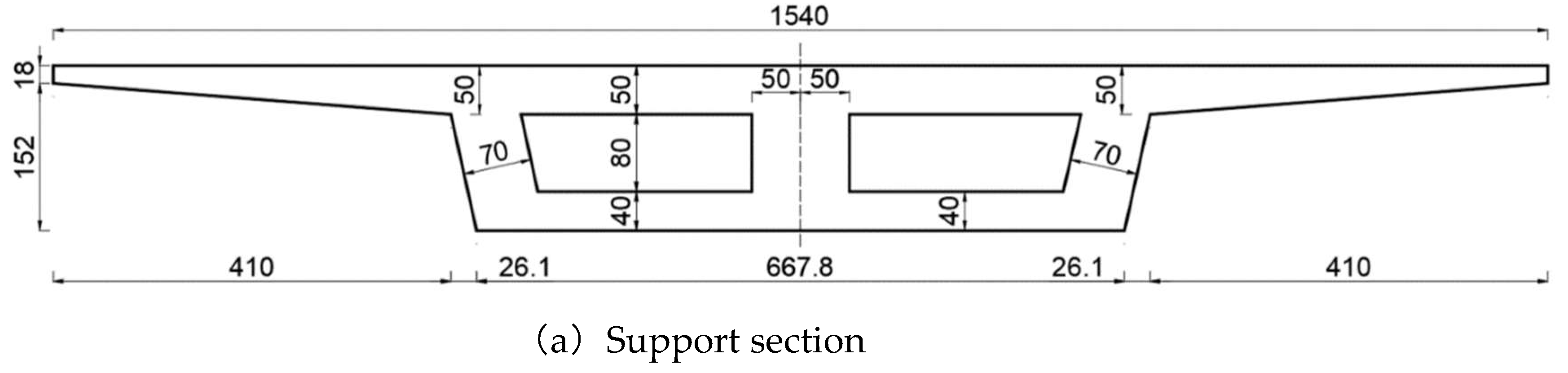
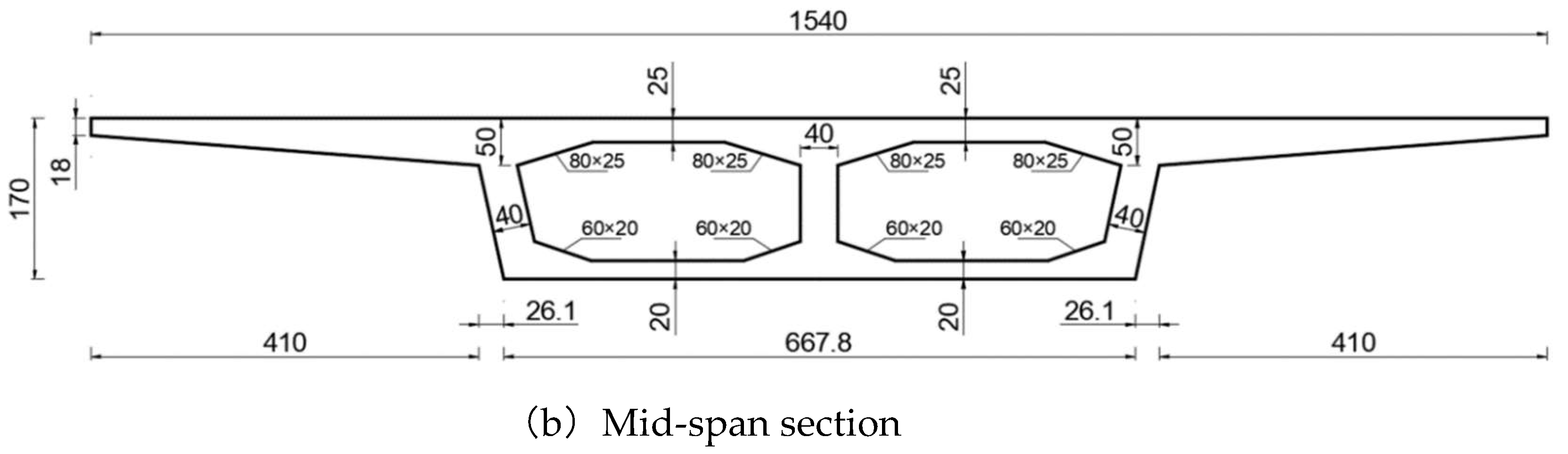
Figure 2.
Splicing schematic diagram (units: cm).
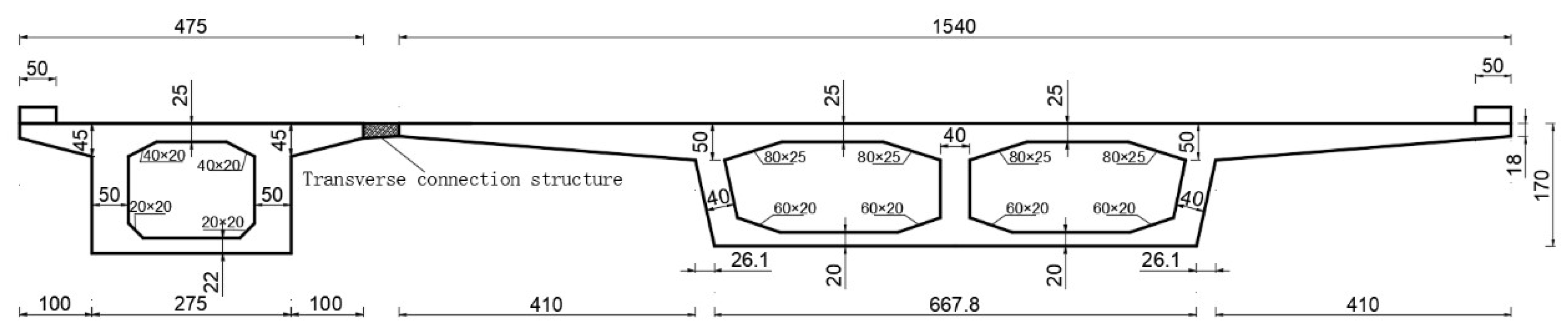
Figure 3.
Schematic diagram of the sliding-type lateral connection structure (units: cm).
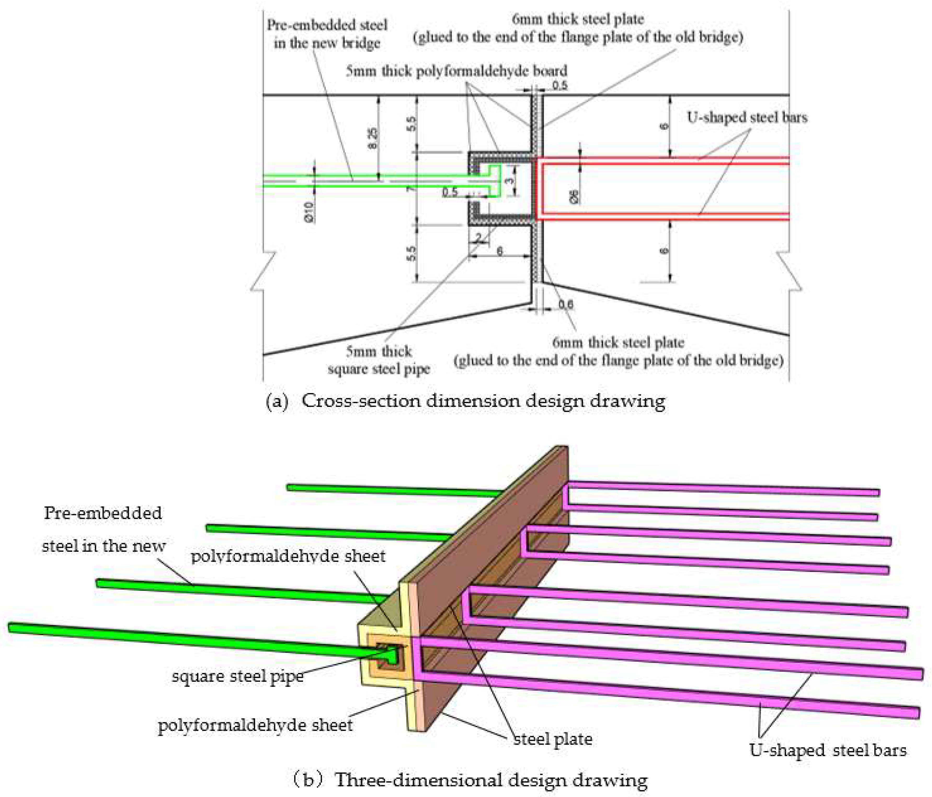
Figure 7.
Schematic diagram of lateral five-lane old bridge after widening.
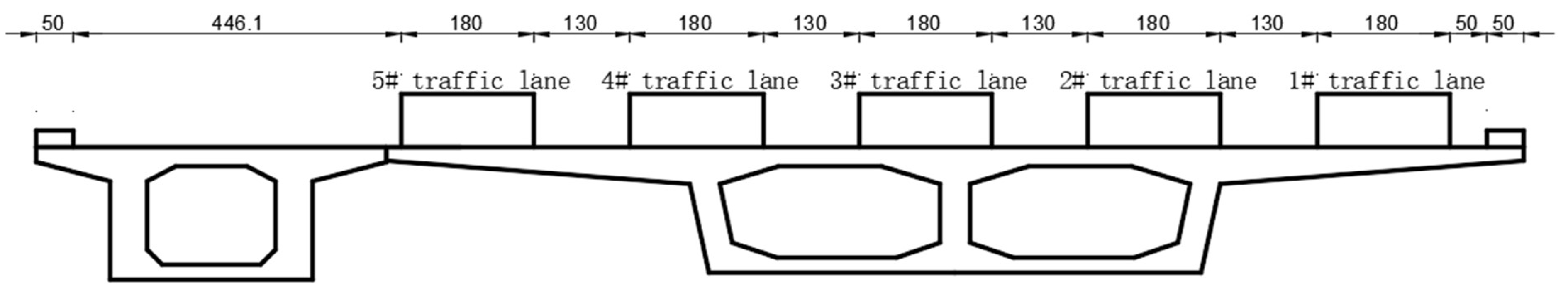
Figure 8.
S Schematic Diagram of Lateral Deformation for Traditional Hinged Widened Bridges (units: mm).
Figure 8.
S Schematic Diagram of Lateral Deformation for Traditional Hinged Widened Bridges (units: mm).
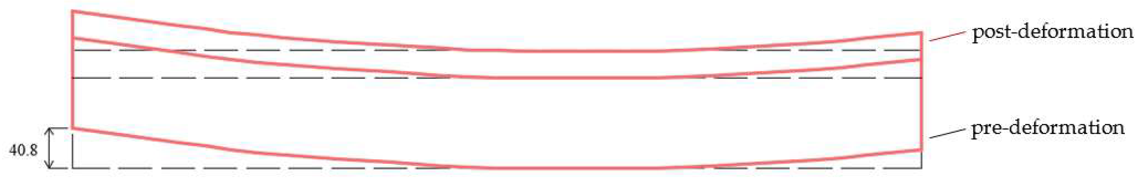
Figure 9.
Schematic Diagram of Lateral Deformation for Slide-Spliced Widened Bridges (units: mm).
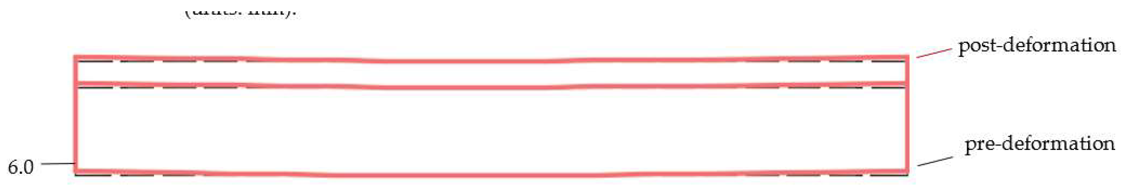
Figure 10.
Graph Showing the Relationship Between Lateral Splicing Methods and Lateral Deformation of Widened Bridges.
Figure 10.
Graph Showing the Relationship Between Lateral Splicing Methods and Lateral Deformation of Widened Bridges.
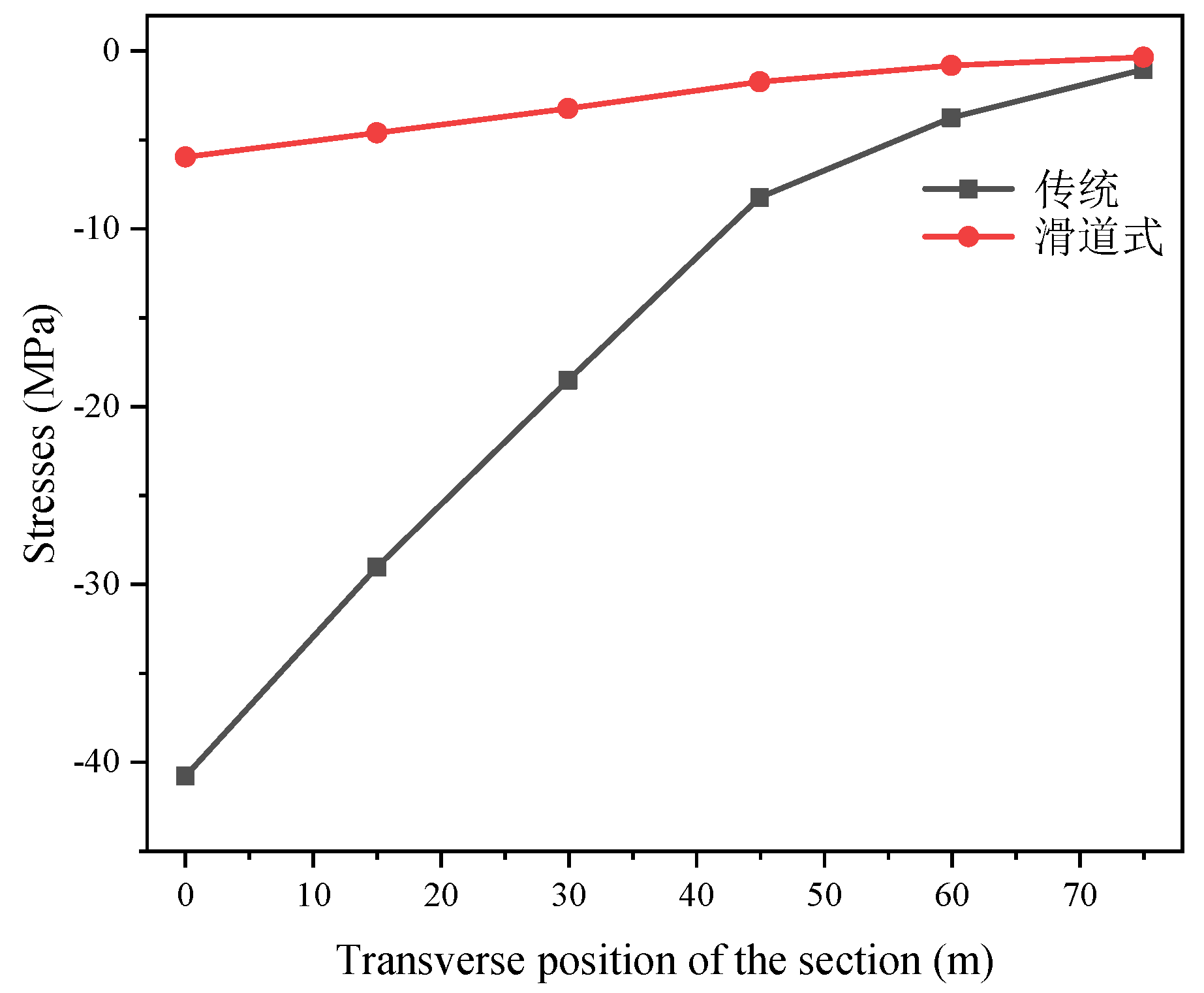
Figure 11.
Transverse stress variation curve of the inner flange plate at section 1#.
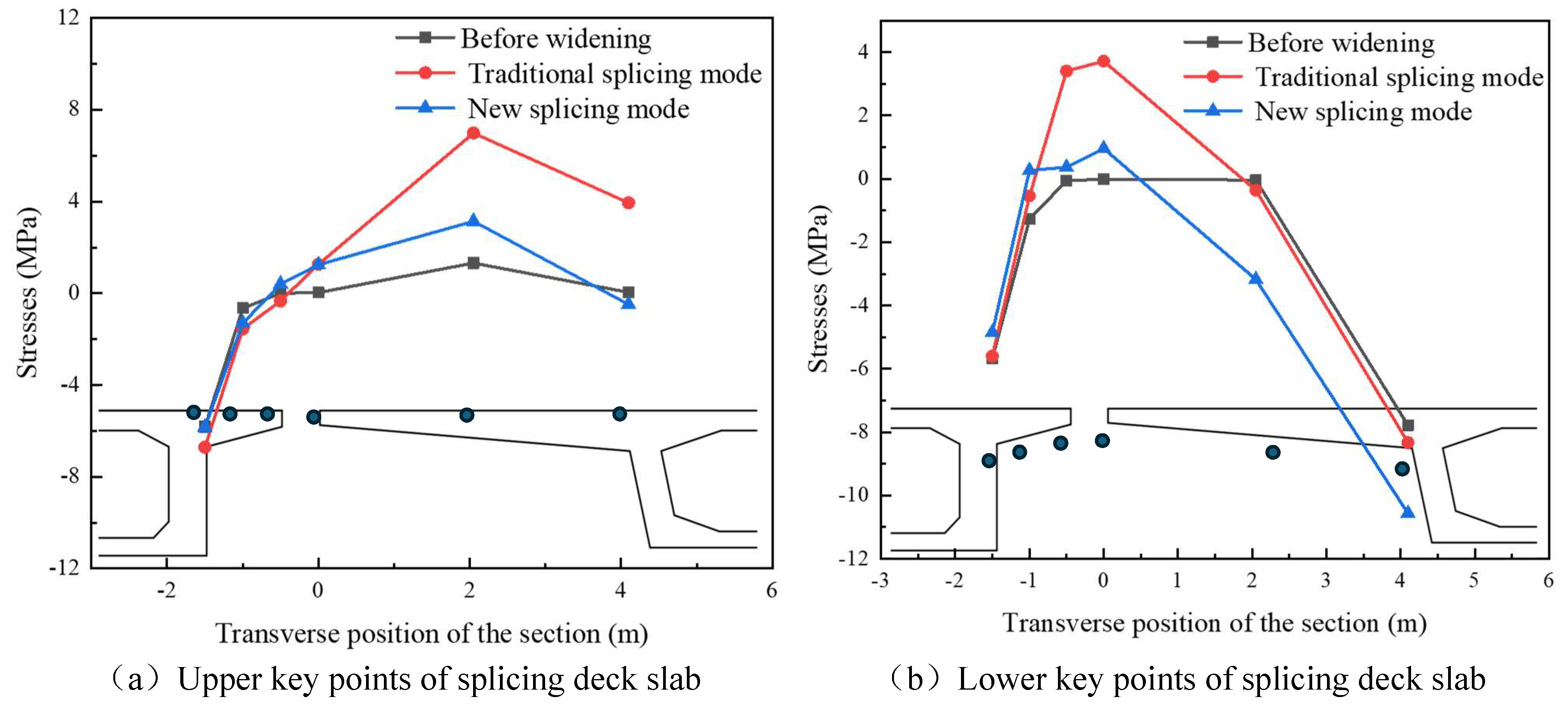
Figure 12.
Transverse stress variation curve of inner flange plate at section 3#.
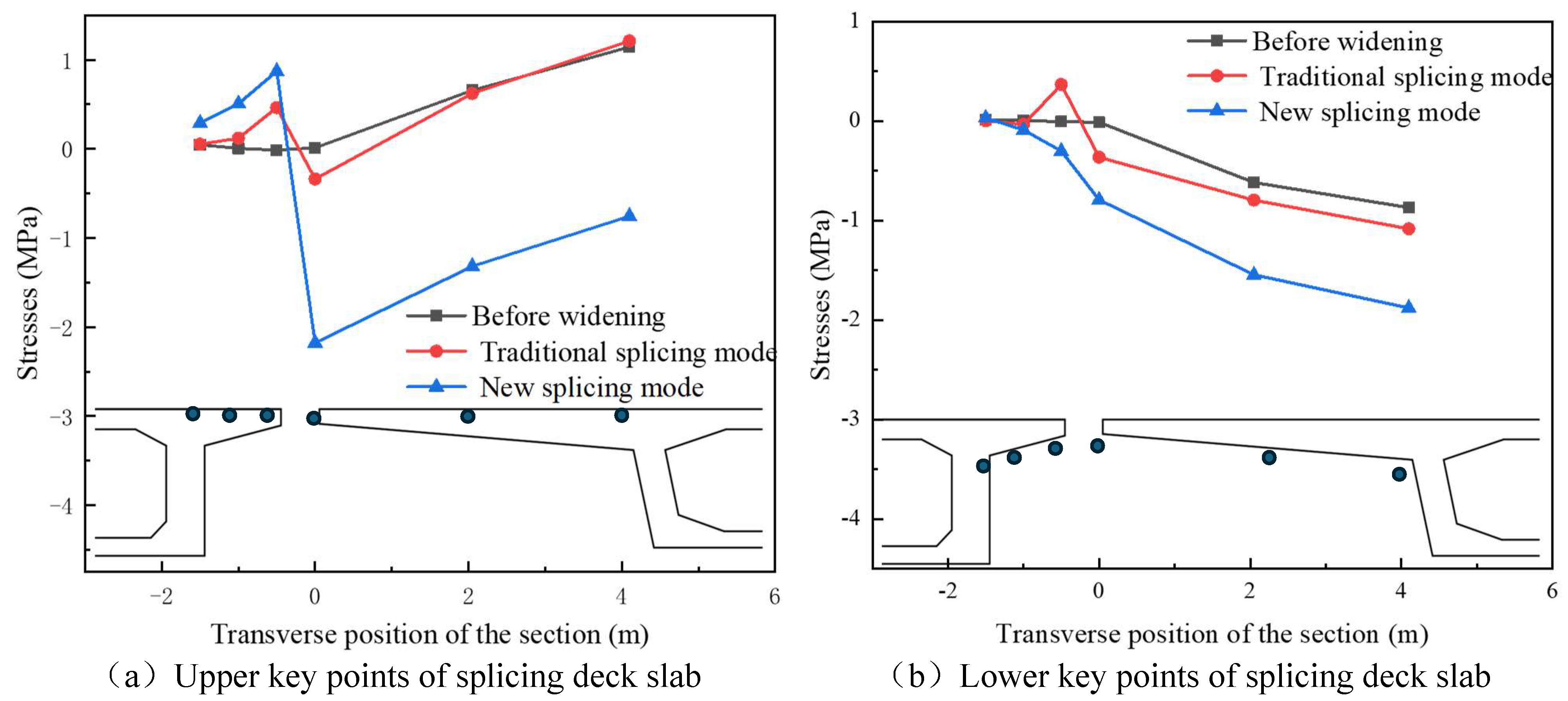
Figure 13.
Transverse stress variation curve of inner flange plate at section 5#.
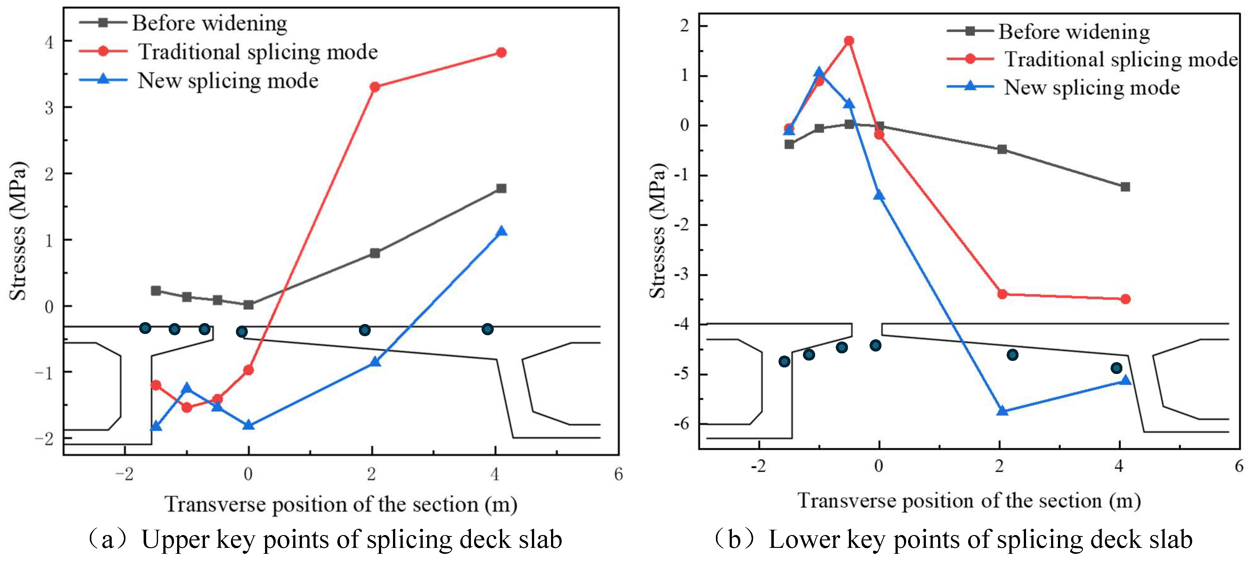
Figure 14.
Schematic diagram of the local model.
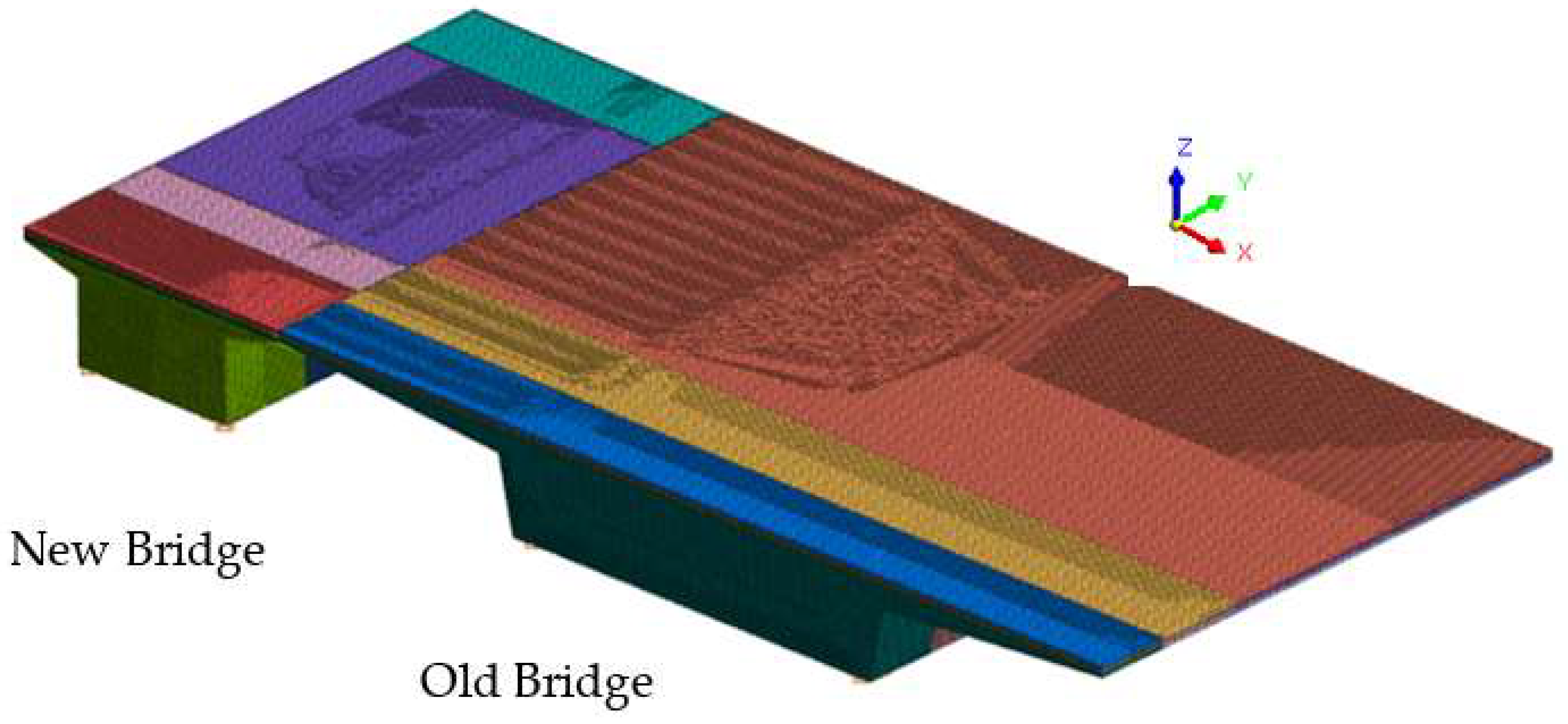
Figure 15.
Schematic representation of vertical displacement variation in a widened bridge due to differential foundation settlement.
Figure 15.
Schematic representation of vertical displacement variation in a widened bridge due to differential foundation settlement.
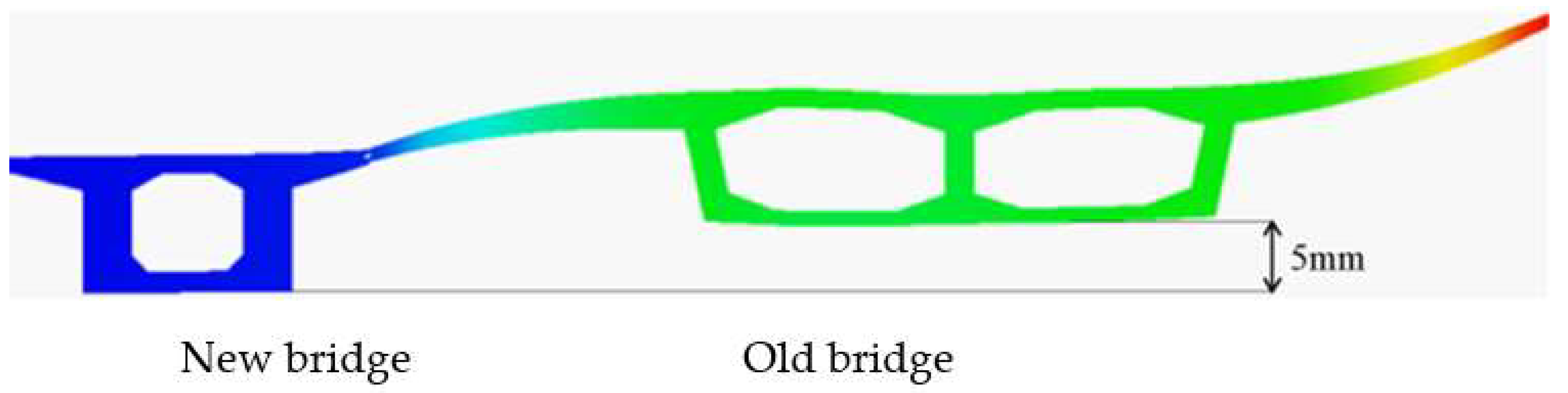
Figure 16.
Schematic diagram of deformation of each component in spliced structure under new bridge settlement.
Figure 16.
Schematic diagram of deformation of each component in spliced structure under new bridge settlement.
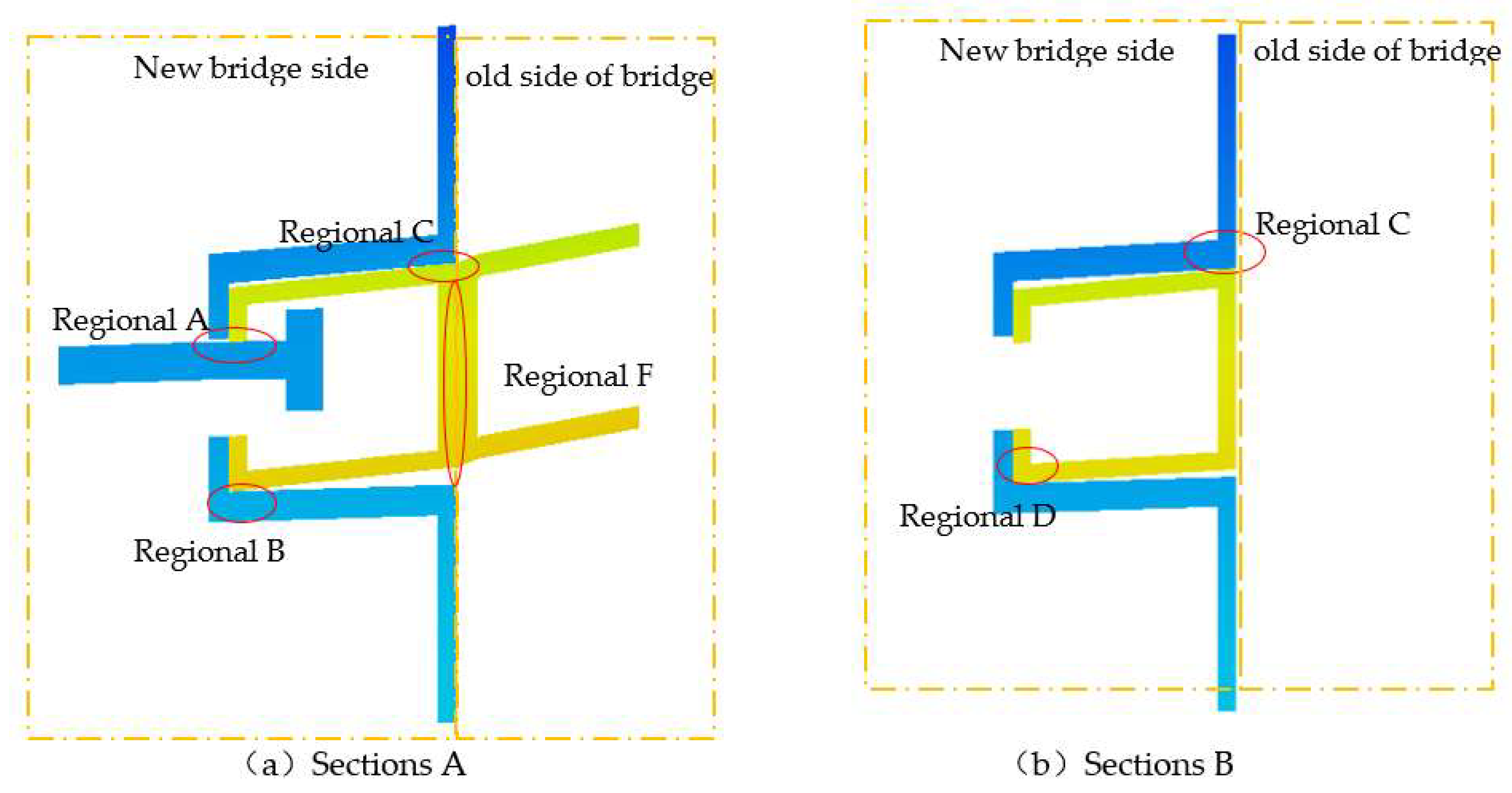
Figure 17.
Contact stress cloud of square steel pipe.
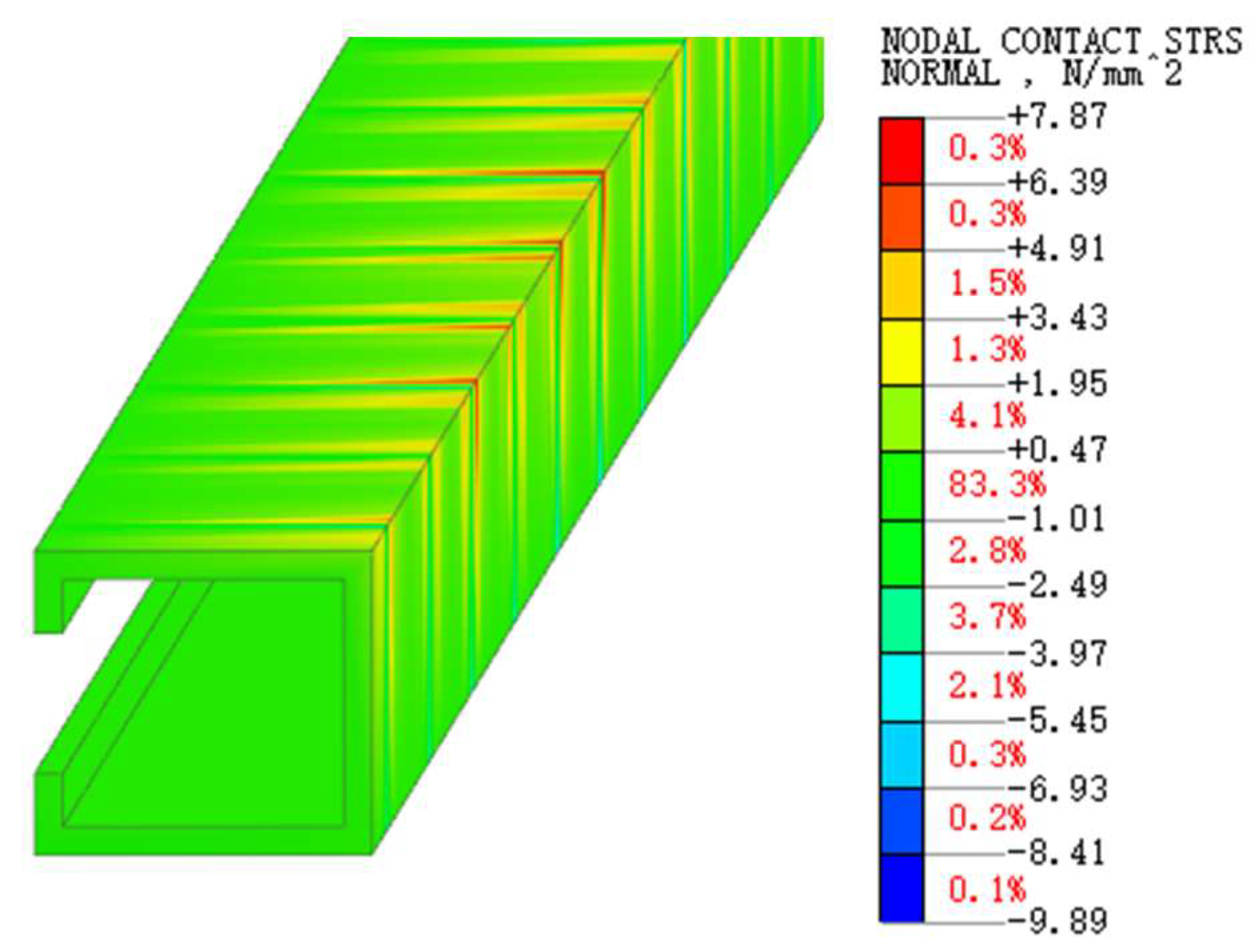
Figure 18.
Cloud of contact stresses at the end of pre-embedded reinforcement.
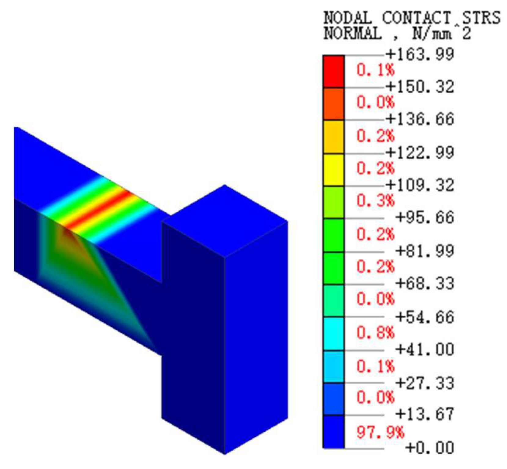
Figure 19.
Contact stress cloud of paraformaldehyde plate4.3.2. Main Girder Concrete Stress.
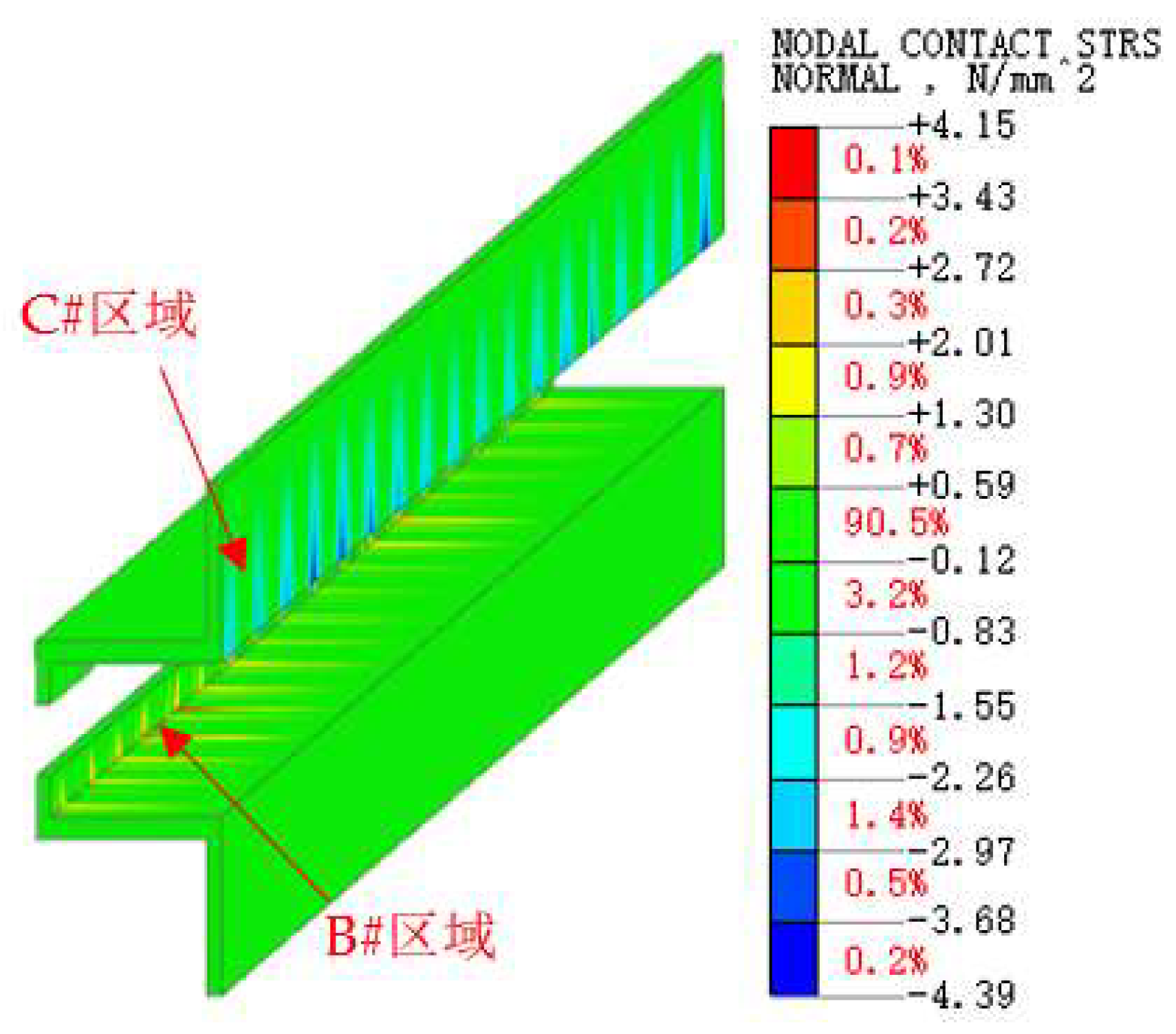
Figure 20.
Vertical stress cloud at the end of the inner flange plate of the new bridge.
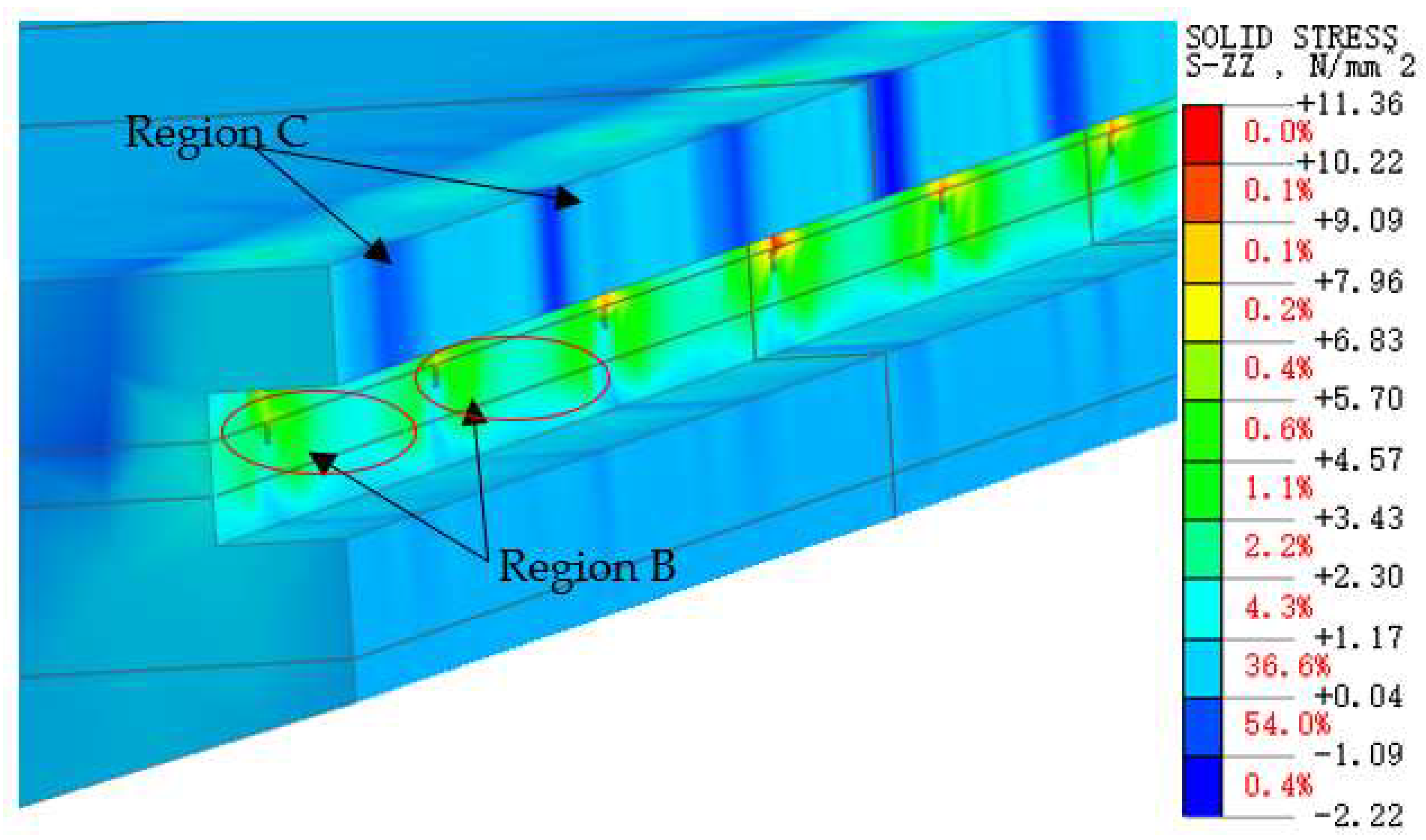
Figure 21.
Vertical stress cloud at the end of the inner flange plate of the old bridge.
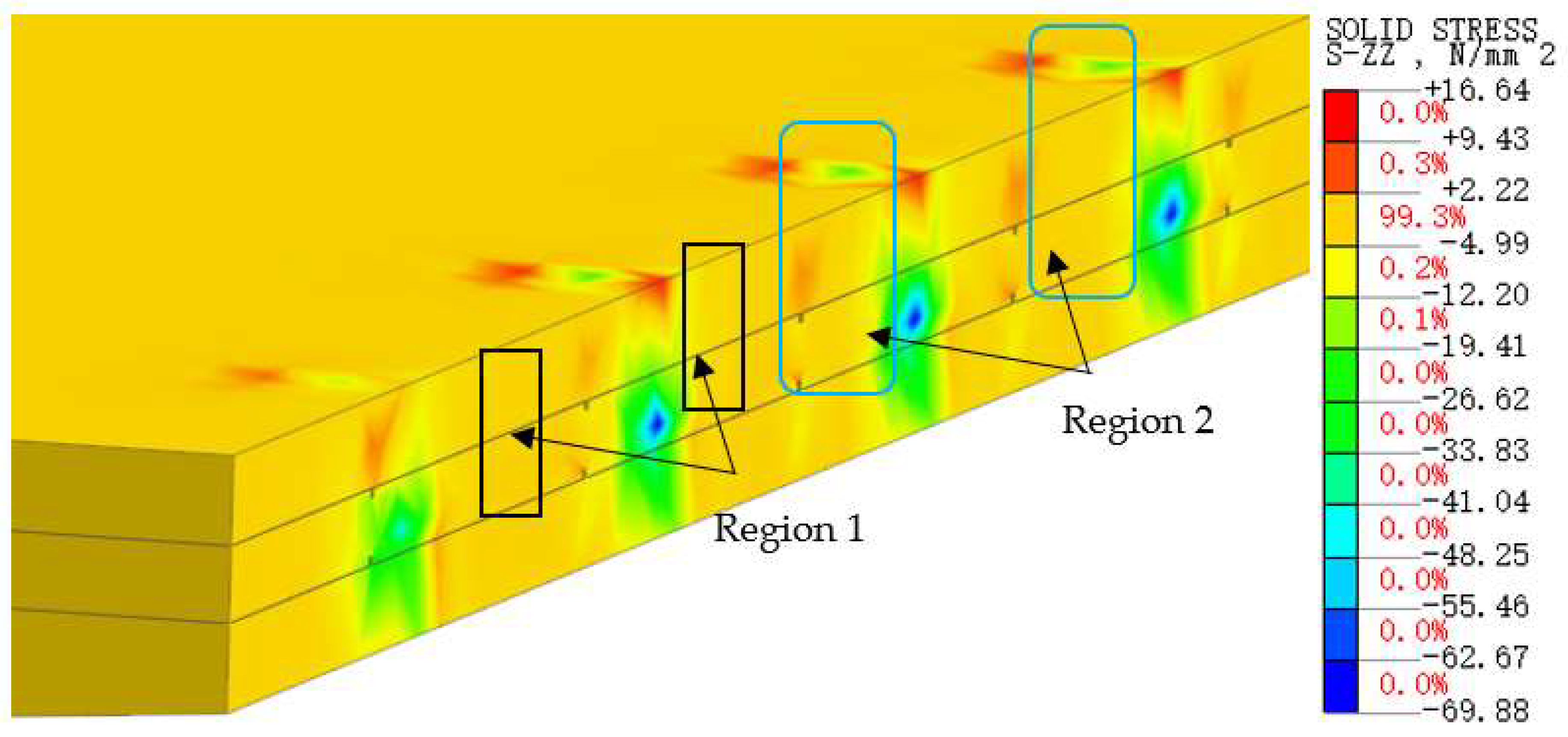
Figure 22.
Schematic Diagram of Solid Models with Different Square Steel Tube Thicknesses. (a) Condition 1: 5mm Thick Square Steel Tube (b) Condition 2: 10mm Thick Square Steel Tube (c) Condition 3: 15mm Thick Square Steel Tube.
Figure 22.
Schematic Diagram of Solid Models with Different Square Steel Tube Thicknesses. (a) Condition 1: 5mm Thick Square Steel Tube (b) Condition 2: 10mm Thick Square Steel Tube (c) Condition 3: 15mm Thick Square Steel Tube.
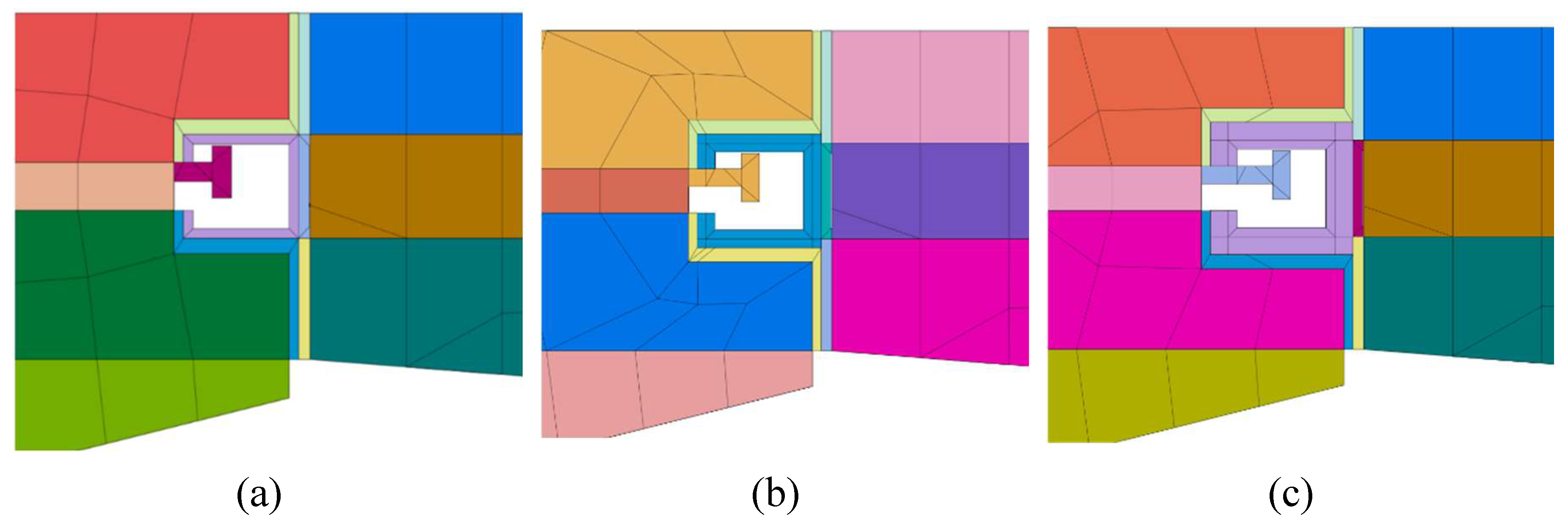

Table 1.
Model analysis conditions.
| No | construction phase |
| 1 | Completion of the old bridge |
| 2 | old bridge in operation for ten years |
| 3 | New bridge built |
| 4 | Six months after new bridge built |
| 5 | Completion of bridge widening |
| 6 | Operation together for 3 years |
Table 2.
Variation of Mechanical Response Indicators with Square Steel Tube Thickness.
| Mechanical Response Indicators | Square Steel Tube Thickness (mm) | |||
| 5 | 10 | 15 | ||
| Principal tensile stress in the concrete at the ends of the inner flange plates of the new and old bridges (MPa) | Region B | 1.33 | 1.87 | 2.49 |
| Region C | 2.41 | 2.89 | 3.50 | |
| Maximum compressive contact stress between the embedded steel bar ends and the square steel tubes (MPa) | 163.99 | 0.15 | 0 | |
| Maximum weld contact stress at the welded joints (MPa) | 125.70 | 129.73 | 142.05 | |
Disclaimer/Publisher’s Note: The statements, opinions and data contained in all publications are solely those of the individual author(s) and contributor(s) and not of MDPI and/or the editor(s). MDPI and/or the editor(s) disclaim responsibility for any injury to people or property resulting from any ideas, methods, instructions or products referred to in the content. |
© 2024 by the authors. Licensee MDPI, Basel, Switzerland. This article is an open access article distributed under the terms and conditions of the Creative Commons Attribution (CC BY) license (http://creativecommons.org/licenses/by/4.0/).
Copyright: This open access article is published under a Creative Commons CC BY 4.0 license, which permit the free download, distribution, and reuse, provided that the author and preprint are cited in any reuse.


