Submitted:
29 October 2024
Posted:
31 October 2024
You are already at the latest version
Abstract
Presented study demonstrates the application of actual technologies and tools for the development of a large scale axial flux electricity generator. (1) Background: The specifics of its application – run-of-river site – predefine design requirements, close to wind turbine generator. An extensive study of available solutions is used as a start point for further concept development; (2) Methods: A step based methodology is defined for concept parameters assessment and feasibility study. It demonstrates the advantages of virtual prototyping when assessing various design parameters; (3) Results: Several simulations over built different virtual prototypes provide sufficient information to elaborate an improved design concept. Major result is a ready for detailed design concept, with defined major parameters and studied work behavior; (4) Conclusions: The major outcome is the presentation of the application of virtual prototyping in assessment of large structures, where physical prototyping is expensive and time consuming approach. Application of virtual prototyping at very early product development stage is an effective way to undertake efficient solutions towards the concept of the product.
Keywords:
AFPM
; electricity generator
; large scale structure
; virtual prototyping
; electromagnetics
; hydrokinetic power system
1. Introduction
The demand of energy and electricity is rising at its fastest rate in the last years, driven by growing population, robust economic growth, intense heatwaves and increasing uptake of technologies that run on electricity. The strong increase in global electricity consumption is set to continue into next years, with growth around 4%, according to the report of the International Energy Agency (IEA) [1]. Two major challenges, related to energy demand increase, could be fixed: equal energy access to all countries and people, and the need of reduction of greenhouse gas emission and environmental pollution [2]. It is known that the renewable energy will play a key role in decarbonizing energy systems in the coming decades. Currently the most popular energy sources are: solar, wind, hydro, geothermal and biomass energy. As a renewable energy resource, hydro power is one of the most commercially developed. Hydropower plants are currently the most contributory renewable energy source worldwide, and they continue to be installed, especially in emerging countries [3], [4]. Hydro power generation could be divided in next major types: storage (and its variant – pumped storage), run-of-river (including in-stream) and tidal. Run-of-river hydropower plant draws the energy for electricity production mainly from the available flow of the river (sometimes called “zero-head” hydropower), sometimes with short-time storages [5]. In-stream solutions are a good alternative, having lower environmental impact, in high flow rivers by using their high kinetic energy. Generally, hydrokinetic systems convert the energy of moving water in rivers, oceans, or tidal currents into electricity without the use of a dam or barrage associated to conventional hydropower [6]. There are several kinds of hydrokinetic turbines of various sizes and different energy capture principles. The major classification of hydrokinetic turbines is related to the rotating axis positions with respect to the water flow: with horizontal axis and with vertical axis. One of the constraints for the turbine power application is the low typical river current velocity [7]. The design philosophies of hydrokinetic turbines are similar to that of wind turbines, sharing the same working principles, which consist of converting the hydrokinetic power into mechanical power in the form of rotating blades [8]. Moreover, horizontal axis installations, with buoyant mechanism, may allow a non-submerged generator to be placed closer to the water surface [9]. These specifics outline the major requirements concerning electricity generator design.
The electricity generator for similar applications (including wind turbines) has been subjected also to active research [10], [11], [12], [13]. Traditionally, there are three main types of wind turbine generators which can be considered for the various wind turbine systems, these being direct current (DC), alternating current (AC) synchronous and AC asynchronous generators [14]. This is very similar when discussing generators for hydrokinetic power systems. For instance, an installation of 2 MW turbine with a permanent magnet ring generator that measures 16 meters in diameter was installed in the Bay of Fundy, Canada, in 2016 [15]. Sample installations are shown in Figure 1.
This study presents key points in the design development of an electricity generator for hydrokinetic power system. Besides its specifics, similar to wind turbines generators, it has also large dimensions and power output. The electrical generator is to be mounted on an in-stream installation of buoyant type, as it is shown in general in Figure 2. The floating nature of the system allows it to be easily anchored and unanchored in different water bodies, such as canals and rivers. This mobility enables the system to be deployed where needed, offering greater accessibility to remote areas or locations with varying water flow conditions [16], [17]. This floating hydropower plant is planned to use water wheel, with relatively low rotational speed, that requires a gearbox [18]. Water wheels are actually in the focus of various research studies [19], [20], [21], [22], [23], including large scale designs as presented one [24]. In other hand, the specifics of large scale electricity generator for such application are not widely examined.
The concept of the developed electricity generator is of axial flux permanent magnet (AFPM) type. Axial flux permanent magnet generators are always less widely known than radial flux generators because of their drawbacks, which included manufacturing issues and difficulties maintaining air gap uniformity [25]. In other hand, the axial flux type machine is applicable to the low-speed, high-power operation of a direct drive energy system [26] – as wind or run-of-river systems [27]. The research and development of current AFPM generator is based on virtual prototyping of electromagnetic processes as it is already a common practice for many product developments [28], [29], [30], [31]. Virtual prototyping has a significant advantage to be able to explore certain product without the necessity of building its physical replication. This is very important in a case of heavy industrial product development as large scale electricity generator. This type of prototype (or digital mock-up) allows performing variations of different parameters searching better performance and even optimization [32], [33], [34], [35]. The evaluation of these conceptual design variants is achieved using electromagnetics simulations by application of numerical analysis techniques.
2. Materials and Methods
Design parameters assessment and improvement is a step based process, where an initial conceptual design is evaluated. Next step is to perform study of various parameters as to reach an improved version of the initial design. Finally, a feasibility study is to be performed to include additional key points as manufacturability. This chapter describes performed actions during this improvement process and the results are presented and commented in the next chapter.
2.1. Virtual Prototype of Preliminary Design
Examined AFPM generator is based on an initially predefined geometry, with concept of stacked rotor that forms the magnetic circuit in the coreless generator, and overall dimensions as it is shown in Figure 3. This initial conceptual design is rated for 20 MW at 13 rpm, having 13.5m overall diameter and 4 rotor stages. It has 48 permanent NdFeB magnets installed on each rotor, at an air gap of 140mm to the stator coils. Rotor magnets magnet are embedded in a disk hole made of non-magnetic material, while the stator coils are embedded in the disk made of insulating material to avoid generating eddy current. Magnets polarity direction is aligned with that of the neighboring rotor and generates the magnetic field between the gaps of the rotors. The coreless coil is arranged in a ring shape in the stator, and the stator itself is positioned in the gap of the rotor to generate the electromotive force by receiving the alternating magnetic field.
This prototype is used to perform three-dimensional magnetic field analyses was done. Applied boundary conditions are the current and the rotational speed of the system. The electromotive force was derived at different generated power from the magnetic flux quantity that interlinks the coil. Additionally, the losses are estimated and the major parameter of the design could be calculated – the efficiency. The efficiency (ηG) of a generator is the ratio of the electrical power produced by the generator (PG) to the mechanical supplied to the generator (PM).
Generated power (PG) could be calculated directly from the simulation results, but could be also presented as the difference between input power (PM) and power loss (PL).
Input mechanical power (PM) could be presented by the torque (T) and rotational speed (n) of the rotor as:
Thus, the efficiency (ηG) could be shown as a function of torque (T), rotational speed (n) and power loss as (PL):
Generally, the simulation is set by adjusting input parameter for current (I) in the coils, at constant speed. Obtained values of torque (T) and power loss (PL) are further used to estimate generator efficiency (ηG).
2.2. Study of Design Parameters
Numerical models and simulations, or virtual prototyping, are relatively cheaper and faster when are compared to physical ones, especially for large scale structures. Nevertheless of design simplicity, there are different parameters that could be examined, using virtual prototyping techniques that could form a large domain of values for varied parameters. Based on experience, a group of several design parameters are marked to be studied:
- Air gap – this is probably the most important geometry parameter and its minimum is searched as to improve design performance. It is limited by technology requirements, specific for such a large scale product;
- Coil thickness – this parameter is related to the coil current density and has influence over electromagnetic performance of the examined generator.
- Number of rotor discs – this parameter of the concept is related to the cost effectiveness of the design, and it is limited by the required capacity of the generator;
Planned design variants and simulations are shown as a scheme in Figure 4, to present the variety of models that are to be prepared. This plan presumes three stages:
- stage I – general review of parameters sensitivity. It includes three different virtual prototypes, with gradually added changes. First model is used to assess air gap decrease influence over system performance, while other two models introduce the rest of the design parameters;
- stage II – it is a combination of air gap and coil thickness variants to reach improved design solution;
- stage III – it is dedicated to evaluation of the final design and comparison to the preliminary concept.
2.3. Feasibility Study
This final step is needed to summarize the information concerning developed concept for large scale electricity generator. It will be focused on technical aspects as key design parameters, efficiency, manufacturability, and overall mechanical solution of the product.
3. Results
3.1. Preliminary Design Simulation Results
Dynamic simulations are performed, using shown in Figure 3 (b) virtual prototype. The simulation model presents complete generator functionality, including rotor’s relative motion to the stator, using a model of the entire structure. Three simulations are run for the model at various input mechanical power values – 10MW, 14MW and 18MW. The simulation results show the losses and allow calculating generator efficiency.
Obtained results from all three simulations are briefly presented in Figure 5. Torque variations over time are shown, demonstrating some fluctuations, partially due to the specifics of the design, partially due to simulation accuracy (nonlinear model of rotating electromagnetic field). Magnetic field intensity is also presented – in Figure 5 (b) – to visualize its distribution in the structure during rotation of the moving parts. Major output of the simulation is the averaged value of the torque (used to adjust simulation parameters to the required input mechanical power values), and moreover – the losses, that are indicator for the efficiency as well as for further requirements towards thermal management of entire system.
A summary of performed three simulations is shown in Figure 6. The graphs present the changes of power loss and respectively – the efficiency – by changing input mechanical power. This is an essential indicator for generator design and is used in further considerations.
Several conclusions could be formed, based on the reported results:
- Examined preliminary design reaches 2.4 A/m2 current density per winding at 10MW input mechanical power. This case also shows best efficiency – 75%;
- 14 MW input mechanical power reflects in nearly 3.5 A/m2 current density per winding. The efficiency for this case is much lower – 66%;
- The design shows high rate of loss in windings and it is not efficient.
-
Several reasons for low efficiency are found after detailed results analysis:
- ○
- Big air gap between magnet and winding – 140mm. Similar design [27] has air gap of 40mm;
- ○
- Big distance between two stages – 480mm. Again, similar design show gap between magnets of 140mm;
- Further design improvements are needed to be performed in next step.
3.2. Results for the General Review of Parameters Sensitivity
Next, the results from the first stage are presented that gives the opportunity to check the importance of predefined parameters – air gap, coil thickness and number of rotor discs. Firstly, it is evident that the air cap needs revision and it is decreased for the first simulation from 140mm to 50mm (simulation model I.1). Next, coil thickness is decreased from 200mm to 120mm, while maintaining air cap of 50mm (simulation model I.2), and the last simulation model II.3, has additionally decreased number of rotor discs from 5 to 3. Obtained results are summarized in Figure 7.
The following comments for this stage could be formed:
- A significant improvement of the efficiency is achieved directly in design variant I.1, where just the distance between magnets and coils is decreased from 140mm to 50mm;
- Further improvement is shown for the rest of the examined variants that leads to a best variant I.3, that also has approximately twice less components and is expected to be cheaper. Its efficiency reaches 90%;
- Further simulations are to be performed using the best chosen variant (as performance of twice decreased power loss) – I.3.
3.3. Results for the Design Variants Exploration
This stage is related to more detailed review of two parameters influence – air gap and coil thickness – as it is planned in the scheme, shown in Figure 4. Half of the models (II.1, II.2 and II.3) are with air gap of 50mm, aiming to explore coil thickness influence mainly by varying it at 200mm, 250mm and 330mm. Another three models (II.4, II.5 and II.6) explore the same thickness variations, but at increased air gap to 80mm. The design model uses 3 rotor discs and all simulations are run at 18MW mechanical power input.
The results from these six separate simulations are presented similarly – by comparing power losses and efficiencies, calculated for each variant. This comparison is shown in Figure 8.
The following comments for this stage could be formed:
- Increasing coil thickness leads to definitive negative effect. A minimal thickness of the coil should be searched in next stage as to improve design performance;
- Increased air gap to 80mm has less effect, but it is also negative. Further decrease of air gap is limited by design and manufacturing constraints, related to be maintained reliable during the operation;
- Further simulations are to be performed using a design with minimal coil thickness and minimal air gap.
3.4. Results for the Final Conceptual Design Assessment
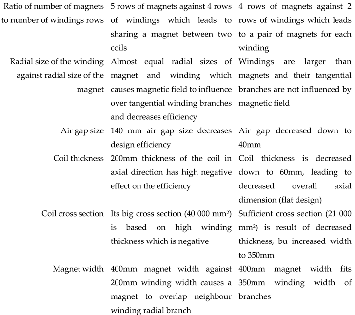
Last stage of design parameters exploration, using developed virtual prototype and numerical techniques to determine values from the electromagnetics dynamic modelling. Obtained results from previous stages are combined with conclusions, derived from results study, and a new design is developed with the following main parameters: number of poles: 48; number of rotor discs: 3; magnet length [mm]: 1800; magnet width [mm]: 400; magnet thickness [mm]: 50; coil width [mm]: 350; coil thickness [mm]: 60; air gap[mm]: 40. Other important specifics are: 4 rows of magnets are used, i.e. the middle wall has two rows of magnets – one on each side; the coils are larger than magnets as to avoid magnet overlapping with tangential sides of the coil.
Performed simulations fully correspond to previous (rotational speed of 13 rpm and simulation model set up), and they are run for three load cases of mechanical input power: 10MW, 14MW, and 18MW. The results are summarized and shown in Figure 9, together with preliminary variants results, for better review and comparison.
Several comments could be formed based on obtained results by the simulations of final design variant:
- Preliminary defined design has insufficient efficiency, reaching ≈75% at 10 MW mechanical power input;
- Best design variant III reaches ≈96% efficiency at 10 MW mechanical power input.
- Final design variant also shows consistent efficiency even at increased upto 18MW mechanical power input, reaching ≈92% efficiency;
- Further feasibility study needs to examine the manufacturability and other technical specifics of developed conceptual design variant.
3.5. Feasibility Study
3.5.1. Axial Generator Efficiency
Axial flux permanent magnet (AFPM) generators have many unique features. For being permanent magnet, they usually are more efficient, as field excitation losses are eliminated, reducing rotor losses significantly. Generator efficiency is thus greatly improved, and higher power density achieved. Axial-flux construction has less core material, so, high torque-to-weight ratio. Also, AFPM machines have thin magnets, so are smaller than radial flux counterparts. The noise and vibration they produce are less than those of conventional machines.
Their air gaps are planar and easily adjustable. Also, direction of main air gap can be varied, so derivation of various discrete topologies is possible. These benefits give AFPM generators advantages over conventional machines, in various applications.
The efficiency is the major point of generator choice and design. It reflects not only over thermal behavior (power losses are heat dissipated), but also at the overall price performance of the product. Generally, all available studies shows ≈97% efficiency for this type of generators.
Efficiency depends also on applied load (mechanical power input) as with the increase of current density in the windings, the power output increases, but slower than the increase of the losses. This shows the need for examination of designs at various loads – mechanical power input.
Initially, the preliminary defined design is examined in detail, and after several iterations, an improved design is proposed. Major reasons for obtained improved efficiency are listed below in Table 1.
3.5.2. Manufacturability and Mechanical Solution
The generator has outer diameter of nearly 14 meters and its manufacturing needs to use technologies, typical for large structures. Several points could be raised at this phase of the product development process:
- Magnet production and mounting: NdFeB magnets are manufactured by arranging the crystal orientation of NdFeB magnet powder in a particular direction using an external magnetic field, applying mechanical pressure to the mold and sintering it through powder metallurgy. In line with this process, the electromagnet used to apply the magnetic field is incorporated into the press. Due to the limitations of the electromagnet’s performance, the maximum size of a magnet manufactured in one press is approx. 100 mm2. Existing studies for similar structures [27] use production technology for the magnet by assembling magnet blocks measuring 100 mm x 100 mm x 50 mm. These blocks are bonded to an iron plate, which is then bolted to the rotor disk, as NdFeB magnets are fragile and threaded holes cannot be made in them (refer to Figure 10). Magnetic blocks are bedded and bonded to a back plate before magnetizing. Then, the unit is completed by one magnetizing process using the superconductive magnetizing equipment. Another problem is to insert magnets into the structure as it is rather difficult to control the unit due to the strong magnetic attractive force toward the rotor in the method where the unit is lowered to the rotor.
- Windings assembly: Improved generator design has two rows of coils. Each row consists of 2x 36 coils, placed over a 10mm thick aluminum plate – on each side of the plate has 36 coils. Another two side aluminum plates are mounted as to improve cooling of the module. This is shown in general on Figure 11. Another design specific of the winding is that it is flat – 30mm thickness allows using a single coil row in its thickness which facilitates winding manufacturing.
4. Discussion
Existing experience, presented in current research studies, and numerical simulations (electromagnetic analyses using Virtual Prototype) results and data were here collected and studied. Initially proposed design was improved reaching ≈96% efficiency. Improved design also has decreased number of magnets and coils that decreases production cost too. Additionally, technical risk assessment focuses further design development on next major directions:
- cooling system (high fluid flow solution will be probably needed);
- production of magnets – special attention needs to be paid on the magnets assembling and mounting;
- coils production and mounting on aluminum plates (disks).
Further research is needed to better understand the performance of the generator. Building and testing a physical scaled down prototype is an important step in further design development. This study is based on virtual prototyping of electromagnetic of large scale AFPM generator, and shows a good feasibility of the examined conceptual design.
5. Conclusions
The main purpose of this paper is to present the application of virtual prototyping in assessment of large structure, where physical prototyping is expensive and time consuming approach. It also presents the strengths of virtual prototyping in the evaluation of design parameters and their influence over searched performance. Finally, but not at least, it is a good sample of applied scientific approach to a real engineering problematics area, that is also very actual – green energy harvesting.
Author Contributions
Conceptualization, G.T. and K.K.; methodology, K.K.; software, B.Z.; validation, G.T. and K.K.; formal analysis, G.T.; investigation, K.K.; resources, B.Z.; data curation, B.Z.; writing—original draft preparation, K.K. and B.Z.; writing—review and editing, G.T.; visualization, B.Z.; supervision, G.T.; project administration, G.T.; funding acquisition, K.K. All authors have read and agreed to the published version of the manuscript.
Funding
This study is financed by the European Union-Next Generation EU, through the National Recovery and Resilience Plan of the Republic of Bulgaria, project № BG-RRP-2.004-0005 and by the project КП-06-Н47/8 „Research of innovative AXial induction high-efficiency MOTOrs with squirrel-cage rotor of a new generation for electric vehicles - AxMoto“.
Data Availability Statement
The data presented in this study are available on request from the corresponding author. The data are not publicly available due to relation to public funding specifics.
Conflicts of Interest
The authors declare no conflicts of interest.
References
- Agency, I.E. Electricity Mid-Year Update, July 2024. IEA Publications. 2024.
- Banja, M.; Monforti, F.; Scarlat, N. Review of technical assessment of national renewable energy action plans. JRC scientific and policy reports 2018. ISPRA, Italy: European Commission, Directorate-General Joint Research Centre, Institute for Energy and Transport.
- Quaranta, E. Stream water wheels as renewable energy supply in flowing water: Theoretical considerations, performance assessment and design recommendations. Energy for Sustainable Development 2018, 45, 96–109. [Google Scholar] [CrossRef]
- de Faria, F.; Jaramillo, P. The future of power generation in Brazil: An analysis of alternatives to amazonian hydropower development. Energy for Sustainable Development 2017, 41, 24–35. [Google Scholar] [CrossRef]
- Niebuhr, C.M.; van Dijk, M.; Neary, V. S.; Bhagwan, J.N. A review of hydrokinetic turbines and enhancement techniques for canal installations: Technology, applicability and potential. Renewable and Sustainable Energy Reviews 2019, 113, 109240. [Google Scholar] [CrossRef]
- Chica, E.; Rubio-Clemente, A. Design of Zero Head Turbines for Power Generation. Renewable Hydropower Technologies 2017, 25–50. [Google Scholar]
- Muljadi, E.; Wright, A.; Gevorgian, V.; Donegan, J. , Marnagh, C.; McEntee, J. Power Generation for River and Tidal Generators. National Renewable Energy Laboratory, Golden, CO, USA, 2016.
- Balaka, R.; Rachman, A.; Delly, J. Blade Number Effect for A Horizontal Axis River Current Turbine at A Low Velocity Condition Utilizing A Parametric Study with Mathematical Model of Blade Element Momentum. Journal of Clean Energy Technologies 2014, 2. [Google Scholar] [CrossRef]
- Khan, М. Bhuyan, G.; Iqbal, M.; Quaicoe, J. Hydrokinetic Energy Conversion Systems and Assessment of Horizontal and Vertical Axis Turbines for River and Ridal Applications: A Technology Status Review. Applied Energy 2009, 1823–1835.
- Babu, B.; Divya, S. Comparative study of different types of generators used in wind turbine and reactive power compensation. IOSR Journal of Electrical and Electronics Engineering 2017, 95–99. [Google Scholar]
- Beainy, A.; Maatouk, C.; Moubayed, N.; Kaddah, F. Comparison of different types of generator for wind energy conversion system topologies. In 3rd International Conference on Renewable Energies for Developing Countries (REDEC), Zouk Mosbeh, Lebanon, (2016).
- Parol, M.; Arendarski, B.; Parol, R. Calculating electric power and energy generated in small wind turbine-generator sets in very short-term horizon. in E3S Web of Conferences, 2019.
- Sheryazov, S.; Issenov, S.; Iskakov, R.; Kaidar, A.B. The main types of wind turbines-generators in the power supply system 2022. Power engineering: research, equipment, technology.
- Cao, W.; Xie, Y.; Tan, Z. Wind Turbine Generator Technologies. 2012.
- Douglas, S. Large Hydrokinetic Turbine Generation Is Here! Canadian Perspectives 2017, Evolving Technologies, vol. 1.
- Koondhar, M.A.; Afridi, S.K.; Saand, A.S.; Khatri, A.R.; Albasha, L.; Alaas, Z.; Graba, B.B.; Touti, E.; Aoudia, M.; Ahmed, M. Eco-Friendly Energy From Flowing Water: A Review of Floating Waterwheel Power Generation. IEEE Access 2024, 12, 90181–90203. [Google Scholar] [CrossRef]
- Izzat, F.; Sarip, S.; Kaidi, H.M.; Shamsudin, N.M.; Hashim, N.; Omar, N.A.; Mat Desa, S. Design Process and Study of Pico Hydroelectric Floating Waterwheel Turbine. International Journal of Emerging Trends in Engineering Research 2020, 8. [Google Scholar]
- Gandhi, J.R.; Jha, H.; Jha, S.N.; Patel, D.S. Renewable Energy Based Floating Power Generator (Rivers and Canals). International Journal of Engineering Research and Applications 2016, 6, 49–52. [Google Scholar]
- Kougias, I.; Aggidis, G.; Avellan, F.; Deniz, S.; Lundin, U.; Moro, A.; Muntean, S.; Novara, D.; Perez-Díaz, J.I.; Quaranta, E.; Schild, P.; Theodossiou, N. Analysis of emerging technologies in the hydropower sector. Renewable and Sustainable Energy Reviews 2019, 113, 109257. [Google Scholar] [CrossRef]
- Quaranta, Е.; Revelli, M. Gravity water wheels as a micro hydropower energy source: A review based on historic data, design methods, efficiencies and modern optimizations. Renewable and Sustainable Energy Reviews 2018, 97, 414–427. [Google Scholar] [CrossRef]
- Quaranta, Е.; Revelli, M. CFD simulations to optimize the blade design of water wheels. Drinking Water. Energy and Science 2017, 10, 27–32. [Google Scholar] [CrossRef]
- Hameed, J.A.; Saeed, A.T.; Rajab, M.H. Design and Study of Hydroelectric Power Plant by Using Overshot and Undershot Waterwheels. International Journal of Energy Optimization and Engineering 2019, 8. [Google Scholar] [CrossRef]
- Carruthers, D.; Carruthers, P.; Wade, R. A new, more efficient waterwheel design for very-low-head hydropower schemes. Proceedings of the Institution of Civil Engineers: Civil Engineering.
- Todorov, G.; Kamberov, K.; Semkov, M. Numerical modelling of two phase stream through undershot water wheel. AIP Conference Proceedings 2021. [Google Scholar]
- Mostaman, N.A.; Sulaiman, E.; Jenal, M. Overview of Axial Flux Permanent Magnet Generator for Small-Scale Industry. IOP Conference Series: Earth and Environmental Science 2023, 1261, 012004. [Google Scholar] [CrossRef]
- Kim, S.-A.; Li, J.; Choi, D.-W.; Cho, Y.-H. Design and analysis of Axial Flux Permanent Magnet Generator for Direct-Driven Wind Turbines. International Journal of Power Systems 2017, 8. [Google Scholar]
- Kobayashi, H.; Doi, Y.; Miyata, K.; Minowa, T. Design of the axial-flux permanent magnet coreless generator for the multi-megawatts wind turbine. Proceedings of Japan Wind Energy Symposium 2008, 30, 191–194. [Google Scholar]
- Shokri, M.; Behjat, V.; Rostami, N. Characterization of Axial Flux Permanent Magnet Generator Under Various Geometric Parameters for Improved Performance. Gazi University Journal of Science 2015, 28, 285–294. [Google Scholar]
- Lee, J.-Y.; Lee, J.-H.; Nguyen, T.K. Axial-Flux Permanent-Magnet Generator Design for Hybrid Electric Propulsion Drone Applications. Energies 2021, 14, 8509. [Google Scholar] [CrossRef]
- Shariati, O.; Behnamfar, A.; Potter, B. An Integrated Elitist Approach to the Design of Axial Flux Permanent Magnet Synchronous Wind Generators (AFPMWG). Energies 2022, 15, 3262. [Google Scholar] [CrossRef]
- Gołębiowski, L.; Gołębiowski, M.; Mazu, D. Analysis of axial flux permanent magnet generator. COMPEL - The international journal for computation and mathematics in electrical and electronic engineering 2019, 38, 1177–1189. [Google Scholar] [CrossRef]
- Todorov, G.; Kamberov, K.; Ivanov, T. Parametric optimisation of resistance temperature detector design using validated virtual prototyping approach. Case Studies in Thermal Engineering 2021, 28. [Google Scholar] [CrossRef]
- Malakov, I.; Zaharinov, V. Optimization of size ranges of technical products. Applied Mechanics and Materials 2016, 859, 194–203. [Google Scholar] [CrossRef]
- Usman, H.; Ikram, J.; Alimgeer, K.S.; Yousuf, M.; Bukhari, S.S.; Ro, J.-S. Analysis and Optimization of Axial Flux Permanent Magnet Machine for Cogging Torque Reduction. Mathematics 2021, 9, 1738. [Google Scholar] [CrossRef]
- Grozdanov, D.; Tarnev, K.; Hinov, N. Electromagnetic Modeling and Thermal Analysis of a Non-Axisymmetric System for Induction Brazing. Energies 2020, 13, 3656. [Google Scholar] [CrossRef]
Figure 1.
Large scale electricity generator installations: (a) 2 MW turbine with a permanent magnet ring generator [15]; (b) Gorlov turbine as a horizontal-axis river turbine [7].
Figure 1.
Large scale electricity generator installations: (a) 2 MW turbine with a permanent magnet ring generator [15]; (b) Gorlov turbine as a horizontal-axis river turbine [7].
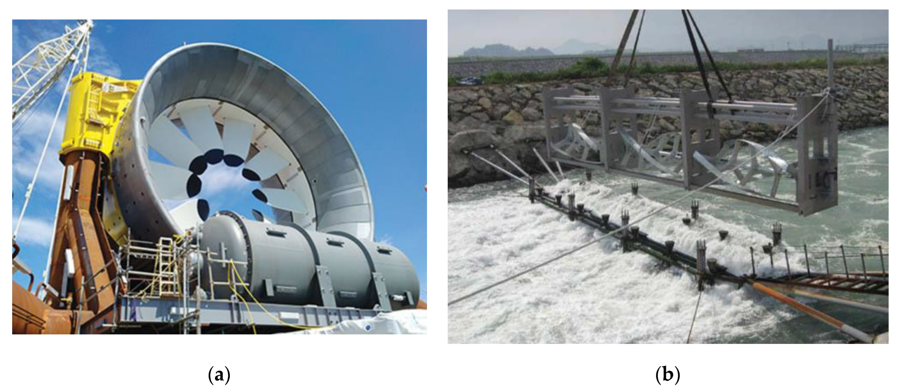
Figure 2.
Floating hydropower plant with water wheel: (a) General concept; (b) Assembly of gearbox and generator.
Figure 2.
Floating hydropower plant with water wheel: (a) General concept; (b) Assembly of gearbox and generator.
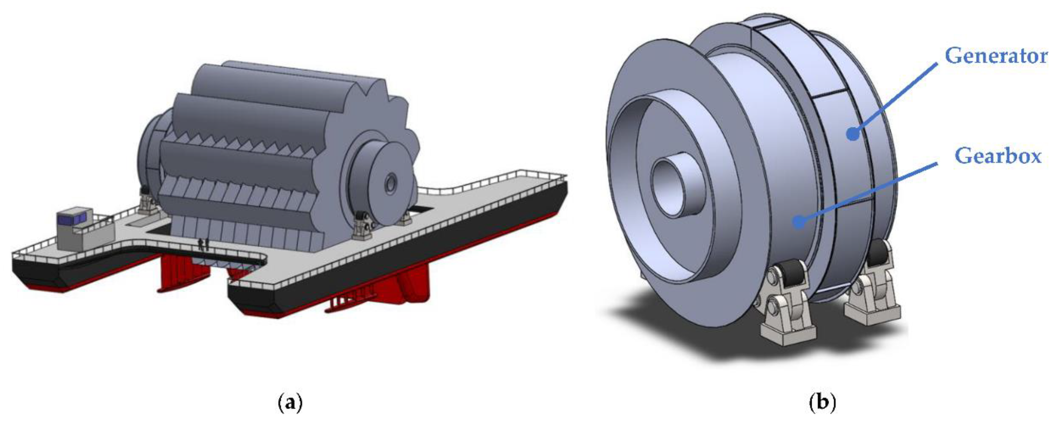
Figure 3.
Preliminary AFPM concept: (a) Characteristic dimensions and schematics, (b) Virtual prototype of geometry.
Figure 3.
Preliminary AFPM concept: (a) Characteristic dimensions and schematics, (b) Virtual prototype of geometry.
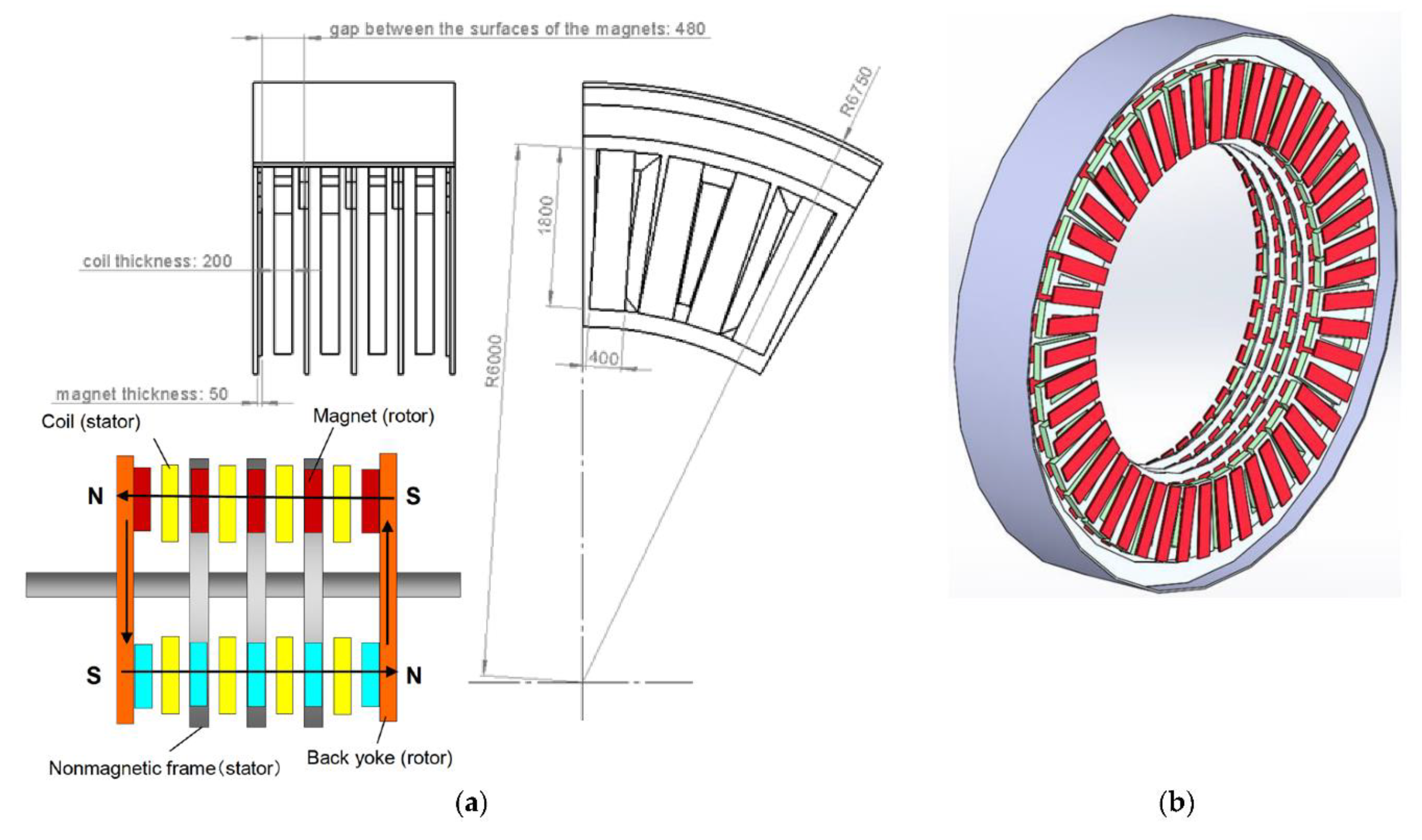
Figure 4.
Scheme of planned design study stages and variants.
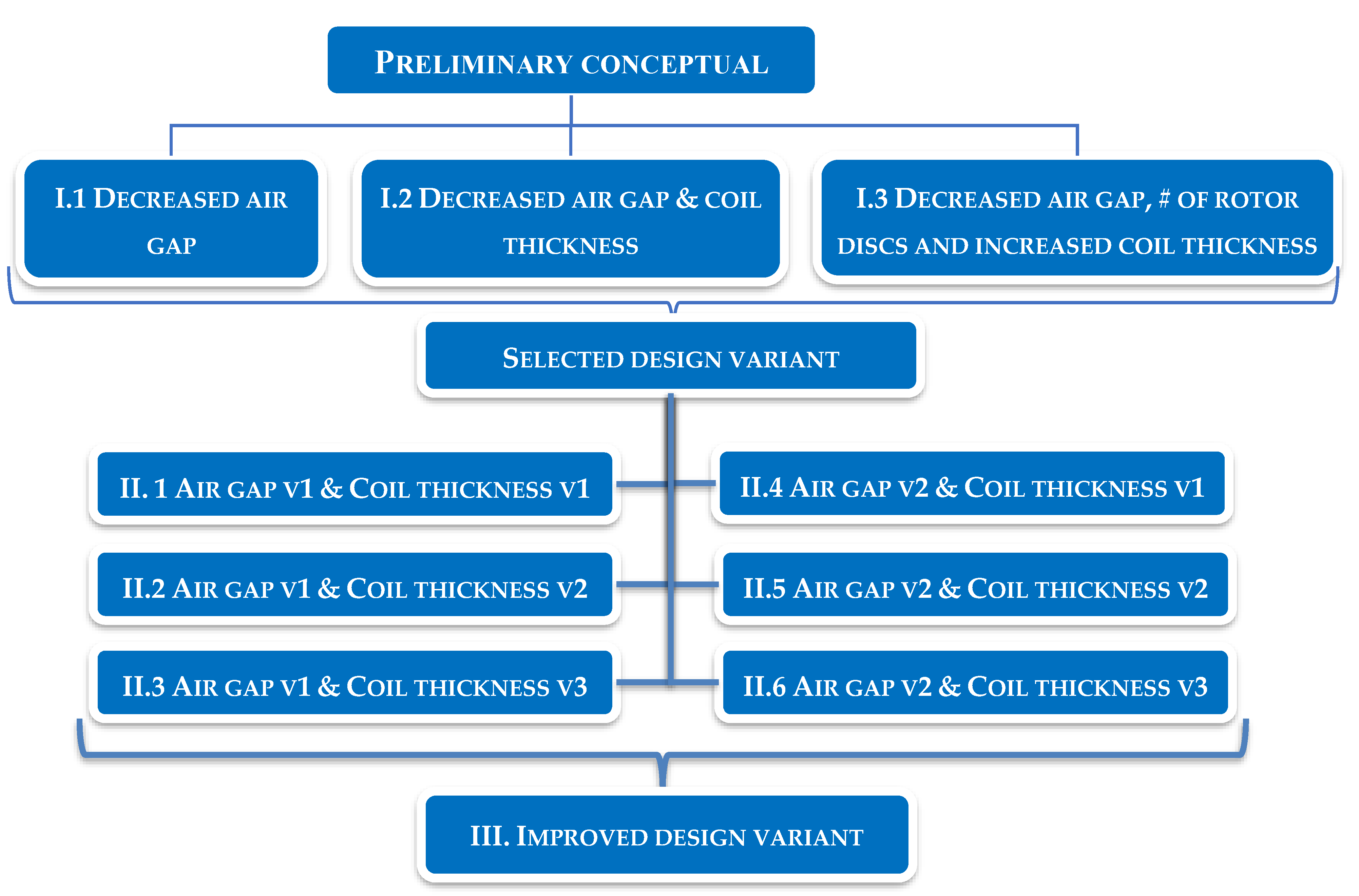
Figure 5.
Results for 10MW load case: (a) Torque variations over time, *106 Nm; (b) Total magnetic field intensity distribution field, A/m.
Figure 5.
Results for 10MW load case: (a) Torque variations over time, *106 Nm; (b) Total magnetic field intensity distribution field, A/m.
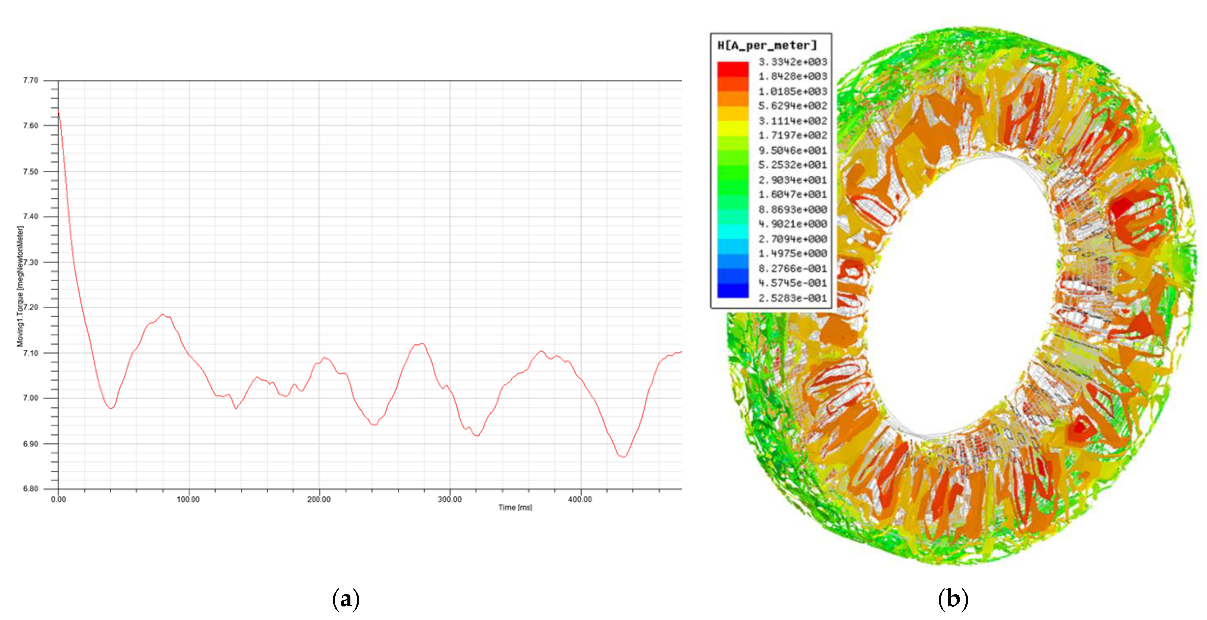
Figure 6.
Power loss and efficiency variation over mechanical torque change.
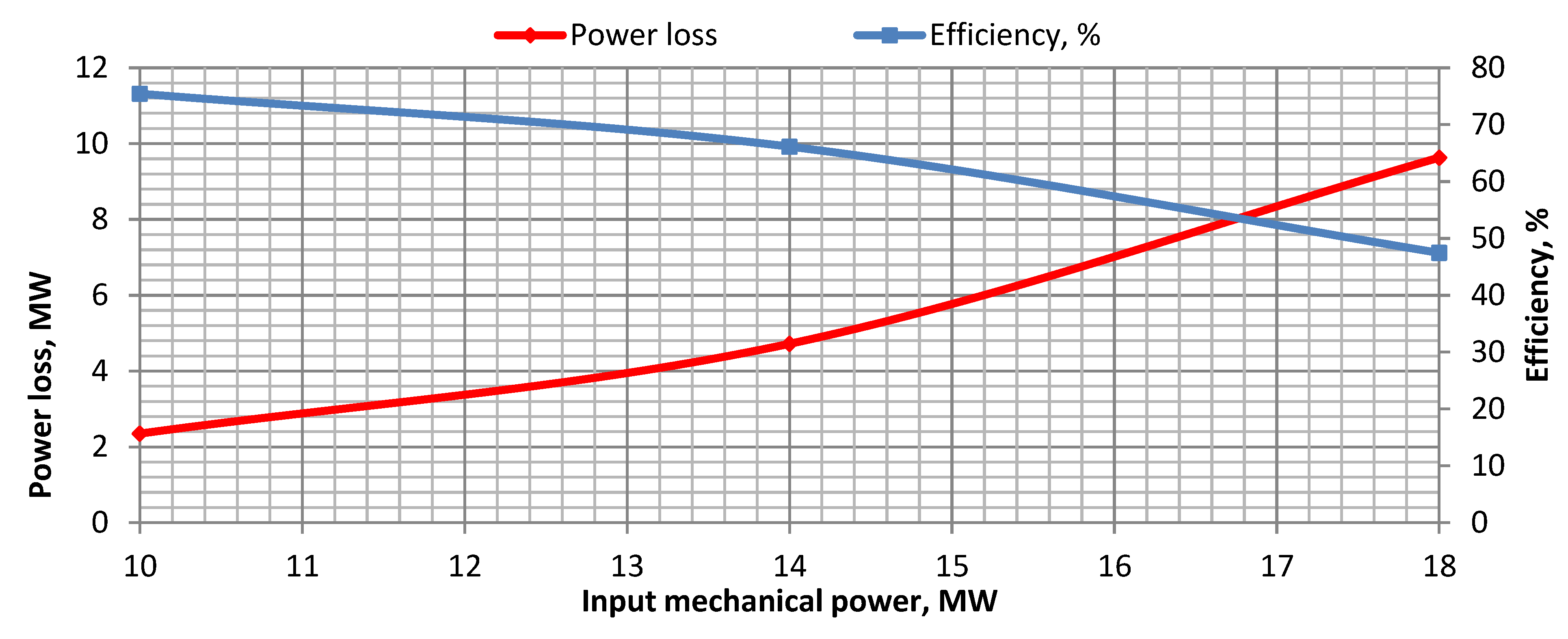
Figure 7.
Power loss and efficiency for examined variants of stage I.
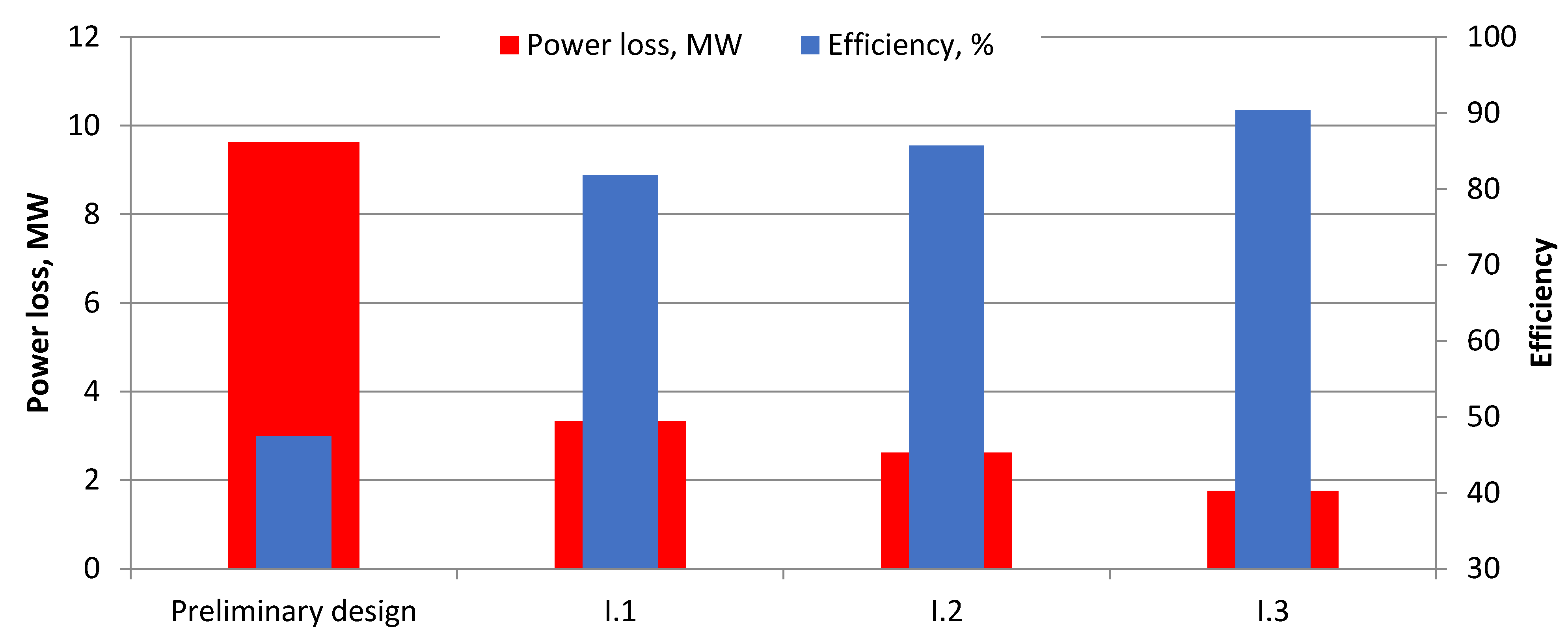
Figure 8.
Power loss and efficiency for examined variants of stage II.
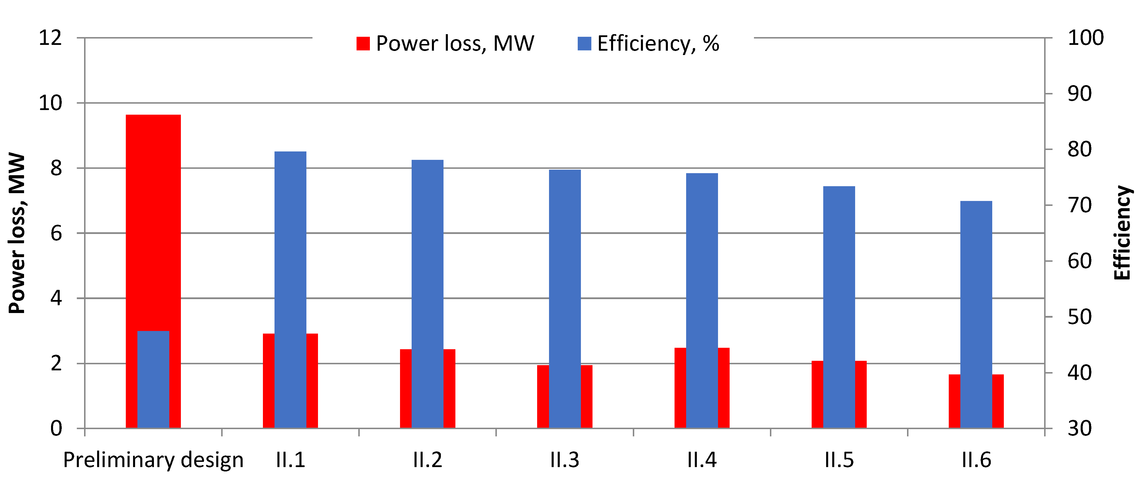
Figure 9.
Comparison between preliminary and improved design by power loss and efficiency variation over mechanical torque change.
Figure 9.
Comparison between preliminary and improved design by power loss and efficiency variation over mechanical torque change.
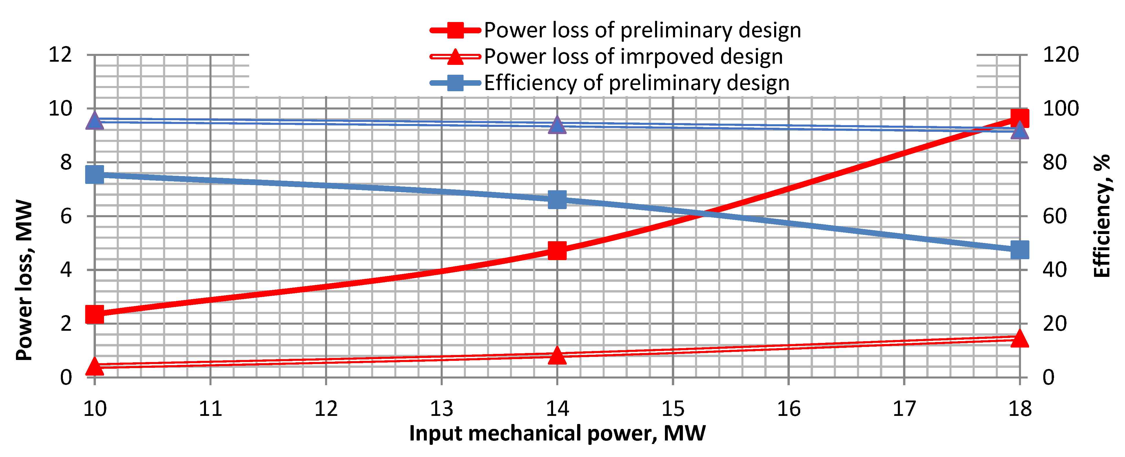
Figure 10.
Magnet design and mounting [27].
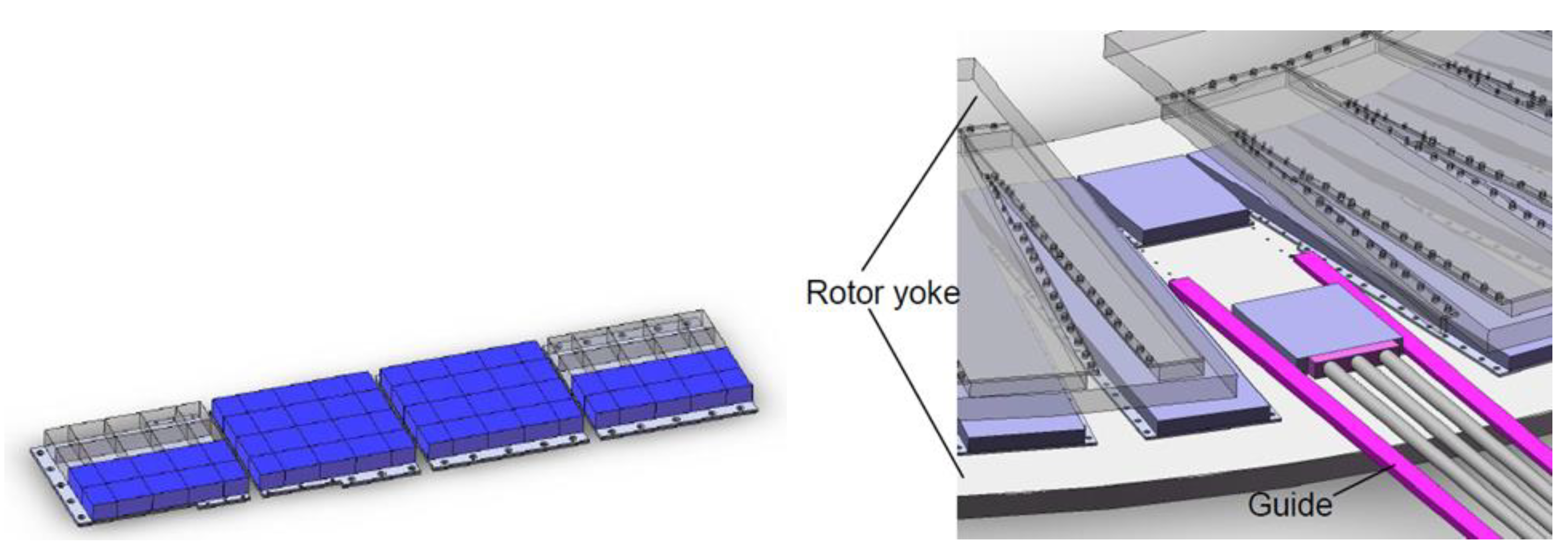
Figure 11.
Coils and placed aluminum alloy plates.
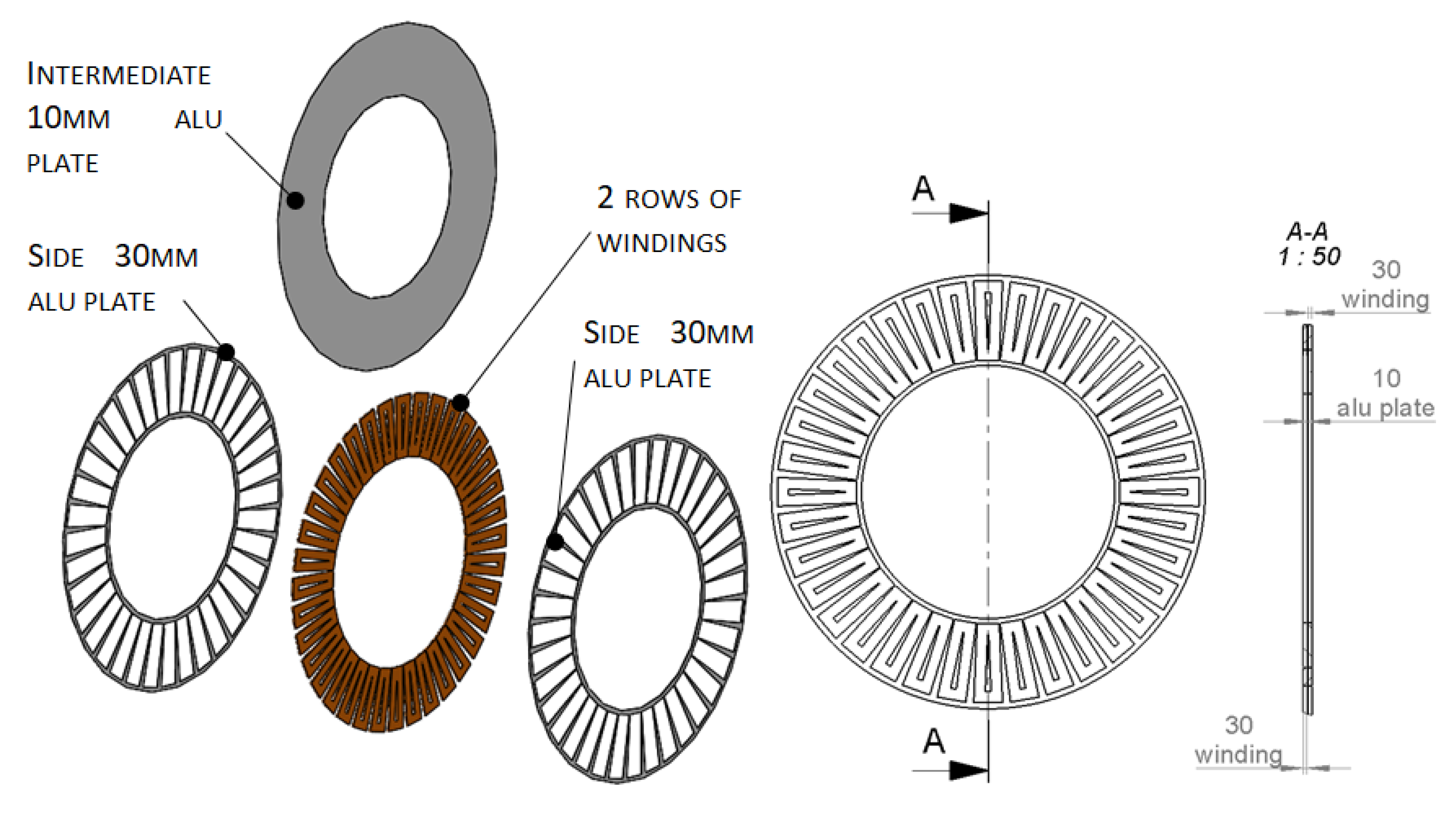

Table 1.
Improvements and their influence to reach better efficiency.
| Parameter | Preliminary defined design | Improved final design |
 | ||
Disclaimer/Publisher’s Note: The statements, opinions and data contained in all publications are solely those of the individual author(s) and contributor(s) and not of MDPI and/or the editor(s). MDPI and/or the editor(s) disclaim responsibility for any injury to people or property resulting from any ideas, methods, instructions or products referred to in the content. |
© 2024 by the authors. Licensee MDPI, Basel, Switzerland. This article is an open access article distributed under the terms and conditions of the Creative Commons Attribution (CC BY) license (http://creativecommons.org/licenses/by/4.0/).
Copyright: This open access article is published under a Creative Commons CC BY 4.0 license, which permit the free download, distribution, and reuse, provided that the author and preprint are cited in any reuse.


