
Submitted:
21 October 2024
Posted:
22 October 2024
You are already at the latest version
Abstract
Digital terrestrial television is now implemented in many world wide countries and is
now mature. Digital Video Broadcasting-Terrestrial, second generation (DVB-T2) is the European
standard adopted or deployed by European and African countries which uses Orthogonal Frequency
Division Multiplexing (OFDM) modulation to achieve a good throughput performance. However,
its main particularity is the number of subcarriers operated for OFDM modulation which is high
(up to 32768). Also, mobile reception is planned in DVB-T2 in addition to rooftop antenna and
portable receptions planned in DVB-T. But, the main challenge of DVB-T2 for mobile reception is the
presence of Carrier Frequency Offset (CFO) which degrades the system performance by inducing
an InterCarrier Interference (ICI) on DVB-T2 signal. This paper evaluates the system performance
in the presence of the CFO when Gaussian noise and TU6 channel are applied. Universal Filtered
Multicarrier (UFMC) and Non Uniform Constellations (NUCs) have previously demonstrated good
performances in comparison with OFDM and Quadrature Amplitude Modulation (QAM) in DVB-T2.
The impact of CFO on the UFMC and NUCs based DVB-T2 system is additionally investigated in
this work. The results demonstrate that the penalties induced by CFO insertion in UFMC and NUCs
based DVB-T2 are highly reduced in comparison to those for the native DVB-T2. At a BER of 10−3,
the CFO penalties induced by the native DVB-T2 are respectively 0.96 dB and 4 dB when only AWGN
is used and when TU6 is additionally considered. The penalties are equals to 0.84 dB and 0.2 dB for
UFMC/NUCs based DVB-T2.
Keywords:
channel coding
; multicarrier modulation
; DVB-T2
; UFMC NUC
; CFO
1. Introduction
Digital Video Broadcasting-Terrestrial, second generation (DVB-T2) standard constitutes the evolved version of Digital Video Broadcasting-Terrestrial, first generation (DVB-T) that meets the ever growing demand of the high definition television (HDTV), ultra high definition television (UHDTV), and mobile TV services. This standard has been adopted or deployed by most European and African countries. In particular as African countries took their time to migrate from analog to digital, going directly to the DVB-T2 system presents many performances that were not considered in DVB-T. DVB-T2 system highlights include the use of mobile reception services, the use of advanced channel coding techniques, and source coding methods, and the use of “Multiple Physical Layer Pipes” concept for data transmission [1]. All these DVB-T2 system advantages motivated researchers to have a significant interest to the DVB-T2 system-related topics since its standardization in 2009 [2].
The multicarrier modulation technique defined in DVB-T2 is OFDM (Orthogonal Frequency Division Multiplexing) that presents many benefits such as the reduction of the impact of Intersymbol Interference (ISI) and the increase of the spectral efficiency in comparison with a Single Carrier Modulation (SCM). However, it suffers from some drawbacks like synchronization problems and the reduction of spectral efficiency due to the insertion of Cyclic Prefix (CP). These synchronization problems are accentuated by the presence of Carrier Frequency Offset (CFO) on DVB-T2 signal at the receiver side. CFO is defined as the frequency offset induced by the mobility of the receiver, or by the frequency offset of the local oscillator. To estimate the CFO in DVB-T2 system, P1 symbols are inserted at the beginning of each physical layer frames. A P1 symbol consists of three sections: the central section is generated by an inverse Fourier transform of a sequence of OFDM symbols, and the other two sections, respectively added before and after the central one, are frequency-shifted repetitions of some samples of the central section and are viewed as guard intervals [3,4]. The central section is a 1K OFDM symbol that contains some basic Transmission Parameters Signalling (TPS) such as the FFT size and the Single Input Single Output (SISO)/Multiple Input Multiple Output (MIMO) mode [3]. Therefore, it can not be considered as a training sequence since the signaling symbols used are not known[4]. More accurate estimation methods have been proposed in the scientific literature during these last decades to increase the performance of the classical CFO estimator used in DVB-T2 [3,4,5,6,7,8]. However, a research gap is noticeable on the estimation of the CFO presence effect on the performance of this system.
Furthermore, many advanced multicarrier modulation techniques have been recently studied with the advent of 5G communication system. These are Universal Filtered Multicarrier (UFMC), Filter Bank Multicarrier (FBMC), Generalized Frequency Division Multiplexing (GFDM) and and Filtered-Orthogonal Frequency Division Multiplexing (F-OFDM)[9,10]. The specificity of these modulations is to add novel signal processing techniques to deal with OFDM drawbacks. UFMC and FBMC performance have been mainly studied in DVB-T2 by comparing them to the classical OFDM performance. It resulted that these modulations present better BER performance without channel coding and these outcomes are highly robust when channel coding techniques are used. In particular, UFMC has been distinguished as the modulation that presents better performance than OFDM and FBMC as well as similar computational complexity when compared to OFDM [9,11]. Indeed, the specificity of DVB-T2 is to use high subcarrier numbers as parameters which increases the OFDM symbol duration and then allows achieving a better network coverage. However, as the number of subcarriers increases, the inter-carrier spacing decreases. Thus, a deployed DVB-T2 network using a large number of subcarriers is more sensitive to frequency offset at the reception side than others using a small number of subcarriers. Therefore, the study of CFO impact in DVB-T2 system is relevant to support broadcasters which planning to broadcast audio-visual signals for mobile reception case. Furthermore, to the best of authors knowledge, the impact of CFO has not yet been studied in UFMC in the frame of a DVB-T2 configuration. This paper is filling these gaps by evaluating the impact of CFO in both the native DVB-T2 system as a comparison basis and UFMC based DVB-T2 system. The main evaluation parameters are Bit Error Rate (BER), Modulation Error Ratio (MER) and Error Vector Magnitude (EVM) as these parameters are frequently used in digital signal measurement. The organization of this paper is shown in Figure 1. The outline of this paper is presented as follows: the related works about this topic are firstly presented (§II). It is followed by the theoretical background about multicarrier modulations and radiofrequency impairments (§III). The material and methods are presented (§IV) is followed by the results (§V) and a discussion (§VI). The paper ends with the conclusion (§VII).
2. Related Works
OFDM and UFMC are multicarrier modulations which constituted a subject of research interest during the last decade. OFDM is mainly used in many communication systems such as DVB-T [12], DVB-T2 [2], Advanced Television Systems Committee, third generation (ATSC 3.0) [13], Visible Light Communication (VLC)[14], 4G [15] and 5G [16]. Carrier Frequency Offset (CFO) is a radiofrequency impairment induced respectively by oscillator frequency mismatch between the transmitter and the receiver also known as Doppler shift. This section presents the literature review.
2.1. Multicarrier Modulations in DVB-T2
Previously, related works about CFO use cases and multicarrier modulation in DVB-T2 have been presented. This subsection presents papers that compare OFDM and UFMC performance in DVB-T2.
In 2020, filter based waveforms UFMC and FBMC have been studied and their performances were compared to OFDM using DVB-T2 system parameters and its channel coding technique [9]. The numerical results have proven that UFMC outperforms FBMC which performances have previously been confirmed in DVB-T[17] and DVB-T2 systems [18] using BER after demapping and decoding. Furthermore, the spectral efficiency of these waveforms has been studied and compared to the 100% OFDM spectral efficiency.
In 2021, UFMC has been jointly studied with Non Uniform Constellation (NUC) in the frame of DVB-T2 system. Indeed, Quadrature Amplitude Modulation (QAM) and Orthogonal Frequency Division Multiplexing (OFDM) are the modulations techniques used in DVB-T2 [19]. Advanced constellation shape technique called NUC has been integrated in ATSC 3.0 as it presents better performance than the square shape constellation. This constellation has then been inserted in [19] in both the native DVB-T2 and the UFMC based DVB-T2 system to measure the impact. The main conclusion is the UFMC NUC based DVB-T2 system performance is really better than that of the native DVB-T2 system.
Moreover, during the same year, the same authors worked on the computational complexity of filter-based waveforms (FBMC and UFMC) proposed in DVB-T2 context improvement [20]. The purpose of this study was to highlight the optimal low complexity algorithm. Furthermore, the compromise between FBMC and UFMC waveforms applied to DVB-T2 in terms of Signal to Noise Ratio (SNR) performance gains, spectral efficiency, and complexity is established. The results have shown that UFMC is the waveform whose complexity can be reduced to OFDM complexity and presents higher SNR performance gain with a reasonable spectral efficiency. It is demonstrated that for the same couple of parameters (16K mode and CP 1/4) that present the larger CP overhead in DVB-T2, UFMC is 128.51% spectrally more powerful than OFDM. These performance are possible with UFMC as there is no need to add CP to achieve a good BER performance than OFDM.
2.2. CFO Case Studies in Multicarrier Modulations
CFO results in InterCarrier Interference (ICI) by breaking the orthogonality between subcarriers. This part presents papers that investigated CFO case studies in multicarrier modulations, and DVB-T2 in particular.
In 2006, a suboptimal scheme is proposed for OFDM systems to estimate the CFO using null subcarriers (ie., subcarriers with zero transmitted) [21]. This scheme is based on the exploitation of one OFDM training sequence in which it is imposed to use the odd subcarriers indexes like null subcarriers in first and to carry pilot tones by the even subcarriers indexes. The work is performed assuming that the guard interval is longer than the Channel Impulse Response (CIR) length and the time synchronization is perfect. The specificity of this scheme is a reduced implementation complexity compared to the previous work as the main component requisite is a simple correlator. Furthermore, null subcarrier allocation for the optimal Maximum Likelihood CFO estimation has been also investigated using an extended m-sequence. It was demonstrated that this method presents an improved performance compared to the previous one based on the principle of null subcarriers with distinct spacing.
In 2012, an optimum Maximum Likelihood (ML) synchronization method for P1 symbols was proposed [7]. Indeed, P1 symbol is obtained in a similar way as for an OFDM symbol. However, its features are different from a classical OFDM symbol and therefore are not really exploited by synchronization algorithms developed for multicarrier systems. The authors of this paper exploit the tripartite structure of the P1 symbol and the presence of null subcarriers in the vector transformed by inverse Fourier transform. For the purpose of complexity reduction, ML synchronization for OFDM systems with no training sequence has been used in parallel with the implementation of null subcarriers in OFDM symbols. Furthermore the Cramèr-Rao Lower Bound for the new scheme CFO estimator has been investigated. This solution presents an optimal performance while having a much lower complexity than that of the classical ML solution.
In the same year (2012), an ICI cancellation method has been studied for DVB-T2 system including MISO technique [3]. Indeed, the P1 symbol inserted at the beginning of each T2 frame is used to estimate CFO. This symbol presents a frequency-shifted guard interval at both ends which improves the correlation between the central part of the P1 symbol and the two intervals. Then, the estimation is performed by correlating the received P1 symbol and by recovering the argument of the correlator output’s peak. When the MISO technique is exploited in DVB-T2, the signal and a slightly modified version of this signal are transmitted at the same time by two spatially separated transmitters having their own oscillators. This technique induces the signal performance improvement. However, two distinct CFOs, called dual CFOs, may appear in the received signal, one for each transmitter. [3] presents a method to mitigate InterCarrier Interference (ICI) occured due to the dual CFO after performing dual CFOs compensation. It also proposes an iterative detection and ICI cancellation technique with the presence of large CFO. Using this technique, the ICI is eliminated in a successive and iterative manner using the previously detected data samples and a priori LLR values fed from the Low Density Parity Check (LDPC) decoder. The BER versus SNR simulation results showed that the proposed DVB-T2 receiver outperforms the case in which dual CFOs are perfectly known and comes closer to the performance of the ideal dual CFOs-free case.
Moreover, CFO estimation techniques have been presented and their performances were evaluated using Mean Square Error (MSE) [22]. The main estimation techniques presented are time domain estimation (use of cyclic prefix or training sequence) and frequency domain estimation (pilot tones techniques). The simulation has been performed using the CP based technique, Moose (Preamble based techniques) and Classen (Pilot-based techniques). The results have shown that Classen Estimation technique is much more efficient than the other ones.
In 2015, the efficiency of OFDM systems with CFO estimation errors has been measured in terms of spectral efficiency [23]. This work was performed regarding both the degradation in signal-to-interference-plus-noise ratio (SINR) due to the residual CFO, and the penalty of the extra power and spectral resources allocated to achieve the desired CFO estimation accuracy. Indeed, there still is a residual CFO after CFO estimation and compensation at the receiver which may degrade OFDM systems performance. [23] presents the modified formula for the spectral efficiency of OFDM systems by making the trade-off between the following two conflicting factors related to the estimation based CP and the training sequence method. Using too little training symbols induces the increase of CFO estimator errors while too much training symbols induces the loss of power and bandwidth system resources.
During the same year (2015), two ML CFO estimated methods called Stochastic ML (SML) and Deterministic ML (DML) were investigated by modeling the DVB-T2 transmitted signal as a stochastic and, respectively, a deterministic unknown waveform and assuming an unknown fading channel scenario [24] in contrast to the method developed in [4]. It is shown that the proposed deterministic ML method is more flexible and presents a lower computational complexity compared to the SML method but at the cost of reduced estimation accuracy. Numerical results demonstrated that both methods outperform the cross-correlation based method.
In 2016, the Symbol Error Rate (SER) versus SNR of UFMC and OFDM has been evaluated in the frame of 5G assuming the presence of CFO or not and using mobile network system transmission parameters [25]. UFMC and OFDM performance has been firstly compared. The results demonstrated that UFMC outperforms OFDM by 0.8 dB at a SER of . Simulations have been pursued and it is demonstrated that CFO estimator errors varies between these values 10%, 20% and 50%. It is observed that for both OFDM and UFMC, the CFO estimation error critically diminishes the SER performance of the system.
In 2017, other authors also studied UFMC and OFDM performance by evaluating the CFO impact on these multicarrier modulations [26]. Two different detection techniques such as Minimum Mean Square Error (MMSE) and Zero Forcing (ZF) are used. Simulation has been performed by explicitly inserting CFO at the receiver side and calculating SER versus SNR. UFMC Single User and Multi User have been investigated. Also, MIMO technique has been applied to UFMC multicarrier system. The results illustrated the good performance of UFMC when compared to OFDM without CFO and with CFO for single user and multi user in different communication environments.
In this section, related work about CFO and multicarrier modulations in DVB-T2 are presented. It is noticed that many papers present CFO estimation and compensation algorithms in OFDM and DVB-T2. Only two papers address respectively the impact of CFO in OFDM and UFMC. Table 1, Table 2, Table 3 and Table 4 summarize papers by presenting their advantages and their limitations. To the best of our knowledge, there is no work that addresses CFO impact on UFMC based DVB-T2. This work is going to fill this gap by evaluating CFO impact on the received signal quality using UFMC and NUCs based DVB-T2.
3. Theoretical Background
3.1. Multicarrier Modulations
Multicarrier modulation (MCM) defines a technique of transporting data over several subchannels of narrow bandwidth instead of conveying the data over the entire bandwidth in Single Carrier Modulation (SCM) schemes. MCM is known as technique that uses multiple carrier signals at different frequencies, sending some of the bits on each subchannel. The main advantages of MCM are summarized as follows: its immunity to multipath fading channels (frequency selective channels in particular), its enhanced Immunity to Intersymbol Interference as the symbol period on each subchannel increases, its spectral efficiency and the resilience to interference. Indeed, each subcarrier represents only a small portion of the total signal. If one subcarrier is lost or corrupted due to interference or noise, the overall signal remains almost intact. This resilience makes multicarrier modulation robust. OFDM is the most popular scheme used in digital video and audio broadcasting as well as Long Term Evolution (LTE) downlink transmissions. However, UFMC modulation is proposed as an alternative for many communication systems including DVB-T2. This section presents these modulations and compares their features.
3.1.1. OFDM
The principle of OFDM is to group numerical data per packages, and to modulate each data by a different subcarrier at the same time. In this section, OFDM block diagram is presented and the numerical expression of the modulation is developed.
-
Transceiver descriptionOFDM transceiver scheme is presented in Figure 2. This modulation consists in three main steps: the symbol mapping, the Inverse Fast Fourier Transform (IFFT) processing (time to frequency domain signal processing) and the Cyclic Prefix (CP) addition in emission. In reception, the steps are: the CP cancellation, the Fast Fourier Transform (FFT) processing and the symbol demapping. In DVB-T2, the symbol mapping method exploited is QAM. This mapping is performed on data containing redundant bits added by LDPC Forward Error Correction (FEC) coder. After the mapping method in emission, the frequency domain signal undergoes IFFT operation which transforms the signal in a time domain signal. The resulting signal is transmitted. The fading channel effects are applied to it. Also the AWGN is added to the signal obtained after fading channel. In reception, the FFT operation is done to convert the time domain signal into a frequency domain signal. As known, CP and guard band include non useful data, participate to spectral efficiency reduction but allow to reduce Intersymbol Interference (ISI) and Adjacent-Channel Interference (ACI) impacts. Figure 3 shows the CP insertion process. denotes the CP duration. The OFDM symbol duration is extended using CP which represents the copy of a part of the OFDM symbol at the starting point of each symbol.
-
Numerical signal expressionThe numerical development is performed assuming complex data symbols named ∈ (, , ,...., ). These data are QAM symbols formed by the grouping of n bits. The sequence of data normally undergoes the IFFT process. Let us suppose that is the number of OFDM subcarriers and the time period separate two sequences of data. is equal to one OFDM symbol duration. k is an positive integer (). During the modulation process, each is modulated at the high frequency . Each individual signal is then expressed in a complex form as the multiplication of by . Therefore, the main signal corresponding to the total data is shown as follows:As the main peculiarity of OFDM is the orthogonality between subcarriers (orthogonal multiplexing), thus the subcarrier spacing is inversely proportional to the symbol period and is equal to . If we denote the carrier frequency, . Then, can be expressed as:
3.1.2. UFMC
The UFMC technique has exceeded the limitation of the OFDM by adding a generalized pulse shaping filters that assures the frequency and time domain spectral localization. Its main characteristics are: 1) the use of sub-bands filtering instead of subchannel filtering in FBMC, 2) the whole band filtering in F-OFDM, 3) the exploitation of complex data symbol as in OFDM.
-
Transceiver descriptionThe UFMC transceiver scheme is illustrated on Figure 4. As shown, QAM data symbols are divided into sub-groups that undergoe separately IFFT processing and are filtered using sub-band filtering technique. The filter prototype used is the Finite Impulse Response (FIR) Dolph–Chebyshev filter of length L. The aims of introducing FIR filter to filter each subband is to reduce the Out Of Band (OOB) spectrum. All results from the sub-groups data processing are summed up and therefore constitute the UFMC symbol. This symbol is transmitted through fading channel and AWGN is added to the signal. At the receiver side, zero padding technique is used to fill the data of length with zeros samples to reach a length of . The purpose of this zero padding technique is to exploit the FFT processing and filter properties to recover data [9]. Therefore, FFT technique is applied to pass data from time domain to frequency domain. After that, a downsampling technique is applied to recover one sample out of 2 on the whole samples. Finally, the same subchannel equalizer (as applied in OFDM) is also applied on the recovered data to retrieve QAM data symbols.
-
Numerical signal expressionLet us suppose that represents complex data symbols resulting from QAM baseband modulation. As previously presented, the full band of N sub carriers is partitioned into B sub-bands. The number of subcarriers in each sub-band is fixed ( complex QAM symbols). In transmitter section, to cancel sub-band interference, IFFT processing is employed to transform frequency domain signal into time domain signal. At each points, sub-bands are computed and zeros are attributed to unreserved subcarriers. The filtering operation is applied by performing linear convolution between data IFFT processing and the filter components. The time domain transmission x vector (at the input of the channel) for a particular multicarrier symbol is the superposition of the sub-bandwise filtered components, with filter length L and FFT length (for simplicity, the time index m is dropped) [27]:For each of the B sub-bands, indexed i, the complex QAM symbols gathered in representing a frequency domain signal are converted to time domain signal by the IFFT-matrix . includes the relevant columns of the inverse Fourier matrix in accordance with the respective sub-band position within the overall available frequency range. is a Toeplitz matrix, composed of the filter impulse response which is used to perform the linear convolution.
3.2. Non Uniform Constellations
In DVB-T2 system, the uniform QAM constellation scheme is exploited. This constellation is a two dimensional rectangular constellation generally defined by the uniform spacing between constellation symbols. The different constellation symbol numbers also called valence are 4, 16, 64 and 256. However, the most robust against noise and channel uniform constellation is 4-QAM (QPSK). The main specificity of the scheme used in DVB-T2 is the Gray mapping technique which goal is to minimize the bit error probability as the hamming distance between two adjacent symbols is equal to one. Furthermore, the advances of scientific research have given rise to new constellation schemes. There are rotated constellations already proposed in DVB-T2 and Non Uniform constellations (NUCs) proposed in ATSC 3.0. While the former has shown better performance in the presence of frequency selective channel, the latter performance was really highlighted mainly when only Gaussian Noise is used and when also when the Gaussian Noise and a frequency selective channel are present during transmission. Using these constellation shapes, it has been demonstrated that ATSC 3.0 standard performances are better than the DVB-T2 ones [28]. Also it represents the standard closer to the Shannon Limit. Two shapes of Non Uniform Constellations (NUCs) are defined. They are one dimensional 1D-NUCs which maintains the rectangular shape of uniform constellations relaxes the uniformity constraint. The two dimensional NUCs (2D-NUCs) has broken the uniformity constraint as it presents a circular shape. They present better performance than the 1D-NUCs. During the 2D-NUC constellation design, the constellation values can take any shape inside one quadrant and the other three quadrants are derived from the first quadrant by symmetry [29]. In this paper, 2D-NUC developed in ATSC 3.0 is retained for CFO performance evaluation in DVB-T2 system as its performance has been previously shown in [19]. Various shape of constellation are designed by combining a constellation size and code rate of the LDPC channel coding. The 2D-NUC that matched to DVB-T2 parameters 16-QAM and CR 1/2 is the 8/15 2D-NUC (page 186, [13]).
3.3. Radiofrequency Impairment: CFO
Various kinds of RadioFrequency (RF) impairments exist in wireless communication systems. There are thermal and flicker noises, Local Oscillator phase noise, sampling jitter, Digital to Analog Converter (DAC) and Analog to Digital Converter (ADC) quantization noise and clipping, quadrature imbalance, carrier frequency offset (CFO) and sampling frequency offset (SFO) [30]. As previously discussed in the introduction, multicarrier systems are sensitive to synchronization errors. They induce the system performance degradation. This deterioration increases with the number of subchannels. As the DVB-T2 system includes high sub-carrier numbers (1024, 2048, 4096, 8192, 16384, 32768), it constitutes a subject of interest to evaluate the impact of Carrier Frequency Offset (CFO) on the system performance. The description of CFO is presented in the following part.
-
CFO descriptionGenerally, in communication systems the carrier frequencies are generated from frequency synthesizers, commonly Phase-Locked Loop (PLLs), using precise crystal oscillators whose performance is specified with a certain precision in parts per million (ppm) [30]. CFO refers to the deviation of the actual receiver carrier frequency (RX carrier frequency) from the nominal carrier frequency (TX carrier frequency) in these systems. This frequency offset is caused by two factors. The first factor is the Doppler shift due to the relative mobility of the transmitter and the receiver (and even the channel) and the second one is the difference between the frequencies of the local oscillators at transmitter and receiver. As DVB-T2 system represents the case study, only the receiver is mobile. The transmitter is fixed in the terrestrial digital broadcasting system. The CFO impact has to be evaluated in two different cases when only Gaussian Noise is used and when fading channel and Gaussian Noise are used together, OFDM system including frequency offset models are respectively presented in Figure 5 and Figure 6.Let us assume that Carrier Frequency Offset does not change between two consecutive symbols. The received y(n) OFDM symbol when only Gaussian noise is considered and when fading channel and Gaussian noise are considered can then be respectively expressed as equations (4) and (5).
- -
- x(n) is the time domain OFDM transmitted symbol.
- -
- y(n) is the received OFDM symbol.
- -
- -
- W(n) is the Gaussian noise signal added to the frequency shifted signal
- -
- h(n) is the channel impulse response of length
When fading channel is considered during the signal transmission, a convolution operation is applied between each OFDM symbol and channel impulse response (eq. (5)).As previously presented, the main impact of CFO on OFDM subcarrier is the presence on Intercarrier Interference (ICI) between the main subcarriers and the adjacent subcarriers. Figure 7 shows a comparison without and with CFO after the Fast Fourier Transform Operation performed at the receiver side [30]. The greater the CFO value is the more intense the ICI between subcarriers. Then, the ICI increase with the number of subcarriers used per OFDM symbol transmission, as the subcarrier spacing value diminishes when the number of subcarriers increase.-
Doppler effect case study In the case of the receiver mobility, a Doppler shift affects the signal frequency and then the OFDM sub-carriers. According to the moving direction and the various speeds of the receiver, the values of the Doppler shift vary inducing a transmitter frequency decrease or increase [31]. Figure 8 presents an illustration of the Doppler effect when the receiver is moving. Let’s denote!
- -
- the Doppler shift which is also the frequency difference between the transmitter frequency and the receiver frequency, previously called .
- -
- v the vehicle speed which varies ()
- -
- the transmitter frequency ()
- -
- c the speed of the light (electromagnetic wave) ()
- -
- the angle between direction of motion and the line of sight to transmitter ()
There are three specific cases of Doppler shift:- -
- (Case 1) The vehicle is moving towards the transmitter and so , ie , and finally .
- -
- (Case 2) The vehicle is moving away from the transmitter and so , ie ( is negative), and finally .
- -
- (Case 3) The vehicle is driving around the transmitter in circles: , , the transmit frequency remains unchanged.
To conclude, Doppler shift is directly proportional to the carrier frequency of the transmitter. Considering the same OFDM mode (number of subcarriers), the lower the frequency , the smaller the Doppler effect. Hence, the OFDM subcarrier spacing is weakly affected. Conversely, the higher the frequency is, the higher the Doppler effects. Hence the OFDM subcarrier spacing is highly affected.
4. Material and Methods
In this section, the lite version of DVB-T2 system is developed and simulation is performed using Matlab software. The main steps of simulation, the systems implemented and the parameters used are presented.
4.1. Simulation Steps
As DVB-T2 system includes many processing blocks and only the main blocks are implemented in our simulator, the native DVB-T2 system implemented is the lite version of DVB-T2. Three main performance evaluation tools such as BER, MER and EVM are used in this work. The main simulation steps exploited to evaluate CFO performance are highlighted in Figure 9. As shown on this figure, the first step is the development and simulation of the lite version of DVB-T2 system called native DVB-T2 and the UFMC based DVB-T2 system and the CFO insertion. The second step consists in adding LDPC coding in both the systems and evaluating CFO impact. The third step consists in substituting QAM mapping block by 2D-NUCs block in both the native DVB-T2 transmitter and the receiver. The fourth step performs the same task like the previous one but NUCs is inserted in UFMC based DVB-T2. The fifth step consists in comparing CFO impact in the NUCs based DVB-T2 system to the CFO impact in UFMC/NUCs based DVB-T2 system and the last step consists in comparing CFO impact in the native DVB-T2 system to the CFO impact in UFMC/NUCs based DVB-T2 system. It is relevant to remember that simulations are performed when only Gaussian noise is considered and when both Gaussian noise and fading channel are used.
4.2. Implemented Systems and Simulation Parameters
Figure 10 exhibits the implemented system using Matlab. As digital transmission, binary data are transmitted, a random binary data generator is used for data generation. This data undergoes the main signal processing techniques such as LDPC channel coding, QAM mapping and OFDM modulation. The signal gathered passes through the Typical Urban 6 channel model and Gaussian noise is added. As already highlighted in Section 3.3, CFO is included to the signal according to the simulation cases (without fading or with fading channel). The reverse operations are then performed at the receiver side.
Moreover, CFO impact is also evaluated when QAM mapping and OFDM are respectively substituted by 2D-NUCs mapping and UFMC. Figure 11 presents the detailed UFMC/NUCs based DVB-T2 system. The process of CFO insertion is performed before the AWGN adding process.
The parameters used for all simulations are presented in Table 5.
4.3. Figures of Merit
Performance parameters used as figure of merit in our simulations are the followings:
- BER is defined as the ratio of the number of erroneous bits to the number of transmitted bits within a period of time. The lower the number of erroneous bits, the better the system performance. In this work, BER is computed after constellation demapping and LDPC decoder.
- SNR is described as the fraction of the received signal strength over the noise strength within the frequency bandwidth range of operation.
- The MER is viewed as an indicator of the modulation quality of the received signal. It measures the QAM symbols accuracy. In real measurement, this tool takes into account the noise, the channel impairments and the radio frequency impairments. This tool is defined as the ratio between the sum of the squares of the magnitudes of the ideal symbol vectors from the constellation and the sum of the squares of the magnitudes of the symbol error vectors. A logarithm operation is applied to the ratio as the MER value is represented as a power ratio in dB and is defined in (eq. 10) [32]. and are the transmitted symbols ideally recovered at the output the QAM modulator. and are the difference between the transmitted symbols and the real received symbols captured at the input of the QAM demodulator (the errors in the received data points). A high MER value means good signal quality. The MER is approximately equal to the SNR when only white Gaussian noise is present on the signal. The EVM is the parameter for which the lower its value, the better the system’s performance. The formula of EVM is presented in (11). N is the number of data points in the measurement sample. Smax is the magnitude of the vector to the outermost state of the constellation. EVM can be expressed in percentage or dB.
5. Results
In this section, simulation results are presented for OFDM and UFMC case studies in DVB-T2 using BER, MER and EVM performance evaluation tools.
5.1. Performance Evaluation of DVB-T2 Using BER
5.1.1. Native DVB-T2 without LDPC Coder
In this part, CFO impact is shown in the native DVB-T2 system when a fading channel is used or not.
Figure 12 shows the BER evolution in function of the SNR in the native DVB-T2 when only the Gaussian noise is used for various CFO values. One can note that when the CFO is not applied (CFO=0.00), the SNR value is equal to at a BER of . At a SNR value of 20 , the BER values of , , , , and are respectively obtained for CFO values of 0, 0.01, 0.02, 0.03, 0.04 and 0.05. These results show that the system performance decrease in the presence of an increasing CFO and the penality obtained increases with the CFO values. At a BER of , the loss gathered varies from to .
Figure 13 presents the BER evolution in function of the SNR in the native DVB-T2 when TU6 channel and Gaussian noise are used for various CFO values. It is remarkable that when the CFO is not applied, the SNR value equals 42 at a BER of . This value ( 42 instead of ) shows the TU6 channel impact compared to simulation results of Figure 12. In other words, TU6 channel has caused a loss of on the system performance. Also, at the SNR value of 40 , the BER values of , , , , and are respectively obtained for CFO values of 0, 0.01, 0.02, 0.03, 0.04 and 0.05. One can note the performance degradation with the CFO values increase when TU6 channel is used. At a BER of , the loss induced by the CFO varies up to 6 , depending of the CFO value.
5.1.2. UFMC Based DVB-T2 without LDPC Coder
In this part, CFO impact is shown in the UFMC based DVB-T2 system (cf Figure 11) when a fading channel is used or not.
Figure 14 exhibits the BER evolution in function of the SNR in the UFMC based DVB-T2 when only the Gaussian noise is used for various CFO values. One can note that when the CFO is not applied, the SNR value is equal to at a BER of . This result allows to conclude that UFMC based DVB-T2 and the native DVB-T2 present the same performance in the presence of Gaussian noise only. Furthermore, at a SNR value of 20 , the BER values of , , , , and are respectively obtained for CFO values 0, 0.01, 0.02, 0.03, 0.04 and 0.05. One can note that the loss increases with the CFO value. However, the loss induced by the CFO values of 0.04 and 0.05 with UFMC based DVB-T2 are respectively lower than those induced by the CFO values of 0.04 and 0.05 with the native DVB-T2 system. At a BER of , the loss induced by the CFO varies from to 6 in the UFMC based DVB-T2 case. In other words, the loss induced by CFO values of 0.04 and 0.05 in UFMC based DVB-T2 system are respectively 3 and 6 at the BER of when the SNR values are compared to the obtained without CFO. In contrast, the losses induced by CFO values of 0.04 and 0.05 in the native DVB-T2 system are respectively and at the BER of . Then, we can conclude that the impact of CFO is more noticeable with OFDM waveform than UFMC waveform. UFMC is less sensible to CFO than OFDM in AWGN case only as highlighted in [25] which presents the SER versus SNR UFMC performance compared OFDM performance.
Figure 15 shows the BER evolution in function of the SNR in the UFMC based DVB-T2 when TU6 channel is used. By comparing UFMC based DVB-T2 system performance to the native DVB-T2 system performance in TU6 case in Figure 13, one can find that UFMC presents better performance than OFDM when TU6 fading channel is used. When CFO is not applied, at the same BER of , the SNR value of UFMC based DVB-T2 is equal 32 instead of 42 in the native DVB-T2 system. Furthermore, this figure demonstrates that UFMC performance slowly degrades with the increase of the CFO value. The system performance without CFO is approximately equal to the system performance when the CFO value varies from 0.01 to 0.04. For a CFO value of 0.05, the system performance decreases and the loss induced is equal to 14dB at a BER of . One can conclude that UFMC is less sensible to CFO than OFDM in the presence of TU6 channel when coding technique is not implemented in the system as the losses induced are lessened than the those for OFDM which is the same trend as for AWGN only.
Table 6 present a summary about OFDM and UFMC performance in presence of CFO when only AWGN is the impairment considered and when TU6 channel is additionally used.
5.1.3. Native DVB-T2 with LDPC Coder
Previously, the CFO performance in DVB-T2 has been evaluated when coding channel is not applied. Now, LDPC coding is applied in the systems and the CFO performance is evaluated.
Figure 16 gives the results from the BER simulation versus SNR. Firstly, one can note that a BER of is obtained at the SNR value of for a CFO value of 0.00. These results allow to conclude that the simulator presents a good behaviour as it is highlighted in the DVB-T2 implementation guidelines [33]. Moreover, the system performance diminishes when CFO is considered and this reduction is more prominent with the increase of the CFO. At a BER value of , the SNR values of , , , and are respectively identified for CFO values 0, 0.01, 0.02, 0.04 and 0.05. This result means that the losses induced by the different CFO values are respectively , , and for CFO values 0.01, 0.02, 0.04 and 0.05.
Figure 17 highlights the BER evolution in function of SNR when TU6 channel and channel coding are applied in the native DVB-T2 system. It is noticed a slow BER decrease in the SNR range 0- 10 , a rapid BER improvement in the SNR range 10 - 16 and a BER stability after 16 . This behaviour of the BER can be justified by the presence of LDPC iterative decoding (which BER performance presents three regions such as the no convergence region, the waterfall region and the error floor region [34]). While the waterfall region is the region of the quick decrease of the BER, the error floor region appears at the low BER and is characterized by the very slow decrease of the BER. Furthermore, it is noted a low BER performance decrease with the CFO augmentation. At the BER of , the losses induced by the CFO insertion vary from to . At the BER of , the losses induced by the CFO insertion vary from 0.1dB to 0.6dB. One can conclude that when coding channel is applied, the CFO impact is not highly noticeable in the presence of TU6 channel in comparison with AWGN channel only.
5.1.4. NUCs Based DVB-T2 with LDPC Coder
Previously, Native DVB-T2 system performance with LDPC were presented when gaussian noise only is considered and also when TU6 channel is considered. Here, we show NUCs performance in DVB-T2 and the CFO impact in the NUCs based DVB-T2 in both AWGN and TU6 cases.
Figure 18 gives a view of results gathered in Gaussian noise only. The SNR values of 6.02 and 6.04 are respectively obtained at the BER of and . By comparing those values to those obtained in the native DVB-T2 case without CFO (Figure 16), we can conclude that the 2D-NUCs allows the gains of and respectively at the BER of and . Additionally, when CFO is applied in this system, they engender respectively the losses of , , and at a BER of for CFO values of 0.01, 0.02, 0.03 and 0.04. This loss increase up to for 0.05 CFO value. By comparing the maximum CFO loss to that obtained with the native DVB-T2 (Figure 16), one can conclude that the difference is and the losses of both systems (native DVB-T2 and 2D-NUCs based) are under 0.1dB.
Figure 19 illustrates the BER performance in function SNR when QAM is substituted by NUCs in DVB-T2 system using TU6 channel instead of Gaussian noise only. The same behaviour of BER curves presented in Figure 17 are demonstrated here. These results mean that the CFO performance losses of NUCs based DVB-T2 are comparable to those obtained with the native DVB-T2 using TU6 channel.
5.1.5. UFMC Based DVB-T2 with LDPC Coder
As we have already detailed results about CFO impact in the coded DVB-T2 system, the results about UFMC insertion in DVB-T2 are presented below.
Figure 20 exposes the BER versus SNR performance when OFDM is substituted by UFMC in the native DVB-T2 coded system. It is observed that the UFMC DVB-T2 system performance without CFO is lower than the native DVB-T2 system performance without CFO at a BER of . Additionally, at this BER value, the SNR values of , , , , and are respectively identified for CFO values 0, 0.01, 0.02, 0.03, 0.04 and 0.05. At a BER value of , the SNR value is for CFO=0.05. The losses induced by the CFO vary from 0.06 to . In a nutshell, the CFO impact in the native DVB-T2 system is comparable to that viewed in the UFMC based DVB-T2 when coding technique is applied.
Figure 21 exhibits the BER evolution in function of SNR for UFMC based DVB-T2 system when LDPC coding technique is applied. It is shown the impact of TU6 channel on UFMC performance. When CFO is not considered, at the BER values of and , the SNR values are respectively equal to 9 and 13 . This result means that TU6 channel induces a loss for a BER of when UFMC is used instead of OFDM. In contrast, TU6 channel loss of where obtained at a BER of by comparing Figure 17 to Figure 16. This result allows to conclude that UFMC performance is better than OFDM performance in DVB-T2 system in the presence of TU6 channel. Moreover, when CFO is applied in UFMC based DVB-T2 using TU6 channel, the losses induced by the CFO increase are negligible for CFO values of 0.01, 0.02 and 0.03. This loss is equal to at the BER of and for the CFO value of 0.05. Then, we can conclude that the CFO impact in UFMC based DVB-T2 system is lower than that with the native DVB-T2.
5.1.6. UFMC Based DVB-T2 with LDPC Coder and 2D-NUCs
Previously, QAM has been subtituted by 2D-NUCs (cf Section 5.1.4) and OFDM has been substituted by UFMC (cf Section 5.1.5) in DVB-T2 system. Their performance have been independently estimated. In this part, NUCs and UFMC performance are jointly evaluated in DVB-T2 system. In other words, QAM and OFDM are both substituted by 2D-NUCs and UFMC. The CFO is applied to check the losses induced on the system performance.
Figure 22 shows CFO performance when UFMC and NUCs are used together in DVB-T2. It is observed that at a BER of , the SNR value of this system without CFO is with UFMC/NUCs whereas this value is equal to with UFMC (Figure 20). This result permits to conclude about the gain of induced by 2D-NUCs in UFMC based DVB-T2 system. Moreover, at the BER of , the losses caused by CFO are respectively , , , and for CFO values of 0.01, 0.02, 0.03, 0.04 and 0.05. We can conclude that the CFO impact is the same in both UFMC based DVB-T2 and UFMC/NUCs based DVB-T2 when only Gaussian noise is used.
Figure 22 exposes the BER evolution in function of the SNR when TU6 channel is used. The CFO impact on FBMC/NUCs based DVB-T2 system performance is highlighted. One can note that there is a negligible loss when CFO is inserted in the system in comparison with the DVB-T2 native case (Figure 17) where the loss varies up to 1 corresponding to the CFO value of 0.05.
In conclusion, the CFO impact has decreased when LDPC coding is applied in the system. When TU6 fading channel is used, the CFO losses are lower than those with Gaussian noise only in the native DVB-T2 system, UFMC based DVB-T2, NUCs based DVB-T2 and UFMC/NUCs based DVB-T2. Furthermore, UFMC outperforms OFDM in the presence of TU6 channel and 2D-NUCs outperforms QAM in the presence of Gaussian noise only for low SNR region. For the high SNR region (after 30 ), we observed the system performance degradation for CFO value of 0.05. In particular, when UFMC is applied in the system, this performance decrease is more noticeable after 30 when the CFO value increases. Table 7 presents native DVB-T2 (Figure 16 and Figure 17) and NUCs based DVB-T2 (Figure 18 and Figure 19) performances in presence of CFO. Table 8 presents native DVB-T2 (Figure 16 and Figure 17) and UFMC based DVB-T2 (Figure 20 and Figure 21) performances in presence of CFO. Table 9 presents native DVB-T2 (Figure 16 and Figure 17) and UFMC/NUCs based DVB-T2 (Figure 22 and Figure 23) performances in presence of CFO. Results are highlighted for the BER values of , , when only AWGN is considered and the BER values of , , when TU6 channel and AWGN are considered.
5.2. Performance Evaluation of DVB-T2 Using MER and EVM
In this section, the MER and EVM performances are shown in DVB-T2 system.
5.2.1. Native DVB-T2 with LDPC Coder Using MER
As explained in the subSection 4.3, the MER tool gives an overview of the modulated signal quality. We present in this part the CFO performance using MER tool instead of BER as previously shown.
Figure 24 presents the MER evolution in function of SNR. It is observed that when only Gaussian noise is applied, the MER is equal to the SNR without the presence of CFO. In the presence of CFO the MER performance decreases with the increase of CFO value. In other words, the MER is lower than the SNR value for each CFO value. This result confirms the BER evolution behaviour and demonstrated that in the presence of CFO, after 30 , the MER does not increase even if the SNR increases.
Figure 25 exposes the CFO impact in DVB-T2 system using MER when TU6 channel is applied. One can note the impact of TU6 channel on the MER performance. Instead of having the MER equal to SNR in the AWGN case without CFO, the MER is lower than SNR when CFO is not considered. At the SNR of 20 , the MER is equal to 10 meaning that the TU6 channel induced a loss of 10 on the MER performance. Furthermore, when CFO is applied, the MER performances decrease up to 16 in comparison with the MER curve without CFO.
5.2.2. Native DVB-T2 with LDPC Coder Using EVM
The CFO is evaluated using EVM when only Gaussian noise is applied and also with TU6 channel.
Figure 26 presents the EVM evolution in function of SNR in presence of only Gaussian noise. At the SNR value of 10 the EVM values is equal to . This behaviour confirms that the EVM is inversely proportional to MER and SNR when the imperfection included in the signal is only Gaussian noise (cf Figure 24).
Figure 27 presents the EVM evolution in function of SNR in presence of TU6 channel. At the SNR value of 10 and 20 , the EVM values are equal to 0 and . This behaviour shows the impact of TU6 channel already highlighted with the MER performance. This result confirms the proportionality of EVM to MER, also when CFO is applied to this communication. Furthermore, when CFO is considered in the system, EVM values obtained are inversely proportional to the MER values obtained with the various CFO.
6. Discussions
In a nutshell, the CFO impact is evaluated in the frame of DVB-T2 system using three performance evaluation tools such as BER, MER and EVM. Moreover CFO impact is studied when advanced modulation schemes like NUCs and UFMC are applied in the native DVB-T2 system. The CFO values were varied from 0.01 to 0.05. The choice of a maximum CFO equals to 0.05 is justified as follows. As this value is a normalized value depending on the Doppler shift, the latter will be computed using the simulation parameters for the mobile speed of 150 . Let us remember that DTT frequency band varies from 470 MHz to 862 MHz[35]. However, the 790-862 MHz band called first digital dividend has been released from Digital Terrestrial Television (DTT) application. Therefore, the frequency band varying from 470 MHz to 790 MHz is the one used by many countries for the DTT deployment[36]. The carrier frequency of 474 MHz is used for computation. Moreover, the OFDM simulation parameters exploited in this work are which matches to the OFDM symbol duration of for a frequency bandwidth of 8 MHz. As previously shown in eq. (8), the maximum of the Doppler shift is achieved when is equal to . The absolute value of the Doppler shift is computed in eq. 12.
is then equal to 65.83 Hz. When the carrier frequency changes from 474 MHz to 786 MHz (which represents the last carrier frequency available in the band 470-790 MHz), is then equal to 109.16 Hz. The Doppler shift varies then from 65.83 Hz to 109.16 Hz. The normalized CFO value varies from 0.05 to 0.09 using the equation (6). Furthermore, the sub-carrier spacing which is inversely proportional to the OFDM symbol duration is equal to 1116 Hz considering the OFDM symbol duration of . Therefore, for a mobile speed of 150 km/h, a sub-carrier number of 8192, a channel bandwidth of 8MHz, the frequency band of 470-790 MHz, the Doppler shift varies from 65.83 Hz to 109.16 Hz corresponding to the normalized CFO values varying from 0.05 to 0.09. But, when the mobile speed is smaller (e.g. 50 km/h) and the other parameters are maintained, the Doppler shift varies from 29.94 Hz to 36.38 Hz corresponding to normalized CFO values varying from 0.02 to 0.03. As the BER of DVB-T2 system quickly increases with the CFO increase, in particular after a CFO values of 0.05, our simulations have been performed for CFO values varying between 0.01 and 0.05. The main conclusions from the results analysis are summarized as follows.
Firstly, the higher the velocity of the mobile, the greater the value of the Doppler shift and the greater the value of the normalized CFO. This value has an impact on the increase in terms of ICI. This becomes more noticeable as the number of sub-carriers increases, because the greater the number of sub-carriers, the smaller the inter-carrier spacing. In our simulations, we used 8192 sub-carriers. If we had to increase this number to 32768, the impact of the CFO would be more considerable.
Secondly, the lower the carrier frequency, the lower the Doppler shift value and the lower the normalized CFO value. This means that using high transmission frequencies to transmit audiovisual signals, combined with a high number of sub-carriers, could be more challenging for broadcasters when broadcasting signals to mobile receivers. DVB-T2 receivers would need to include CFO compensation or correction methods for these parameters.
7. Conclusions
In this paper, radio frequency impairments are studied in digital broadcasting. Mainly, the study was focused on CFO impact on DVB-T2 and NUCs, and UFMC based DVB-T2 systems. As DVB-T2 standard is mainly based on OFDM, this system suffers from some frequency offset that decreases the system performance. The study of these impairments is investigated to highlight their impact on the terrestrial digital broadcasting system DVB-T2. Moreover, UFMC and NUCs techniques are advanced signal processing techniques that have shown good performance in DVB-T2. This work also studied the impact of CFO in the system including both NUCs and UFMC. The main results are presented as follows: UFMC based DVB-T2 is less responsive to CFO than the native DVB-T2 in urban environment, when NUCs is additionally used in UFMC based DVB-T2, the same conclusion is drawn. This work gave trends in the use of mobile reception in the DVB-T2 system. It may help broadcasters for mobile reception use case in their DTT networks.
Author Contributions
Conceptualization, S. Z., A.-C. H., and V. M.; methodology, S. Z., A.-C. H.; software, S. Z.and A.-C.H.; validation M. D. and V. M.; formal analysis, S. Z., A.-C. H, M. D and V. M.; investigation, S. Z. and A.-C. H.; resources, A.-C. H.; data curation, S.Z. and A.-C. H.; writing—original draft preparation, S. Z. and A.-C.H.; writing—review and editing, A.-C. H., M.D and V. M; visualization, M.D. and V.M.; supervision, V. M.; project administration, M. D. and V.M.; funding acquisition, V.M. All authors have read and agreed to the published version of the manuscript.
Funding
“This research was funded by ARES-CCD within the framework of the PHORAN PFS project”. and “The APC was funded by XXX”
Acknowledgments
This work has been carried out under support from the ARES-CCD within the framework of the PHORAN PFS project.
Conflicts of Interest
"The authors declare no conflict of interest. The funders had no role in the design of the study; in the collection, analyses, or interpretation of data; in the writing of the manuscript; or in the decision to publish the results."
Abbreviations
The following abbreviations are used in this manuscript:
| MDPI | Multidisciplinary Digital Publishing Institute |
| FBMC | Filter Bank Multicarrier |
| ETSI | European Telecommunications Standards Institute |
| DVB-T2 | Digital Video Broadcasting-Terrestrial, second generation |
| DVB-T | Digital Video Broadcasting-Terrestrial, first generation |
| FEC | Forward Error Correction |
| BCH | Bose-Chaudhuri-Hocquenghem |
| ATSC 3.0 | Advanced Television Systems Committee, third generation |
| OFDM | Orthogonal Frequency Division Multiplexing |
| SNR | Signal to Noise Ratio |
| BER | Bit Error Rate |
| IFFT | Inverse Fast Fourier Transform |
| FFT | Fast Fourier Transform |
| QAM | Quadrature Amplitude Modulation |
| LDPC | Low Density Parity Check |
| TU6 | Typical Urban 6 |
| CR | Code Rate |
| CRs | Code Rates |
| CP | Cyclic Prefix |
| ZF | Zero Forcing |
| PDP | Power Delay Profile |
| AWGN | Additive White Gaussian Noise |
| DVB | Digital Video Broadcasting |
| MER | Modulation Error Ratio |
| ACI | Adjacent-Channel Interference |
| UFMC | Universal Filtered Multicarrier |
| OOB | Out Of Band |
| ISI | Intersymbol Interference |
| ICI | InterCarrier Interference |
| SLL | Side Lobe Level |
| CFO | Carrier Frequency Offset |
| SFN | Single Frequency Network |
| LTE | Long Term Evolution |
| BICM | Bit-Interleaved Coded Modulation |
| NUC | Non Uniform Constellation |
| NUCs | Non Uniform Constellations |
| CP-OFDM | Cyclic Prefix - Orthogonal Frequency Division Multiplexing |
| MISO | Multiple Input Signal Output |
| EVM | Error Vector Magnitude |
| ATSC | Advanced Television Systems Committee |
| ITU | International Telecommunication Union |
| GFDM | Generalized Frequency Division Multiplexing |
| F-OFDM | Filtered - Orthogonal Frequency Division Multiplexing |
| DTT | Digital Terrestrial Television |
| UHD | Ultra High Definition |
| MIMO | Multiple Input Multiple Output |
| TV | Television |
| VLC | Visible Light Communication |
| SISO | Single Input Single Output |
| SFO | Sampling Frequency Offset |
References
- Zhang, X.; Liu, J.; Li, H.; Himed B. ; Maximum Likelihood Synchronization for DVB-T2 in Unknown Fading Channels. IEEE Transaction on Broadcasting 2015, 61, pp. 615–623.
- European Broadcasting Union. Digital Video Broadcasting (DVB); Frame structure channel coding and modulation for a second generation digital terrestrial television broadcasting systems (DVB-T2) ETSI EN 302 755 V1.4.1, European Telecommunications Standards Institute (ETSI), 650 Route des Lucioles F-06921 Sophia Antipolis Cedex, France, 2015, pp. 1–188.
- Jeon, E-S.; Seo, J-W.; Yang, J-H.; Paik, J-H; Kim, D-K Kim; Iterative Detection and ICI Cancellation for MISO-mode DVB-T2 System with Dual Carrier Frequency Offsets. KSII Transaction on Internet and Information Systems 2012, 6, pp. 702–721.
- Zhang, X.; Bie, H.; Lei; C.; Zheng, J.; A Robust Timing and Frequency Synchronization Scheme for DVB-T2 system, In Proceedings of IEEE 81st Vehicular Technology Conference (VTC Spring), Glasgow, UK, 11–14 May 2015.
- Timo, R.; Koivunen V.; Carrier frequency synchronization for mobile television receivers, In Proceedings of IEEE International Symposium on Circuits and Systems (ISCAS), New Orleans, LA, USA, 27-30 May 2007, pp. 261–264.
- Rotoloni, M.; Tomasin, S.; Vangelista, L.; On correlation-based synchronization for DVB-T2, IEEE Communications Letters, 2010, 14, pp 248–250.
- Rotoloni, M.; Tomasin, S.; Vangelista, L.; Maximum Likelihood Estimation of Time and Carrier Frequency Offset for DVB-T2, IEEE Transaction on Broadcasting, 2012, 58, pp 77–86.
- Baek, J-S; Seo J-S; Effective symbol timing recovery based on pilot-aided channel estimation for MISO transmission mode of DVB-T2 system, IEEE Transactions on Broadcasting, IEEE Transaction on Broadcasting, 2010, 56, pp 193–200.
- Honfoga, A-C.; Dossou, M.; Moeyaert, V.,; Performance comparison of new waveforms applied to DVB-T2 transmissions, In proceeding of IEEE International Symposium on Broadband Multimedia Systems and Broadcasting (BMSB), Paris, France, March 2020.
- Shatrughna P. Y.; Performance Optimization of Universal Filtered Multicarrier Technique for Next Generation Communication Systems, International journal of electrical and computer engineering systems, 2023, 14, pp 119-127.
- Georlette, V.; Honfoga, A-C.; Dossou M.; Moeyaert V.; Exploring Universal Filtered Multi Carrier Waveform for Last Meter Connectivity in 6G: A Street-Lighting-Driven Approach with Enhanced Simulator for IoT Application Dimensioning, MDPI Future Internet, 2024, 16, pp 112–125.
- European Broadcasting Union. Digital Video Broadcasting (DVB); Framing structure, channel coding and modulation for digital terrestrial television (DVB-T), ETSI EN 300 744, European Telecommunications Standards Institute (ETSI), 650 Route des Lucioles F-06921 Sophia Antipolis Cedex, France, 2015, technical report, pp 1–66.
- Advanced Television Systems Committee. ATSC Physical Layer Protocol, Next generation broadcasting system to handheld. Document A/322, 1300 I Street, N.W., Suite 400E Washington, D.C., 2024, pp 1–263.
- Georlette, V.; Moeyaert V.; Li-Fi and Visible Light Communication for Smart Cities and Industry 4.0: challenges, research & market status in 2023, In proceeding of IEEE 23rd International Conference on Transparent Optical Networks (ICTON), Bucharest, Romania, August 2023.
- Tognissè, I. S.; Kora, A. D.; Degila, J.; Infrastructure Sharing Model To Connect The Unconnected In Rural Areas, The ITU Journal on Future and Evolving Technologies, 2021, 2, pp 1–10.
- European Broadcasting Union (EBU), Compatibility between 5G broadcast and other DTT systems in the sub-700 mhz band, TR 064, Technical Report, Geneva 2021, pp 1–47.
- Deise, Monquelate A.; Carlos, Aurélio F. da R.; Performance comparison between OFDM and FBMC systems in digital TV transmission. In proceeding of IEEE Third Latin-American Conference on Communications, Belem, Brazil, 2011.
- Honfoga, A-C.; Nguyen Tu T.; Dossou M.; Moeyaert, V.; Application of FBMC to DVB-T2: a comparison vs classical OFDM transmissions; In proceeding of IEEE GlobalSIP conference, Ottawa, ON, Canada, 2019.
- Honfoga, A-C.; Dossou M.; Dassi P.; Moeyaert, V.; Filtered based UFMC waveform applied on joint DVB-T2/NUC system, In proceeding of EAI AFRICOMM – 12th EAI International Conference on e-Infrastructure and e-Services for Developing Countries, 2020.
- Honfoga, A-C; Dossou M.; Moeyaert, V.; Complexity analysis on 5G Candidate waveforms for DVB-T2: A survey, In proceeding of IEEE 4th International Conference on Advanced Communication Technologies and Networking (Commnet), Rabat, Morocco, 2021.
- Defeng, H.; Letaief, K. B.; Carrier frequency offset estimation for OFDM systems using null subcarriers, IEEE Transactions on Communications, 2006, 54, pp. 813–823.
- Aziz, W.; Ahmed, E.; Abbas, G.; Saleem, S.; Islam Q.; Performance analysis of carrier frequency offset (CFO) in OFDM using MATLAB. Journal of Engineering (JOE), 2012, pp. 5–10.
- Almradi, A., Hamdi, K. A., Spectral efficiency of OFDM systems with random residual CFO; IEEE Transactions on Communication; 2015, 63, pp 2580–2590.
- Zhang, X.; Liu, J.; Li, H.; Himed B.; Maximum likelihood synchronization for DVB-T2 in unknown fading channels, IEEE Transactions on Broadcasting, 2015, 61, pp 615–624.
- Sathiyapriya, N. S.; Implementation and study of universal filtered multi carrier under carrier frequency offset for 5G, International Journal of Electronics and Communication (IIJEC), 2016, pp 1-5.
- Padmavathi, T.; Udayasree, P.; Kusumakumari, Ch.; Madhu, R.; Performance of Universal Filter Multi Carrier in the presence of Carrier Frequency Offset, In proceeding of IEEE International Conference on Wireless Communications, Signal Processing and Networking (WiSPNET), Chennai, India, 2017.
- Schaich, F.; Wild, T.; Waveform contenders for 5G—OFDM vs. FBMC vs. UFMC, In proceeding of IEEE 6th international symposium on communications, control and signal processing (ISCCSP), Athens, Greece, 2014.
- Fuentes, M.; Mi, D.; Chen H.; Garro E.; Luis Carcel, J.; David, V.; Mouhouche, B.; Gomez-Barquero D.; Physical layer performance evaluation of LTE-advanced pro broadcast and ATSC 3.0 systems, IEEE Transaction on Broadcasting, 2019, 65, pp. 477–488.
- Barrueco, J.; Montalban J.; Iradier, E.; Angueira, P.; Constellation design for future communication systems: A comprehensive survey, IEEE Access, 2021, 9, pp. 89778-89797.
- Smaini L.; Rf analog impairments modeling for communication systems simulation : application to OFDM-based transceivers. John Wiley & Sons, 2012.
- Rohde and Schwarz, Fading Channel Simulation in DVB, Broadcasting division, Application note, 7BM05_1E, 2001.
- European Broadcasting Union, Digital Video Broadcasting (DVB); Measurement guidelines for DVB systems, ETSI TR 101 290 V1.4.1, European Telecommunications Standards Institute (ETSI), 650 Route des Lucioles F-06921 Sophia Antipolis Cedex, France, 2020, pp. 1–174.
- European Broadcasting Union, Digital Video Broadcasting (DVB); implementation guidelines for a second generation digital terrestrial television broadcasting system (DVB-T2), ETSI TS 102 831 V1.2.1, European Telecommunications Standards Institute (ETSI), 650 Route des Lucioles F-06921 Sophia Antipolis Cedex, France, 2012, pp. 1-244.
- Marchand C., Implementation of an LDPC decoder for the DVB-S2,-T2 and-C2 standards, PhD thesis, Université de Bretagne Sud, 2015.
- ITU, Digital Dividend: insights for spectrum decisions, Telecommunication Development Sector, 2012.
- ITU, Frequency and network planning aspects of DVB-T2, Radio communication Sector, Broadcasting service (television), 2020.
Figure 1.
Organisation of the paper
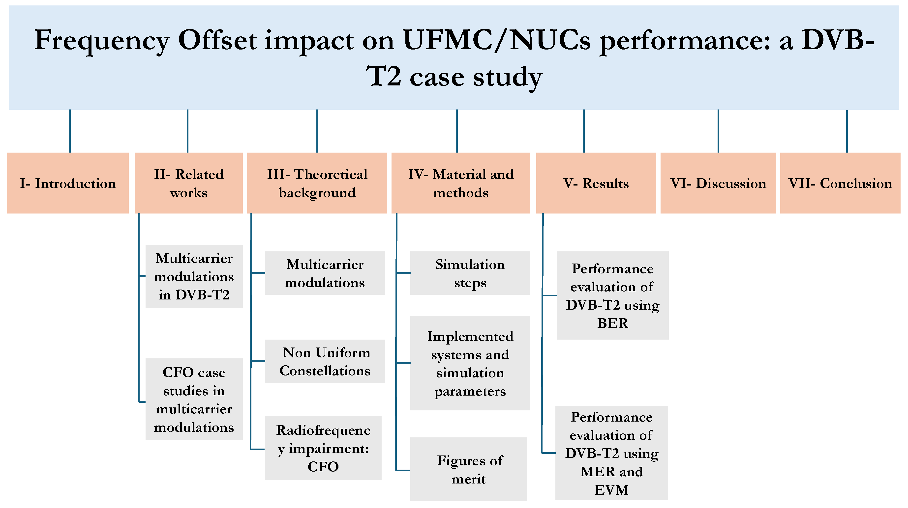
Figure 2.
CP-OFDM transceiver block diagram
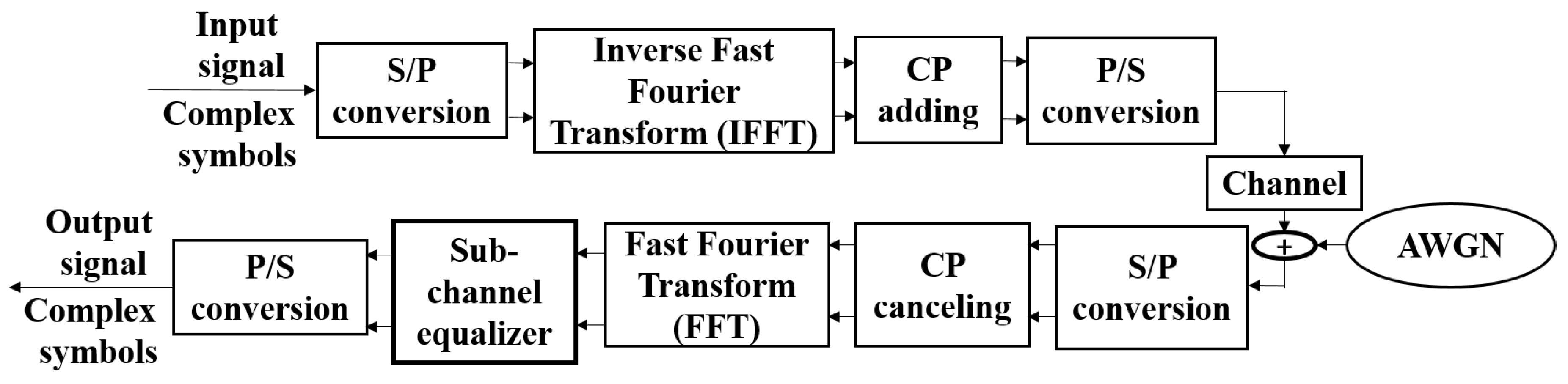
Figure 3.
CP insertion
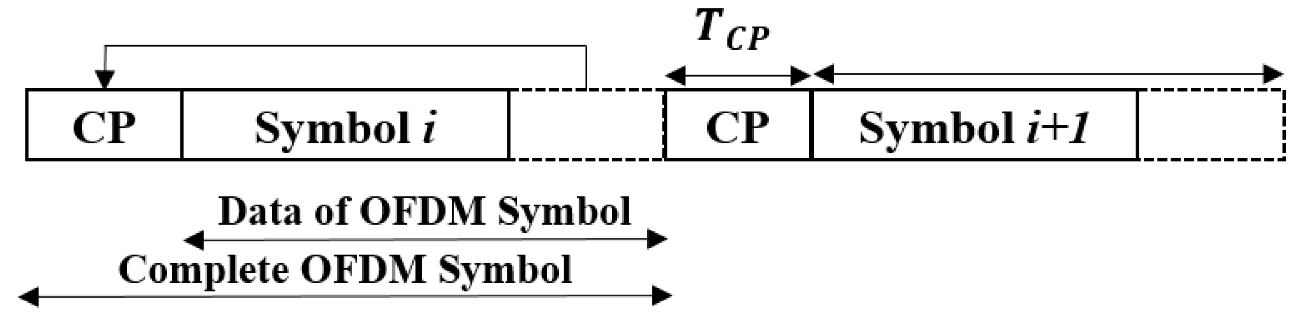
Figure 4.
UFMC block diagram
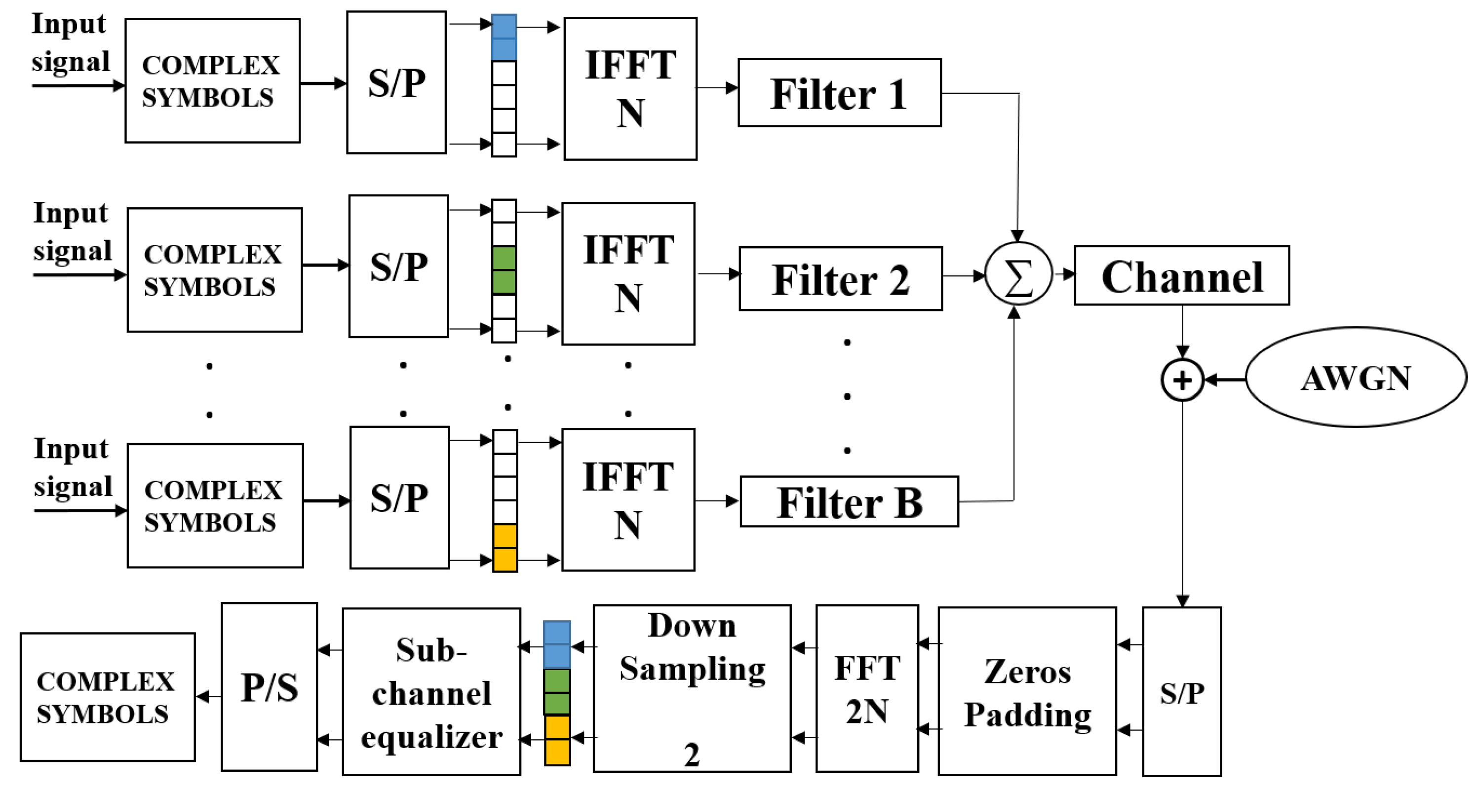
Figure 5.
OFDM modulation with frequency offset model: Gaussian Noise only
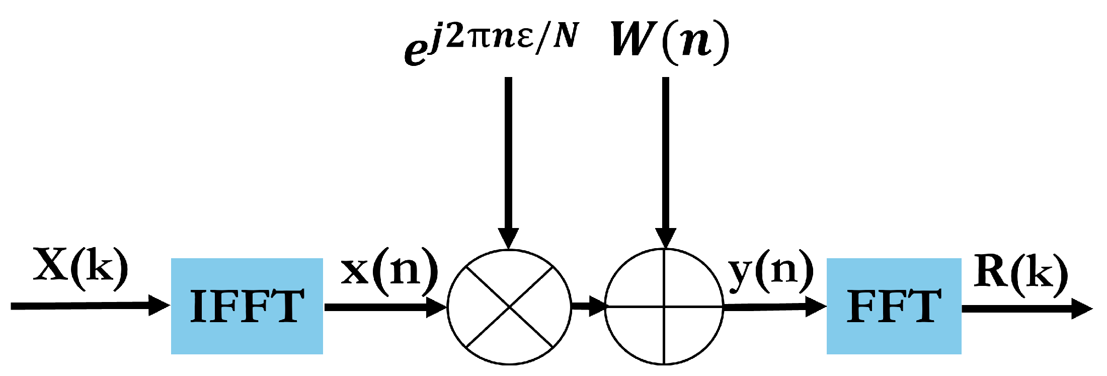
Figure 6.
OFDM modulation with frequency offset model: fading channel and Gaussian Noise only
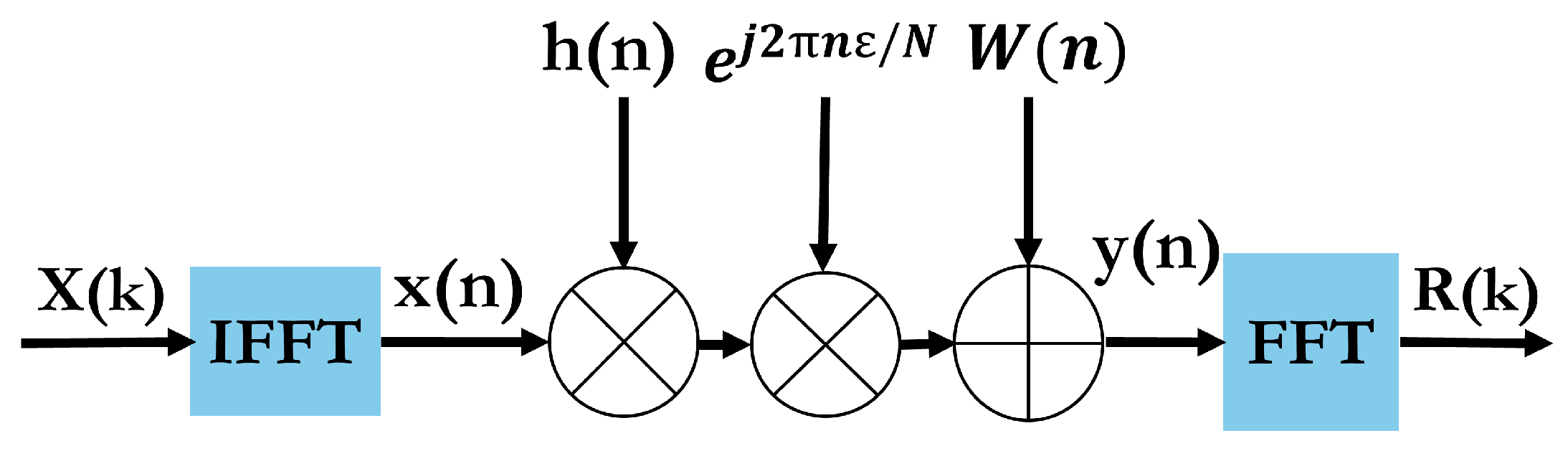
Figure 7.
CFO impact on subcarriers
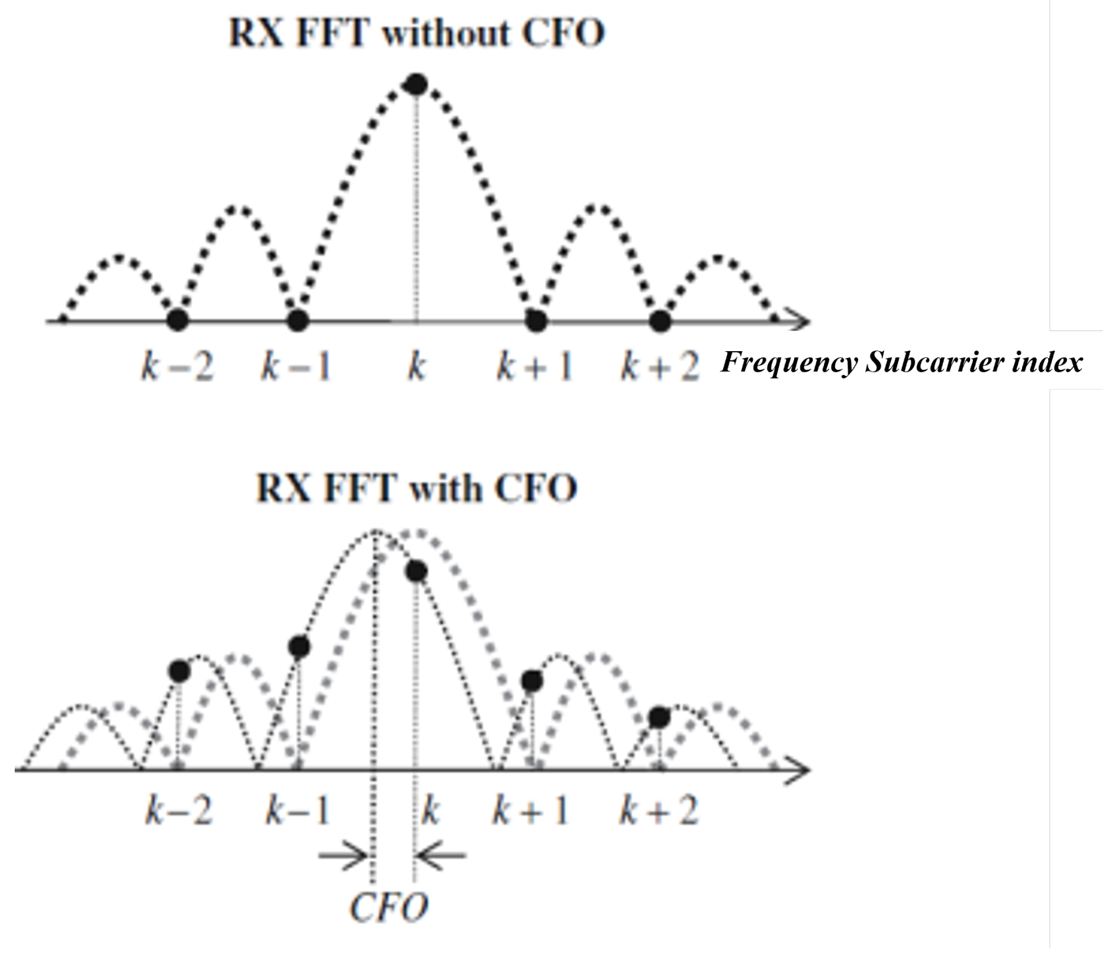
Figure 8.
Doppler effect
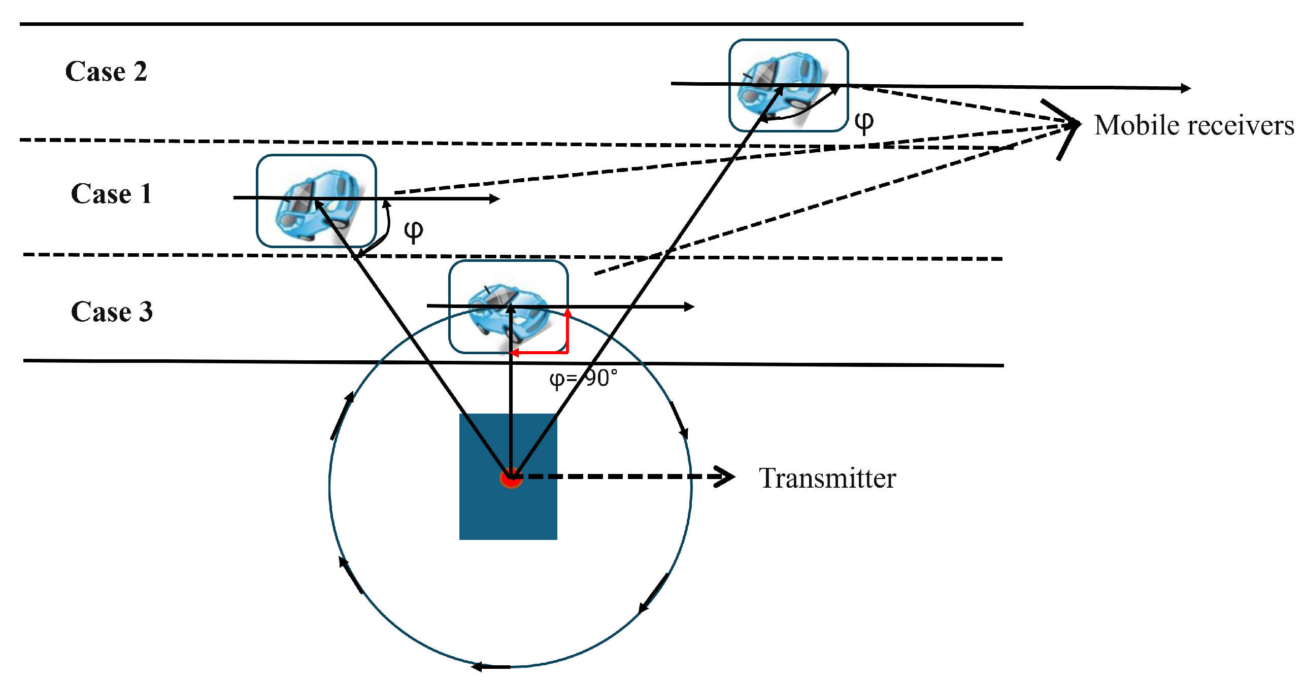
Figure 9.
CFO evaluation process in two cases: Gaussian Noise only and Gaussian Noise with TU6 fading channel
Figure 9.
CFO evaluation process in two cases: Gaussian Noise only and Gaussian Noise with TU6 fading channel

Figure 10.
Lite version of DVB-T2 system: QAM substitution by NUCs and OFDM substitution by UFMC; CFO insertion
Figure 10.
Lite version of DVB-T2 system: QAM substitution by NUCs and OFDM substitution by UFMC; CFO insertion
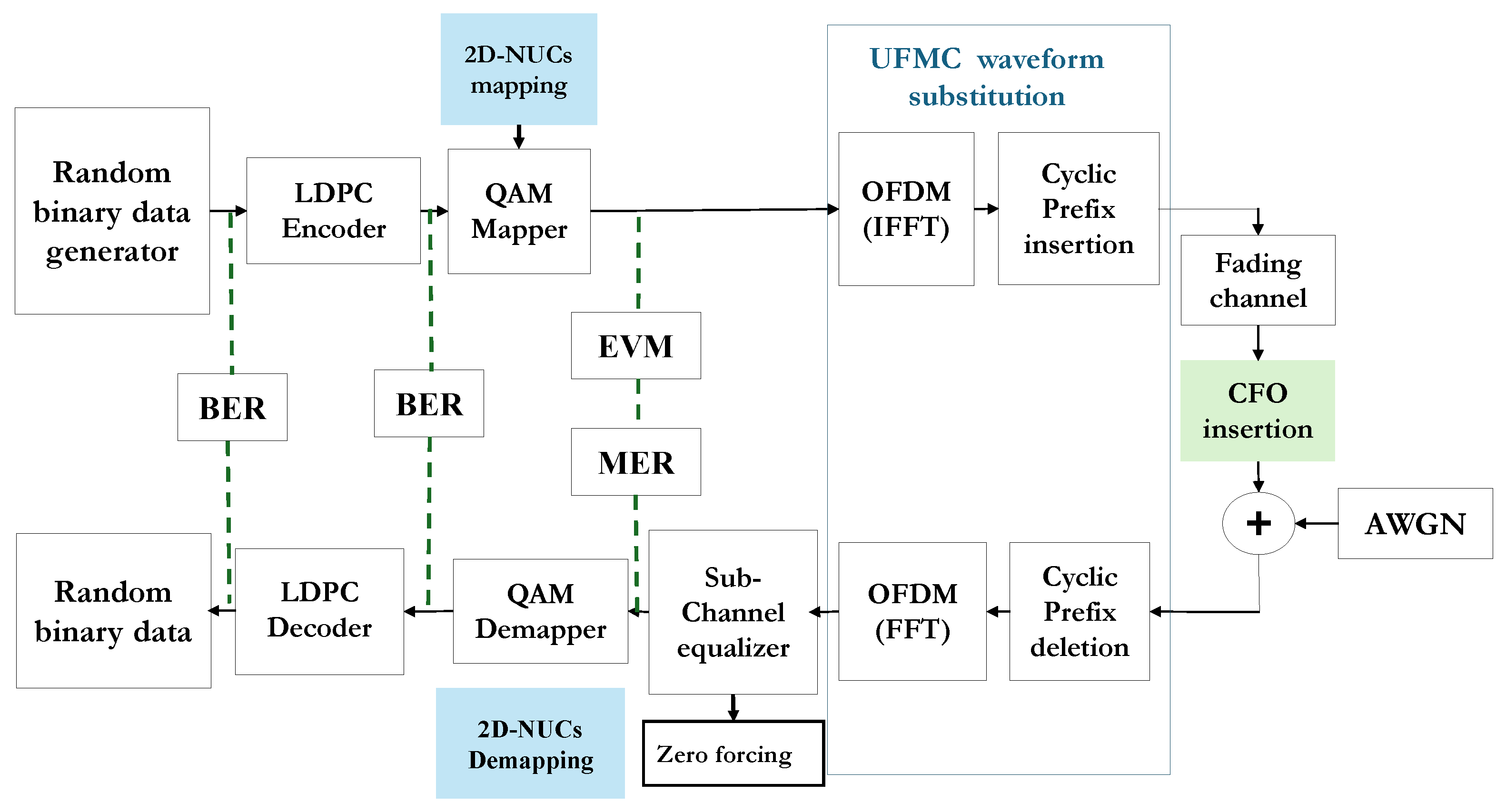
Figure 11.
UFMC/NUCs based DVB-T2 system: CFO insertion
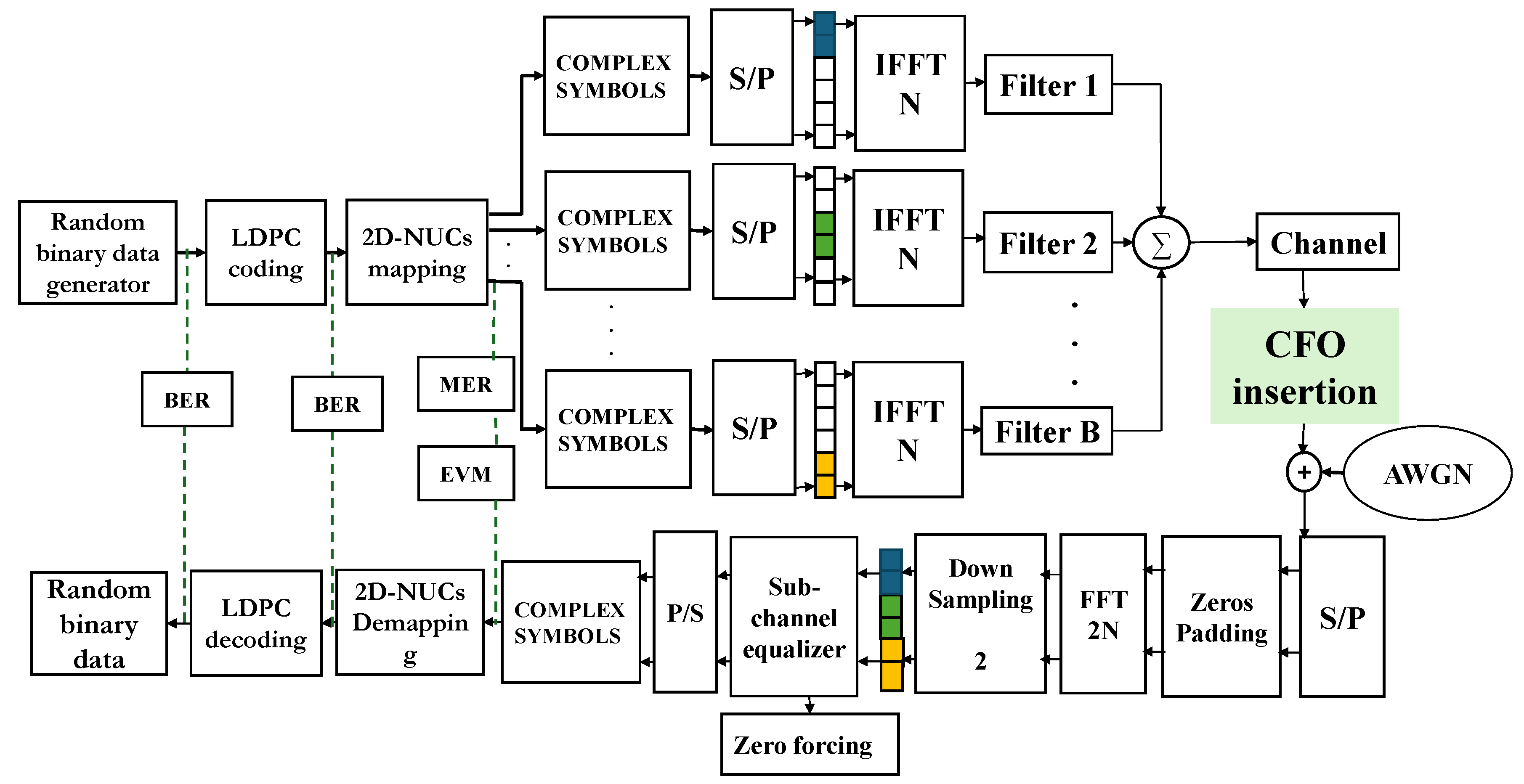
Figure 12.
BER versus SNR in the native DVB-T2 system without coding: CFO impact evaluation in AWGN case only
Figure 12.
BER versus SNR in the native DVB-T2 system without coding: CFO impact evaluation in AWGN case only
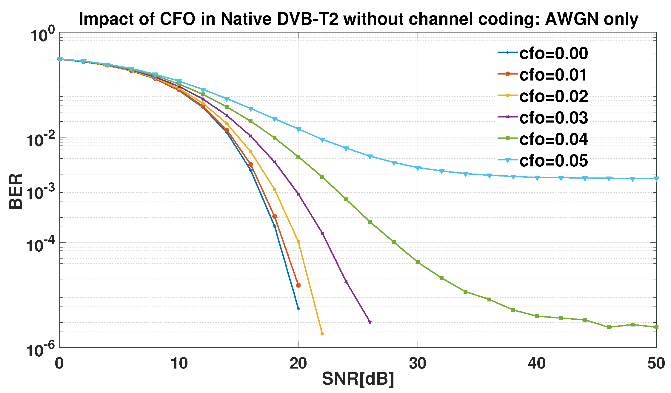
Figure 13.
BER versus SNR in the native DVB-T2 system without coding: CFO evaluation in TU6 and AWGN case
Figure 13.
BER versus SNR in the native DVB-T2 system without coding: CFO evaluation in TU6 and AWGN case
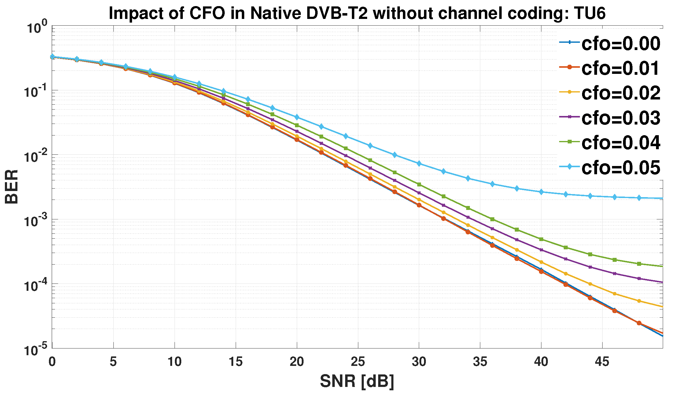
Figure 14.
BER versus SNR in the UFMC based DVB-T2 system without coding: CFO evaluation in AWGN case only
Figure 14.
BER versus SNR in the UFMC based DVB-T2 system without coding: CFO evaluation in AWGN case only

Figure 15.
BER versus SNR in the UFMC based DVB-T2 system without coding: CFO evaluation in TU6 and AWGN case
Figure 15.
BER versus SNR in the UFMC based DVB-T2 system without coding: CFO evaluation in TU6 and AWGN case
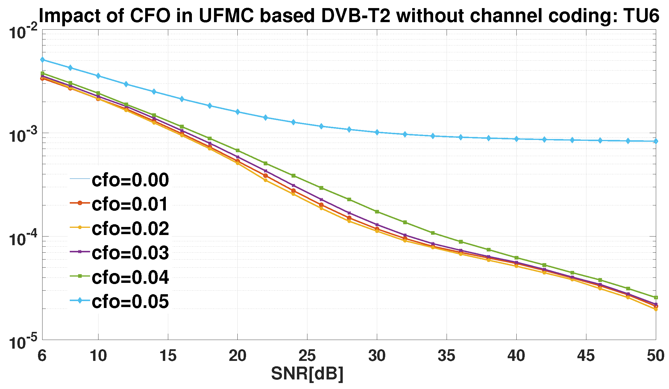
Figure 16.
BER versus SNR in the native DVB-T2 system with coding: CFO evaluation in AWGN case only
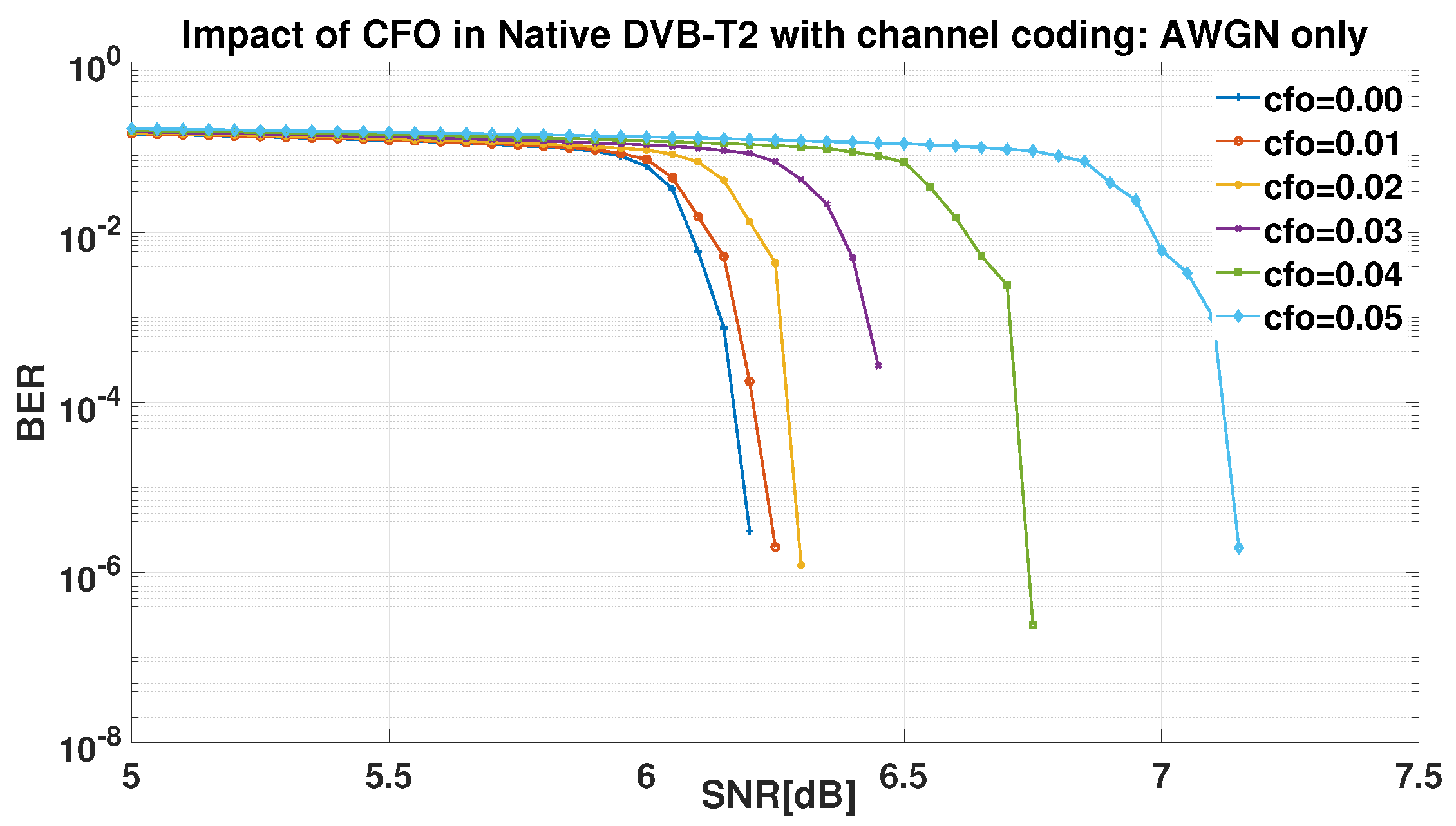
Figure 17.
BER versus SNR in the native DVB-T2 system with coding: CFO evaluation in TU6 and AWGN case
Figure 17.
BER versus SNR in the native DVB-T2 system with coding: CFO evaluation in TU6 and AWGN case
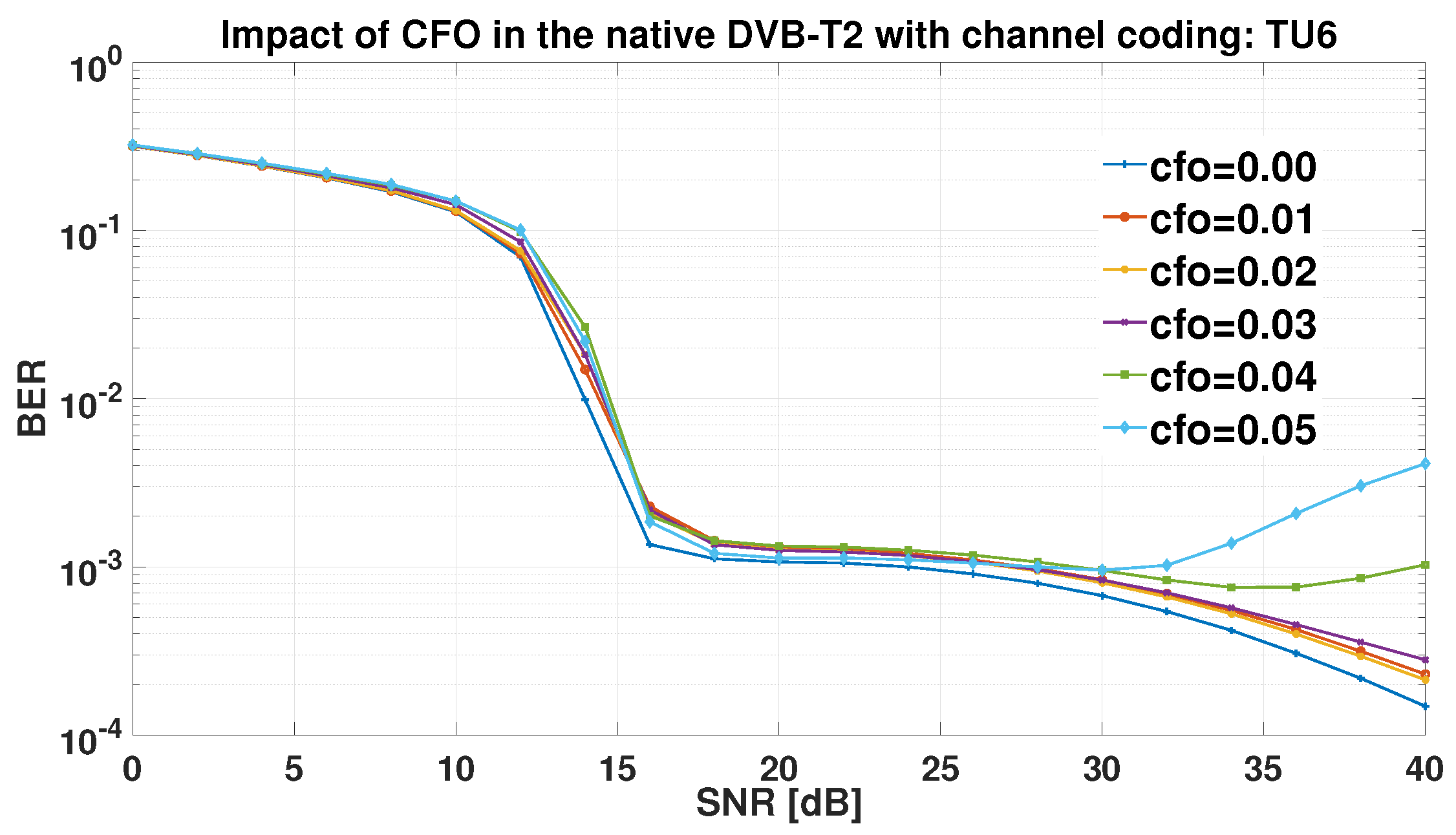
Figure 18.
BER versus SNR in the NUCs based DVB-T2 system with coding: CFO evaluation in AWGN case only
Figure 18.
BER versus SNR in the NUCs based DVB-T2 system with coding: CFO evaluation in AWGN case only
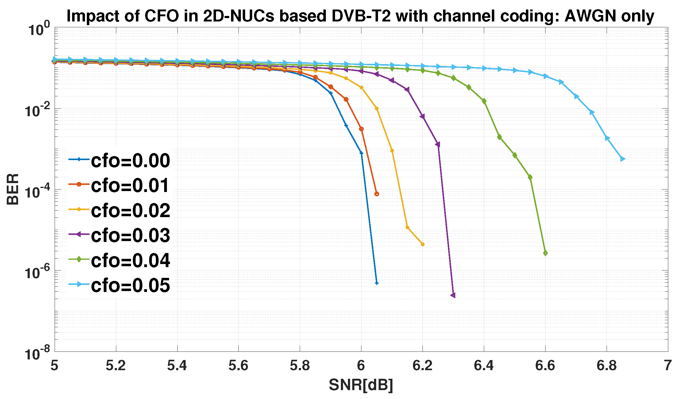
Figure 19.
BER versus SNR in the NUCs based DVB-T2 system with coding: CFO evaluation in TU6 and AWGN case only
Figure 19.
BER versus SNR in the NUCs based DVB-T2 system with coding: CFO evaluation in TU6 and AWGN case only
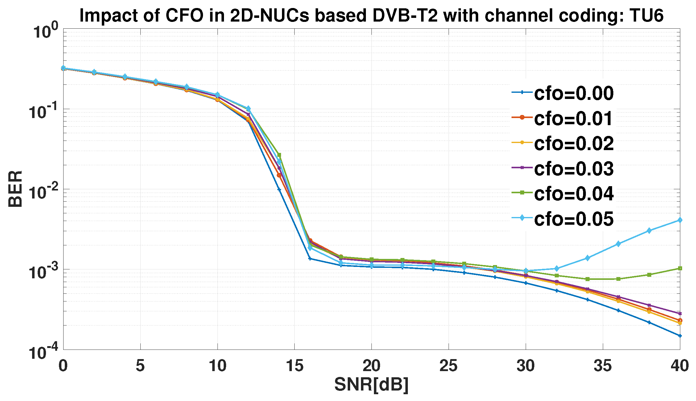
Figure 20.
BER versus SNR in the UFMC based DVB-T2 system with coding: CFO evaluation in AWGN case only
Figure 20.
BER versus SNR in the UFMC based DVB-T2 system with coding: CFO evaluation in AWGN case only
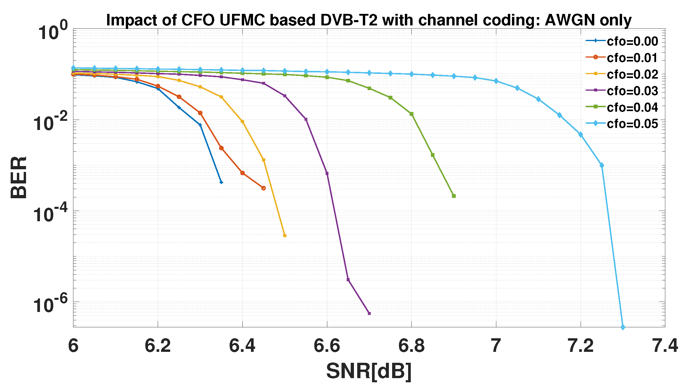
Figure 21.
BER versus SNR in the UFMC based DVB-T2 system with coding: CFO evaluation in TU6 and AWGN case
Figure 21.
BER versus SNR in the UFMC based DVB-T2 system with coding: CFO evaluation in TU6 and AWGN case
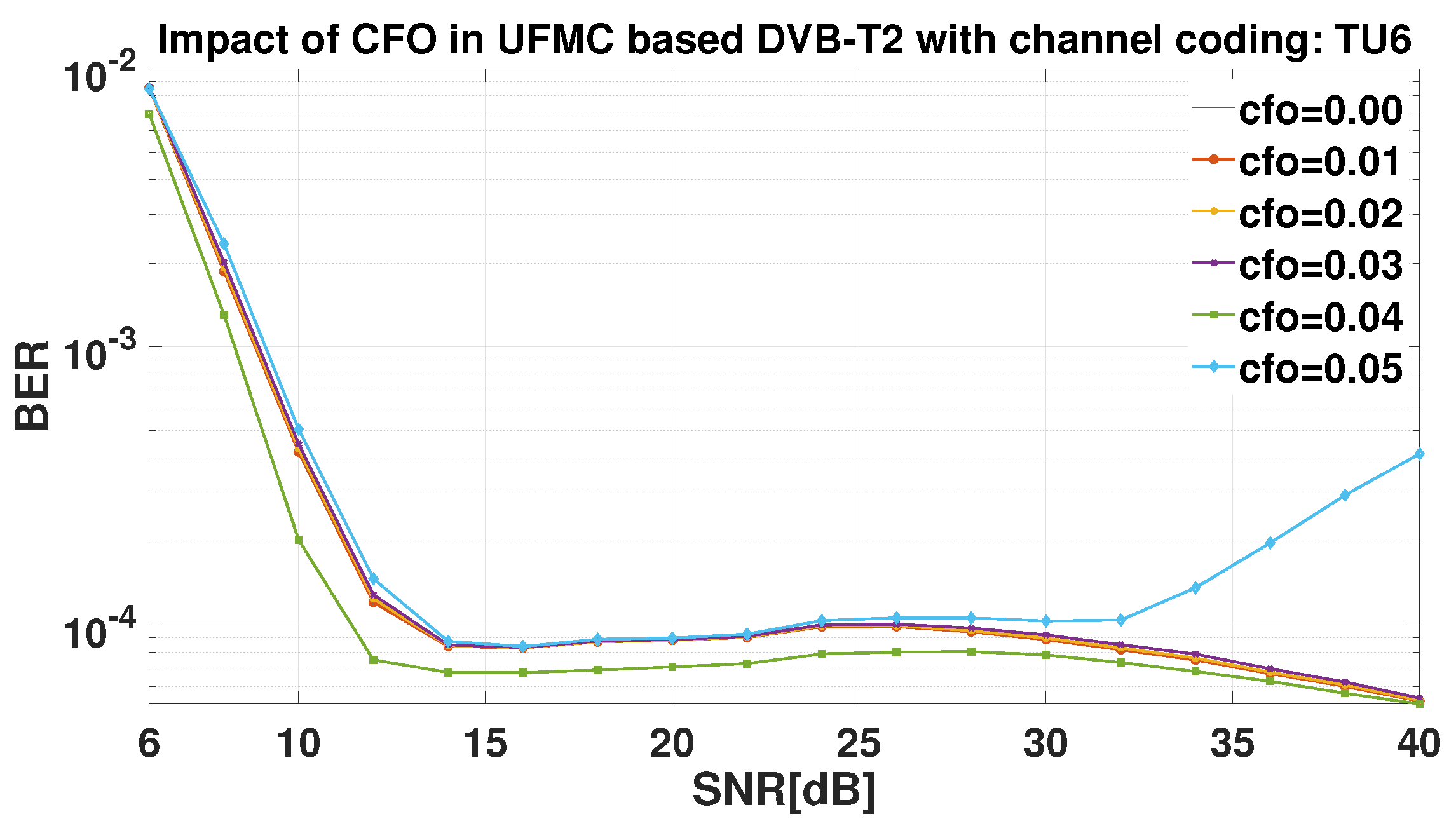
Figure 22.
BER versus SNR in the UFMC NUCs based DVB-T2 system with coding: CFO evaluation in AWGN case only
Figure 22.
BER versus SNR in the UFMC NUCs based DVB-T2 system with coding: CFO evaluation in AWGN case only
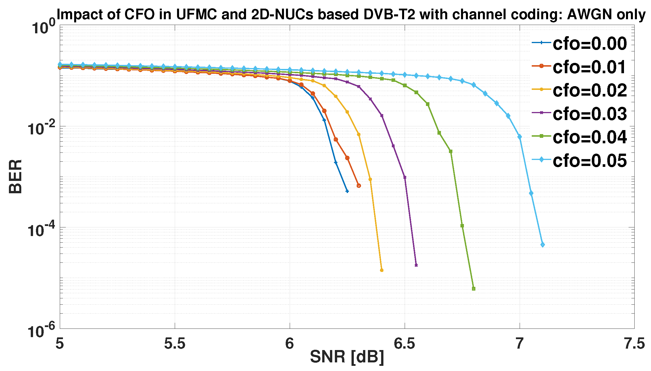
Figure 23.
BER versus SNR in the UFMC NUCs based DVB-T2 system with coding: CFO evaluation in TU6 and AWGN case
Figure 23.
BER versus SNR in the UFMC NUCs based DVB-T2 system with coding: CFO evaluation in TU6 and AWGN case
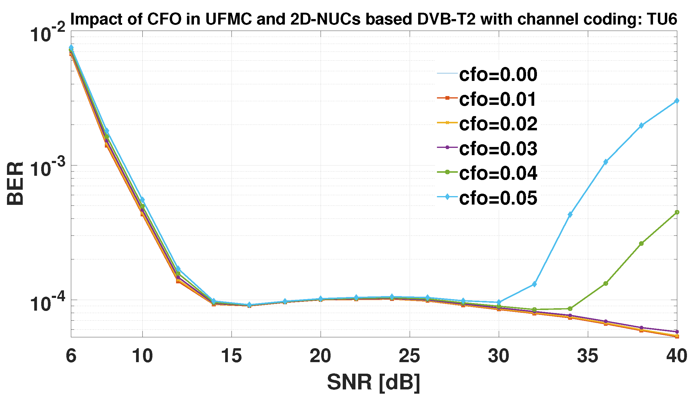
Figure 24.
MER versus SNR in the native DVB-T2 system with coding: CFO evaluation in AWGN case only
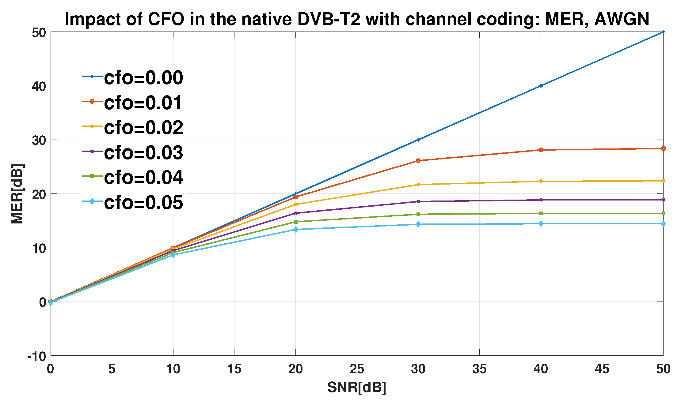
Figure 25.
MER versus SNR in the native DVB-T2 system with coding: CFO evaluation in TU6 and TU6 and AWGN case
Figure 25.
MER versus SNR in the native DVB-T2 system with coding: CFO evaluation in TU6 and TU6 and AWGN case
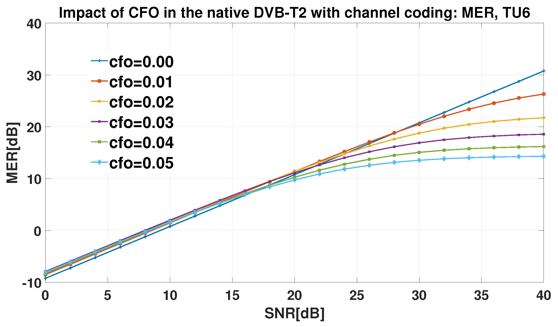
Figure 26.
EVM versus SNR in the native DVB-T2 system with coding: CFO evaluation in AWGN case only
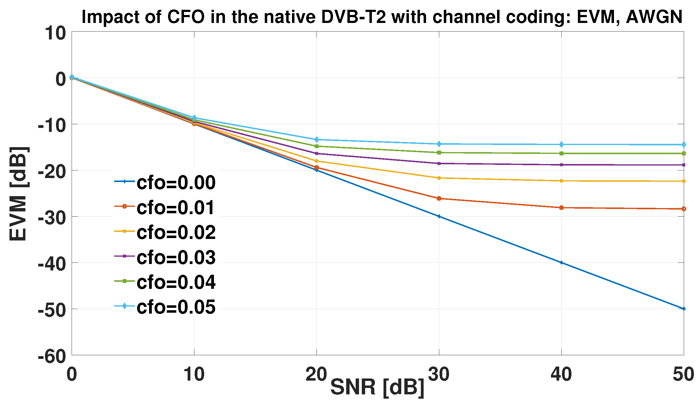
Figure 27.
EVM versus SNR in the native DVB-T2 system with coding: CFO evaluation in TU6 and TU6 and AWGN case
Figure 27.
EVM versus SNR in the native DVB-T2 system with coding: CFO evaluation in TU6 and TU6 and AWGN case
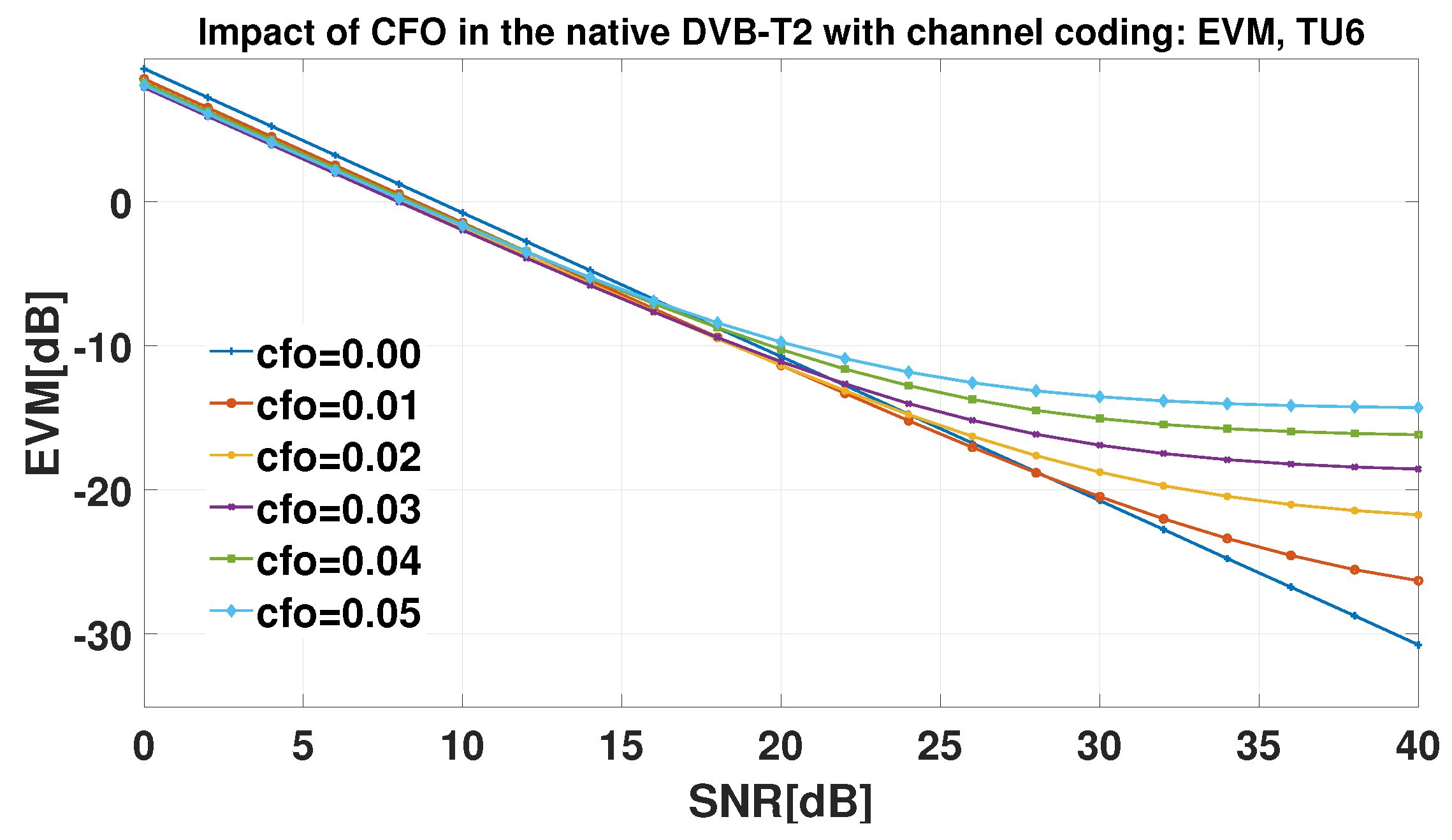

Table 1.
Literature review (with advantages and limitations) on multicarrier modulations in DVB-T2
| Papers (years) | Advantages | Limitations |
| [17] (2011) | Comparison of OFDM to FBMC using Brazil A (channel with Line Of Sight (LOS)) and Brazil D (channel without LOS) in DVB-T | Case of mobile reception not considered |
| BER versus SNR evaluated when channel coding (Reed Solomon and Convolutional code) is considered or not | MER and EVM tools are not used | |
| FBMC 1-tap and 3-tap equalizers considered | Zero-Forcing equalizer performance has not been evaluated for FBMC. Channel estimation method is not used | |
| [18] (2019) | Comparison of OFDM with FBMC using TU6 (Urban environment) and 0dB echo channel (Single Frequency Network environment) | Case of mobile reception not considered |
| BER versus SNR evaluated when channel coding LDPC is considered or not. The system performance is evaluated using Additive White Gaussian Noise (AWGN) only and using fading channels | MER and EVM tools have not been used | |
| Complex Finite Impulse Response (CFIR) 1-tap and 3-tap are considered for FBMC and zero forcing equalizer is used for OFDM | Zero-Forcing equalizer performance has not been evaluated for FBMC. Channel estimation method is not used | |
| [9] (2020) | Comparison of OFDM with UFMC and FBMC using TU6 channel in DVB-T2 | Case of mobile reception not considered |
| BER versus SNR evaluated when channel coding (LDPC) is considered or not. At a BER of , UFMC gain: , FBMC gain: 1 in comparison with OFDM | MER and EVM tools and BCH code are not used. Channel estimation methods not used | |
| Spectral efficiency of UFMC and FBM evaluated | Computational complexity not really evaluated | |
| [19] (2020) | Comparison of NUCs performance with QAM in DVB-T2 Comparison of UFMC and NUCs with OFDM and QAM using TU6 channel in DVB-T2 | Case of mobile reception not considered |
| NUCs from ATSC 3.0 standard is considered. BER versus SNR evaluated only when channel coding (LDPC) is considered. UFMC and NUCs jointly present better performance than OFDM and QAM in DVB-T2 | MER and EVM tools and BCH code are not used. NUCs constellations have not been designed for DVB-T2 but have been adapted for this system |
Table 2.
Literature review (with advantages and limitations) on multicarrier modulations in DVB-T2 (Table 1 continued)
Table 2.
Literature review (with advantages and limitations) on multicarrier modulations in DVB-T2 (Table 1 continued)
| Papers (years) | Advantages | Limitations |
| [20] (2021) | Literature review on filter based waveforms (FBMC and UFMC) implementation algorithms proposed for DTT systems | There is no development of a complexity reduction algorithm |
| Complexity computation and analysis of FBMC and UFMC compared to OFDM | The implementation of these algorithms has not been performed in DVB-T2 but this system parameters (Number of subcarriers) are used to compute complexities. | |
| Compromise between computation complexity and spectral efficiency is performed in order to choose the suitable algorithm | The simulation time of each modulation has not been evaluated in order to perform a complete analysis |
Table 3.
Literature review on CFO case study (with advantages and limitations) in multicarrier modulations
Table 3.
Literature review on CFO case study (with advantages and limitations) in multicarrier modulations
| Papers (years) | Advantages | Limitations |
| [21] (2006) | The use of one OFDM training symbol instead of two symbols to perform CFO estimation for which the half of the symbol (odd subcarrier) includes null-subcarriers | The estimation range is limited within two subcarriers spacing and should be extended |
| The use of some additional even null subcarriers reduces the computation complexity of the Fourier transform processing | This even null subcarrier allocation is critical to the system performance. | |
| [7] (2012) | The use of the tripartite structure of P1 symbols to derivate an optimum ML synchronization for P1 symbol | The P1 symbols are not known a-priori by DVB-T2 receiver. Therefore, in presence of deep fading, the estimator should be limited |
| Two estimators such as ML and Pseudo ML are proposed. Their performance and their implementation complexity are compared | DVB-T2 system performance has not been evaluated using these estimators | |
| Rayleigh channel and SFN are fading channel environments considered. The Cramér-Rao bound is estimated for both estimators | TU6 channel and various Single Frequency Network (SFN) schemes have not been considered. It has not been performed for SFN case as the CFO estimators are not suitable for SFN environment | |
| [3] (2012) | An iterative detection dual CFO compensation technique is proposed to deal with the dual phase errors experienced in DVB-T2 MISO SFN environment | Complexity of this technique has not been evaluated |
| A successive-iterative ICI cancellation technique is also proposed to deal with the additional ICI introduced by MISO technique in SFN environment | Complexity of this technique has not been evaluated | |
| The performance of both techniques are evaluated in DVB-T2 system using BER versus SNR when only the iterative detection dual CFO compensation is used and when they are both used. | Other performance evaluation tools like MER and EVM are not considered. The PDP of the MISO channel has not been defined. | |
| [22] (2012) | The numerical expression of Integer Frequency Offset (IFO) and Fractional Frequency Offset (FFO) are well developed. | Complexities of these technique are not evaluated |
| CFO estimation techniques such as frequency and time domain techniques are presented in detail. The performances of CFO estimation techniques Classen and Moose have been evaluated in OFDM transmission using BER versus SNR. | A trade-off between the performances of these techniques and their complexities has not been done to choose the better technique |
Table 4.
Literature review on CFO case study (with advantages and limitations) in multicarrier modulations (Table 3 continued)
Table 4.
Literature review on CFO case study (with advantages and limitations) in multicarrier modulations (Table 3 continued)
| Papers and years | Advantages | Limitations |
| [23] (2015) | The spectral efficiency of OFDM systems has been evaluated in the presence of Residual CFO included in the signal after applying a CFO estimation technique | The numerical expression of Signal to interference noise ratio (SINR) has been developed but the relationship between SINR and spectral efficiency has not been established. |
| The spectral efficiency of Cyclic prefix based and training based CFO estimators are evaluated and compared to the theory (Shannon capacity). MISO transmission case is also considered. | PDP of the fading channel used for imperfect CSI case has not been highlighted. | |
| [24] (2015) | The Stochastic and Determistic Maximum Likelihood (SML and DML) CFO estimation methods has been derived using the special structure of P1 symbol in DVB-T2 system | The performance of these algorithms have not been evaluated in DVB-T2 system by using BER versus SNR. Only Cramér-Rao lower bounds and Mean Square Error are used for the algorithms performance |
| These algorithms are derived with the assumption that the CSI is unknown | There is no information about the channel PDP used for simulation | |
| Performances of these techniques are evaluated and compared to the previous estimation methods proposed in literature. These algorithms can estimate both the receive signal power, the time delays and CFO | Complexities of these algorithms are evaluated by just evaluating the elapsed time of the proposed algorithms and comparing them to previous CFO estimation methods proposed. | |
| [25] (2016) | The impact of CFO on UFMC system performance has been evaluated and compared to those for OFDM. | There is a lack about the justification of CFO values used. |
| Zero forcing equalizer is used for both OFDM and UFMC. Symbol Error Rate (SER) is the tool exploited for performance evaluation | The channel PDP used has not been highlighted. | |
| [26] (2017) | The performance of single user UFMC, multi-user UFMC and MIMO-MU-UFMC systems have been evaluated and compared to those of OFDM in presence of CFO | There is a lack about the justification of CFO values used |
| Zero Forcing and MMSE equalizers are both used and their performance are compared. SER is the tool used. | The channel PDP used has not been highlighted. |
Table 5.
Simulation parameters
| Parameters | Values |
| Channel bandwidth | 8 MHz |
| 8192 | |
| OFDM Cyclic Prefix | 1/32 |
| OFDM Symbol duration | 896 s |
| OFDM Sub-carrier spacing | 1116.07 Hz |
| Constellation size | 16 |
| number of bits per symbol QAM | 4 |
| LDPC Fame length | 64800 |
| Code Rate | 1/2 |
| UFMC Filter length | /32 |
| UFMC sub-band bandwidth | 42 |
| UFMC sub-band number | 172 |
| UFMC sub-band offset | 484 |
| Normalized CFO | 0.01, 0.02, 0.03, 0.04, 0.05 |
Table 6.
Native DVB-T2 (OFDM) and UFMC based DVB-T2 performance without LDPC coding and with CFO
| AWGN case only (SNR=20dB) | AWGN and TU6 channel case (SNR=40dB) | ||||
| CFO | OFDM BER | UFMC BER | CFO | OFDM BER | UFMC BER |
| 0.00 | 0.00 | ||||
| 0.01 | 0.01 | ||||
| 0.02 | 0.02 | ||||
| 0.03 | 0.03 | ||||
| 0.04 | 0.04 | ||||
| 0.05 | 0.05 | ||||
Table 7.
Native DVB-T2 (QAM) and NUCs based DVB-T2 performance with LDPC coding and with CFO
| QAM vs NUCs: AWGN case only (||) | ||||
| CFO | Native DVB-T2 SNR [dB] | NUCs based DVB-T2 SNR [dB] | Native DVB-T2 CFO Penalties [dB] | NUCs based DVB-T2 CFO Penalties [dB] |
| 0.00 | − | − | ||
| 0.01 | 0.04|0.04|− | |||
| 0.02 | ||||
| 0.03 | ||||
| 0.04 | ||||
| 0.05 | 0.84|−|− | |||
| QAM vs NUCs: AWGN and TU6 channel case (||) | ||||
| CFO | Native DVB-T2 SNR [dB] | NUCs based DVB-T2 SNR [dB] | Native DVB-T2 CFO Penalties [dB] | NUCs based DVB-T2 CFO Penalties [dB] |
| 0.00 | - | - | ||
| 0.01 | ||||
| 0.02 | ||||
| 0.03 | ||||
| 0.04 | ||||
| 0.05 | ||||
Table 8.
Native DVB-T2 (OFDM) and UFMC based DVB-T2 performance with LDPC coding and with CFO
| OFDM vs UFMC: AWGN case only (||) | ||||
| CFO | Native DVB-T2 SNR [dB] | UFMC based DVB-T2 SNR [dB] | Native DVB-T2 CFO Penalties [dB] | UFMC based DVB-T2 CFO Penalties [dB] |
| 0.00 | − | − | ||
| 0.01 | 0.06|−|− | |||
| 0.02 | ||||
| 0.03 | ||||
| 0.04 | ||||
| 0.05 | 0.92|−|− | |||
| OFDM vs UFMC: AWGN and TU6 channel case (||) | ||||
| CFO | Native DVB-T2 SNR [dB] | UFMC based DVB-T2 SNR [dB] | Native DVB-T2 CFO Penalties [dB] | UFMC based DVB-T2 CFO Penalties [dB] |
| 0.00 | − | − | ||
| 0.01 | −|0.00|0.00 | |||
| 0.02 | ||||
| 0.03 | ||||
| 0.04 | ||||
| 0.05 | −|0.2|0.2 | |||
Table 9.
Native DVB-T2 (OFDM) and UFMC/NUCs based DVB-T2 performance with LDPC coding and with CFO
| OFDM vs UFMC/NUCs: AWGN case only (||) | ||||
| CFO | Native DVB-T2 SNR [dB] | UFMC/NUCs based DVB-T2 SNR [dB] | Native DVB-T2 CFO Penalties [dB] | UFMC/NUCs based DVB-T2 CFO Penalties [dB] |
| 0.00 | − | − | ||
| 0.01 | 0.08|−|− | |||
| 0.02 | ||||
| 0.03 | ||||
| 0.04 | ||||
| 0.05 | 0.84|−|− | |||
| OFDM vs UFMC/NUCs: AWGN and TU6 (||) | ||||
| CFO | Native DVB-T2 SNR [dB] | UFMC/NUCs based DVB-T2 SNR [dB] | Native DVB-T2 CFO Penalties [dB] | UFMC/NUCs based DVB-T2 CFO Penalties [dB] |
| 0.00 | − | − | ||
| 0.01 | −|0.00|0.00 | |||
| 0.02 | ||||
| 0.03 | ||||
| 0.04 | ||||
| 0.05 | −|0.2|0.2 | |||
Disclaimer/Publisher’s Note: The statements, opinions and data contained in all publications are solely those of the individual author(s) and contributor(s) and not of MDPI and/or the editor(s). MDPI and/or the editor(s) disclaim responsibility for any injury to people or property resulting from any ideas, methods, instructions or products referred to in the content. |
© 2024 by the authors. Licensee MDPI, Basel, Switzerland. This article is an open access article distributed under the terms and conditions of the Creative Commons Attribution (CC BY) license (http://creativecommons.org/licenses/by/4.0/).
Copyright: This open access article is published under a Creative Commons CC BY 4.0 license, which permit the free download, distribution, and reuse, provided that the author and preprint are cited in any reuse.


